Effects of van der Waals Force and Thermal Stresses on Pull-in Instability of Clamped Rectangular Microplates

1
Department of Engineering Science & Mechanics, Virginia Polytechnic Institute & State University, Blacksburg, VA 24061, USA
2
Department of Mechanical & Aerospace Engineering, Polytechnic University, Brooklyn, NY 11201, USA
3
The Bradley Department of Electrical & Computer Engineering, Virginia Polytechnic Institute & State University, Blacksburg, VA 24061, USA
*
Author to whom correspondence should be addressed.
Sensors 2008, 8(2), 1048-1069; https://doi.org/10.3390/s8021048
Submission received: 21 December 2007
/
Accepted: 14 February 2008
/
Published: 15 February 2008
(This article belongs to the Special Issue Modeling, Testing and Reliability Issues in MEMS Engineering)
Abstract
:We study the influence of von Kármán nonlinearity, van der Waals force, and thermal stresses on pull-in instability and small vibrations of electrostatically actuated microplates. We use the Galerkin method to develop a tractable reduced-order model for electrostatically actuated clamped rectangular microplates in the presence of van der Waals forces and thermal stresses. More specifically, we reduce the governing two-dimensional nonlinear transient boundary-value problem to a single nonlinear ordinary differential equation. For the static problem, the pull-in voltage and the pull-in displacement are determined by solving a pair of nonlinear algebraic equations. The fundamental vibration frequency corresponding to a deflected configuration of the microplate is determined by solving a linear algebraic equation. The proposed reduced-order model allows for accurately estimating the combined effects of van der Waals force and thermal stresses on the pull-in voltage and the pull-in deflection profile with an extremely limited computational effort.
1 Introduction
Microelectromechanical sensors are currently used in automotive electronics, medical equipment, smart portable electronics, hard disk drives, and computer peripherals [1]. Electrostatically actuated Mi-croElectroMechanical Systems (MEMS) are a special class of MEMS that use Coulomb's force as the driving mechanism in sensing and actuation. Electrostatically actuated MEMS are used as accelerome-ters [2], pressure sensors [3], and mass flow and chemical sensors [4]. Electrostatically actuated MEMS also find applications in the characterization of the material properties of thin films, such as elastic constants and residual stresses, see for example [5]. In addition to sensing applications, electrostatically actuated MEMS are employed in high-frequency signal filtering [6] and relay switches [7]. A comprehensive review of modeling of electrostatically actuated MEMS can be found in [8].
An electrostatically actuated MEMS is generally comprised of a conductive deformable electrode suspended above a rigid grounded electrode [9]. A direct current (DC) voltage applied across the two bodies results in the deflection of the deformable electrode and the consequent change in the system capacitance. When an alternating current (AC) is superimposed on the DC voltage, harmonic motions of the system are obtained that can be used to realize resonant devices. The applied DC voltage has an upper limit beyond which the electrostatic force is not balanced by the elastic restoring force in the deformable conductor. Beyond this critical voltage, the deformable conductor snaps and touches the lower rigid plate. This phenomenon is known as the pull-in instability, and it was first experimentally observed in the late sixties [10, 11]. The critical displacement and the critical voltage associated with this instability are called the pull-in displacement and the pull-in voltage, respectively. Their accurate evaluation is crucial in the design of electrostatically actuated MEMS. In micro-mirrors [12] and micro-resonators [13], the designer avoids this instability in order to achieve stable motions; while in switching applications [7], the designer exploits this effect to optimize the performance of the device.
For a wide class of electrostatic MEMS, the deformable electrode is a flat body whose thickness h is much smaller than its characteristic in-plane dimension ℓ [14]. Such electrodes can be regarded as two-dimensional (2-D) plate-like bodies. Since h/ℓ ≪ 1, an approximate distributed model can be employed, where the system kinematics is described only through the displacement of points on the movable electrode mid-surface, see for example [15]. Linear and nonlinear problems for microplates have been studied in [16–23]. When the bending stiffness of the deformable electrode is negligible as compared to its in-plane stretching and g0/ℓ ≪ 1, where g0 is the initial gap, the electrode can be regarded as a linear elastic membrane. The membrane approximation is valid for ℓ/h ≥ 400, see for example [24]. Linear micromembranes have been studied in [25–29]. As discussed in [25], the membrane approximation yields accurate results for many MEMS devices such as micro-pumps made of thin glassy polymers and grating light valves comprised of stretched thin ribbons.
With the decrease in electrostatic MEMS dimensions from the micro to the nanoscale additional nanoscale surface forces, such as the Casimir force and the van der Waals force [30–33], should be considered, see for example [34]. At small scales, the nanoscale surface forces may overcome elastic restoring actions in the device and lead to the plates' sticking during the fabrication process. van der Waals force and Casimir force can both be connected with the existence of zero-point vacuum oscillations of the electromagnetic field [31–33]. The microscopic approach to the modeling of both van der Waals and Casimir forces can be formulated in a unified way using Quantum Field Theory, see for example [30–33]. It is found that the Casimir force is generally effective at larger separation distances between the bodies than the van der Waals force. Whereas the Casimir force between semi-infinite parallel plates is inversely proportional to the fourth power of the gap, van der Waals force is inversely proportional to the third power of the gap. The dependence of these forces on the dielectric properties of the plates and the filling medium is studied in details in [31], Section 4.1.1. It is important to note that van der Waals and Casimir forces cannot in general be considered to simultaneously act in MEMS, since they describe the same physical phenomenon at two different length scales.
MEMS can be subjected to considerable temperature variations during sensing operation, such as in monitoring aircraft condition and distributed satellites communication, as well as during device packaging [35]. Modeling of the effect of temperature changes on pull-in instability of electrostatically actuated microelectromechanical switches is addressed in [36–38]. In these studies, it is observed that even a moderate temperature increase may cause premature failure of the device due to a significant decrease in the pull-in voltage. On the other hand, temperature drops may lead to considerable increase in the pull-in voltage even outside the operational range of the switch [39, 40].
We consider rectangular microplates undergoing large displacements under the combined effect of electrostatic and nanoscale forces. We use the Galerkin method to develop a tractable reduced-order model for electrostatically actuated microplates. The reduced-order model is derived by taking a family of linearly independent kinematically admissible functions as basis functions for the transverse displacement and by decomposing the in-plane displacement vector as the sum of displacements for irrotational and isochoric waves in a 2-D medium. Basis functions for the transverse and the in-plane displacements are related through the nonlinear equation governing the plate in-plane motion. The governing equations of the reduced-order model are derived from the equation governing the transverse motion of the microplate. The model is specialized to the case where a single basis function for the transverse displacement is used to yield manageable solutions. In the static analysis, pull-in parameters are found by solving a system of two nonlinear algebraic equations for the transverse displacement amplitude and the load parameter. The eigenvalue problem corresponding to linear vibrations of the system about its statically deflected position is solved for the fundamental frequency. We show that the fundamental frequency goes to zero as pull-in conditions are approached. The pull-in parameters found from the eigenvalue analysis agree well with those derived from the static analysis. We investigate effects of nanoscale forces and thermal stresses on pull-in parameters and small vibrations of electrostatically actuated microplates.
The rest of the paper is organized as follows. In section 2, we present the governing nonlinear equations of motion for a von Kármán microplate under the simultaneous effects of thermal loading, electrostatic force, and nanoscale forces. We present expressions of the distributed loads due to either the Casimir or the van der Waals forces. In section 3, we introduce a reduced-order model for the considered device that is capable of accurately predicting its dynamics. The derivation of the reduced-order model follows a procedure typically used for studying deformations of thin two-dimensional structures. That is, in-plane inertial effects are neglected, and the resulting equation is solved for in-plane displacements in terms of transverse deflections which are then substituted in the equation governing the evolution of transverse deflection. Once transverse deflections have been computed, in-plane displacements can be found. In section 3, we also briefly outline the technique used to solve equations for the reduced order model. In section 4, we present our results, that include the pull-in parameters and the fundamental frequencies for rectangular microplates. We specialize our results to the case where nanoscale effects can be subsumed into the van der Waals force and we investigate the effect of the van der Waals force on the pull-in instability and the lowest frequency of the predeformed plate. Conclusions are summarized in section 5.
2 Problem statement
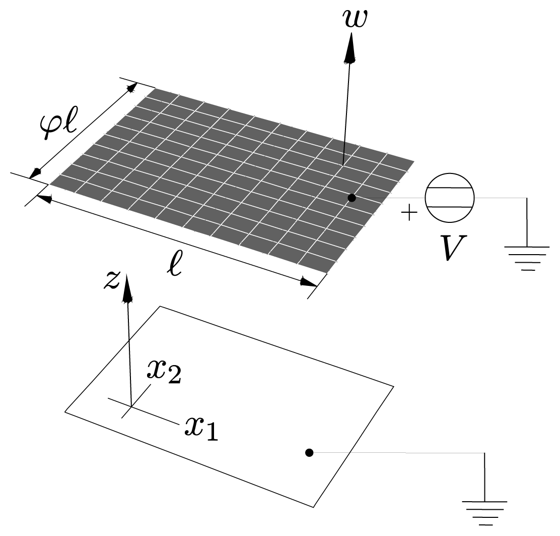
We consider a rectangular plate-like body of longer side ℓ and shorter side φℓ, φ ∈]0,1], occupying the three-dimensional region Ω × (−h/2, h/2) as depicted in Figure 1. The mid-surface Ω is described by rectangular Cartesian coordinates (x1, x2) aligned with the longer and with the shorter sides, respectively. We assume that the initial gap g0 between the two conductors and the thickness h of the deformable plate are much smaller than the characteristic length ℓ. In the proposed model, we assume that g0 and h can be of the same order of magnitude. Therefore, the maximum displacement that the device can undergo is of the order of the plate thickness h, but it is much smaller than the characteristic length ℓ, since h/ℓ ≪ 1. This implies that strains in the deformable electrode are small. Under these assumptions, we use the von Kármán plate theory to account for large deflections and small strains, see for example [41]. Neglecting the effect of the rotatory inertia, the von Kármán plate equations in Cartesian coordinates are [41]
We use the Einstein summation convention, meaning that when an index variable appears twice in a single term we are summing over the range {1,2}; free index also span the range {1,2}. Furthermore, D = Eh3/(12(1 − ν2)) is the bending stiffness of the plate, E, ν, and ϱ are Young's modulus, Poisson's ratio and mass density of the plate material, that is assumed to be homogeneous and isotropic, ui and w are the in-plane and the out-of-plane displacements of a point on the mid-surface, Fe is the Coulomb force, and Fs is the nanoscale surface force. From equation (la), we note that Coulomb and nanoscale forces act along the normal to the microplate mid-surface. This is due to the assumption of perfectly conducting material. Expressions for the Coulomb and the nanoscale surface forces are discussed below. We note that in the linear theory of a plate the transverse displacement and in-plane displacements are decoupled. Therefore, in the linear theory, the Coulomb force and nanoscale forces do not induce in-plane deformations of the microplate.
In the von Kármán plate theory, the components εij of the in-plane strain tensor are given by
We assume that the strain tensor admits the additive decomposition
, where
is the elastic strain and
the thermal one. We set
, where Θ is the uniform temperature rise, χ is the coefficient of thermal expansion assumed to be constant, and
is the Kronecker delta. Assuming the response of the material to be linear elastic, the constitutive relation under the Kirchhoff assumption is, see for example [42],
Substituting for σij from Equation (4) into equations (1) and using Equation (2), we obtain the following partial differential equations for the displacement fields ut and w
where B = Eh/(1 − v2).
From an electrical point of view, the system depicted in Figure 1 behaves as a variable gap capacitor. By assuming that g0/ℓ ≪ 1 and by neglecting fringing fields, the magnitude Fe of the Coulomb or the magnitude of the electrostatic force acting on the deformable electrode along its normal is given by the parallel plate approximation [9]
where ŵ = w/g0 is the non-dimensional transverse displacement, ϵ0 is the dielectric constant in vacuum, and V is the applied direct current voltage. Therefore, within the parallel plate approximation the expression for the electrostatic force depends only on the gap g. In [43], perturbation theory is used to develop expressions for the electrostatic force with corrections to the parallel plate approximations. It is shown that the parallel plate approximation is adequate when g0 ≪ ℓ, since the first correction multiplies the ratio
. Consistent with the parallel plate approximation for the electrostatic force, and the small deformations assumption in the mechanical model, the distributed load due to the Casimir force per unit surface area is given by the proximity force approximation [44, 45], which for perfect conductors yields:
where ћ is the Plank's constant and c is the speed of light in vacuum. Corrections to Equation (7) for geometries with known and fixed departures from the parallel configurations are reported in [44, 45]. For gaps smaller than the retardation length, that is, for gaps smaller than the wavelength of the virtual transitions responsible for the quantum dipole fluctuations [31, 33], the Casimir force reduces to the van der Waals distributed force per unit surface area [46–48]
In Equation (8), A is the Hamaker constant, see for example [31], with values in the range [0.4,4] × 10−19J. *
van der Waals and Casimir forces between parallel layered metallic surfaces have been extensively studied in the literature, see for example [31, 33]. For gold-coated aluminum surfaces, it is found that van der Waals force, see Equation (8), is effective in the gap range 0.5 nm – 4 nm. For gaps in the range 4 nm − 1 μm, there is a transition between the force-distance dependence g−3 (van der Waals force) to the force distance dependence g−4 (Casimir force). For gaps larger than 1 μm, the interaction between the plates is described by the Casimir force, see Equation (7). Therefore, for perfect conductors, at large separation distances the interaction force is independent of the material properties of plates, whereas, as the gap decreases, the interaction force is affected by the material properties of the system. For dielectric bodies, the van der Waals force is effective at larger distances as shown in [49].
The effect of the Casimir force on pull-in parameters of von Kármán microplates has been studied in [20, 21]. In the present work, we focus only on the van der Waals force. Therefore, we set Fs = FvdW in equation (5a).
We introduce the non-dimensional time t̂ = t/τ, where
and the non-dimensional in-plane displacement
. Coordinates x1 and x2 are nondimension-alized as x̂1 = x1/ℓ, x̂2 = x2/ℓ. Henceforth, we use a superimposed dot to denote time derivative with respect to t̂. Also, we drop the superimposed hat on non-dimensional variables. Thus, equations (5) become
where
The non-dimensional parameters β, λ, and μ are indicators of the effects of thermal stress, the Coulomb force, and the van der Waals force, respectively, on the MEMS dynamics. We quantify the order of magnitude of different terms in equations (10) through the order of magnitude of the corresponding non-dimensional parameters. Since the von Kármán approximation holds for h/ℓ ≪ 1, we neglect the inertial term in equation (10b) to obtain
We note that Equation (12) implies a time-independent link between the in-plane and the transverse displacements.
We consider the boundary Γ of Ω to be clamped. The kinematic boundary conditions for a clamped edge are [50]
Initial conditions are not needed since we either study static deformations of the MEMS, or analyze frequencies of small vibrations around an electrostatically deformed configuration.
3 Reduced-order model
A closed-form solution of the initial-boundary-value problem defined in equation set (10) and boundary conditions in equation set (13) cannot be found. We construct an approximate solution by expressing the displacement fields ui, with i = 1, 2, and w as
where w̄(n) and ū(p)i are basis functions for the transverse and the in-plane displacements and ζ(n) and ξ(p) are the corresponding amplitude parameters or equivalently the mode participation factors. Basis functions are collected into the N- column vector W and into the P- column vector Ui, respectively, and amplitudes are collected into the N- column vector ζ and into the P- column vector ξ, respectively. Each basis function satisfies the corresponding kinematic boundary conditions prescribed through equation set (13).
In [20], it is shown that accurate solutions for pull-in parameters of von Kármán microplates can be obtained by using a properly selected single basis function for the transverse displacement in equation (14a), that is, by setting N = 1 in equation (14a). Therefore, we derive the reduced-order model by approximating the transverse displacement field as
3.1 Basis functions for in-plane displacement
Basis functions for the in-plane displacement can be determined by solving the following linear eigenvalue problem associated with equation (10b), see for example [41],
where κ is the wave number. Following [41], we decompose the in-plane displacement as
, with i = l, 2, where
and
are displacements associated, respectively, with the longitudinal and the transverse waves, and satisfy
Therefore, Equation (16) is equivalent to the following pair of partial differential equations [41]
where
and
are wave numbers of the longitudinal and the transverse waves, respectively.
By integrating over the domain Ω and by applying Green's formulas to transform surface integrals into line integrals, equation set (17) implies the following set of boundary conditions for the displacements associated with the longitudinal and the transverse waves
Therefore, basis functions for the in-plane displacement are given by
where Amn are constants used for normalization, and p = (m − 1)q̄ + n for m = 1, …, p̄ and n = 1, …, q̄.
3.2 Relation between ξ, and ζ
In order to express the coefficients ξ, in terms of the single coefficient ζ, we substitute expressions for the displacement fields given in equations (14b) and (15) into Equation (12), premultiply both sides of the resulting equation with the transpose of the in-plane basis functions vector U, and integrate over the domain Ω. By applying the divergence theorem and by imposing the boundary conditions in equation (13b) on the boundary integrals, we finally obtain
where the scalar quantity Ξ(p) is defined through
Equation (22) implies that the full set of amplitude parameters describing the in-plane motion can be obtained from the single transverse amplitude parameter ζ through the scalar parameter Ξ(p) defined in Equation (23). In addition, we note that the relation between the in-plane motion and the transverse motion is nonlinear and that the in-plane motion vanishes in the linear theory. Because of the P internal constraints (22), the reduced-order model for the microplate has 1 degree of freedom.
3.3 Governing equations of the reduced-order model
The reduced-order model is obtained by premultiplying both sides of equation (10a) with w̄, integrating the resulting equation over Ω, and substituting into the resulting equation the approximations given by equations (14b), (15), and (22). We thus obtain
Where
From equations (23) and (25), we note that the normalization constants Amn introduced in Equation (21) do not affect ε̄ij. By using the divergence theorem and by imposing the boundary conditions in equation (13a), we obtain the following equation for the reduced-order system
where
Equation (26) describes a nonlinear mass-spring single degree-of-freedom system, where the spring force is the combination of a number of concurring phenomena: linear bending (k1ζ), thermal stress (k2ζ), nonlinear membrane stretching (k3ζ3), the Coulomb force (λfe(ζ)), and the van der Waals force (μfvdW(ζ)). From Equation (26), we note that an increase in the device temperature, that is, decreasing the parameter β, results in mechanical softening effect, whereas a decrease in the device temperature yields a mechanical stiffening effect. As the parameter β decreases mechanical buckling due to thermal stress can be reached.
In what follows, we discuss two equivalent methods to extract static pull-in parameters. The first method is based on the solution of the static problem, while the second one is based on the study of small vibrations of the system around its static equilibrium configurations. The method based on the vibration analysis can be used to experimentally determine the pull-in voltage without potentially damaging the MEMS [51].
3.4 Extraction of pull-in parameters from the static problem
At the onset of instability the system's tangent stiffness
vanishes. The quantities in Equation (28) are defined by
Therefore, at the pull-in instability, the reduced-order model satisfies Equation (26) with ζ̈ = 0 and the additional condition
We solve the problem for λ = 0 to compute the critical value, say μcr, of the van der Waals force parameter. When μ = μcr the system collapses spontaneously without applying any voltage, that is, for V = 0. We note that the critical value of the van der Waals force parameter depends on the parameter β that directly affects the mechanical stiffness. By eliminating μ from equations (26) and (30) with ζ̈ = 0 and λ = 0, we obtain the nonlinear equation
whose positive first root gives ζcr. The corresponding value of μcr is given by
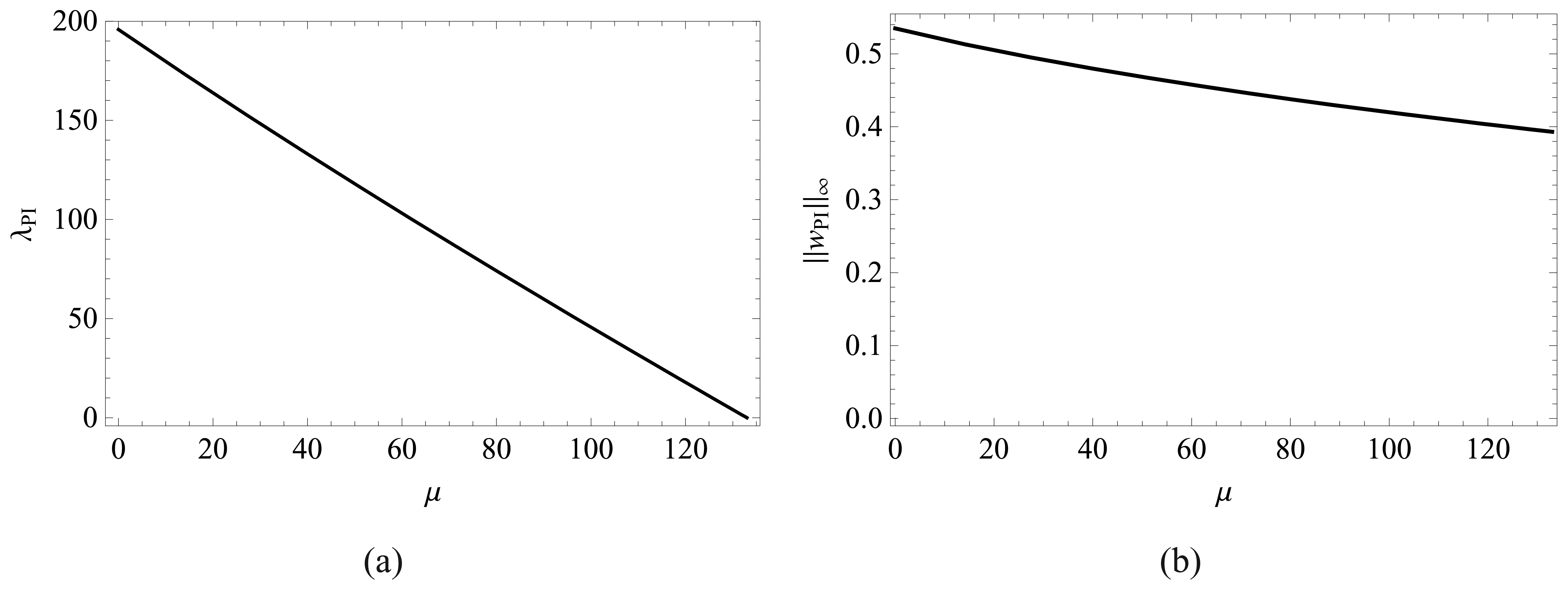
The effect of the van der Waals force on pull-in parameters λpi and ║wPI║∞ is investigated by solving equations (26) and (30) with ζ̈ = 0 and variable λ for different values of μ in the range [0, μcr]. Here, ║ · ║∞ is defined as max(x1,x2)∈Ω | · |. By solving Equation (30) for λ and by substituting in Equation (26), we obtain the following nonlinear equation in ζPI:
The lowest positive root of Equation (33) gives the non-dimensional pull-in deflection ζPI. The corresponding non-dimensional pull-in voltage is thereby determined from Equation (26) with ζ̈ = 0 as
3.5 Buckling thermal stress parameter from the static problem
The buckling thermal stress parameter βB for a given λ and a given μ is determined by eliminating β from equations (26) and (28) with ζ̈ = 0. The lowest positive root of the resulting nonlinear equation
gives the value ζ B of the displacement parameter corresponding to buckling instability. The parameter βB is obtained as
3.6 Extraction of pull-in parameters from the linear eigenvalue problem
We determine the lowest frequency of the deflected plate at a given solution (ζ, λ, μ) through the following procedure. We perturb the equilibrium state ζ with a harmonic term exp (iωt) as ζ(t) + ζ̲ exp (iωt), where ζ̲ is a constant such that |ζ̲| ≪|ζ| and
. Substituting into Equation (26) and retaining terms linear in ζ̲, we obtain the following relation for the fundamental frequency w0
Since the tangent stiffness defined in Equation (28) is zero at pull-in, it follows that at pull-in the lowest natural frequency of the system equals zero. This can be viewed as an alternative way of defining the static pull-in [18,19,51,52].
4 Results and discussion
Integrals appearing in the governing equations of the reduced-order model, including equations (23) and (27), are evaluated using the 21 x 21 Gauss quadrature rule. We established convergence of the adopted Gauss quadrature rule by checking that the values of the above integrals do not change by considering more quadrature points for numerical integration. Results presented below are for ν = 0.25.
For the transverse displacement, we use the following kinematically admissible function in Equation (15)
where ϑ0 = 4.73004 is the lowest nonzero root of the transcendental equation cosh ϑ cos ϑ = 1, and the constant A0 is chosen by normalizing w̅ with respect to its maximum value. The basis function in Equation (38) equals the product of the first transverse modes of vibration of clamped-clamped Euler beams of lengths 1 and φ, respectively.
Since w̅ in Equation (38) is symmetric about the axes x1= 1/2 and x2 = φ/2, the basis functions u(p)i in Equation (21) with mod (mod(m, 2) + mod(n, 2), 2) = 0 imply Ξ(p) = 0 in Equation (23). Here, mod(m, n) gives the remainder in the division of m by n. Therefore, the number of degrees of freedom in equation (14b) is given by
where only basis functions u(p)i such that mod (mod(m, 2) + mod(n, 2), 2) = 1 are considered. Results below are computed by selecting p̅ = q̅.
In [20], it is shown that convergent solutions for pull-in parameters of rectangular von Kármán mi-croplates are obtained for p̅ = q̅ = 4, corresponding to P = 8. Thus, results presented herein are computed with 9 basis functions in the reduced-order model.
4.1 Critical value of van der Waals force parameter
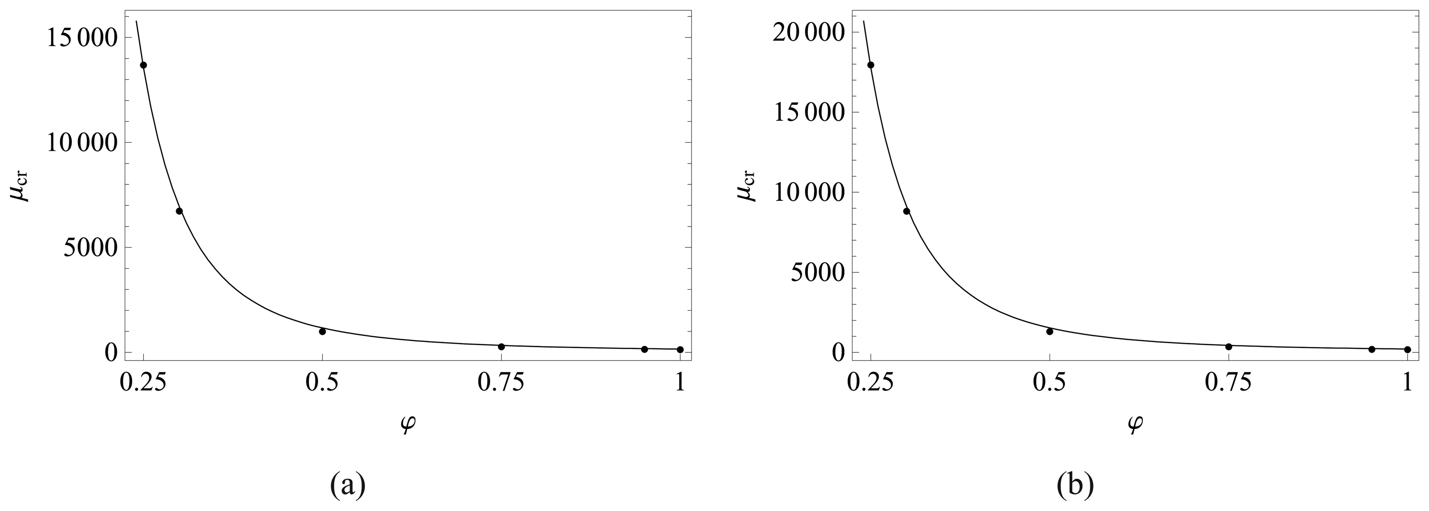
Figure 2 shows the variation of the critical van der Waals force parameter μcr with respect to the aspect ratio φ for two values of
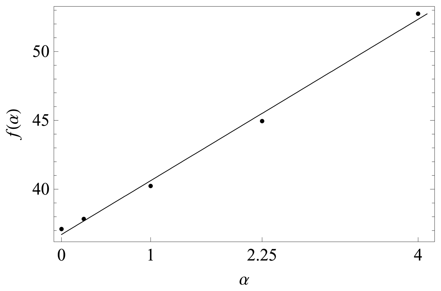
and for λ = 0 and β = 0. Numerical data in Figure 2 are interpolated with
where the function f(α), plotted in Figure 3, is given by
We note that the critical parameter μcr increases rapidly as the plate aspect ratio φ decreases. We further remark that if two opposite edges are clamped and the remaining two edges are left traction free, the MEMS can be modeled as a plate undergoing cylindrical deformations [52]. In the case of slender electrodes, effect of fringing fields that has been discarded in this work becomes relevant as discussed in [53-55]. It is highly unlikely that clamped rectangular plates with φ ≪ 1 will be used in practice due to their relatively high stiffness. For φ ≪ 1 and the longer edges traction free, the MEMS can be modeled as a beam for which the analysis in [53, 54] applies.
For the Casimir force, the function f(α) in Equation (41) equals 2.31α + 35.8; see [20]. As pointed out in [20], Equation (40) gives approximate values of μcr
4.2 Effect of van der Waals force on pull-in parameters
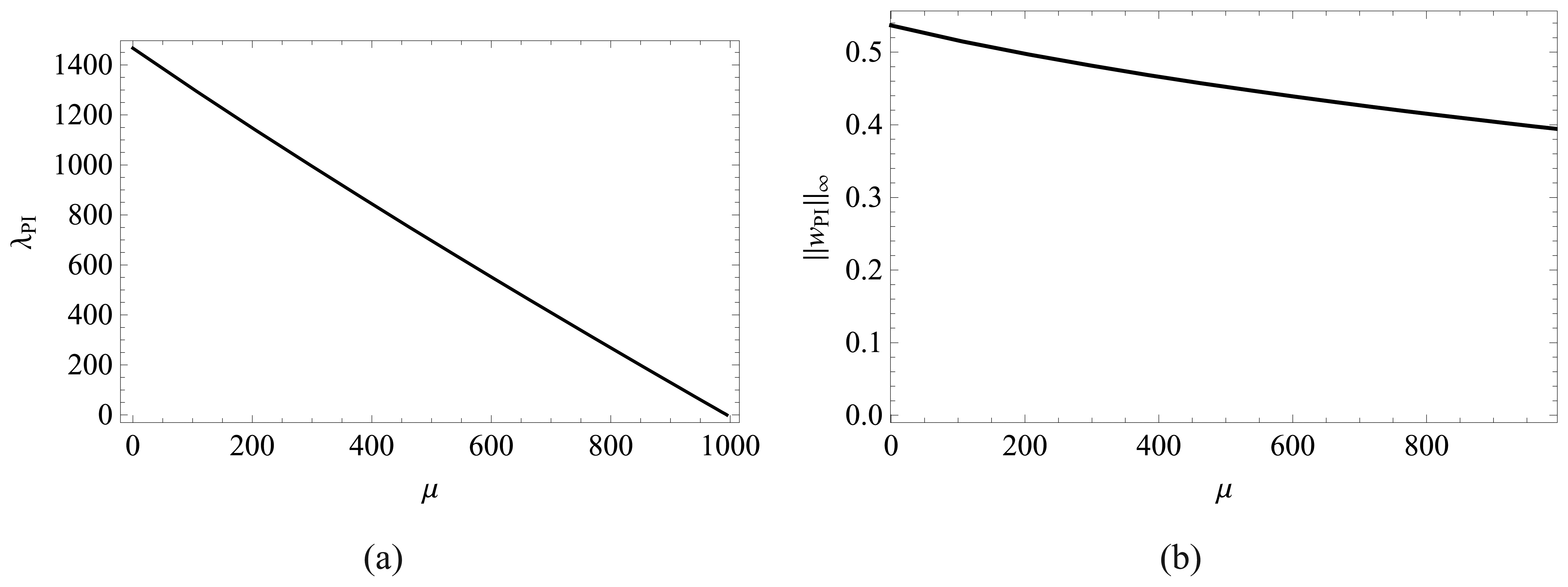
In Figures 4 and 5, we plot the pull-in parameters versus μ in the range [0, μcr] for α = 1 and β = 0 for a square and a rectangular plate. As μ increases the pull-in parameter λPI decreases monotonically from its maximum value
corresponding to μ = 0 to its minimum value 0 corresponding to μ = μcr.
The value μ = μcr. represents the intersection of the curves with the horizontal axis. With an increase in μ, the non-dimensional maximum transverse displacement decreases monotonically from its maximum value
attained for μ = 0 to its minimum value corresponding to μ = μcr. For a MEMS made of a specified material, Equation (11)5 implies that
is proportional to μcr. Thus, μcr provides a quantitative indication of the devices' size that can be safely fabricated. This means that reduced deflection ranges are allowable for devices having a large value of μcr since μcr is inversely proportional to
. By comparing results depicted in Figures 4 and 5, we conclude that a change in the aspect ratio of a plate from 1 to 1/2 significantly increases
and it does not noticeably affect the difference
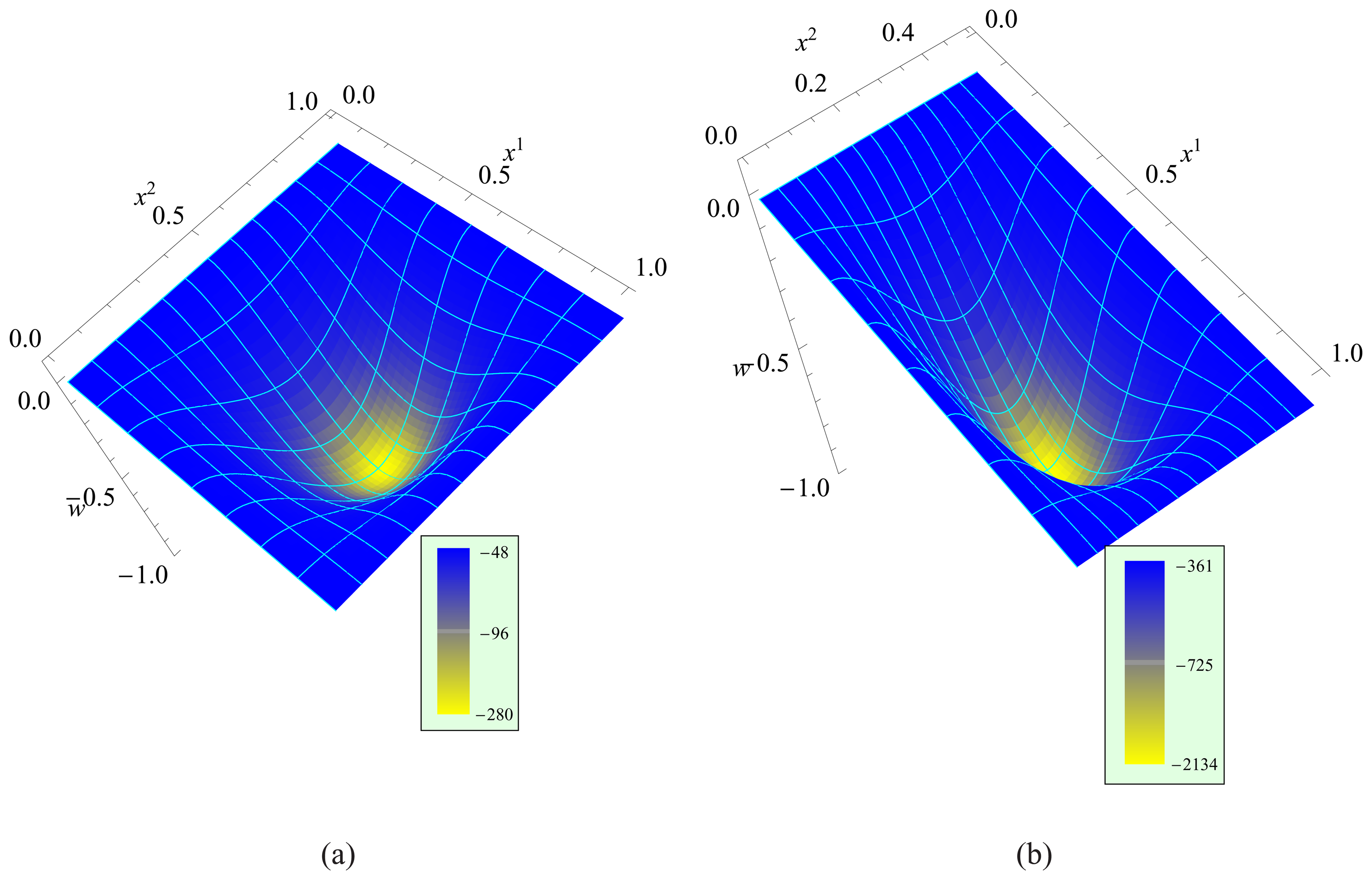
For μ = 0.3μcr and α = 4, we depict in Figure 6 deformed shapes of a square plate when λ ⋍ 200 and ‖w‖∞ ⋍ 0.59, and of a rectangular plate with φ = 1/2 when λ ⋍ 1500 and ‖w‖∞ ⋍ 0.59. In both cases thermal effects are discarded by selecting β = 0. Fringe plots of the van der Waals pressure (cf. Equation (8)) are also exhibited in the same plots. For the same value of ‖w‖∞ the maximum magnitude of the van der Waals pressure for the rectangular plate is nearly an order of magnitude higher as compared to that for the square plate; note that FvdW in Equation (8) does not depend upon the applied voltage. Its value is negative because it acts along the negative z-axis.
4.3 Effect of thermal stress on pull-in and critical van der Waals force parameters
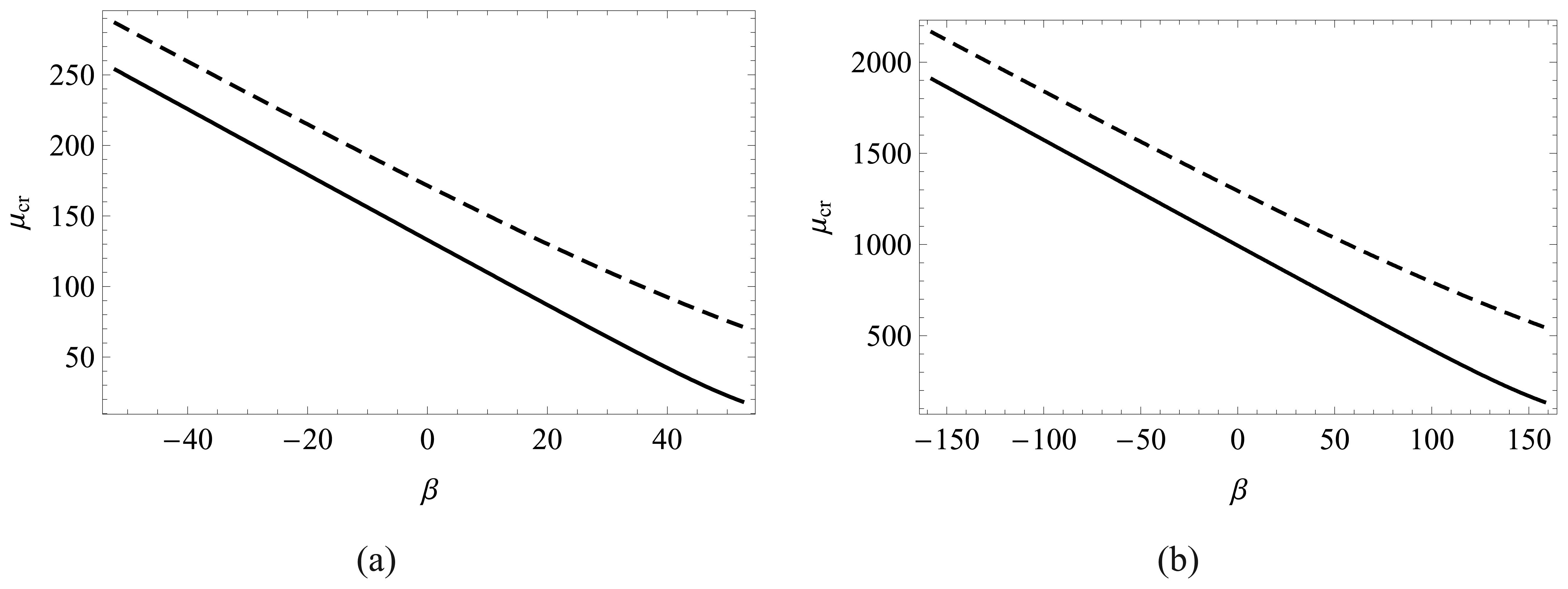
In Figure 7, we plot the variation with β of the critical van der Waals force parameter μcr for a square plate and a rectangular plate with φ = 1/2, and also two values of α. We recall that the parameter β in Equation (11) is a measure of the prestress due to a uniform change Θ in the microplate temperature. For each case examined, we observe that μcr increases with decreasing temperature and decreases with increasing temperature. Indeed, from equations (11) and (28), a positive increment of temperature decreases the overall stiffness, whereas a negative increment increases the overall stiffness. Thus, the temperature affects the minimum size of the device that can be safely fabricated.
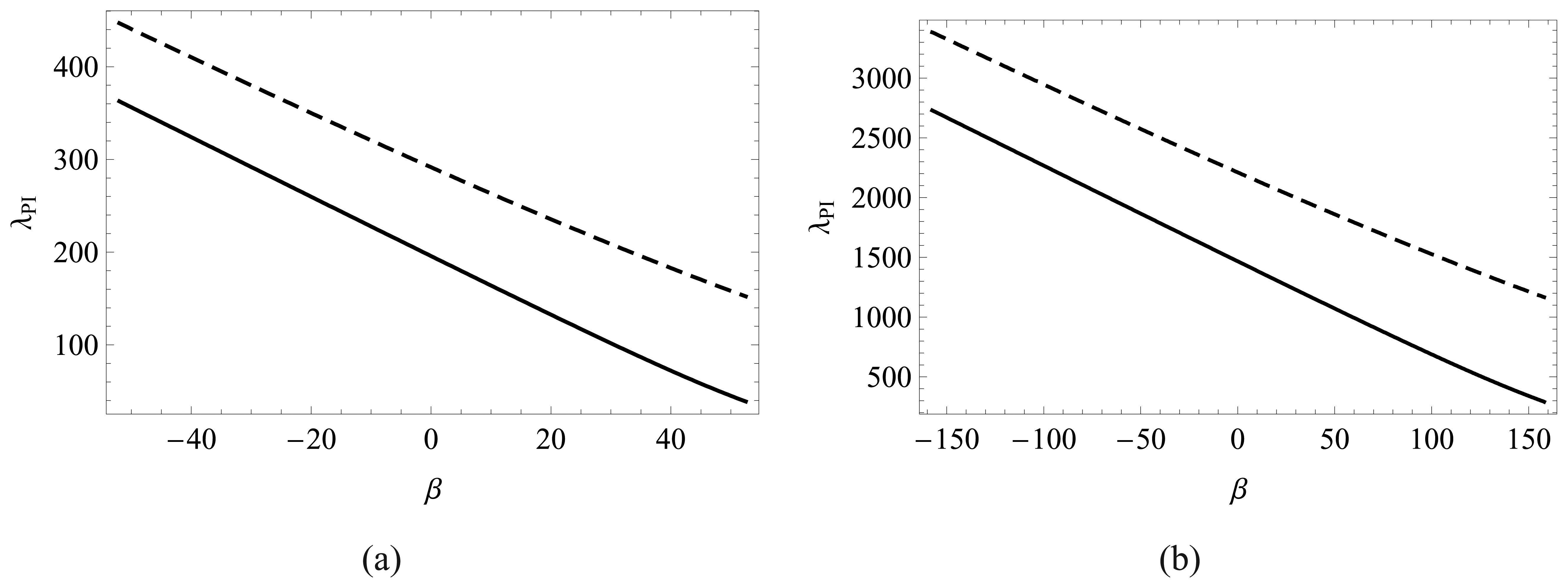
In the absence of van der Waals force, that is, for μ = 0, Figure 8 exhibits the variation with the prestress parameter β of the pull-in voltage λPI for a square plate, and a rectangular plate with p = 1/2, and also two values of α. We note that magnitudes of the compressive and tensile thermal stresses are limited, respectively, by the buckling instability of the MEMS and the tensile strength of the material of the MEMS.
4.4 Pull-in parameters from the analysis of frequencies of a deformed plate
In Figure 9, we report, for two different values of μ, the fundamental frequency w0 of the deflected microplate versus A for α = 4 and β = 0 and for a square and a rectangular plate. The natural frequency is normalized with respect to the value w̅0 corresponding to λ = 0; values of non-dimensional w̅0 for Figures 9 and 10 are reported in Table 1. The corresponding dimensional frequencies equal
. As reported in [56], for μ = 0 and λ = 0, the values of the non-dimensional frequency w̅0 equal 36.108 and 98.592 for the square and the rectangular plate with φ = 1/2, respectively.
The variation ofw0/w̅0 with A is non-mono tonic due to the combined effect of the strain hardening represented by k3ζ3 and the softening effect introduced by the Coulomb and the van der Waals forces. Indeed, from Equation (26), it is clear that the overall behavior of the Coulomb and the van der Waals forces is equivalent to a nonlinear spring with negative spring constant. When the strain-hardening effect is negligible the fundamental frequency monotonically decreases to zero, as it is typically predicted by the linear plate theory.
Results reported in Figure 10 show that for α = 1 and β = 0 the fundamental frequency monoton-ically decreases, implying that in this case the softening effect related to the Coulomb and the van der Waals forces overwhelms the strain hardening effect due to the mechanical nonlinearity. We note that the value of A corresponding to w0 = 0 agrees with the λPIfound from Figures 4 and 5 which of course should be true since in both cases K (ζ, λ, μ) = 0. This provides an alternative way to find the pull-in parameters.
4.5 Effect of thermal stress on the fundamental frequency of predeformed plates
In Figures 11 and 12, we plot for μ = 0 the non-dimensional fundamental frequency of the deformed plate versus β for two values of λ. The natural frequency is normalized with respect to the value w̅0 corresponding to λ = 0, μ = 0 and β = 0 reported in Table 1. The value of β for which w0 = 0 corresponds to the buckling instability of the MEMS plate, and is found with the method explained in section 3.5. For β ≤ βB, the fundamental frequency is computed from Equation (37) with μ = 0, the constant value of λ, and the corresponding ζ satisfying Equation (26).
For α = 4 (g0/h = 2) and λ ≠ 0 the trend is non-monotonic due to the concurrent effects of the strain hardening (αk3ζ3) and the thermal softening (βk2ζ). For the case studied, when α = 1 the thermal softening is dominant with respect to the strain hardening, and the fundamental frequency monotonically decreases. For λ = μ = 0, the buckling is due to equal biaxial thermal stresses of β ⋍ 53 for both α = 1 and 4. In the absence of the Coulomb and the van der Waals forces the thermal stress at the onset of buckling is unaffected by the initial gap between the two plates.
5 Conclusions
We have studied effects of thermal stress and nanoscale forces on pull-in instability and resonant behavior of electrostatically actuated microplates. Mechanical nonlinearities are accounted for by mod-eling the deformable microplate using the von Kármán plate theory. The thermal stress is modeled as a homogenous residual stress depending on the microplate temperature. Nanoscale surface forces are described using the van der Waals force. We have derived a simple and tractable mass spring single degree of freedom model for analyzing the behavior of the considered device. The reduced-order model is derived by using a single basis function for the transverse displacement and eight basis functions to describe strain hardening due to membrane stretching.
Results show that the pull-in voltage and the pull-in deflection are strongly affected by thermal stresses and the van der Waals force. More specifically, as the temperature of the MEMS increases the pull-in voltage decreases. Moreover, the van der Waals force becomes more relevant as the MEMS size is reduced and can potentially lead to the spontaneous collapse of the system in absence of applied voltage.
Acknowledgments
The authors would like to express their gratitude to the guest editor Dr. S. Mariani for his effort in coordinating this special issue of Sensors on “Modeling, Testing and Reliability Issues in MEMS Engineering”.
References
- Abeysinghe, D. C.; Dasgupta, S.; Jackson, H. E.; Boyd, J. T. Novel MEMS pressure and temperature sensors fabricated on optical fibers. Jornal of Micromechanics and Microengineering 2002, 72, 229–235. [Google Scholar]
- Burns, D.; Zook, J.; Horning, R.; Herb, W.; Guckel, H. Sealed-cavity resonant microbeam pressure sensor. Sensors and Actuators A 1995, 48(3), 179–186. [Google Scholar]
- Gupta, R. K.; Senturia, S. D. Pull-in time dynamics as a measure of absolute pressure, Proceedings IEEE International Workshop on Microelectromechanical Systems (MEMS′97), Nagoya, Japan, January 1997; pp. 290–294.
- Howe, R. T.; Muller, R. S. Resonant-microbridge vapor sensor. IEEE Transactions on Electronics Devices 1986, 33, 499–Wo506. [Google Scholar]
- Osterberg, P. M.; Senturia, S. D. M-TEST: A test chip for MEMS material property measurement using electrostatically actuated test structures. Journal of Microelectromechanical Systems 1997, 6(2), 107–118. [Google Scholar]
- Nguyen, C. T. C.; Katehi, L. P. B.; Rebeiz, G. M. Micromachined devices for wireless communications. Proceedings of the IEEE 1998, volume 86, 1756–1768. [Google Scholar]
- Xie, W. C.; Lee, H. P.; Lim, S. P. Nonlinear dynamic analysis of MEMS switches by nonlinear modal analysis. Nonlinear Dynamics 2003, 31, 243–256. [Google Scholar]
- Batra, R. C.; Porfiri, M.; Spinello, D. Review of modeling electrostatically actuated microelec-tromechanical systems. Smart Materials and Structures 2007, 16, R23–R31. [Google Scholar]
- Pelesko, J. A.; Bernstein, D. H. Modeling MEMS and NEMS; Chapman & Hall: Boca Raton, Fla, November 2002; Chapter 7. [Google Scholar]
- Taylor, G. I. The coalescence of closely spaced drops when they are at different electric potentials. Proceedings of the Royal Society A 1968, 306, 423–434. [Google Scholar]
- Nathanson, H. C.; Newell, W. E.; Wickstrom, R. A.; Davis, J. R. The resonant gate transistor. IEEE Transactions on Electron Devices 1967, 14(3), 117–133. [Google Scholar]
- Hung, E. S.; Senturia, S. D. Extending the travel range of analog-tuned electrostatic actuators. Journal of Microelectromechanical Systems 1999, 8(4), 497–505. [Google Scholar]
- Tilmans, H. A.; Legtenberg, R. Electrostatically driven vacuum-encapsulated polysilicon res-onators: Part I. Design and fabrication. Sensors and Actuators A 1994, 45, 57–66. [Google Scholar]
- Pelesko, J.; Triolo, A. Nonlocal problems in MEMS device control. Journal of Engineering Mathematics 2001, 41(4), 345–366. [Google Scholar]
- Timoshenko, S. Theory of ElasticityMcGraw-Hill Companies: New York, 3rd edition; 1970. [Google Scholar]
- Francais, O.; Dufour, I. Normalized abacus for the global behavior of diaphragms: pneumatic, electrostatic, piezoelectric or electromagnetic actuation. Journal of Modeling and Simulation of Microsystems 1999, 2, 149–160. [Google Scholar]
- Ng, T. Y.; Jiang, T. Y.; Lam, K. Y.; Reddy, J. N. A coupled field study on the non-linear dynamic characteristics of an electrostatic micropump. Journal of Sound and Vibration 2004, 273, 989–1006. [Google Scholar]
- Zhao, X.; Abdel-Rahman, E. M.; Nayfeh, A. H. A reduced-order model for electrically actuated microplates. Journal of Micromechanics and Microengineering 2004, 14(7), 900–906. [Google Scholar]
- Vogl, G. W.; Nayfeh, A. H. A reduced-order model for electrically actuated clamped circular plates. Journal of Micromechanics and Microengineering 2005, 15, 684–690. [Google Scholar]
- Batra, R. C.; Porfiri, M.; Spinello, D. Reduced-order models for microelectromechanical rect-angular and circular plates incorporating the Casimir force. International Journal of Solids and Structures. Accepted.
- Batra, R. C.; Porfiri, M.; Spinello, D. Vibrations and pull-in instabilities of microelectromechanical von Kármán elliptic plates incorporating the Casimir force. Journal of Sound and Vibration. In press.
- Porfiri, M. Vibrations of parallel arrays of electrostatically actuated microplates. Journal of Sound and Vibration 2008. In press. [Google Scholar]
- Juillard, J.; Colinet, E. Modelling of nonlinear circular plates using modal analysis: simulation and model validation. Journal of Micromechanics and Microengineering 2006, 16, 448–456. [Google Scholar]
- Mansfield, E. H. The bending & stretching of platesCambridge University Press: Cambridge; New York, 2nd edition; 1989; Chapter 9. [Google Scholar]
- Pelesko, J. A. Mathematical modeling of electrostatic MEMS with tailored dielectric properties. SIAM Journal of Applied Mathematics 2002, 62(3), 888–908. [Google Scholar]
- Pelesko, J. A.; Bernstein, D. H.; McCuan, J. Symmetry and symmetry breaking in electrostatic MEMS. In Proceedings of Modeling and Simulation of Microsystems; pp. 304–307. San Fran-cisco: CA, USA, February 2003. [Google Scholar]
- Pelesko, J. A.; Chen, X. Y. Electrostatic deflections of circular elastic membranes. Journal of Electrostatics 2003, 57, 1–12. [Google Scholar]
- Batra, R. C.; Porfiri, M.; Spinello, D. Analysis of electrostatic MEMS using meshless local Petrov-Galerkin (MLPG) method. Engineering Analysis with Boundary Elements 2006, 30(11), 949–962. [Google Scholar]
- Batra, R. C.; Porfiri, M.; Spinello, D. Effects of Casimir force on pull-in instability in micromem-branes. Europhysics Letters 2007, 77, 20010. [Google Scholar]
- Lamoreaux, S. K. The Casimir force: background, experiments, and applications. Reports on progress in Physics 2005, 68, 201–236. [Google Scholar]
- Bordag, M.; Mohideen, U.; Mostepanenko, V.M. New developments in the Casimir effect. Physics reports 2001, 353, 1–205. [Google Scholar]
- Lifshitz, E.M. The theory of molecular attractive forces between solids. Soviet Physics JETP 1956, 2, 73–83. [Google Scholar]
- Klimchitskaya, G. L.; Mohideen, U.; Mostepanenko, V. M. Casimir and van der Waals forces between two plates or a sphere (lens) above a plate made of real metals. Physical Review A 2000, 61, 062107. [Google Scholar]
- Lin, W.-H.; Zhao, Y.-P. Influence of damping on the dynamical behavior of the electrostatic parallel-plate and torsional actuators with intermolecular forces. Sensors 2007, 7, 3012–3026. [Google Scholar]
- Zhu, Y.; Espinosa, H. D. Reliability of capacitive RF MEMS switches at high and low temperatures. International Journal of RF and Microwave Computer-Aided Engineering 2004, 14, 317–328. [Google Scholar]
- Nayfeh, A. H.; Younis, M. I. Modeling and simulations of thermoelastic damping in microplates. Journal of Micromechanics and Microengineering 2004, 14, 1711–1717. [Google Scholar]
- Nakhaie Jazar, G. Mathematical modeling and simulation of thermal effects in flexural microcan-tilever resonator dynamics. Journal of Vibration and Control 2006, 12(2), 139–163. [Google Scholar]
- Zhu, Y.; Espinosa, H. D. Effect of temperature on capacitive RF MEMS switch performance-a coupled-field analysis. Journal of Micromechanics and Microengineering 2004, 14, 1270–1279. [Google Scholar]
- Rocha, L. A.; Cretu, E.; Wolffenbuttel, R. F. Compensation of temperature effects on the pull-in voltage of microstructures. Sensors and Actuators A 2004, 115, 351–356. [Google Scholar]
- Nieminen, H.; Ermolov, V.; Silanto, S.; Nybergh, K.; Ryhänen, T. Design of a temperature-stable RF MEM capacitor. Journal of Microelectromechanical Systems 2004, 13, 705–714. [Google Scholar]
- Landau, L. D.; Lifshitz, E. M. Theory of elasticity.; Pergamon Press: New York, 1986. [Google Scholar]
- Batra, R. C. Elements of Continuum Mechanics.; AIAA: American Institute of Aeronautics and Astronautics: Reston, VA, 2005. [Google Scholar]
- Krylov, S.; Seretensky, S. Higher order correction of electrostatic pressure and its influence on the pull-in behavior of microstructures. Journal of Micromechanics and Microengineering 2006, 16, 1382–1396. [Google Scholar]
- Bordag, M. Casimir effect for a sphere and a cylinder in front of a plane and corrections to the proximity force theorem. Physical Review D 2006, 73, 125018. [Google Scholar]
- Gies, H.; Klingmuller, K. Casimir effect for curved geometries: Proximity-Force-Approximation validity limits. Physical Review Letters 2006, 96, 220401. [Google Scholar]
- Israelachvili, J. N. Intermolecular and Surface Forces.Academic Press: London, 2nd edition; 1991. [Google Scholar]
- Laliotis, A.; Maurin, I.; Todorov, P.; Hamdi, I.; Dutier, G.; Yarovitski, A.; Saltiel, S.; Gorza, M.-P; Fichet, M.; Ducloy, M.; Bloch, D. Testing the distance-dependence of the van der waals interaction between an atom and a surface through spectroscopy in a vapor nanocell. Proceedings ofSPIE 14th International School on Quantum Electronics: Laser Physics and Applications, Peter A. Atanasov, Tanja N. Dreischuh, Sanka V. Gateva, Lubomir M. Kovachev, Editors, 660406 (Mar. 5, 2007) 2007, volume 6604. [Google Scholar]
- Zhao, Y.-P.; Wang, L. S.; Yu, T. X. Mechanics of adhesion in MEMS-a review. Journal of Adhesion Science & Technology 2003, 17(4), 519–546. [Google Scholar]
- Israelachvili, J. N.; Tabor, D. The measurement of van der Waals dispersion forces in the range 1.5 to 130 nm. Proc. R. Soc. London, Ser A 1972, 331, 19–38. [Google Scholar]
- Meirovitch, L. Analytical methods in vibrations.; Macmillan: New York, 1967. [Google Scholar]
- Tilmans, H. A.; Legtenberg, R. Electrostatically driven vacuum-encapsulated polysilicon res-onators: Part II. Theory and performance. Sensors and Actuators A 1994, 45(1), 67–84. [Google Scholar]
- Abdel-Rahman, E. M.; Younis, M. I.; Nayfeh, A. H. Characterization of the mechanical behavior of an electrically actuated microbeam. Journal of Micromechanics and Microengineering 2002, 12(6), 759–766. [Google Scholar]
- Batra, R. C.; Porfiri, M.; Spinello, D. Electromechanical model of electrically actuated narrow microbeams. Journal of Microelectromechanical Systems 2006, 15(5), 1175–1189. [Google Scholar]
- Batra, R. C.; Porfiri, M.; Spinello, D. Vibrations of narrow microbeams predeformed by an electric field. Journal of Sound and Vibration 2008, 309(3), 600–612. [Google Scholar]
- Batra, R. C.; Porfiri, M.; Spinello, D. Capacitance estimate for electrostatically actuated narrow microbeams. Micro & Nano Letters 2006, 1(2), 71–73. [Google Scholar]
- Arenas, J. P. On the vibration analysis of rectangular clamped plates using the virtual work principle. Journal of Sound and Vibration 2003, 266(4), 912–918. [Google Scholar]
- *In the literature [31–33], the Casimir force, see Equation (7), is usually termed the retarded van der Waals, whereas the van der Waals force, see Equation (8), is called the nonretarded van der Waals. This nomenclature better illustrates the common physical nature of these surface forces.
Figure 1.
Sketch of an electrostatically actuated rectangular microplate.

Figure 2.
Variation of μcr with the aspect ratio φ for (a) α = 1 and β = 0 and (b) α = 4 and β = 0.


Figure 4.
(a) λPI and (b) ‖wPI‖∞ versus μ for a square plate with α = 1 and β = 0.

Figure 5.
(a) λPI and (b) ‖wPI ‖∞ versus μ for a rectangular plate (φ = 1/2) with α = 1 and β = 0.

Figure 6.
For μ ⋍ 0.3μcr and α = 4, deformed shape of (a) the square plate with λ ⋍ 200 and ‖w‖∞ ⋍ 0.59, and (b; rectangular plate with φ = 1/2, λ ⋍ 1500 and ‖w‖∞ ⋍ 0.59. Fringe plots of the van der Waals pressure are also displayed.
Figure 6.
For μ ⋍ 0.3μcr and α = 4, deformed shape of (a) the square plate with λ ⋍ 200 and ‖w‖∞ ⋍ 0.59, and (b; rectangular plate with φ = 1/2, λ ⋍ 1500 and ‖w‖∞ ⋍ 0.59. Fringe plots of the van der Waals pressure are also displayed.

Figure 7.
For α = 1 (solid line) and α = 4 (dashed line), variation with β of the critical van der Waals force parameter μcr for (a) square plate and (b) rectangular plate with φ = 1/2.
Figure 7.
For α = 1 (solid line) and α = 4 (dashed line), variation with β of the critical van der Waals force parameter μcr for (a) square plate and (b) rectangular plate with φ = 1/2.

Figure 8.
For α = 1 (solid line), α = 4 (dashed line), and μ = 0, variation with β of the pull-in voltage parameter λPIfor (a) square plate, and (b) rectangular plate with φ = 1/2.
Figure 8.
For α = 1 (solid line), α = 4 (dashed line), and μ = 0, variation with β of the pull-in voltage parameter λPIfor (a) square plate, and (b) rectangular plate with φ = 1/2.

Figure 9.
Normalized fundamental frequency versus A for μ = 0 (solid curve), μ ⋍ 0.3μcr (dashed curve), α = 4 and β = 0; (a) φ = 1 and (b) φ = 1/2.
Figure 9.
Normalized fundamental frequency versus A for μ = 0 (solid curve), μ ⋍ 0.3μcr (dashed curve), α = 4 and β = 0; (a) φ = 1 and (b) φ = 1/2.

Figure 10.
Normalized fundamental frequency versus λ for μ = 0 (solid curve), μ ⋍ 0.3μcr (dashed curve), α = 1 and β = 0; (a) φ = 1 and (b) φ = 1/2.
Figure 10.
Normalized fundamental frequency versus λ for μ = 0 (solid curve), μ ⋍ 0.3μcr (dashed curve), α = 1 and β = 0; (a) φ = 1 and (b) φ = 1/2.

Figure 11.
For the square plate, fundamental frequency versus β for μ = 0, λ = 0 (solid curve) and λ = 150 (dashed curve); (a) α = 1 and (b) α = 4.
Figure 11.
For the square plate, fundamental frequency versus β for μ = 0, λ = 0 (solid curve) and λ = 150 (dashed curve); (a) α = 1 and (b) α = 4.

Figure 12.
For the rectangular plate with φ = 1/2, fundamental frequency versus β for μ = 0, λ = 0 (solid curve) and λ = 1000 (dashed curve); (a) α = 1 and (b) α = 4.
Figure 12.
For the rectangular plate with φ = 1/2, fundamental frequency versus β for μ = 0, λ = 0 (solid curve) and λ = 1000 (dashed curve); (a) α = 1 and (b) α = 4.


© 2008 by MDPI Reproduction is permitted for noncommercial purposes.
Share and Cite
MDPI and ACS Style
Batra, R.C.; Porfiri, M.; Spinello, D. Effects of van der Waals Force and Thermal Stresses on Pull-in Instability of Clamped Rectangular Microplates. Sensors 2008, 8, 1048-1069. https://doi.org/10.3390/s8021048
AMA Style
Batra RC, Porfiri M, Spinello D. Effects of van der Waals Force and Thermal Stresses on Pull-in Instability of Clamped Rectangular Microplates. Sensors. 2008; 8(2):1048-1069. https://doi.org/10.3390/s8021048
Chicago/Turabian StyleBatra, Romesh C., Maurizio Porfiri, and Davide Spinello. 2008. "Effects of van der Waals Force and Thermal Stresses on Pull-in Instability of Clamped Rectangular Microplates" Sensors 8, no. 2: 1048-1069. https://doi.org/10.3390/s8021048