
FOD Detection Method Based on Iterative Adaptive Approach for Millimeter-Wave Radar


1
National Key Lab of Microwave Imaging Technology, Aerospace Information Research Institute, Chinese Academy of Sciences, Beijing 100190, China
2
School of Electronic, Electrical and Communication Engineering, University of Chinese Academy of Sciences, Beijing 100049, China
*
Author to whom correspondence should be addressed.
Sensors 2021, 21(4), 1241; https://doi.org/10.3390/s21041241
Submission received: 25 December 2020
/
Revised: 3 February 2021
/
Accepted: 7 February 2021
/
Published: 10 February 2021
(This article belongs to the Section Remote Sensors)
Abstract
:Using millimeter-wave radar to scan and detect small foreign object debris (FOD) on an airport runway surface is a popular solution in civil aviation safety. Since it is impossible to completely eliminate the interference reflections arising from strongly scattering targets or non-homogeneous clutter after clutter cancellation processing, the consequent high false alarm probability has become a key problem to be solved. In this article, we propose a new FOD detection method for interference suppression and false alarm reduction based on an iterative adaptive approach (IAA) algorithm, which is a non-parametric, weighted least squares-based iterative adaptive processing approach that can provide super-resolution capability. Specifically, we first obtain coarse FOD target information by data preprocessing in a conventional detection method. Then, a refined data processing step is conducted based on the IAA algorithm in the azimuth direction. Finally, multiple pieces of information from the two steps above are used to comprehensively distinguish false alarms by fusion processing; thus, we can acquire accurate FOD target information. Real airport data measured by a 93 GHz radar are used to validate the proposed method. Experimental results of the test scene, which include golf balls with a diameter of 43 mm, were placed about 300 m away from radar, which show that the proposed method can effectively reduce the number of false alarms when compared with a traditional FOD detection method. Although metal balls with a diameter of 50 mm were placed about 660 m away from radar, they also can obtain up to 2.2 times azimuth super-resolution capability.
1. Introduction
Foreign object debris (FOD) can severely injure airport or airline personnel or damage equipment [1]. Considering the huge losses caused by FOD, radar-based FOD detection deserves more attention, due to its many advantages at all times and under all weather conditions [2,3,4]. Compared with infrared, laser, TV, and other optical sensors, millimeter-wave radar has a stronger ability to penetrate fog, smoke, and dust, while having the characteristics of high spatial resolution [5,6,7,8]. Therefore, millimeter-wave radar techniques for detecting FOD have become a research hot spot.
When a millimeter-wave radar scans an entire runway, the received echo not only contains the reflection information of the target, but also contains clutter and interference signals generated by the ground, nearby buildings, airplanes, and cars beside the runway. A commonly used method is the constant false alarm rate (CFAR) detection algorithm. There are two common methods for implementing a constant false alarm rate (CFAR) processor [9]. In one, the detector outputs of nearby cells (range and/or azimuth) are averaged to obtain a background estimate, which is used for thresholding in the space domain. These methods include cell-average CFAR (CA-CFAR) [10,11], the greatest or smallest option (GO or SO) [12], and ordered statistic (OS) [13] techniques. When the clutter background becomes complicated or the target is in a non-homogeneous clutter environment, the detection performance of these methods may be greatly degraded [14]. In the other type of method, the detector output of each resolution cell is averaged over several scans, in order to obtain the background estimate—namely, the clutter-map (CM)—in the time domain. Although many improved algorithms have been proposed, they still have certain performance limitations [15,16,17,18]. Meanwhile, some hybrid methods are proposed for FOD detection in W band radar. A method of trimmed-mean clutter-map CFAR detection based on OS is proposed in multiple target environments [19]. In [20], the authors presented a threshold-improved approach based on the cell-averaging clutter-map (CA-CM-) CFAR. The clutter map Constant False Alarm Rate (CFAR) detection algorithm is utilized firstly to categorize radar echoes into two kinds, then a novel hierarchical FOD detection method is proposed based on feature extraction and support vector domain description [21,22,23,24]. Due to the clutter and interference, the detection results of CFAR and improved-CFAR methods are often simultaneously accompanied by many false alarms. The high false alarm probability of weak target detection under strong complex and non-homogeneous clutter background remains a key problem.
Recently, the iterative adaptive approach (IAA) [25], which is a non-parametric, weighted least squares-based iterative adaptive processing approach, has been adopted for high-resolution scanning radar images, in order to estimate signal amplitude and phase [26,27,28,29]. IAA is a super-resolution algorithm which offers superior interference and noise suppression performance when few snapshots are available and the signal-to-noise ratio (SNR) is low [30,31,32,33,34]. Based on the above analysis, we introduce an IAA technique for the signal processing of FOD targets, suppressing the dispersive and residual interference which comes from strongly scattering targets or non-homogeneous clutter after clutter cancellation processing. This method uses the adaptive iteration of the IAA algorithm to estimate the part of the clutter component during each iteration and eliminate its influence from the measured data, thereby achieving interference suppression. To verify the practical effect of this method, a W-band linear frequency modulation continuous wave radar was used to collect data at a general aviation airport in Beijing, China. Based on the acquired data, we compared the proposed method with a traditional FOD detection method. The proposed method can effectively eliminate the false targets caused by strong target side-lobe interference and the single discrete clutter component after clutter cancellation processing, while the clutter background is simultaneously smoothed. Overlapping targets in the same range bin can also be distinguished effectively, and the azimuth resolution is improved. Therefore, the method proposed in this paper can actually be used to improve the detection of foreign object debris on airport runways.
This paper is organized as follows: The geometric and signal models of the real aperture FOD scanning radar are described in Section 2. In Section 3, the detection method based on IAA is derived in detail. Section 4 describes the experimental scenarios. The processed results of real data and the discussion are presented in Section 5. The conclusions and final discussion are drawn in Section 6.
2. Models
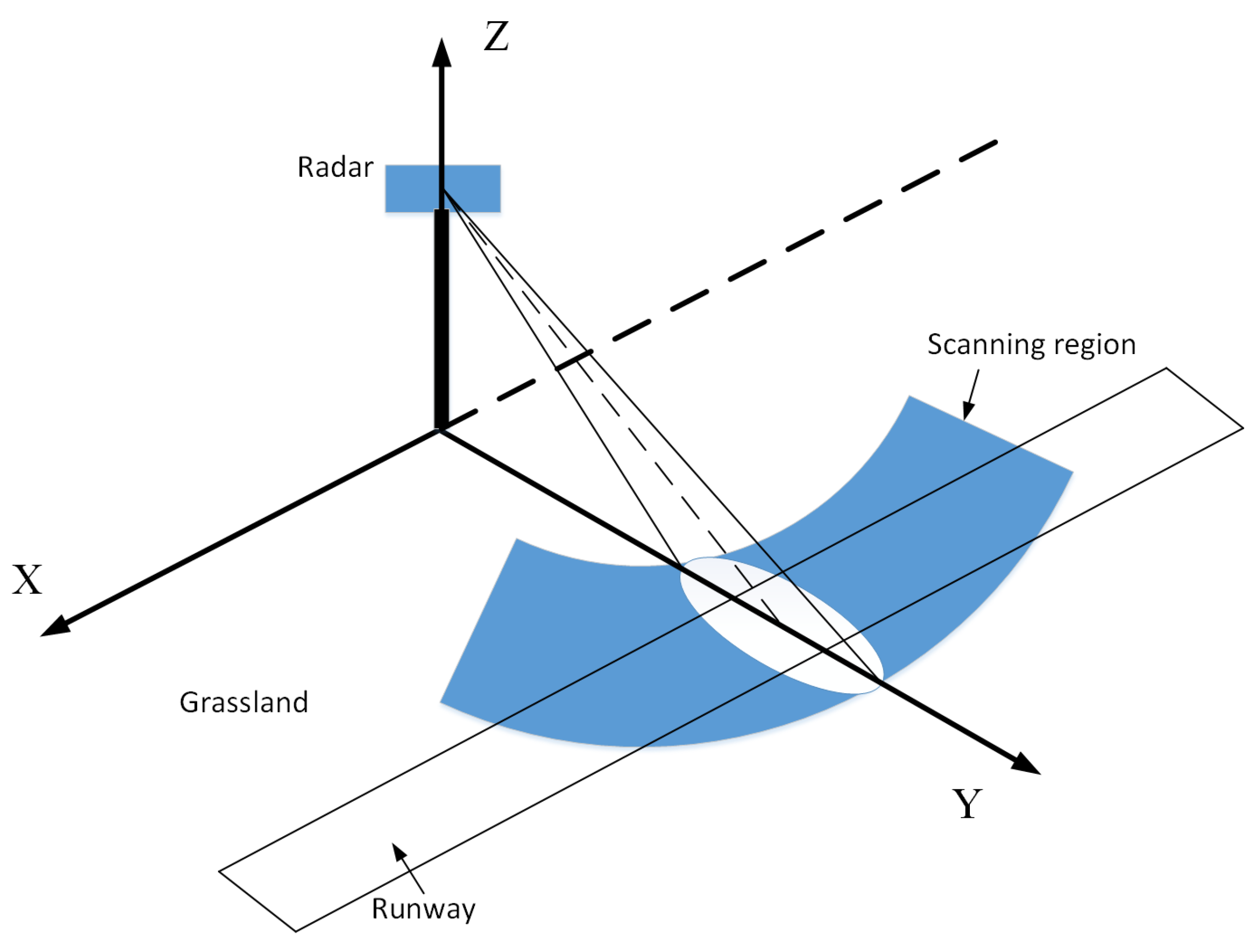
An FOD millimeter-wave detection radar is generally deployed on both sides of the runway, where the radar antenna scans and illuminates the rough runway surface. The geometric model of FOD millimeter-wave radar illumination is shown in Figure 1.
The radar needs to detect small foreign objects within a short distance, which requires the radar to have the smallest possible distance blind zone and higher range resolution. A millimeter-wave radar usually uses the linear frequency modulation continuous wave system, assuming that the transmitted signal is
where denotes the fast time, is the center frequency of the signal, is the frequency modulation rate of the chirp signal, B is frequency sweep bandwidth, T is frequency sweep cycle, and the target echo signals at different distances can be expressed as
where is the echo delay caused by the target, R is the target slant range, and c is the velocity of light. The difference frequency signal can be obtained after mixing and filtering the echo signal
where is the conjugate of , Equation (3) is the “matched filter” processing of the LFMCW. This signal is a single-frequency signal with a frequency of , where is the radar wavelength. After Fast Fourier Transform (FFT) processing, the range echo can be expressed as
Performing the time–frequency substitution of yields
After the range “matched filter” and Fast Fourier Transform (FFT) processing (we call it “range compression”), the range-azimuth two-dimensional echo signal can be expressed as
where t is the slow time, N is the number of range sampling points, and M is the number of azimuth sampling points, means the scatting amplitude of target located at ith range and jth azimuth bin, and is the antenna pattern modulation function.
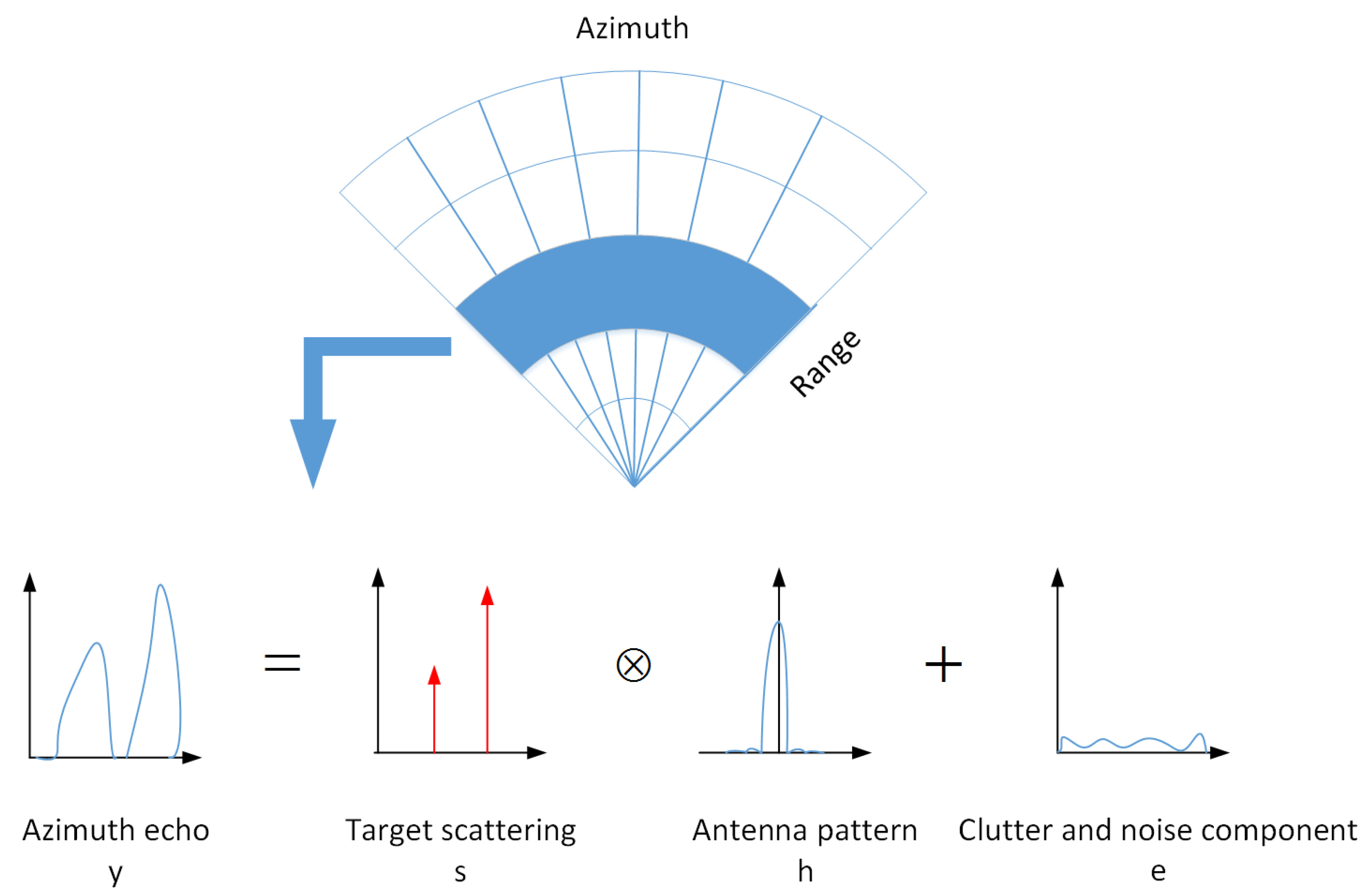
In scanning radar surface mapping, the azimuth echo can be regarded as the convolution result between the antenna pattern and the reflectivity function. The recorded echo data by radar is inevitably mixed with ground clutter and noise components, although clutter cancellation processing is performed before target detection. A signal model of the target azimuth echo for the scanning FOD millimeter-wave radar is shown in Figure 2. For each range unit, the discrete signal model of the target azimuth echo can be expressed as
where ⊗ is the convolution operation, s is the target scattering distribution, h is the antenna pattern, and e is the discrete clutter and additive noise component after clutter cancellation. This formula is equivalent to
where s is the target scattering vector defined as , suppose that there are K point targets, defines the antenna pattern vector, where represents transposition, and L is the number of antenna pattern sampling points. Furthermore, the steering vector matrix A can be defined as
where . The relationship among M, K, and L can be determined by
3. Detection Method
3.1. Interference Suppression and Super-Resolution Based on IAA
The iterative adaptive approach (IAA) is a non-parametric, weighted least squares-based iterative adaptive spectrum estimation approach. It can provide high resolution and low side-lobe levels in the case of a small number of snapshots, coherent sources, and low SNR [35]. Due to these advantages, the IAA has been applied to scanning radar sensing and demonstrated as outstanding, in terms of both resolution improvement and noise suppression. In the IAA framework [36], Equation (8) can be solved by weighted least squares (WLS) minimization. The WLS cost function is given by
where represents conjugate transpose, is the interference (signals at angles other than the angle of current interest k) covariance matrix
Define the covariance matrix of the echo and let P be a diagonal matrix, whose diagonal contains the power at each angle on the scanning grid. Then, P can be expressed as
Minimizing the cost function (10) with respect to yields
It can be seen, from the above formula, that a huge computational burden is required to calculate the value of , as recalculating is required in each step. Fortunately, by the matrix inversion lemma, can be expressed as
Inserting (15) into (14), the iterative formula for WLS estimation can be obtained as:
The azimuth echo is constructed by convolution of the antenna pattern and the target scattering coefficient, including the presence of noise. The signal recovery process is transformed into the corresponding inversion process. As the iteration proceeds, the IAA covariance matrix approaches a singular matrix and, so, its ill conditioning is inevitable. By adding regular terms, introducing prior information of noise or clutter distribution, and restoring the rank, the ill-conditioned problem can be handled. Some white noise is artificially added to the main diagonal of the echo data covariance matrix; namely, adaptive diagonal loading technology. This can ensure that the diagonal loading matrix is always invertible, regardless of whether the covariance matrix is singular or not. The covariance matrix of echo data can be expressed as
where is the diagonal loading factor and I is an identity matrix. According to the regularized IAA algorithm [26], the optimized parameters can be calculated by the following formula:
where M is the length of echo data and is the column of the identity matrix I.
The above-mentioned dispersive and residual interference mainly comes from the side-lobe of strongly scattering targets or non-homogeneous clutter after clutter cancellation processing. We use the adaptive iteration of the IAA algorithm to estimate the part of the interference component during each iteration and eliminate its influence from the measured data, thereby achieving interference suppression. The interference suppression and super-resolution algorithm based on IAA is implemented in an iterative manner, as described in Algorithm 1. Usually, the initialization is done by a standard delay-and-sum beamformer [35] that is, . When the difference between two adjacent estimated powers is calculated to be less than a certain threshold or a prescribed number of iterations is reached, the estimate of is obtained.
| Algorithm 1 Interference suppression and super-resolution algorithm based on IAA |
| Initialization: |
| Repeat |
| fork = 1, 2, …, K |
| end for |
| until (convergence) |
3.2. FOD Detection Method
Traditional FOD detection methods only use the background clutter to cancel the clutter of the observed scene, which makes it impossible to completely eliminate the clutter and interference reflections. The proposed method combines the clutter cancellation together, while exploiting the sparsity of the observed scene and distribution characteristics of interference. The dispersed interference reflections can be suppressed under the process of IAA reconstruction.
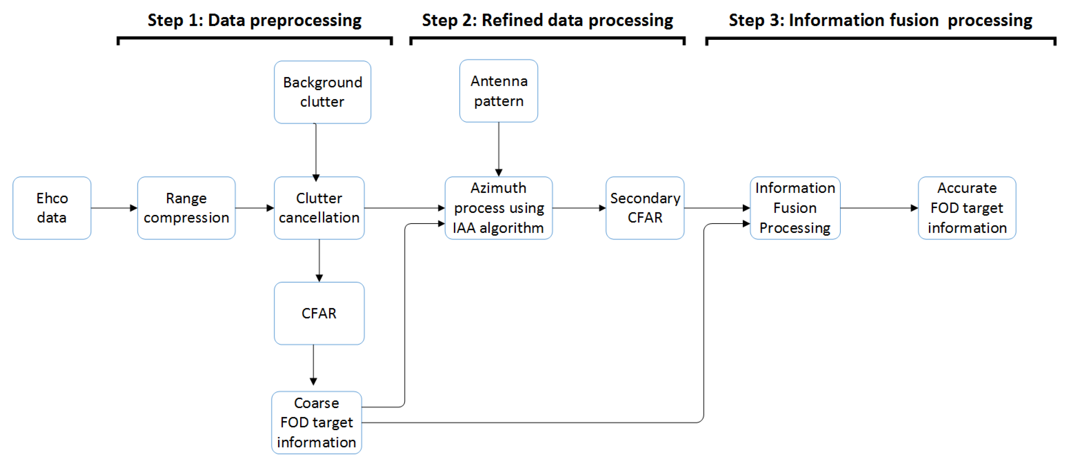
Based on the existing FOD detection algorithm, we propose an FOD detection method based on IAA signal reconstruction. The method is divided into three steps: data preprocessing, refined data processing, and information fusion processing. Finally, accurate FOD target information (coordinate information on the runway) can be obtained.
Specific descriptions of the steps are as follows:
- Step 1:
- Data preprocessing. First, the estimation of clutter background intensity is obtained by averaging the measured values of previous multiple scans of the runway scene without targets. After iterative averaging, the clutter map storage value becomes more and more stable, and the clutter change amplitude becomes smaller and smaller, which can reduce the false alarm rate. The adaptive clutter map CFAR technology is used to obtain the coarse FOD target information. This is the general detection method of conventional FOD radar.
- Step 2:
- Refined data processing. First, use standard instruments to acquire the radar antenna pattern data by far field measurement method, which can be normalized for subsequent processing. Then, according to the coarse FOD target information obtained in Step 1, the original data of the same range bin corresponding to the FOD target position will be reprocessed by IAA in the azimuth direction. Finally, the CFAR detection processing is performed again.
- Step 3:
- Information fusion processing.Through the processing of the above two steps, the coarse FOD target information obtained by Step 1 and the second detection FOD target information acquired by Step 2 are used to comprehensively distinguish false alarms by fusion processing of multiple information, in order to obtain accurate FOD target information.
The specific flow chart is shown in Figure 3. This article focuses on the IAA processing part of Step 2.
4. Experimental Scenarios
To validate the effectiveness of the method proposed in this paper, some experimental results using FOD millimeter-wave radar data from the Aerospace Information Research, Chinese Academy of Sciences (AIRCAS) are presented. We performed our experiment using real Airport data. In the following, we introduce the radar sensor and test scenarios.
4.1. Radar Sensor
The test radar was a W-band linear frequency modulation continuous wave radar with a repetition frequency of 1000 Hz. The radio-frequency (RF) signals with a bandwidth of 2 GHz from 92 GHz to 94 GHz were downsampled into an intermediate-frequency (IF) band and loaded via an AD converter with sampling frequency of 50 MHz. The radar was mounted on a mechanical servo motor, in order to achieve azimuth scanning. A photo of the radar is shown in Figure 4a.
The antenna adopted a pair of horizontally polarization-fed parabolic antennae and scanned horizontally across an angular range of 360 degrees (according to this test scenario, we set the scan angle range from −40 degrees to +70 degrees). The basic function of the antenna is to complete signal transmission and reception. The transceiver antenna was separated to improve the isolation. According to the performance requirements of the system, an offset-fed parabolic antenna was used, with the transceiver antenna having the same form. The main-lobe beamwidth of the antenna was 4 degrees in elevation and 0.6 degree in azimuth. The narrow azimuthal beamwidth and wide elevation beamwidth make this antenna practical for FOD detection. Figure 4b shows the measured azimuth radiation pattern of the antenna at 93 GHz. The working parameters of the FOD millimeter-wave radar system are given in Table 1.
4.2. Test Scenarios
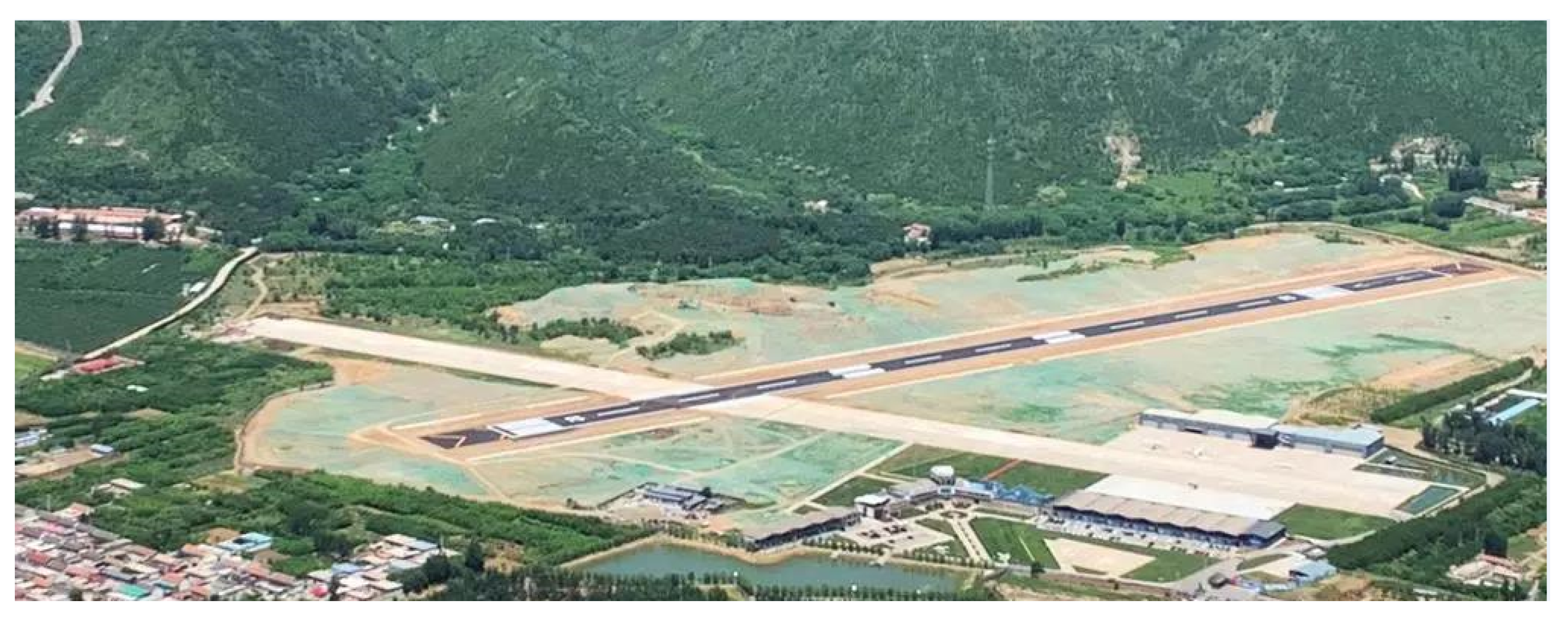
We performed our experiment at Beijing Miyun Airport, located in the northeast of the Beijing Miyun District. The new airport runway (asphalt material) and the crossed old runway (concrete material) are both 800 m in length. Figure 5 shows a photo of the airport.
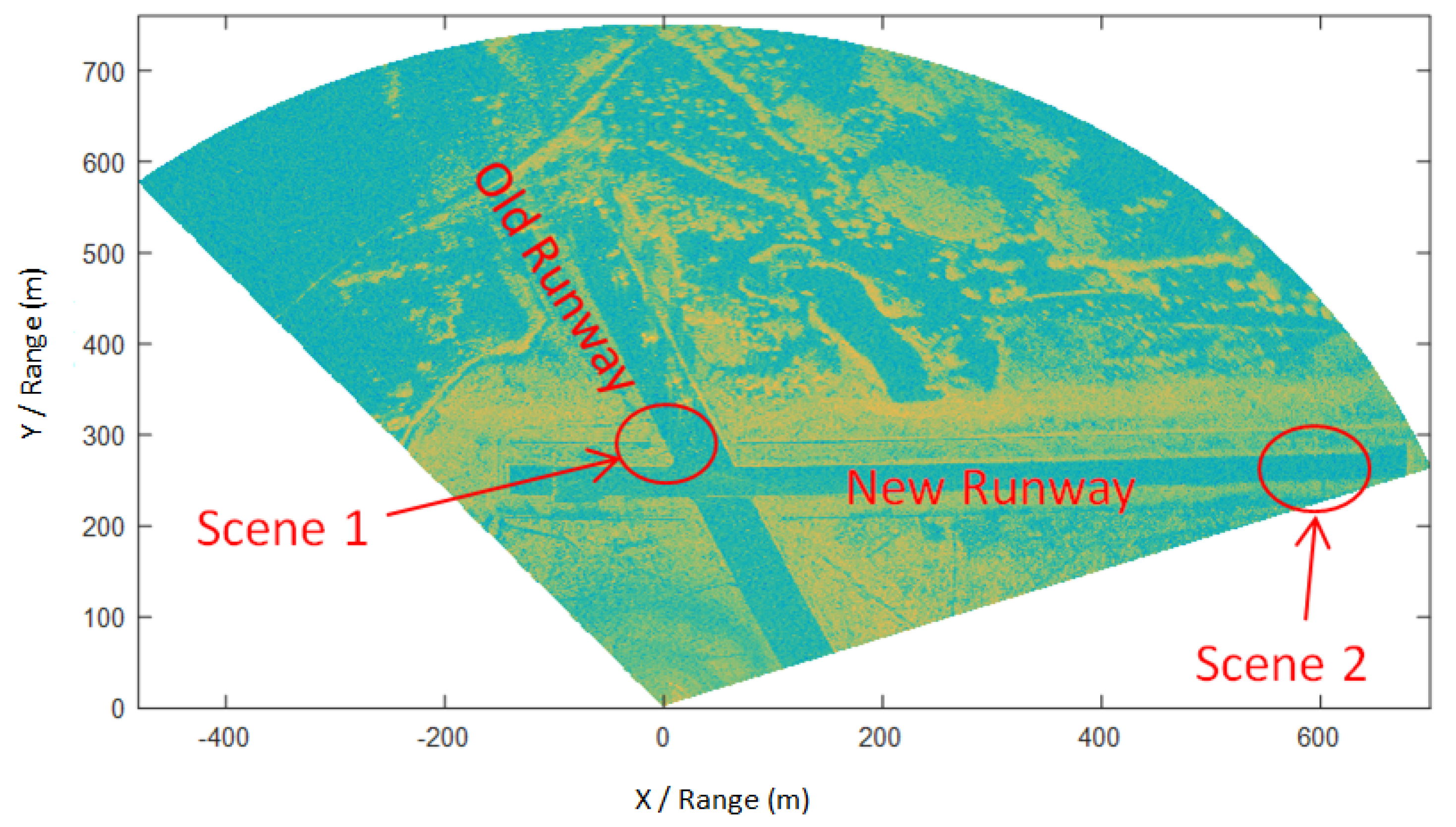
The test radar was placed about 250 m from the center line of the new runway, with the radar antenna about 9 m above the ground—after clearing the runway and manually confirming that there were no FODs in the test scene. The original echo data of the entire airport was acquired by scanning the airport. After range compression processing, the center of the radar antenna was used as the co-ordinate origin. Then, a radar amplitude image of the entire airport could be obtained, which can be used as the background clutter for clutter cancellation processing, as shown in Figure 6.
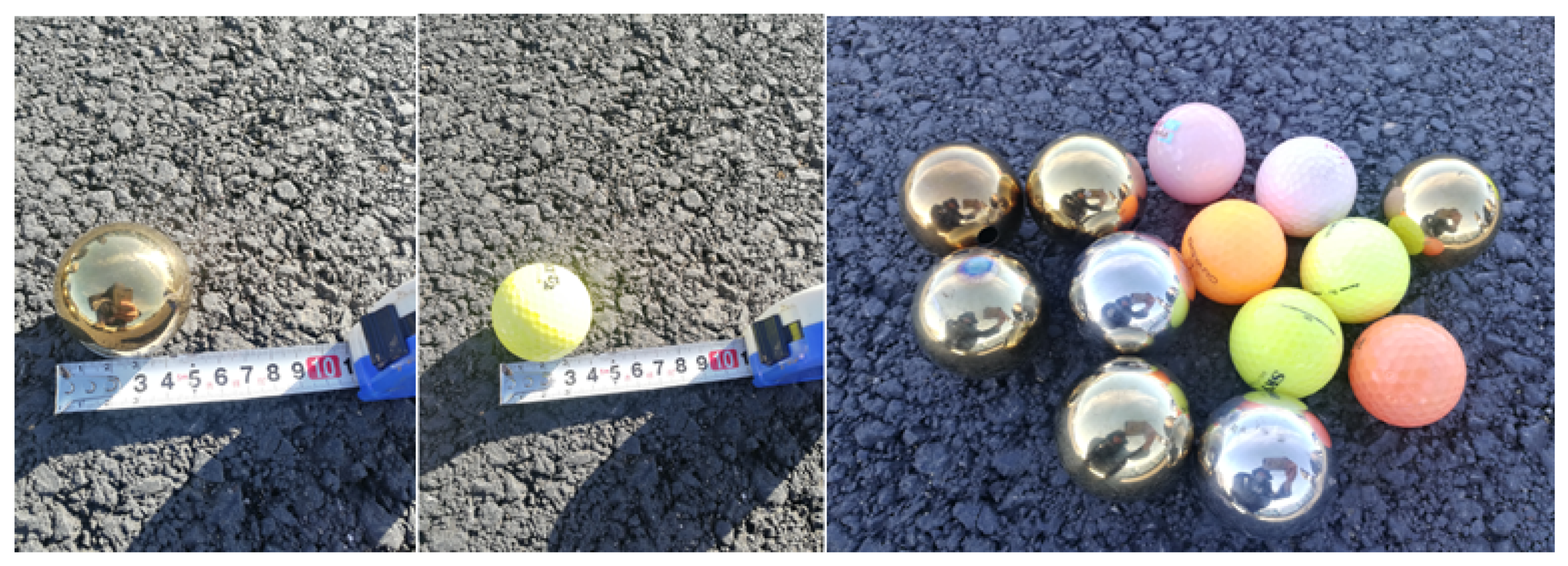
In order to verify the interference suppression and super-resolution improvement of FOD radar detection by the proposed IAA algorithm, we selected two test scenarios, the locations of which are marked in Figure 6. Scene 1 was located on the old runway. Six golf balls with a diameter of 43 mm were placed around the co-ordinates (100 m, 300 m) and near the aircraft parked on the runway, three of which were in the same range bin. Scene 2 was located on the new runway, where seven metal balls with a diameter of 50 mm were placed around the co-ordinates (660 m, 250 m). Figure 7 shows the FOD targets used in the experiment.
5. Results and Discussion
5.1. Scene 1
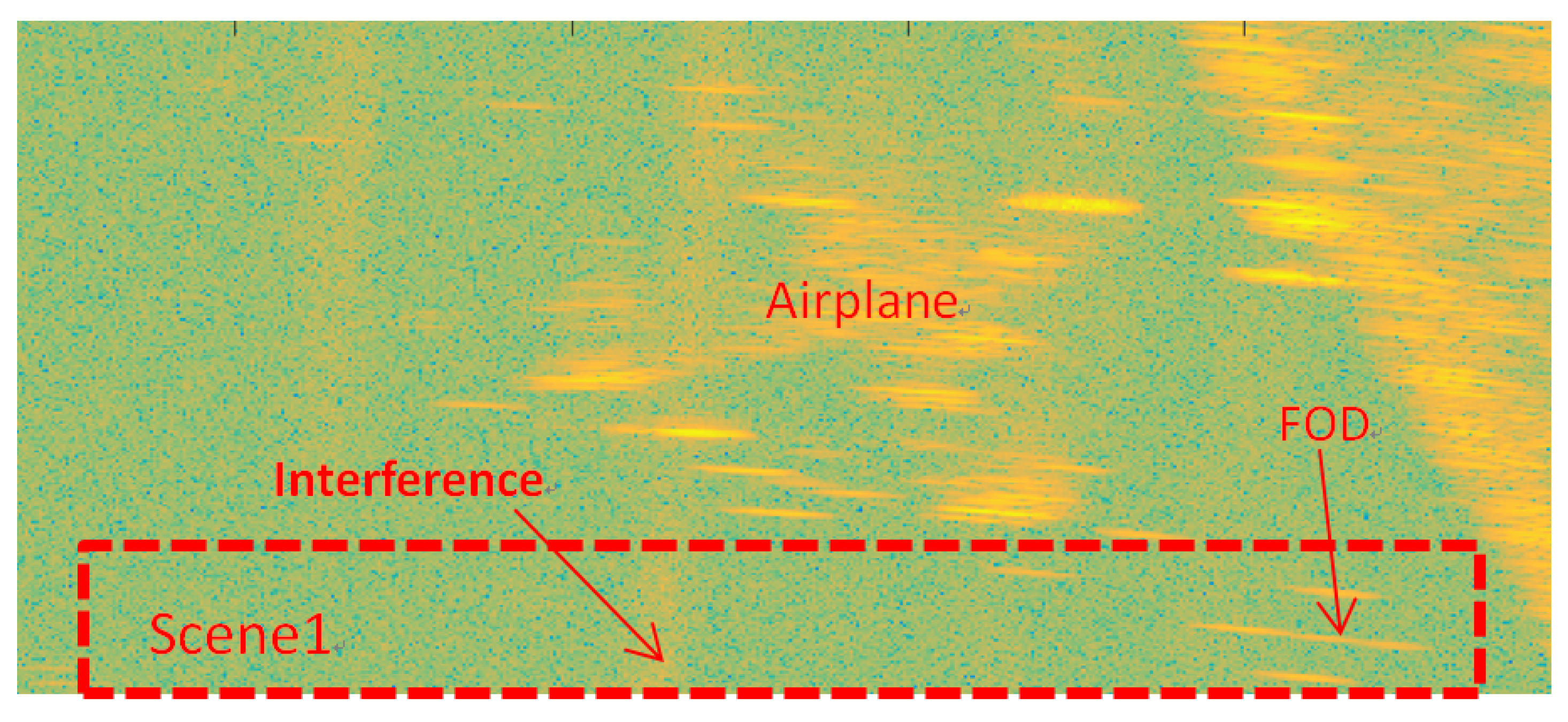
Figure 8 shows the amplitude image of the test Scene 1 after clutter cancellation processing. It can be seen that the strong echoes generated by airplane targets and grass could not be completely eliminated by clutter cancellation processing, with its side-lobes forming clutter interference resulting in false alarms, as shown in Figure 9. At the same time, there were many discrete clutter residues around the targets, which led to unnecessary false targets. Due to the poor azimuth resolution of the real aperture radar, it is obvious that the three close targets could not be distinguished.
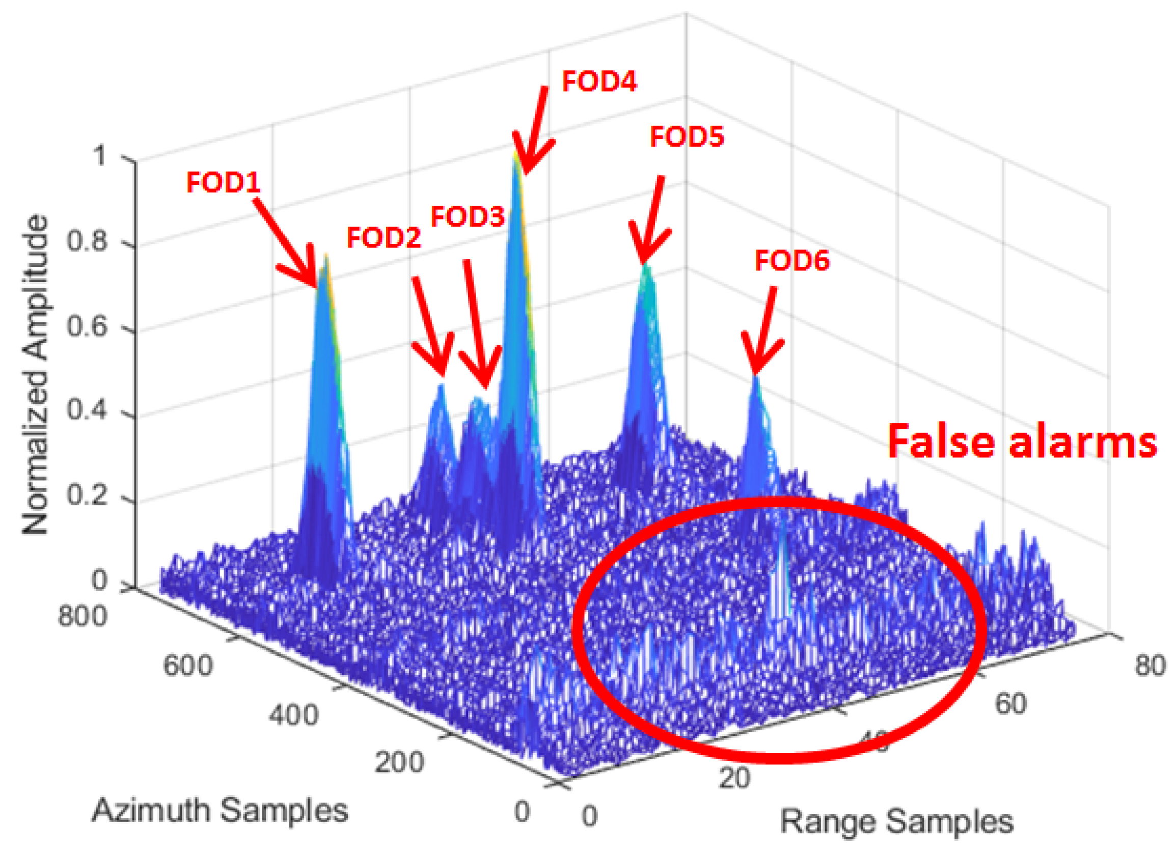
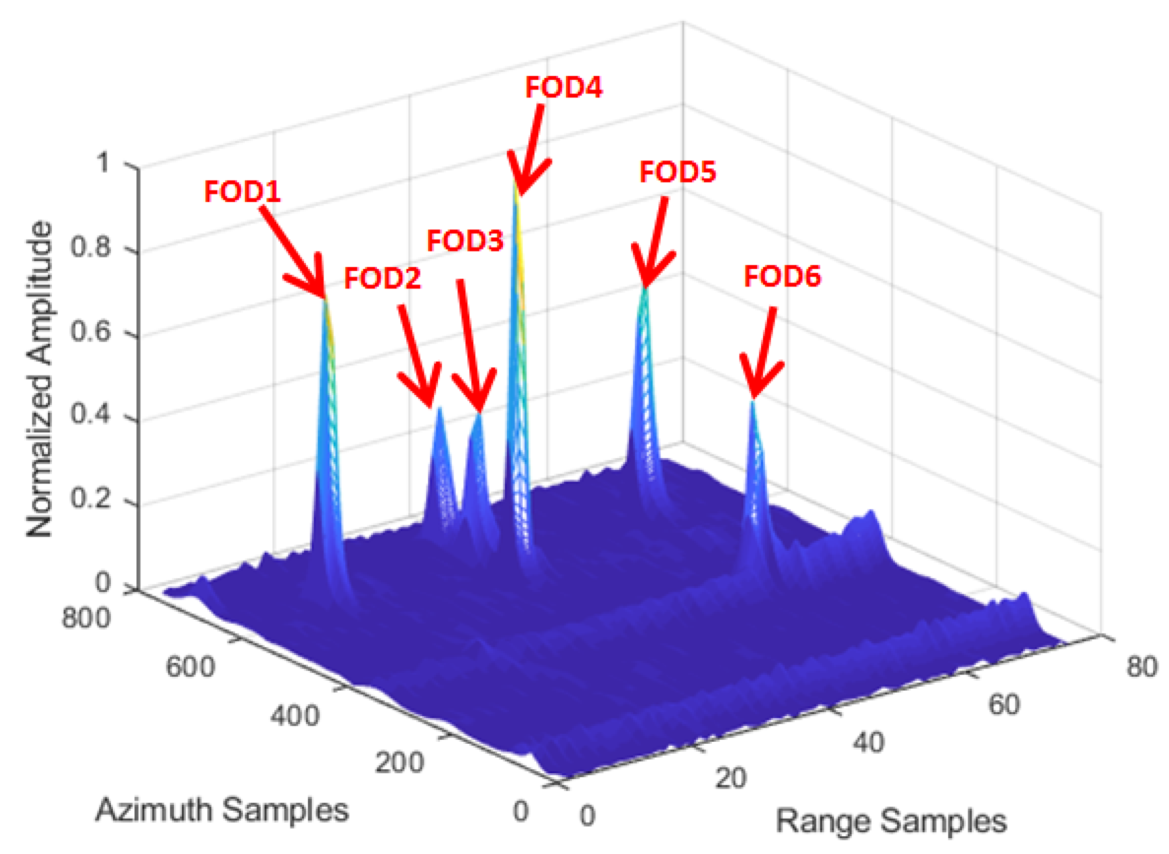
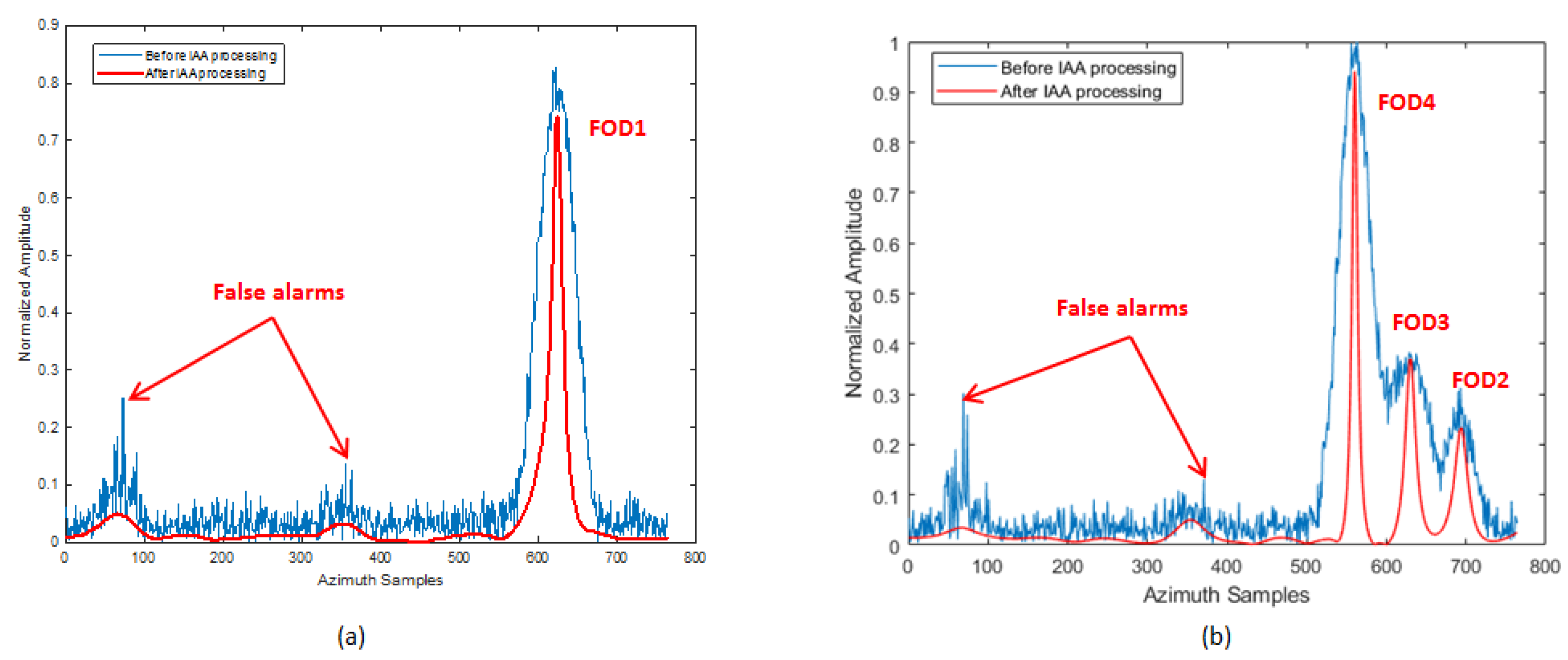
According to the FOD Detection Method described in Section 3, the original data of the same range bin corresponding to the FOD target position were reprocessed by IAA in the azimuth direction for the refined data processing step. We used the known antenna reference pattern and azimuth echo data to reconstruct the signal based on IAA algorithm in the target area. Through IAA processing, it can be seen that the clutter and interference signals were suppressed, and signals overlapping in azimuth were also distinguished, as can be seen in Figure 10. In order to reveal the effect more clearly, Figure 11 shows the results of before and after the IAA processing of azimuth data in the same 14th and 37th range bins. It can be clearly seen, from the figure, that a group of interferences located near the 50th azimuth sampling point was suppressed. This was the side-lobe interference from the aircraft target. However, FOD 2 was retained and recovered, whose signal power was the same as the interference. At the same time, the single discrete interferences located near azimuth sampling point 371 were suppressed, as shown in Figure 11b, which were considered residual interference after the clutter cancellation. In summary, while the false alarms were eliminated, the clutter background was also simultaneously smoothed. The azimuth resolution of the targets was improved. The super-resolution performance is uniformly analyzed below.
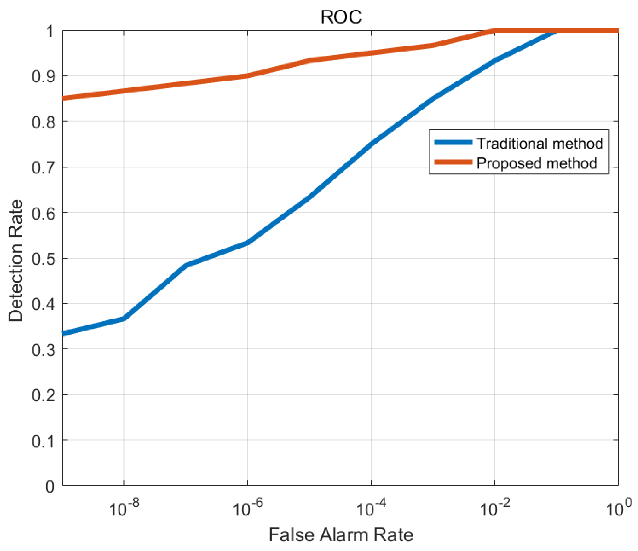
After data processing based on IAA, CFAR detection processing was performed once more. The same cell averaging (CA) CFAR was used, with five guard cells in range and 50 guard cells in azimuth. Receiver operating characteristic (ROC; detection rate versus false alarm rate) analysis has been widely used as an evaluation tool for signal detection [37]. In order to evaluate the performance of the two methods, comparison of the ROC curves of the traditional and proposed detection method is shown in Figure 12. When the same false alarm probability parameter was set, the proposed method had higher detection probability. In other words, it provided a much lower false alarm rate. Meanwhile, the detection performance was more stable under different false alarm probabilities. In short, the results show that the detection performance of the method proposed in this article was significantly better than that of the traditional method.
5.2. Scene 2
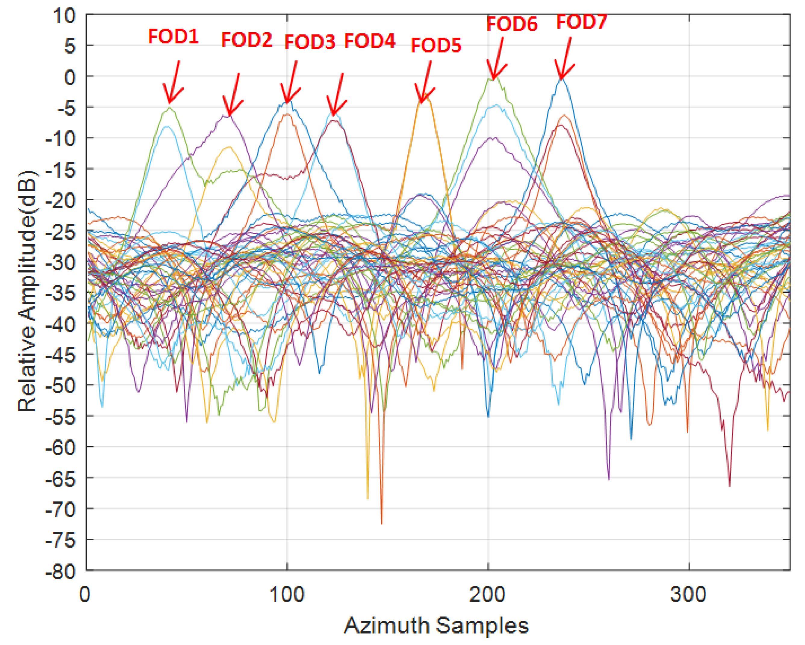
Compared with the close range scene, the clutter was weaker in the long range test scene. There were almost no false alarms, but, due to the poor azimuth resolution of the radar, it could not be distinguished completely along the azimuth direction in Figure 13. The azimuth resolution of the real aperture scanning radar is related to the azimuth beam width of the antenna and the target distance; in particular, as the distance increases, the resolution decreases.
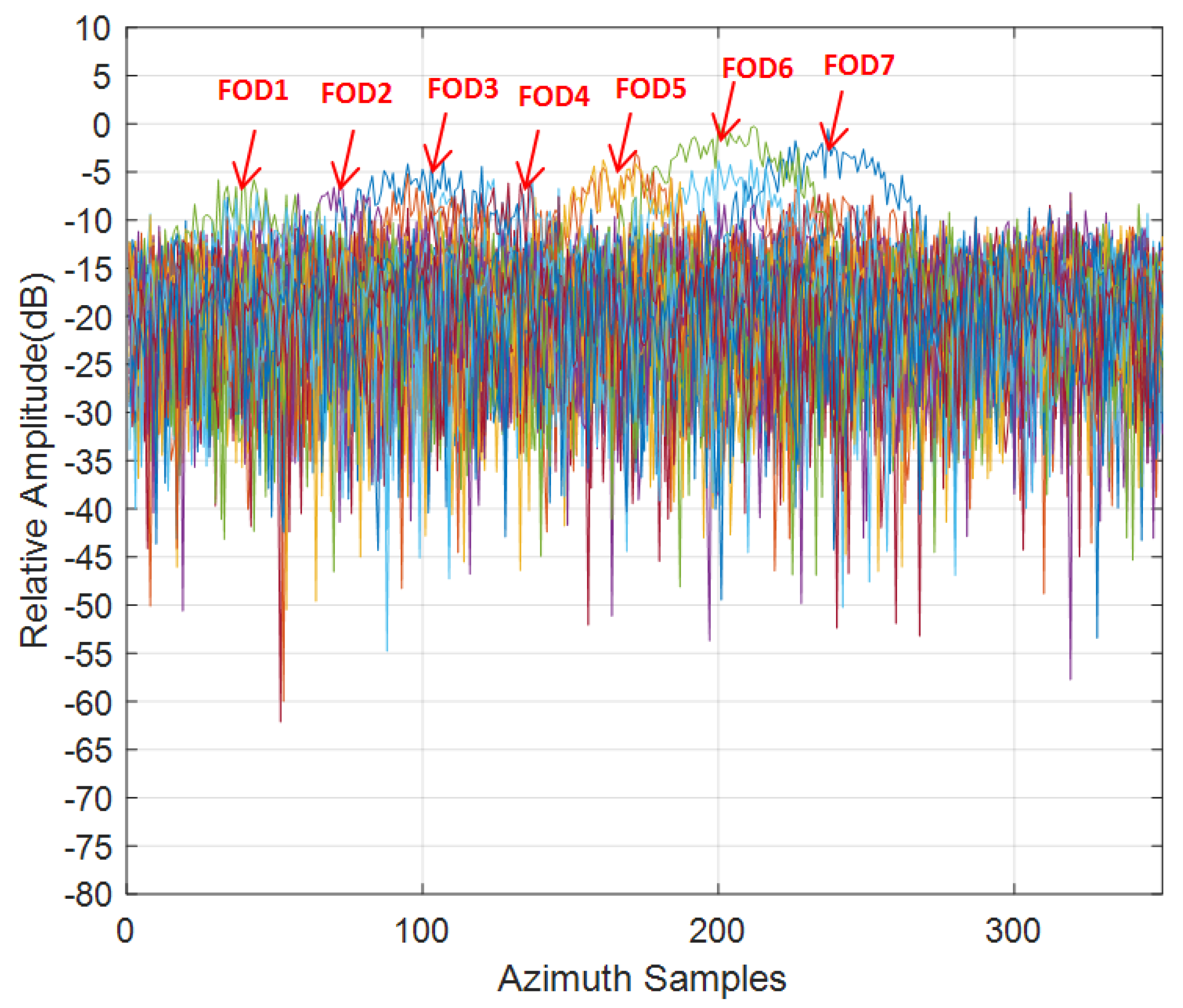
As the target was about 660 m away from the radar, the azimuth resolution was very poor. As can be seen from Figure 14, the overall clutter and noise level were relatively high, the SNR of the targets did not exceed 16 dB, and all targets were difficult to distinguish in the azimuth direction, leading to serious azimuth ambiguity. The IAA processing showed good azimuth super-resolution capability and suppression of the clutter background by about 10 dB, as shown in Figure 15. For FOD 5∼7 targets, as the signal-to-noise ratio was relatively higher, the reconstructed signal was smoother and the resolution effect was better, compared with the other FOD targets. To study the performance of super-resolution in this FOD detection method proposed, the super-resolution performance was evaluated using the super-resolution ratio, which is defined as [38]:
where is the main lobe width of the antenna pattern, which is equal to the azimuth resolution of the real beam imaging. had 3 dB width for the IAA estimates for a single FOD target. As determined through the calculation of each target in the scene, the super-resolution ratio statistics are listed in Table 2 and Table 3. The overall super-resolution performance of the FOD targets in Scene 1 was better than that of the FOD targets in Scene 2, where the FOD 4 target had the best super-resolution performance (of 3.1 times), benefiting from its high SNR. In Scene 2, the SNR was generally low (even down to 8 dB); however, a resolution performance of about 1.3 times was still obtained. These statistical results confirm that the IAA algorithm can maintain better performance at a lower SNR and, at the same time, as the SNR increases, the method’s performance increases [31,39].
Based on the analysis above, we have reason to believe that the method proposed in this paper not only possesses superior interference suppression capability, leading to false alarm reduction, but also can provide super-resolution in the azimuth direction.
6. Conclusions
In this article, a novel interference suppression and false alarm reduction method for a FOD millimeter-wave radar system was proposed, based on an iterative adaptive approach algorithm. The geometric and signal models of the real aperture FOD scanning radar were described. Next, the detection method based on IAA was derived in detail. Specifically, we first obtain coarse FOD target information by data preprocessing in a conventional detection method. Then, a refined data processing step is conducted based on the IAA algorithm in the azimuth direction. Finally, multiple pieces of information from the two steps above are used to comprehensively distinguish false alarms by fusion processing; thus, we can acquire accurate FOD target information. Real airport data measured by a 93 GHz radar are used to validate the proposed method. Experimental results of the test scene, which include golf balls with a diameter of 43 mm, were placed about 300 m away from radar, which show that the proposed method can effectively reduce the number of false alarms when compared with a traditional FOD detection method. Although metal balls with a diameter of 50 mm were placed about 660 m away from radar, they also can obtain up to 2.2 times azimuth super-resolution capability. Overall, the results demonstrated that the proposed method can effectively reduce false alarms and achieve super-resolution capability.
The IAA method has its limitations in some application scenarios, such as closely-spaced four targets and so on. How to improve and optimize its performance is an important work in the future. Recently, a new approach using Independent Component Analysis (ICA) with the Joint Approximate Diagonalization of Eigenmatrices (JADE) algorithm was used for separating closely-spaced subjects, such as respiratory signatures [40,41]. The research demonstrates that this approach can maintain accurate and efficient monitor multiple subjects across a broad range of subject separation scenarios [41]. Blind source separation (ICA-JADE) technology is a potential solution for a closely-spaced multiple targets separation in FOD detection. It may encourage further development toward a super-resolution FOD radar system.
Author Contributions
Conceptualization, Y.W., X.B. and Y.L.; investigation, Y.W.; methodology, Y.W.; resources, X.B. and Y.L.; writing—original draft preparation, Y.W.; writing—review and editing, X.B. and X.L.; project administration, X.L. All authors have read and agreed to the published version of the manuscript.
Funding
This research received no external funding.
Institutional Review Board Statement
Not applicable.
Informed Consent Statement
Not applicable.
Data Availability Statement
Not applicable.
Acknowledgments
The authors would like to thank the anonymous reviewers for their valuable comments and suggestions.
Conflicts of Interest
The authors declare no conflict of interest.
References
- Foreign Object Debris Detection Equipment, Document Advisory Circular; (AC)150/5220-24; Federal Aviation Administration: Washington, DC, USA, September 2009. Available online: https://www.faa.gov/documentLibrary/media/Advisory_Circular/AC_150_5220-24.pdf (accessed on 20 April 2017).
- Mazouni, K.; Zeitler, A.; Lanteri, J.; Pichot, C.; Dauvignac, J.; Migliaccio, C.; Yonemoto, N.; Kohmura, A.; Futatsumori, S. 76.5 GHz millimeter-wave radar for foreign object debris detection on airport runways. In Proceedings of the 2011 8th European Radar Conference, Manchester, UK, 12–14 October 2011; pp. 222–225. [Google Scholar]
- Feil, P.; Menzel, W.; Nguyen, T.P.; Pichot, C.; Migliaccio, C. Foreign objects debris detection (fod) on airport runways using a broadband 78 GHz sensor. In Proceedings of the 2008 38th European Microwave Conference, Amsterdam, The Netherlands, 27–31 October 2008; pp. 1608–1611. [Google Scholar]
- Mazouni, K.; Kohmura, A.; Futatsumori, S.; Yonemoto, N.; Dauvignac, J.Y.; Pichot, C.; Migliaccio, C. 77 GHz fm-cw radar for fods detection. In Proceedings of the 7th European Radar Conference, Paris, France, 30 September–1 October 2010; pp. 451–454. [Google Scholar]
- Brown, A.K. A review of radar as a sensor for advanced surface movement guidance and control systems (A-SMGCS). In Proceedings of the IEE Aviation Surveillance Systems, London, UK, 23 January 2002. [Google Scholar]
- Mehdi, G.; Miao, J. Millimeter wave fmcw radar for foreign object debris (fod) detection at airport runways. In Proceedings of the 2012 9th International Bhurban Conference on Applied Sciences & Technology (IBCAST), Islamabad, Pakistan, 9–12 January 2012; pp. 407–412. [Google Scholar]
- Guo, J.; Luo, Y.; Sui, Y.F.; Yan, D.Q.; Zhong, Q. Airport runway fod detection from lfmcw radar and image data. In Applied Mechanics and Materials; Trans Tech Publications Ltd.: Stafa, Switzerland, 2015; Volume 719, pp. 1124–1131. [Google Scholar]
- Futatsumori, S.; Morioka, K.; Kohmura, A.; Okada, K.; Yonemoto, N. Design and field feasibility evaluation of distributed-type 96 GHz fmcw millimeter-wave radar based on radio-over-fiber and optical frequency multiplier. J. Lightwave Technol. 2016, 34, 4835–4843. [Google Scholar] [CrossRef]
- Zhang, J.; Zheng, C.; Yang, B.; Yao, X.; Miao, J. Design procedures and considerations of fod detection millimeter-wave fmcw radar. In Proceedings of the 2013 IEEE International Conference on Green Computing and Communications and IEEE Internet of Things and IEEE Cyber, Physical and Social Computing, Beijing, China, 20–23 August 2013; pp. 1612–1617. [Google Scholar]
- Conte, E.; Longo, M.; Lops, M. Performance analysis of ca-cfar in the presence of compound gaussian clutter. Electron. Lett. 1988, 24, 782–783. [Google Scholar] [CrossRef]
- Zhang, Z.; Wang, Y.; Zhong, Q.; Li, H.; Yu, X. Performance analysis and comparison of cfar methods for fod detection in airport runway environment. In Proceedings of the 2015 International Conference on Communications, Signal Processing, and Systems; Springer: Berlin/Heidelberg, Germany, 2016; pp. 443–451. [Google Scholar]
- Han, Y.I.; Kim, T. Performance of excision go-cfar detectors in nonhomogeneous environments. IEE Proc. Radar Sonar Navig. 1996, 143, 105–112. [Google Scholar] [CrossRef]
- Levanon, N. Detection loss due to interfering targets in ordered statistics cfar. IEEE Trans. Aerosp. Electron. Syst. 1988, 24, 678–681. [Google Scholar] [CrossRef] [Green Version]
- Sciotti, M.; Lombardo, P. Performance evaluation of radar detection schemes based on ca-cfar against k-distributed clutter. In Proceedings of the 2001 CIE International Conference on Radar Proceedings (Cat No.01TH8559), Beijing, China, 15–18 October 2001; pp. 345–349. [Google Scholar]
- Jin, E.; Yan, D.; Zhang, Z.; Zhong, Q.; Yu, X. Fod detection on airport runway with clutter map cfar plane technique. In Communications, Signal Processing, and Systems; Springer: New York, NY, USA, 2012. [Google Scholar]
- Nitzberg, R. Clutter map cfar analysis. IEEE Trans. Aerosp. Electron. Syst. 1986, 22, 419–421. [Google Scholar] [CrossRef]
- Meng, X. Performance analysis of nitzberg’s clutter map for weibull distribution. Digit. Signal Process. 2010, 20, 916–922. [Google Scholar] [CrossRef]
- Naldi, M. False alarm control and self-masking avoidance by a biparametric clutter map in a mixed interference environment. IEE Proc. Radar Sonar Navig. 2002, 146, 195–200. [Google Scholar] [CrossRef]
- Wu, J.; Wang, H.; Yu, X.; Wang, X.; Zhao, M. CFAR detection method in multi-target environments for foreign object debris surveillance radar. In Lecture Notes in Electrical Engineering; Springer: Cham, Switzerland, 2014. [Google Scholar]
- Yang, X.; Huo, K.; Su, J.; Zhang, X.; Jiang, W. An anti-fod method based on ca-cm-cfar for mmw radar in complex clutter background. Sensors 2020, 20, 1635. [Google Scholar] [CrossRef] [PubMed] [Green Version]
- Wang, B.; Liu, J.; Zheng, X.; He, M.; Xiao, Q. A hierarchical fod detection method based on eigenvalue spectrum features. J. Electron. Inf. Technol. 2017, 39, 2690–2696. [Google Scholar]
- Wang, B.; Zhu, L.; Li, Z.; Wang, X.; Hu, H. A hierarchical foreign object debris detection method using millimeter wave radar. J. Electron. Inf. Technol. 2018, 40, 2676–2683. [Google Scholar]
- Lai, Y.-K. Foreign object debris detection method based on fractional fourier transform for millimeter-wave radar. J. Appl. Remote Sens. 2020, 14, 016508. [Google Scholar] [CrossRef]
- Ni, P.; Miao, C.; Tang, H.; Jiang, M.; Wu, W. Small foreign object debris detection for millimeter-wave radar based on power spectrum features. Sensors 2020, 20, 2316. [Google Scholar] [CrossRef] [Green Version]
- Yardibi, T.; Li, J.; Stoica, P.; Xue, M.; Baggeroer, A.B. Source localization and sensing: A nonparametric iterative adaptive approach based on weighted least squares. IEEE Trans. Aerosp. Electron. Syst. 2010, 46, 425–443. [Google Scholar] [CrossRef]
- Roberts, W.; Stoica, P.; Li, J.; Yardibi, T.; Sadjadi, F.A. Iterative adaptive approaches to mimo radar imaging. IEEE J. Sel. Top. Signal Process 2010, 4, 5–20. [Google Scholar] [CrossRef]
- Chai, H.; Lv, X. Sar tomography for point-like and volumetric scatterers using a regularised iterative adaptive approach. Remote Sens. Lett. 2018, 9, 1060–1069. [Google Scholar] [CrossRef]
- Zhang, Y.; Li, W.; Huang, Y.; Zhang, Y.; Yang, J. Two-channel iterative adaptive approach for scanning radar angular superresolution. In Proceedings of the 2016 IEEE Radar Conference (RadarConf), Philadelphia, PA, USA, 2–6 May 2016. [Google Scholar]
- Zhang, Y.; Jakobsson, A.; Yang, J. Range-recursive iaa for scanning radar angular super-resolution. IEEE Geosci. Remote Sens. Lett. 2017, 14, 1675–1679. [Google Scholar] [CrossRef]
- Wang, Y.; Zhang, Y.; Huang, Y.; Li, W.; Yang, J.; Yang, H. Advantages and challenges of power spectral density estimation methods for scanning radar angular superresolution. In Proceedings of the 2015 IEEE International Geoscience and Remote Sensing Symposium (IGARSS), Milan, Italy, 26–31 July 2015. [Google Scholar]
- Zhang, Y.; Zhang, Y.; Huang, Y.; Li, W.; Yang, J. Angular superresolution for scanning radar with improved regularized iterative adaptive approach. IEEE Geosci. Remote Sens. Lett. 2016, 13, 846–850. [Google Scholar] [CrossRef]
- Zhang, Y.; Zhang, Y.; Li, W.; Huang, Y.; Yang, J. Super-resolution surface mapping for scanning radar: Inverse filtering based on the fast iterative adaptive approach. IEEE Trans. Geosci. Remote 2017, 56, 127–144. [Google Scholar] [CrossRef]
- Zhang, Y.; Li, W.; Zhang, Y.; Huang, Y.; Yang, J. A fast iterative adaptive approach for scanning radar angular superresolution. IEEE J. Sel. Top. Appl. Earth Obs. Remote Sens. 2015, 8, 5336–5345. [Google Scholar] [CrossRef]
- Qi, L.; Yu, W.; Zheng, M.; Hou, L. Detection and parameter estimation of ground moving targets in multichannel wide-area surveillance system based on iterative adaptive approach. IET Radar Sonar Navig. 2016, 10, 1145–1152. [Google Scholar] [CrossRef]
- Qi, L.; Zheng, M.; Yu, W.; Li, N.; Hou, L. Super-resolution doppler beam sharpening imaging based on an iterative adaptive approach. Remote Sens. Lett. 2016, 7, 259–268. [Google Scholar] [CrossRef]
- Zhang, Y.; Zhang, Y.; Li, W.; Huang, Y.; Yang, J. Angular superresolution for real beam radar with iterative adaptive approach. In Proceedings of the 2013 IEEE International Geoscience and Remote Sensing Symposium (IGARSS2014), Melbourne, Australia, 21–26 July 2013. [Google Scholar]
- Petrov, N.; Le Chevalier, F.; Yarovoy, A. Detection of range migrating targets in compound-gaussian clutter. IEEE Trans. Aerosp. Electron. Syst. 2017, 54, 37–50. [Google Scholar] [CrossRef]
- Petrov, N.; Le Chevalier, F. Iterative adaptive approach for unambiguous wideband radar target detection. In Proceedings of the 2015 European Radar Conference (EuRAD), Paris, France, 9–11 September 2015; pp. 45–48. [Google Scholar]
- Glentis, G.O.; Jakobsson, A. Time-recursive iaa spectral estimation. IEEE Signal Process. Lett. 2010, 18, 111–114. [Google Scholar] [CrossRef]
- Islam, S.M.; Yavari, E.; Rahman, A.; Lubecke, V.M.; Boric-Lubecke, O. Separation of respiratory signatures for multiple subjects using independent component analysis with the jade algorithm. In Proceedings of the 2018 40th Annual International Conference of the IEEE Engineering in Medicine and Biology Society (EMBC), Honolulu, HI, USA, 18–21 July 2018. [Google Scholar]
- Islam, S.M.M.; Boric-Lubecke, O.; Lubekce, V.M. Concurrent respiration monitoring of multiple subjects by phase-comparison monopulse radar using independent component analysis (ica) with jade algorithm and direction of arrival (doa). IEEE Access 2020, 8, 73558–73569. [Google Scholar] [CrossRef]
Figure 1.
Geometry of FOD millimeter-wave radar illumination.

Figure 2.
Signal model of the target azimuth echo for the scanning FOD millimeter-wave radar.

Figure 3.
Flowchart of the FOD radar processing chain for the proposed method.

Figure 4.
Some details of FOD millimeter-wave radar: (a) radar appearance; and (b) measured antenna azimuth radiation pattern at 93 GHz.
Figure 4.
Some details of FOD millimeter-wave radar: (a) radar appearance; and (b) measured antenna azimuth radiation pattern at 93 GHz.

Figure 5.
Photo of Beijing Miyun Airport.

Figure 6.
Radar amplitude image of Beijing Miyun Airport.

Figure 7.
FOD targets used in the experiment.

Figure 8.
FOD targets deployment in Scene 1.

Figure 9.
Before IAA processing of the area of Scene 1.

Figure 10.
After IAA processing of the area of Scene 1.

Figure 11.
Comparison of IAA processing results for the same range bin: (a) before and after IAA processing of azimuth data on the 14th range bin of Scene 1; (b) before and after IAA processing of azimuth data on the 37th range bin of Scene 1.
Figure 11.
Comparison of IAA processing results for the same range bin: (a) before and after IAA processing of azimuth data on the 14th range bin of Scene 1; (b) before and after IAA processing of azimuth data on the 37th range bin of Scene 1.

Figure 12.
Comparison of ROC curves of the traditional and proposed detection methods.

Figure 13.
FOD target deployment, Scene 2.

Figure 14.
Test data obtained on azimuth direction, Scene 2.

Figure 15.
Results after azimuth IAA processing, Scene 2.


Table 1.
Parameters of the FOD millimeter-wave radar system.
| Parameter | Value | Units |
|---|---|---|
| Carrier frequency | 93 | GHz |
| Band width | 2 | GHz |
| Antenna scanning velocity | 15 | degrees/s |
| Azimuth main-lobe beamwidth | 0.6 | degree |
| Elevation main-lobe beamwidth | 4 | degrees |
| Antenna scanning area | −40∼+70 | degrees |
| Pulse repetition frequency | 1000 | Hz |
Table 2.
Super-resolution ratio statistics of the FOD targets in Scene 1.
| Target | FOD 1 | FOD 2 | FOD 3 | FOD 4 | FOD 5 | FOD 6 |
|---|---|---|---|---|---|---|
| 16.2 | 10.1 | 12.2 | 18.3 | 13.8 | 12 | |
| 2.2 | 2.1 | 2.4 | 3.1 | 2.1 | 2.6 |
Table 3.
Super-resolution ratio statistics of the FOD targets in Scene 2.
| Target | FOD 1 | FOD 2 | FOD 3 | FOD 4 | FOD 5 | FOD 6 | FOD 7 |
|---|---|---|---|---|---|---|---|
| 9.8 | 8 | 10 | 8.2 | 12.3 | 15.2 | 14 | |
| 1.8 | 1.3 | 1.4 | 2 | 2.2 | 1.7 | 2.2 |
Publisher’s Note: MDPI stays neutral with regard to jurisdictional claims in published maps and institutional affiliations. |
© 2021 by the authors. Licensee MDPI, Basel, Switzerland. This article is an open access article distributed under the terms and conditions of the Creative Commons Attribution (CC BY) license (http://creativecommons.org/licenses/by/4.0/).
Share and Cite
MDPI and ACS Style
Wan, Y.; Liang, X.; Bu, X.; Liu, Y. FOD Detection Method Based on Iterative Adaptive Approach for Millimeter-Wave Radar. Sensors 2021, 21, 1241. https://doi.org/10.3390/s21041241
AMA Style
Wan Y, Liang X, Bu X, Liu Y. FOD Detection Method Based on Iterative Adaptive Approach for Millimeter-Wave Radar. Sensors. 2021; 21(4):1241. https://doi.org/10.3390/s21041241
Chicago/Turabian StyleWan, Yangliang, Xingdong Liang, Xiangxi Bu, and Yunlong Liu. 2021. "FOD Detection Method Based on Iterative Adaptive Approach for Millimeter-Wave Radar" Sensors 21, no. 4: 1241. https://doi.org/10.3390/s21041241
Note that from the first issue of 2016, this journal uses article numbers instead of page numbers. See further details here.