


Visual/Inertial/GNSS Integrated Navigation System under GNSS Spoofing Attack
1
Department of Precision Instrument, Tsinghua University, Beijing 100084, China
2
State Key Laboratory of Precision Measurement Technology and Instruments, Tsinghua University, Beijing 100084, China
3
Beijing Advanced Innovation Center for Integrated Circuits, Beijing 100084, China
*
Author to whom correspondence should be addressed.
Remote Sens. 2022, 14(23), 5975; https://doi.org/10.3390/rs14235975
Submission received: 9 October 2022
/
Revised: 15 November 2022
/
Accepted: 23 November 2022
/
Published: 25 November 2022
(This article belongs to the Topic Artificial Intelligence in Sensors)
Abstract
:Visual/Inertial/GNSS (VIG) integrated navigation and positioning systems are widely used in unmanned vehicles and other systems. This VIG system is vulnerable to of GNSS spoofing attacks. Relevant research on the harm that spoofing causes to the system and performance analyses of VIG systems under GNSS spoofing are not sufficient. In this paper, an open-source VIG algorithm, VINS-Fusion, based on nonlinear optimization, is used to analyze the performance of the VIG system under a GNSS spoofing attack. The influence of the visual inertial odometer (VIO) scale estimation error and the transformation matrix deviation in the transition period of spoofing detection is analyzed. Deviation correction methods based on the GNSS-assisted scale compensation coefficient estimation method and optimal pose transformation matrix selection are proposed for VIG-integrated system in spoofing areas. For an area that the integrated system can revisit many times, a global pose map-matching method is proposed. An outfield experiment with a GNSS spoofing attack is carried out in this paper. The experiment result shows that, even if the GNSS measurements are seriously affected by the spoofing, the integrated system still can run independently, following the preset waypoint. The scale compensation coefficient estimation method, the optimal pose transformation matrix selection method and the global pose map-matching method can depress the estimation error under the circumstances of a spoofing attack.
1. Introduction
Positioning and navigation are basic problems in the autonomous operation of unmanned ground vehicles (UGVs), unmanned aerial vehicles (UAVs) and other intelligent systems. Positioning and navigation technology is an ancient and modern technology. With the development of sensor technology, a variety of navigation sensors with different physical principles have been utilized. One of the most important reasons that there are so many kinds of navigation sensors is that each kind of navigation sensor has particular technical advantages and disadvantages, so it is often necessary to combine different kinds of sensors to achieve complementary advantages. With the gradual maturity of each kind of navigation sensor technology and the reduction in costs, intelligent systems such as UVs and UAVs are often equipped with various navigation sensors to form integrated navigation and positioning systems. The most commonly used positioning and navigation technologies mainly include the Global Navigation Satellite System (GNSS), Inertial Navigation System (INS) [1], etc. With the development of computer vision, visual Simultaneous Localization Additionally, Mapping (SLAM) technology has gradually become an important positioning and navigation technology for intelligent systems [2].
GNSS is still the most important absolute positioning technology. The main advantage of GNSS systems is that they provide all-weather, high-precision, high-stability positioning results in outdoor environments in most parts of the world and most situations [3]. GNSS has stable long-term positioning accuracy, high technology maturity, low-volume power consumption and an extremely low cost for the navigation receiver of the client, and has a wide range of applications. However, most GNSS receivers are vulnerable to spoofing attacks [4]. The deviation errors of the localization results caused by spoofing will lead the system to a pre-set wrong location [5]. The positioning signal of the GNSS system is easy to imitate, so its security is worth attention. Shepard et al. [6] successfully demonstrated the spoofing of drones. Noh et al. [7] proposed a method of hijacking drones using GPS spoofing. GNSS spoofing could also influence the integrated positioning system of GNSS combined with other sensors, such as INS [8]. As the influence of GNSS spoofing on VIG systems has not been discussed in depth, this paper focuses on the performance of VIG-integrated systems under GNSS spoofing.
Inertial sensor is another important kind of sensors in the VIG system. Inertial measurement does not depend on external information, nor does it radiate energy to the outside [9]. It has high security, high short-term accuracy, and a high data update rate, and can be applied to some special environments, such as underground and underwater. The disadvantage of INS is that, because the navigation information is generated through integration, it can only provide relative positioning information, not absolute information. Moreover, the integration process will inevitably lead to the accumulation of positioning errors over time, resulting in poor long-term accuracy and high costs for high-precision inertial sensors. Visual SLAM also has the problem of accumulating positioning errors, but it does not have the problem of zero bias, and the errors are mostly accumulated due to motion. Therefore, the long-term accuracy of integrated systems can be significantly improved by combining an inertial sensor with a SLAM sensor. The combined use of visual/inertial odometry (VIO) can achieve the accuracy level of high-cost inertial sensors at a low cost [10].
The VIG system can combine the advantages of the three kinds of sensors, and these can complement each other to achieve absolute positioning with high accuracy, a high update rate and no cumulative error. Studies that combine visual SLAM technology with inertial and GNSS technology include VINS-Fusion [11] and GVINS [12]. Although many kinds of integrated algorithms have been discussed, the performance of these algorithms in some critical circumstances, such as GNSS spoofing, need further research. Spoofing has gradually become a research hotspot for satellite navigation interference technology [13].
GNSS spoofing signals are designed to mislead GNSS receivers [14]. References [15,16] utilized INS information to monitor GPS spoofing for aircraft. Reference [17] used tightly coupled INS/GNSS algorithms to counter GNSS spoofing. Reference [18] used the information of GNSS/IMU/odometry systems to detect GNSS spoofing. These pieces of research did not involve visual measurements and were not designed for nonlinear VIG systems. Reference [19] proposed a GPS spoofing detection method based on cameras, but this was also not designed for nonlinear VIG systems and did not discuss the positioning performance after GNSS spoofing identification.
In the previous study [20], the problem of the VINS-Fusion algorithm being induced by spoofing signals is discussed for the first time, and the vulnerability of the VIG-integrated algorithm without a specific anti-spoofing design is proven. Reference [21] also studied the characteristics of a visual SLAM/GNSS system under spoofing attack and proposed a Time-Localization Verification and Smoothing Localization Method (PTC-SLM) method to identify the spoofing and smooth the positioning solution. The PTC-SLM method analyzed the joint error offset from the GNSS from the dimensions of time and localization using visual SLAM estimations to identify GNSS spoofing, and selected the corresponding back-end optimization strategy to obtain a smoothing localization result. Dataset experiments were carried out with the KITTI dataset [22] in that study. Compared with the study in [21], the previous study [20] not only carried out KITTI dataset experiments, but also carried out a spoofing detection experiment in a real spoofing environment. Compared with the study in this paper, Reference [21] did not evaluate the SLAM/GNSS system in a real spoofing environment after GNSS spoofing detection.
Some methods related to this study have been discussed. Reference [23] discussed the robust initialization and online scale estimation of the visual/inertial odometry, but did not have GNSS measurements to correct the scale. Reference [24] proposed a method that used a map with weak GPS priors to correct the localization results of a repetitive UAV flight. Reference [25] treated the localization problem as a rigid base-frame alignment problem between a local map and a reference map. However, none of this research referred to the influence of spoofing.
The main purpose of study [20] is to verify the effectiveness of a GNSS spoofing detection algorithm assisted by visual/inertial information. The research on the characteristics and problems of VIG-integrated systems under spoofing is not sufficient. Experiment with VIG-integrated system in the spoofing environment are also not sufficient. The study in this paper will use the GNSS spoofing detection method proposed in a previous study [20], and discuss the performance and key problems of the VIG system based on the identification of GNSS spoofing.
The VIG system proposed in this study combines sensor hardware and a positioning algorithm. The positioning algorithm used in this study has three modules. One is a nonlinear optimization and positioning module, including the scale estimation methods and optimal transformation matrix selection method proposed in this paper. The second is the key frame global pose map-creating and matching module, also proposed in this paper. The final module is the spoofing detection module introduced in study [20]. The input of the system is visual/IMU/GNSS data and key frame data from the database. The framework structure of the VIG system in this paper is illustrated in Figure 1.
The main contributions of this paper can be summarized as follows:
- (1)
- To solve the problem of inaccurate scale estimation of the VIO under spoofing attack, a real-time scale compensation coefficient estimation method in a nonlinear optimization framework is proposed for the first time. GNSS measurements are used to estimate the scale compensation coefficient, helping to solve the problem of inaccurate pose estimation caused by inaccurate scale estimation when VIO is applied in a large-scale outdoor scenario.
- (2)
- For a revisit area, a VIG-integrated positioning algorithm, based on global pose map-matching, is proposed to accurately determine the pose of the system in a spoofing environment.
- (3)
- The experiment compares the difference in positioning accuracy between the two conditions without and with scale real-time estimation, and the two conditions without and with spoofing attack. It is proved that the real-time and high-precision estimation of the scale is the basis of the optimization-based VIG system operating in the spoofing environment.
- (4)
- Experiments under spoofing conditions show that the VIG navigation algorithm based on global pose map-matching has autonomous navigation and positioning abilities.
The rest of the paper is organized as follows. In Section 2, the scale compensation coefficient estimation method in the optimization-based VIG algorithm is introduced. Then, the key frame global pose map-matching method of the integrated navigation system in the revisit area under GNSS spoofing attack is introduced in Section 3. In Section 4, the optimal pose transformation matrix under the influence of spoofing is introduced. In Section 5, the algorithm proposed in this paper is tested and evaluated. Section 6 and Section 7 discuss and conclude this paper.
2. Scale Estimation of Visual/Inertial/GNSS-Integrated Algorithm
Scale factor refers to the scaling relationship between the VIO body coordinate system and the ENU world coordinate system. Under the ideal initialization conditions, the scale factor could be accurately recovered from the initialization process of the VIO [26], and directly used to obtain the transformation matrix from any frame to the world system in the subsequent estimation and localization. Therefore, the issue of scale was not taken into consideration when VIO and GNSS were fused in the VINS-Fusion algorithm [11] and other fusion algorithms. The problems in the theory analysis and experiment show that the precision of the VIO scale estimation will seriously affect the integrated positioning result under spoofing circumstances. In this section, the influence of VIO scale estimation errors on positioning accuracy is discussed, and a real-time estimation method is proposed for the nonlinear optimization of scale compensation coefficients in the fusion of VIO and GNSS.
2.1. The Influence of VIO Scale Estimation Errors on the Positioning Accuracy
In the optimization-based integrated algorithm such as VINS-MONO [26] and ORB-SLAM3 [27], the estimation of the scale factor is obtained by optimizing the cost function of the VIO. However, the scale of monocular VO could not accurately be determined, such as ORB-SLAM [28] and ORB-SLAM2 [29]. When the initialization of VINS-MONO is completed, the scale factor is also determined, so the estimation accuracy of the scale factor depends on the initialization conditions. When binocular image and IMU data are used for initialization, if the initial motion excitation of the system is sufficient, the situation is similar to that of a monocular image and IMU data. However, when the initial motion excitation of the system is insufficient, or even in a completely static state at the initial stage, the initialization of VIO degenerates so that the binocular image is only used to initialize scale. According to the discussion on binocular image scale estimation in the literature [28], the initialization condition is related to the baseline, which represents the distance between two cameras of the binocular camera. When the distance between the feature points in the binocular image and camera is less than 40 times that of the camera baseline during initialization, relatively ideal initialization results can be obtained [27]. Therefore, using only binocular images to initialize VIO’s scale is affected by the baseline length of the binocular camera, and the actual distance between the extracted feature points and the binocular system. The main application scenario of visual SLAM and VIO is an indoor scenario, which can generally easily satisfy the relationship between image key points and binocular camera baseline. However, as the VIG system is generally used in outdoor scenarios, for small-size UV and UAV, the baseline of the binocular camera does not generally exceed the size of its body; therefore, the distance between the extracted feature points and the binocular system may generally be hundreds of times the baseline length. A small baseline size requires a uniform distribution and an abundant number of feature points within a few meters during initialization, which is a strict requirement for unmanned systems applied in outdoor open areas. Therefore, compared with indoor scenes, the initialization and scale estimation of outdoor scenes are worse, and the scale estimation accuracy is lower. In addition, the calibration accuracy of the external parameters of binocular camera will directly affect the determination of the baseline length, and seriously affect the estimation accuracy of scale factors.
For the VIG-integrated algorithm based on nonlinear optimization adopted in this paper, the scale factor is fixed after VIO initialization. In this case, only translation and rotation exist between the VIO body coordinate system and ENU coordinate system during the nonlinear optimization of VIO and GNSS measurements. The transformation from VIO body coordinate system to an ENU coordinate system can be completely described by the pose transformation matrix, and there is no scale-scaling relationship between these two systems. When there is no spoofing, the integration of VIO and GNSS is essentially based on the characteristics of high short-term accuracy and a high update rate of VIO to correct GNSS measurements with a low update rate and positioning errors at the several meters level. Since the update rate of GNSS measurements is generally greater than 1 Hz, the higher the update rate, the lower the impact of VIO cumulative errors on the accuracy of the integrated results; therefore, the scale error has the greatest impact when the GNSS update rate is 1 Hz. In this case, the positioning error caused by the VIO scale factor mainly exists during the lag of two optimizations within 1 s. This error is related to the speed of the system, the accuracy of the initial estimation of the scale, and the time. Without loss of generality, the experiment results in Section 5.4 are used to clarify the influence of the scale estimation error. The scale compensation coefficient is about 1.1–12 in Section 5.4, which means that the relative error of the scale factor ranges from about 10% to 20%. That is, the error caused by the accumulated estimation deviation in the scale factor within 1 s is about from 10% to 20% of the system movement distance. For the unmanned system with a lower speed than 10 m/s, the error caused by the estimation deviation of scale factor ranges from about 1 m to 2 m in 1 s, which is still better than the accuracy of GNSS measurements. Therefore, for the outdoor environment with only real GNSS signals, due to the continuous correction effect of GNSS measurements, the impact of scale factor estimation deviation on the integrated results is within an acceptable range.
However, VIO cannot obtain an effective correction from GNSS measurements when GNSS spoofing occurs. At this time, the error caused by the scale estimation deviation will become the most important part of the VIO cumulative error, so the integrated results will continuously be affected by the scale factor error after spoofing is detected, and is also proportional to the system motion speed, motion time, etc. Additionally, a relative estimation accuracy of 10% is estimated; even if the unmanned system runs at a low speed of 1 m/s, it will accumulate more than 10 m cumulative errors within 2 min. Based on the above analysis, when GNSS spoofing exists, the estimation accuracy of the VIO scale factor will seriously affect the output accuracy of the integrated results after spoofing is detected. In addition to the scale factor estimation in the VIO initialization stage, it is necessary to further optimize the scale compensation coefficient by using GNSS measurements in the VIG nonlinear optimization [30].
2.2. Estimation of Scale Compensation Coefficient Based on Nonlinear Optimization
The estimation of scale factors in VIO initialization may have inherent errors due to poor initialization conditions and other factors. A real-time optimization estimation algorithm of the scale compensation coefficient was proposed for VIG-integrated positioning algorithm with GNSS measurement correction information.
The outputs of the VIG-integrated algorithm are the pose and position global estimations of the system. According to the previous study [20], the parameters that are to be estimated in the nonlinear optimization include a set of global estimations , in which represents the serial number of global estimations in the optimize window. is the global estimation of key frame number . is the positioning result in ENU system. is the attitude quaternion in ENU system. The cost function of the navigation algorithm can be described as follows:
in which . is the normalized residual of the VIO factor, which represents the residual between the VIO measurement and the global estimation of key frame . is the normalized residual of GNSS factor, which represents the residual between the GNSS measurement and the global estimation of key frame . is the error covariance matrix of the VIO factor, and is the error covariance matrix of the GNSS factor. is the GNSS confidence factor [20].
When ignoring the scale estimation error of the VIO, there is no scale-scaling relationship between the VIO body coordinate system and ENU co-ordinate system, and only translation and rotation exist between these two systems. The residual of VIO factor can be described as:
where is the positioning result of VIO in body system, is the attitude quaternion of VIO in the body system, and represents the quaternion subtraction that is used to calculate the residual.
Considering the scale estimation error, and are in two coordinate systems with different scales. It is not proper to directly calculate the residual. Therefore, the scale compensation coefficient is set to correct the scale estimation error of VIO, and the scale compensation coefficient is added to the parameters that are to be optimized for each node, in addition to the three-dimensional positioning information and attitude quaternion. The parameters to be optimized are modified to .
The residual of VIO factors is involved in quaternion multiplication and other operations. Adding the scale compensation coefficient into VIO factors will greatly increase the computation burden of nonlinear optimization. Therefore, an equivalent transformation is carried out, so that the residual of GNSS factor with a relatively simple structure is adjusted, instead of adjusting the structure of the residual of the VIO factor. A pseudo-world coordinate system is defined, whose origin and axes exactly coincide with the ENU coordinate system, but whose scale is the same as the VIO body system. This pseudo-world coordinate system and the real ENU system differ only in the scale-scaling caused by the scale estimation error. GNSS factor adjustment means that the optimization strategy of minimizing the cost function in the ENU coordinate system is adjusted to minimize the cost function in the pseudo-world system containing the scale factor error. Then, based on the optimized scale compensation coefficient, the optimized pose solution consistent with the scale of VIO system is transformed into the real ENU system.
In this case, the parameters to be optimized are , which contain the pose solution in pseudo-world system and the scale compensation coefficient from the pseudo-world system to the ENU system. The set of global pose estimations is . The residual of the GNSS factor in the pseudo-world system can be described as
in which is the GNSS measurement at the moment of key frame , which has been transformed from latitude and longitude coordinates to ENU coordinates. Superscript stands for pseudo-world system.
The residual of the VIO factor in the pseudo-world system can be described as
The residual of the GNSS factor and the residual of the VIO factor are both calculated in a pseudo-world system. The cost function of VIG integrated algorithm can be described as follows:
in which .
The solution of this cost function is a graph-based optimization problem. The iteration-based Google Ceres Solver [31], which uses Gaussian–Newton and Levenberg–Marquadt approaches, was used to solve this optimization problem in this study. The global pose estimation obtained from the optimization of the cost function is in the pseudo-world system. The positioning information and attitude quaternion of the global pose estimation in the real ENU system can be calculated by the scale compensation coefficient as:
In the nonlinear optimization, the global pose estimation and the scale compensation coefficient from the pseudo-world system to the ENU system are optimized and estimated at the same time. Finally, the global pose estimation in the ENU system is obtained through the scale compensation coefficient. In this way, even if the initialization conditions are not good and the VIO scale factors have errors, the errors in the scale factors can be compensated in the nonlinear optimization of GNSS fusion. The error from the VIO local system to the world system transformation matrix caused by the scale factor error is eliminated, guaranteeing high accuracy in the global pose obtained by VIO recursion during the two optimization intervals.
3. Integrated Navigation System in Revisit Area under GNSS Spoofing Interference
It is difficult to obtain the absolute pose information of the system under GNSS spoofing interference because of the loss of GNSS measurements. Although, in a spoofing environment, the VIG system can still continuously output the pose estimation in the ENU coordinate system by transforming the pose solution from the VIO body system into an ENU world system, the positioning solutions can only be calculated by relative pose estimation. A GNSS positioning solution for absolute position correction is lacking, since the GNSS positioning solution has been affected by spoofing and is not available. The cumulative errors of VIO will affect the accuracy of positioning, and gradually become too large to be used.
In some application scenarios, the VIG system can be run in the same area many times, such as the UAV, which can enter a certain area for repeated reconnaissance many times. When the system enters an area, it encounters a spoofing attack and needs to return along the original path. In these cases, the system will pass through the same area many times, so the principle and technology of loop detection in SLAM can be applied to the system in the revisiting area under GNSS spoofing interference. A keyframe global pose map related to the visual image was constructed based on the global integrated results without GNSS spoofing interference. After the spoofing was detected, the absolute pose of the system was corrected through matching with the keyframe global pose map.
3.1. The Construction of the Keyframe Global Pose Map of Revisiting Area
The keyframe global pose map is a dataset based on visual images, which is established on the basis of a feature point extraction and feature point description of visual images in VIO. The algorithm in this study is based on VINS-MONO [26], which contains a loopback detection module, in which the DBoW2 [32] model is used for feature description and the storage of visual images. In the algorithm, for each key frame of the visual image, the key points of FAST [33] are extracted first. The extraction process selects a Breseham circle with a radius of 3 around each pixel of the visual image, selects part of the above pixels, and conducts a gray comparison with the initial pixel to find the corner with a large gray difference, which is the key point of FAST. After the key points are extracted, BRIEF [34] descriptors are used to describe the characteristics of each key point. A BRIEF descriptor is a binary string. When calculating a BRIEF descriptor, the key point of FAST is taken as the origin and marked as . An area of fixed size is selected, and the length and width of the area are set to . The descriptor can be calculated by
in which is the bit of the BRIEF descriptor . s the pixel gray level of the image processed by Gaussian smoothing. is the two-dimensional deviation of the point from the center of the region. The value ranges of are both , and the values of are randomly selected from this value range in advance. is the length of the descriptor. In DBoW2, is 256 and is 48. This means that the BRIEF descriptor in DBoW2 is a binary string of length 256, and the computational area of each descriptor is a pixel area centered on the key point.
After obtaining all FAST key points and their corresponding BRIEF descriptors on each key frame image, DBoW2 will use the k-Means ++ [35] clustering method to cluster these key points and their descriptors to form a vocabulary tree. The k-means ++ method is used to cluster classes from the root node, and then cluster them again for each node below to classes, clustering layers in total to form leaf node words. In addition to forming a vocabulary tree, a direct index and reverse index will be generated to form an image database. The reverse index stores the weight value of leaf node words in the image, and the direct index stores the image features and nodes associated with these features. The DBoW2 model transforms the visual image into a sparse numerical vector for description and generates a word package, so the similarity problem of the visual images is transformed to calculate the similarities in the word package.
Different from the loop detection in SLAM, the keyframe global pose map of the revisit area should contain not only the word package and index of the visual image, but also the absolute position and pose in the ENU coordinate system of the VIG system at the key frame image shooting time. When there is no GNSS spoofing, the absolute position and pose can be estimated by VIG-coupled optimization, and the global pose solution can be obtained by Equation (6), considering the scale compensation coefficient. DBoW2 model conversion is carried out for each selected keyframe visual image, and the corresponding absolute pose of the system is recorded, which can form the keyframe global pose map of the current region. This global pose map contains the word package, index and database of the system pose. As this map stores sparse value vectors rather than images, its size will be orders of magnitude smaller than that of the storing images.
3.2. Global Pose Map-Matching and Pose Correction for Key Frames under Spoofing Conditions
When a GNSS spoofing attack is detected according to the method in [20], the VIG system in the revisit area will correct the absolute pose by matching with the global pose map of the keyframe. When matching with the keyframe global pose map, it is also necessary to convert the current visual image into a word pack according to the DBoW2 model, and calculate the similarity between the word pack of the current frame image and the word pack in the global pose map, to judge whether the current frame image is similar to the image corresponding to the data in the global pose map. The image-matching method of DBoW2 is referred to in [32].
The similarity scores between the current frame word package and the word package from global pose map are calculated. When the similarity scores beyond the threshold, after a reverse index score for normalization, and other series of actions [32], the similarity between the current frame and a keyframe from the global pose map is judged. The basic matrix between two images can be calculated by the relative relationship between key points. The absolute pose in the global pose map can be converted to the absolute pose corresponding to the current frame by the basic matrix as follows:
in which is the three-dimensional position solution corresponding to the current frame. is the attitude matrix corresponding to the attitude quaternion of the current frame. is the attitude matrix in the basic matrix . is the attitude matrix corresponding to the attitude quaternion of the matching frame from the global pose map.
As the absolute pose of all keyframes in the global pose map is obtained in the absence of spoofing, the absolute position is not affected by the current GNSS spoofing attack, and the position and the posture can be corrected through the current frame and global position map-matching. The posture transformation matrix could be corrected at the same time.
4. Optimal Pose Transformation Matrix under Spoofing Interference
To slowly induce spoofing [4], spoofing deviation is gradually added into the GNSS measurements. For the Chi-square-based spoofing detection or nonlinear optimization residual-based spoofing detection [20,21], it is necessary to accumulate multiple sets of GNSS measurements to complete the spoofing detection. In fact, ithas a transitional process from the appearance of the spoofing signal to the identification of spoofing. That is, although the positioning deviation of the system from the real position is small during this period, the GNSS measurements in the transition period already contain spoofing deviations. This part of the GNSS measurements enters the global optimization and has an impact on the global pose solution and the pose transformation matrix. In this section, the influence of the spoofing transition is discussed. The spoofing deviation correction method based on an optimal pose transfer matrix is proposed to eliminate the influence of the spoofing transition period.
4.1. Effect of Spoofing Interference on Pose Solution before Spoofing Been Detected
When the simulated position of the spoofing signal generally starts from the current real position of the integrated navigation system in inducing spoofing, and slowly pulls the output of the GNSS receiver in a certain direction. This is a continuous change from the real position to the spoofed one, not a sudden, sharp jump. As the receiver does not appear to lose lock or have a sharp jump in outputs, the inducing spoofing is more hidden and difficult to detect by the receiver or the whole system. It takes time to successfully detect spoofing. During the transition time of spoofing detection, the receiver is affected by spoofing signals, and the GNSS measurements contain some spoofing deviations.
There are two main effects on the global results that the GNSS measurements are affected by spoofing deviations in transition. On the one hand, it affects the estimation of the global pose through global optimization. On the other hand, it affects the pose transformation matrix from the VIO body system to the ENU system. When no GNSS measurement is updated, the integrated navigation system needs to transform the pose estimation by VIO into the ENU system through . The optimization and updating of the pose transformation matrix derive from the nonlinear optimization process of VIG pose estimation; therefore, the coordinate system transformation will also include errors when GNSS spoofing errors in the transition process enter the global optimization process.
If pose transformation matrix contains deviations, then the pose estimation of VIO cannot be accurately transformed into the ENU system. This will seriously affect the global estimation results in the spoofing environment.
4.2. Spoofing Deviation Correction Based on Optimal Pose Transformation Matrix Selection
When spoofing attacks exist, the GNSS confidence factor has been used, as in [20], to greatly reduce the weight of the spoofed GNSS measurements in nonlinear optimization, but the influence on the pose transformation matrix of the spoofed GNSS measurements in terms of transition time has not been taken into account. After each optimization, the pose transformation matrix will be updated according to the optimized global pose solution and VIO pose estimation. This optimization update is necessary under normal conditions. However, during the spoofing transition, the optimization and updating of will be affected by the spoofing deviation.
When is updated after optimization, the nonlinear optimization residual can be used as an indicator parameter to characterize whether the distribution of VIO pose estimation and GNSS measurements is reasonable in this nonlinear optimization. When the GNSS measurement contains spoofing bias, the deviation between the GNSS measurement and the ground truth will deviate from the reasonable range of normal distribution, so the nonlinear optimization residual will abnormally increases.
The optimal pose transformation matrix can be selected based on nonlinear optimization residual . When GNSS spoofing detection is finished, the pose transformation matrix is no longer updated according to the optimized global pose estimation and VIO pose estimation. Instead, the pose transformation matrix with the minimum nonlinear optimization residual is found to be the optimal pose transformation matrix . Optimization under this selection principle means that when the pose transformation matrix is , the deviation between the VIO pose estimation, the GNSS measurements and the global optimization pose estimation is at a minimum. The minimum nonlinear residual indicates that the pose transformation matrix obtained from VIO pose estimation and global optimization pose estimation is the most accurate. The optimal pose transformation matrix can be expressed as follows:
After GNSS spoofing interference is detected, the transformation of VIO pose estimation from a VIO body system to an ENU coordinate system can be completed through the optimal pose transformation matrix, as follows:
in which is the positioning estimation and the rotation matrix of VIO pose estimation in the ENU system. is the rotation matrix of optimal pose transformation matrix .
In the case of GNSS spoofing, the GNSS confidence factor approaches 0 in the nonlinear optimization of Equation (1), and the GNSS measurement is seduced by spoofing interference, so it is practically unavailable. The output of the VIG-integrated positioning system basically depends on the VIO pose estimation, which is transformed into the ENU coordinate system. Therefore, for the VIG system under spoofing interference conditions, the estimation accuracy of VIO itself and the pose transformation matrix between the VIO body system and the ENU system are the two most important aspects that affect the accuracy of global pose estimation. The pose estimation accuracy of VIO itself is guaranteed by the VIO algorithm, and the pose transformation matrix avoids the influence of spoofing deviation through the selection of the optimal pose transformation matrix.
5. Navigation and Positioning Experiment in Spoofing Environment
5.1. Experiment Setup
To verify the methods proposed in this paper under spoofing conditions, the VIG system was built with an unmanned vehicle as the carrier. The sensors of the integrated system include a Mynteye binocular camera with a built-in BOSCH BMI088 IMU, a three-axis 16-bit gyroscope and a three-axis 16-bit accelerometer. The output noise of the gyroscope is 0.1, and the zero offset stability is . The noise density of the accelerometer is . The IMU is a consumer-grade sensor with low accuracy. The GNSS receiving unit is a commercial Ublox M8T GPS/BEIDOU multimode receiver. The computing unit is DJI Manifold 2C microcomputer, and the CPU is Intel Core i7, equipped with an Ubuntu 16.04 system. All modules of the algorithm run on Robot Operating System (ROS) on this computing unit. The ROS system is widely used in SLAM, autonomous driving and other robot-related fields, where data are transmitted in real-time in the form of nodes and topics, with good real-time performance and scalability. The spoofing environment based on a GNSS spoofing jammer was constructed in the outer field.
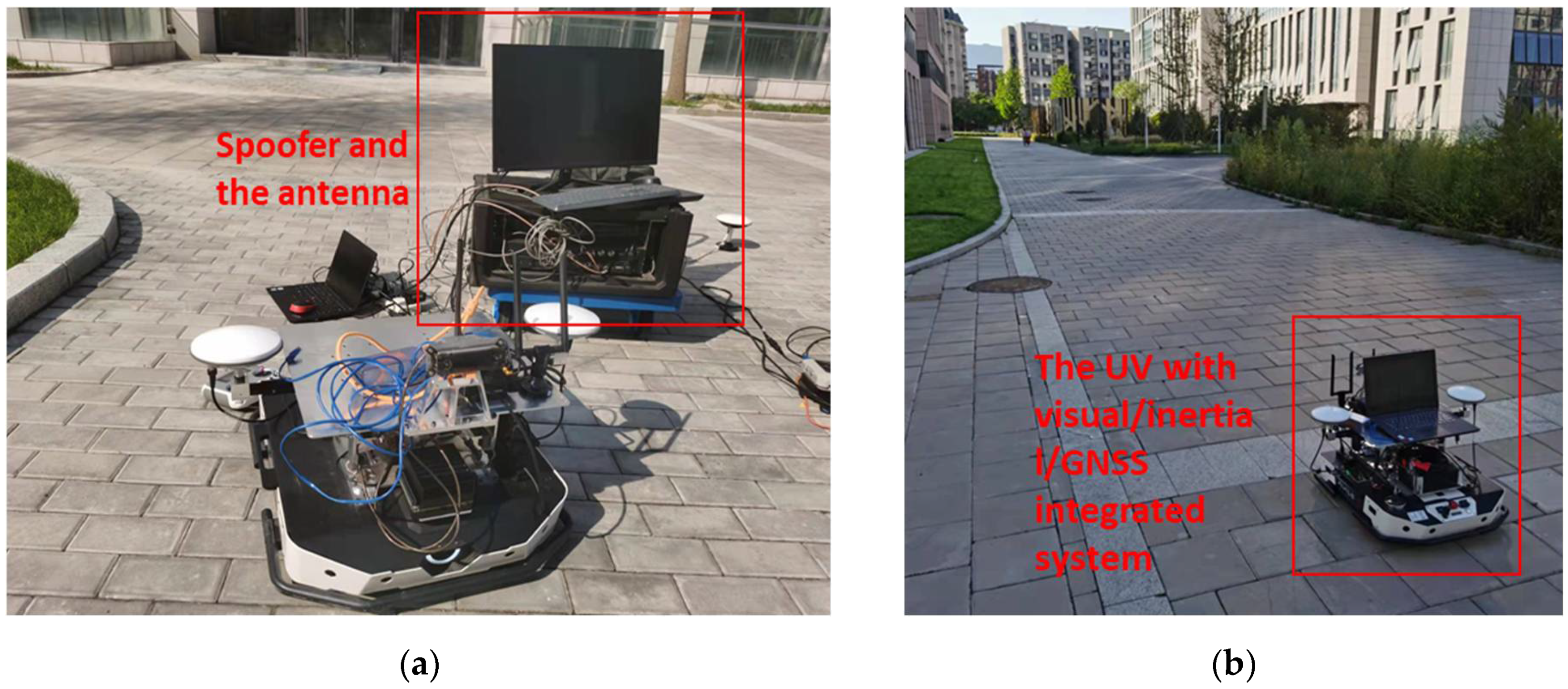
The GNSS spoofing jammer is used to broadcast spoofing signals synchronized with real signals, which is characterized by the ability to simulate the signals of all visible satellites using one device. Each set of signals is clock-synchronized with the real signals of the corresponding satellite. All the spoofing signals point to the preset spoofing position or follow a preset trajectory. The signal-to-noise ratio (SNR) of all spoofing signals is adjusted to be slightly higher than the real satellite signal at the receiver, so that the real signal of the same satellite is covered by spoofing signals. The spoofing signal is synchronized with the real signal so that the characteristics of frequency shift and phase are the same as the real ones. For ordinary commercial receivers, when the spoofing signal appears, the tracking loop of the receiver will naturally switch from locking the real signal to locking the spoofing signal, whose characteristics are exactly the same as the real signal. Based on this spoofing jammer, a spoofing environment is constructed in the experimental site outside of the lab. When the UV runs in the real GNSS environment for a period of time, the spoofing jammer is turned on to test the performance of the integrated navigation and positioning algorithm of the UV in the spoofing environment. Figure 2 shows the GNSS spoofer and the UV platform with a VIG-integrated system.
In the experiment, there are two kinds of control mode for UV: remote control and algorithm automatic control. In the remote-control mode, the output of an integrated positioning system can be recorded in the absence of GNSS spoofing interference and in the presence of GNSS spoofing interference. This is mainly used to analyze the influence of the scale compensation coefficient and optimal pose transformation matrix on positioning results in a spoofing environment. In the second control method, the pose estimation results of the UV are given in real-time by the integrated navigation solution, and the motion states, such as the direction and speed of the UV, are corrected after comparison with the preset path. The automatic control experiment mainly verifies the fully autonomous creation of the global pose map and the fully autonomous navigation and positioning based on the matching of the global pose map under spoofing conditions.
5.2. VIG System Testing in Normal and Spoofing Environment
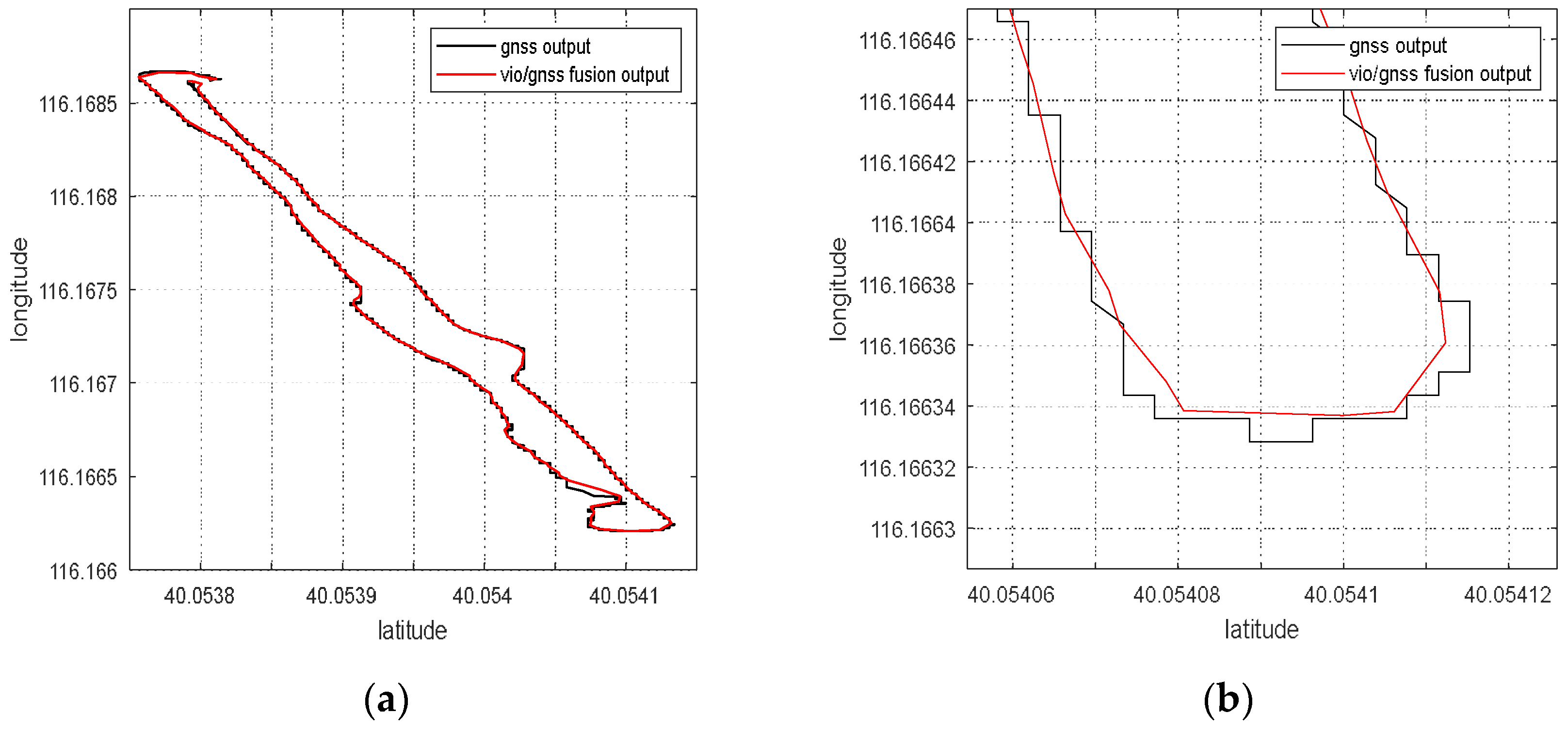
Firstly, the navigation and positioning ability of the VIG system without spoofing signals is verified. The UV is in remote-control mode and moves following the selected path in the experiment area to confirm the normal data transmission of various sensors, such as camera, IMU and GNSS receivers. The global pose output of the integrated system is recorded and compared with the positioning results of the GNSS receiver, as shown in Figure 3.
The black line is the path of GNSS measurements, and the red line is the path of the VIG-integrated results. According to Figure 3, the VIG system can output high-frequency and high-precision positioning solutions when GNSS measurements are normal. Compared with the GNSS measurements with the saltus step, the integrated solution is relatively smoother and more stable.
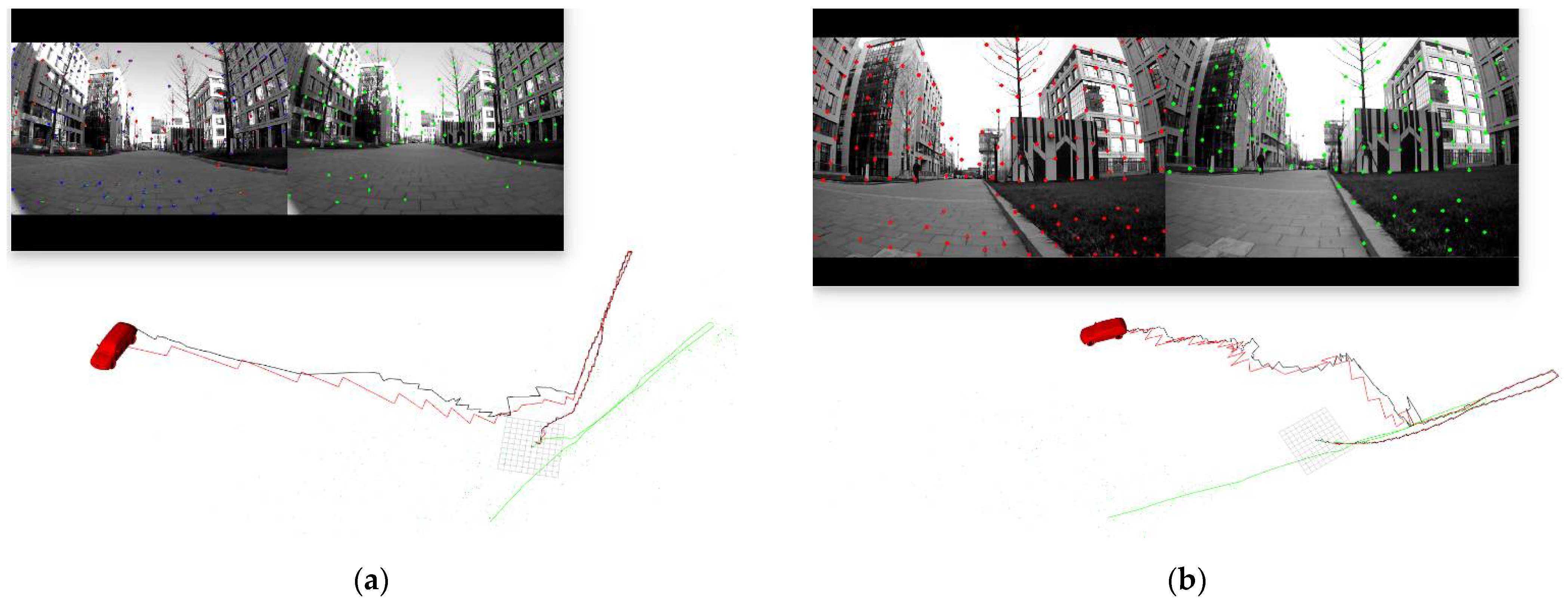
The autonomous navigation and positioning experiment of UV was also carried out. In the experimental site with preset waypoints, the global pose estimation results of the UV are given in real-time by the integrated algorithm. UV moved autonomously according to the pose estimation and the preset waypoints, ensuring that the UV could conduct a real-time positioning solution and maneuver according to the control instructions in real-time. The results of this experiment are shown in Figure 4.
The black line in Figure 4 represents the path of GNSS measurements, and the red line represents the path of VIG-integrated results. The green line in Figure 4a is the path of VIO estimations with no scale compensation and no alignment with ENU coordinate system.
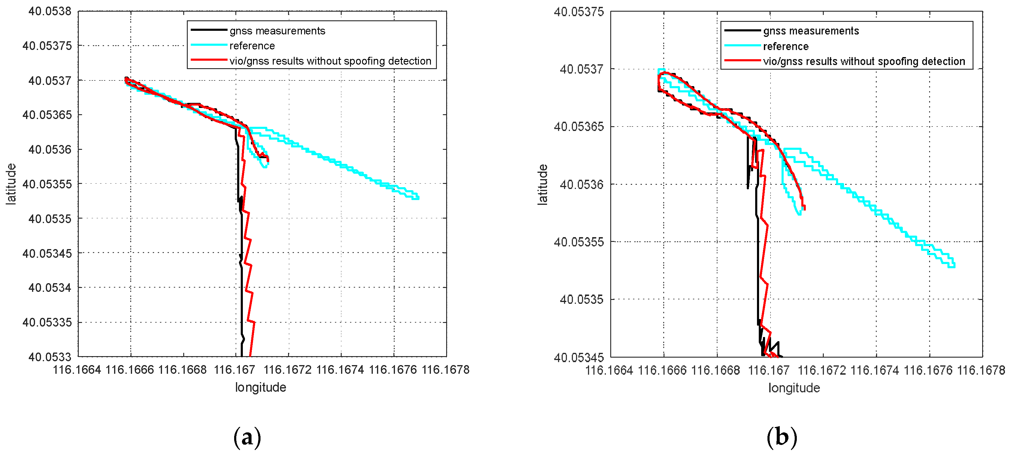
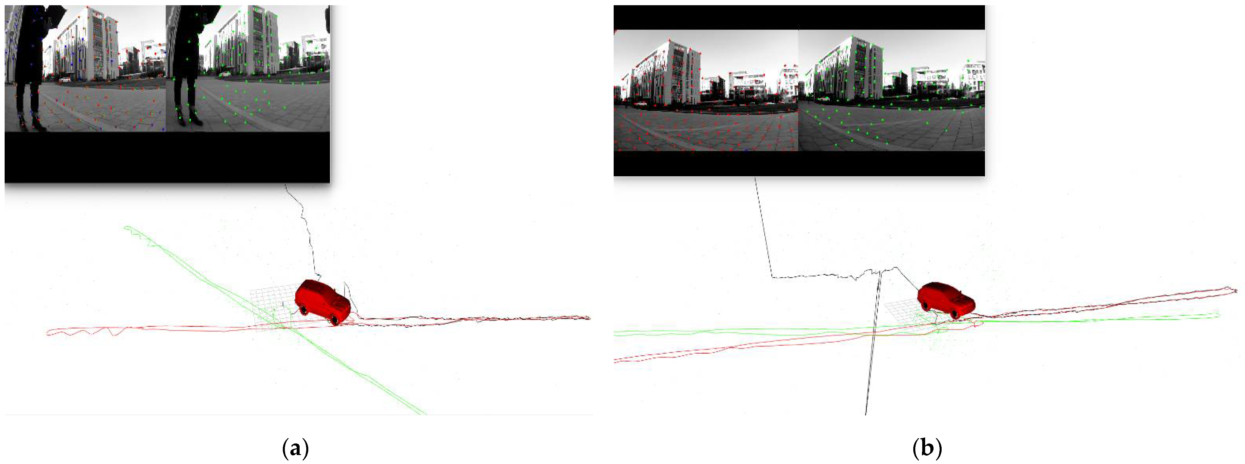
In the following experiment, the GNSS spoofing jammer was used to test the performance of the jammer and the VIG system. The UV was controlled in remote-control mode, and the motion track is the same as that in Figure 4. The UV started moving with no spoofing signals for a moment, and then the GNSS spoofing jammer was turned on. The output of the integrated positioning result was recorded. In this experiment, the spoofing detection module [20] was not enabled, and the algorithm did not judge whether the GNSS measurement is credible. The integrated positioning result is shown in Figure 5 and Figure 6.
The green line in Figure 5 is the path of VIO estimations with no scale compensation and no alignment with ENU coordinate system. The black line is the spoofed GNSS measurements from the GNSS receiver, and the red line is the global positioning results of the integrated positioning system. The reference path is the same as the path in Figure 4b. It can be seen that, when the spoofing detection module is not enabled, the positioning solutions that are output by the integrated system will be induced by spoofing signals. If the system controls the motion state according to the global positioning results, the whole system will be spoofed. In this case, the integrated positioning algorithm of the system provides incorrect global positioning results, which verifies the effectiveness of the GNSS spoofing jammer and illustrates the necessity of a spoofing detection algorithm.
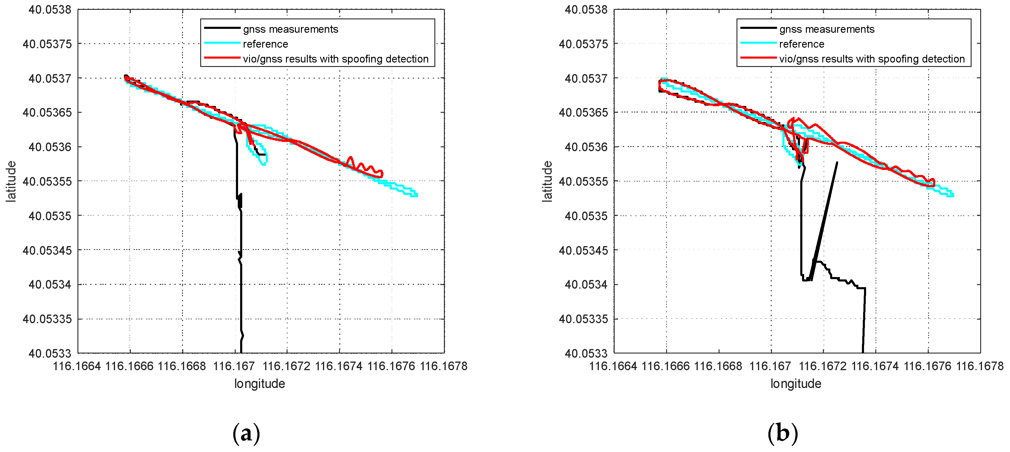
The spoofing detection module in the algorithm comes from previous studies [20]. The same experimental process as above is repeated, then the spoofing detection module is run in the integrated positioning algorithm, and the GNSS spoofing jammer is turned on the process of UV movement. The results of this experiment are shown in Figure 7 and Figure 8.
Compared with Figure 6, the red line in Figure 8 shows that, under the same spoofing conditions, the spoofing detection module detects the existence of spoofing and the integrated positioning results have not been spoofed in this case. In [20], the spoofing detection algorithm is mainly verified through the KITTI [22] dataset. Experimental verification of the spoofing detection algorithm is only carried out in an indoor static state, which is easy to implement. This research contains a further experiment regarding the spoofing detection module of the integrated positioning algorithm in an outfield and a dynamic state. It can be seen from the experimental results in Figure 8 that the VIG system can continue to output global positioning results according to the actual motion track to avoid the system being continuously induced by spoofing signals. However, the comparison between the positioning results and the reference path shows that the integrated positioning system operating in the spoofing environment is affected by the inaccurate estimation of VIO scale.
5.3. The Effects of Scale Estimation Compensation on Global Positioning Results under Spoofing Conditions
Considering that an inaccurate scale derived from VIO initialization will have a serious impact on the global positioning results under the spoofing conditions shown in Figure 8, the scale factor should be estimated and compensated. According to Section 2.2, in the nonlinear optimization of the algorithm, the scale compensation coefficient is optimized and estimated in real-time, and the compensation coefficient of the VIO scale is obtained, along with the global pose. The scale compensation coefficient estimated by optimization in the repeated experiment with the same data as Figure 4 is shown in Figure 9.
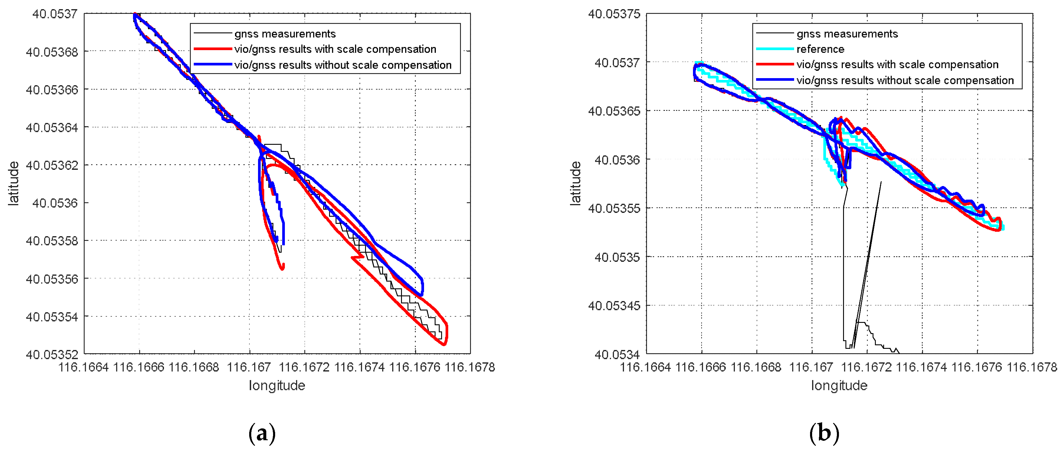
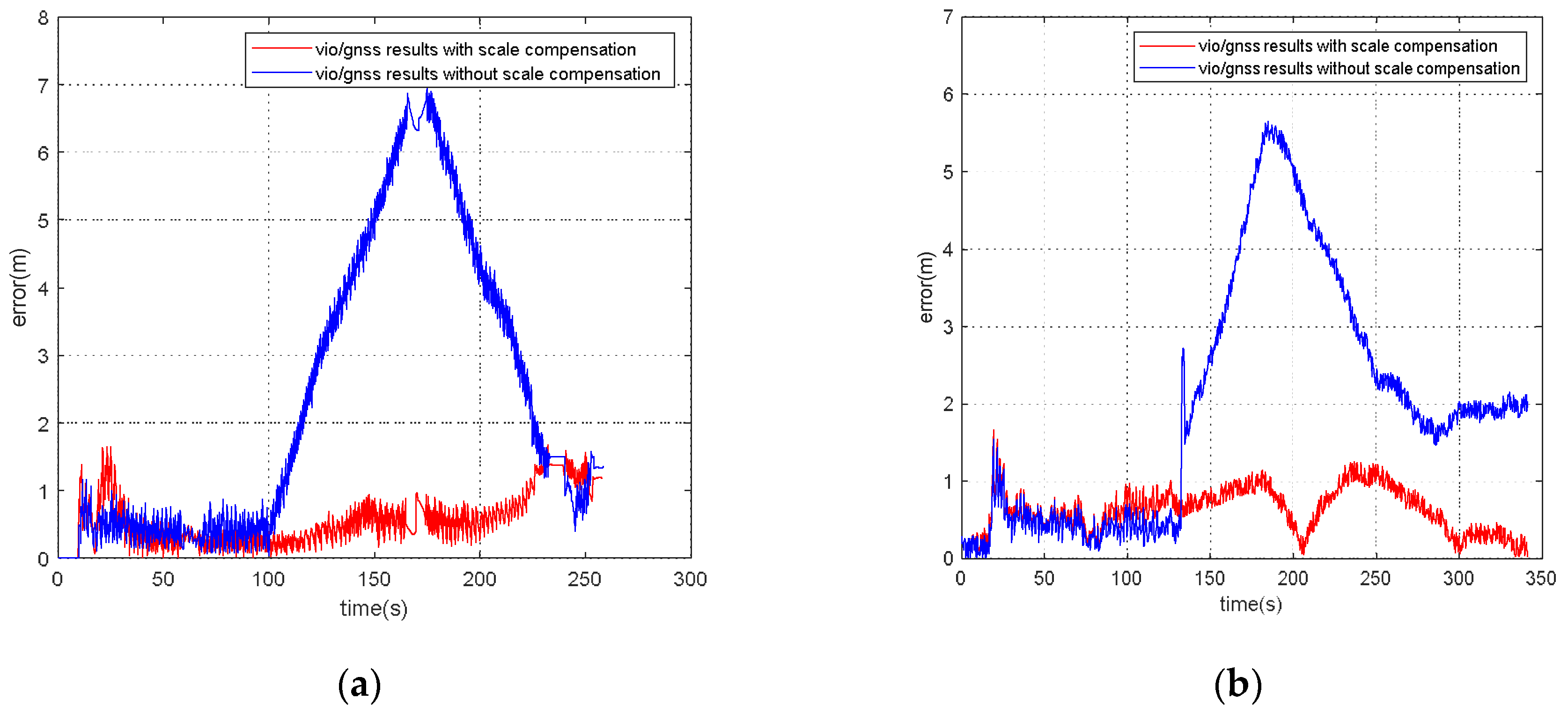
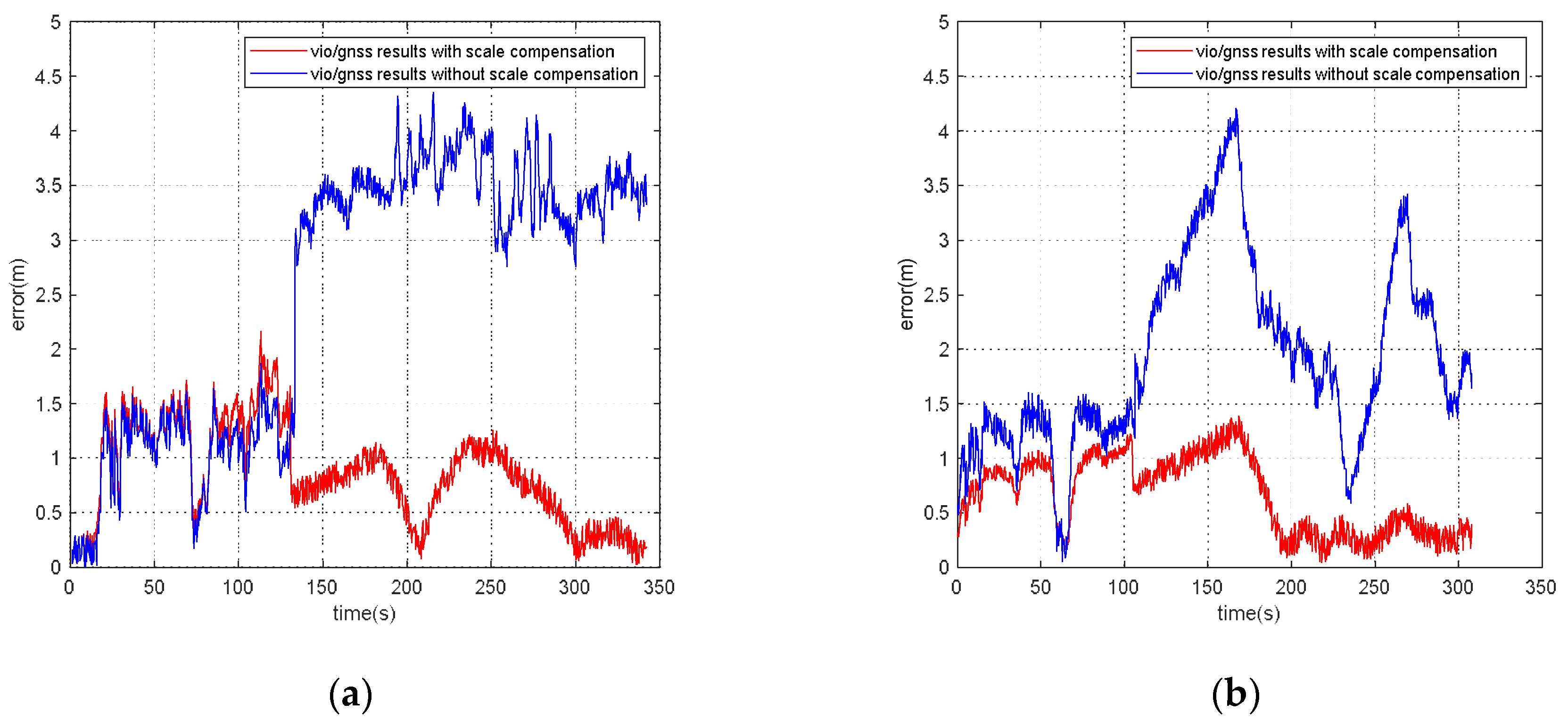
Figure 9a shows that, even for the same set of data, VIO’s scale initialization is unstable, so the scale compensation coefficient is different in each experiment. The scale compensation coefficient is about 1.1, meaning that the relative error of the scale estimate is about 10%, resulting in a relative positioning error about 10% of the positioning results. Figure 9b shows that when there is no spoofing, since the VIG integrated positioning results are continuously corrected by GNSS measurements, the scale problem between the two coordinate systems caused by inaccurate VIO scale estimation has little influence on the global pose estimations, and only affects pose estimation in the time interval between the two optimizations. However, when there are no GNSS measurements or GNSS spoofing interference is detected, the global pose estimations cannot be continuously corrected by GNSS measurements, the global pose estimations highly depend on VIO pose estimation, and an inaccurate VIO scale will greatly affect the accuracy of the global pose estimation, as shown in Figure 10 and Figure 11. Error statistical summary of Figure 11 after GNSS abnormal is shown in Table 1.
Figure 10 shows that the positioning results of the same experimental dataset with and without scale factor compensation are significantly different. In Figure 10a, there are no GNSS measurements in the latter part of the motion. By comparing the blue line with the red line, it can be seen that the maximum positioning error caused by scale can reach 7 m in this case. GNSS spoofing interference exists in the latter part of Figure 10b, which is detected by the integrated navigation and positioning algorithm. Pose estimation is performed independently, without GNSS correction. Figure 11a shows that the errors of the integrated positioning results is restricted when scale factor have been compensated when there is no GNSS correction in the latter half of process. Figure 11b use vio/gnss results when there is no spoofing as a reference. As shown in Table 1, if the scale factor has not been compensated, the maximum errors of these two conditions will up to 6.96 m and 5.67 m, and the mean errors after GNSS abnormal are 3.55 m and 3.05 m. These errors are mostly from the inaccuracy of scale estimation, and will be approximately proportional to the distance UAV traveled. Longer distance the UAV travels from the start point, more obviously the error of scale. After scale compensation, the maximum positioning errors are reduced to 1.68 m and 1.27 m, and the mean errors after GNSS abnormal are reduced to 0.67 m.
5.4. Influence of Optimal Pose Transformation Matrix on Global Positioning Results under Spoofing Conditions
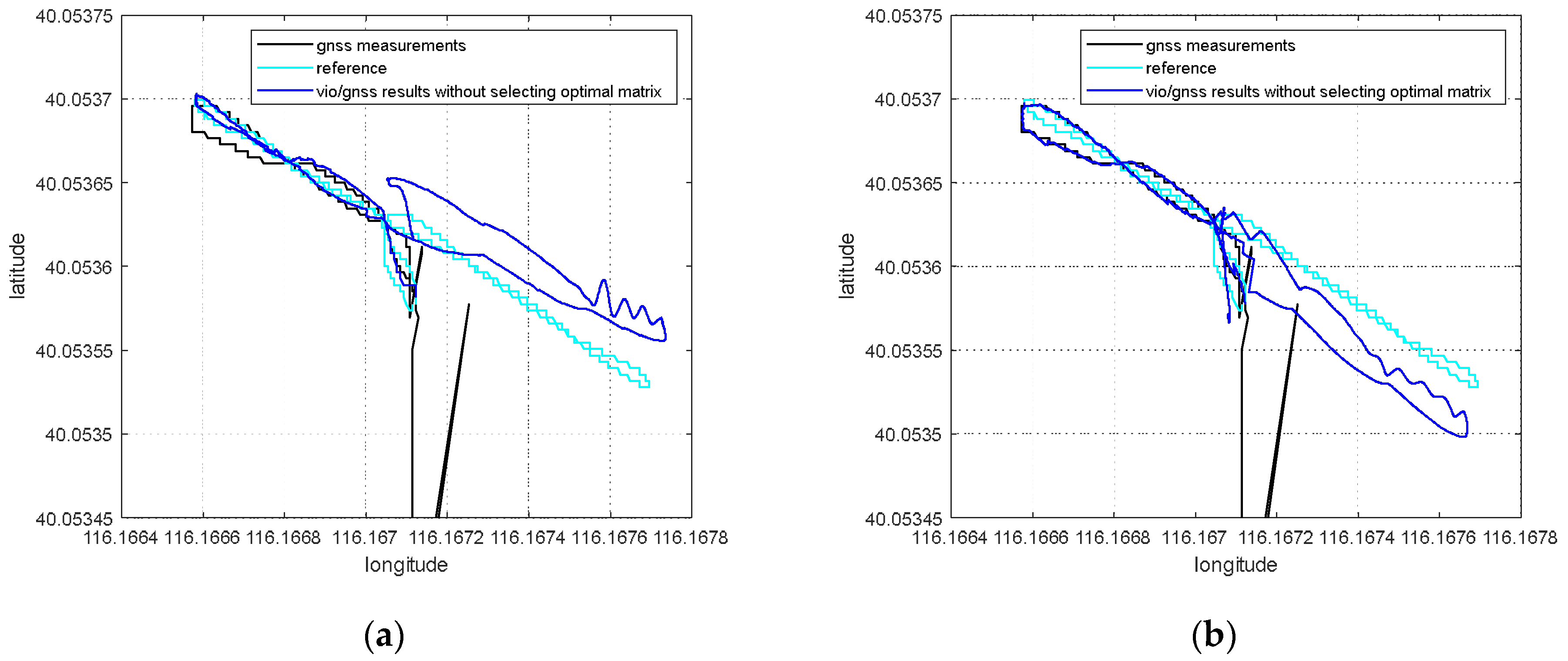
When the VIG system operates in a spoofing environment, it can be seen from Section 4.1 that the transition process of spoofing detection will have an impact on the subsequent integrated positioning results. Although there no real GNSS measurements are used as a reference in the experiment under GNSS spoofing conditions, the experimental track under the real GNSS condition can be used as a reference, because the running tracks of these experiments are similar. The integrated global positioning results achieved without selecting the optimal pose transformation matrix are shown in Figure 12.
The black line in Figure 12 shows the GNSS measurements induced by spoofing interference, the cyan line is the reference trajectory, and the blue line is the pose estimation of the integrated positioning system. Although GNSS spoofing is detected, the positioning result was not completely induced by GNSS spoofing, but the transition process of interference influenced the pose transformation matrix from VIO to the world frame, so that the estimated trajectory has an overall deviation from the reference trajectory and deviates from the real experimental area.
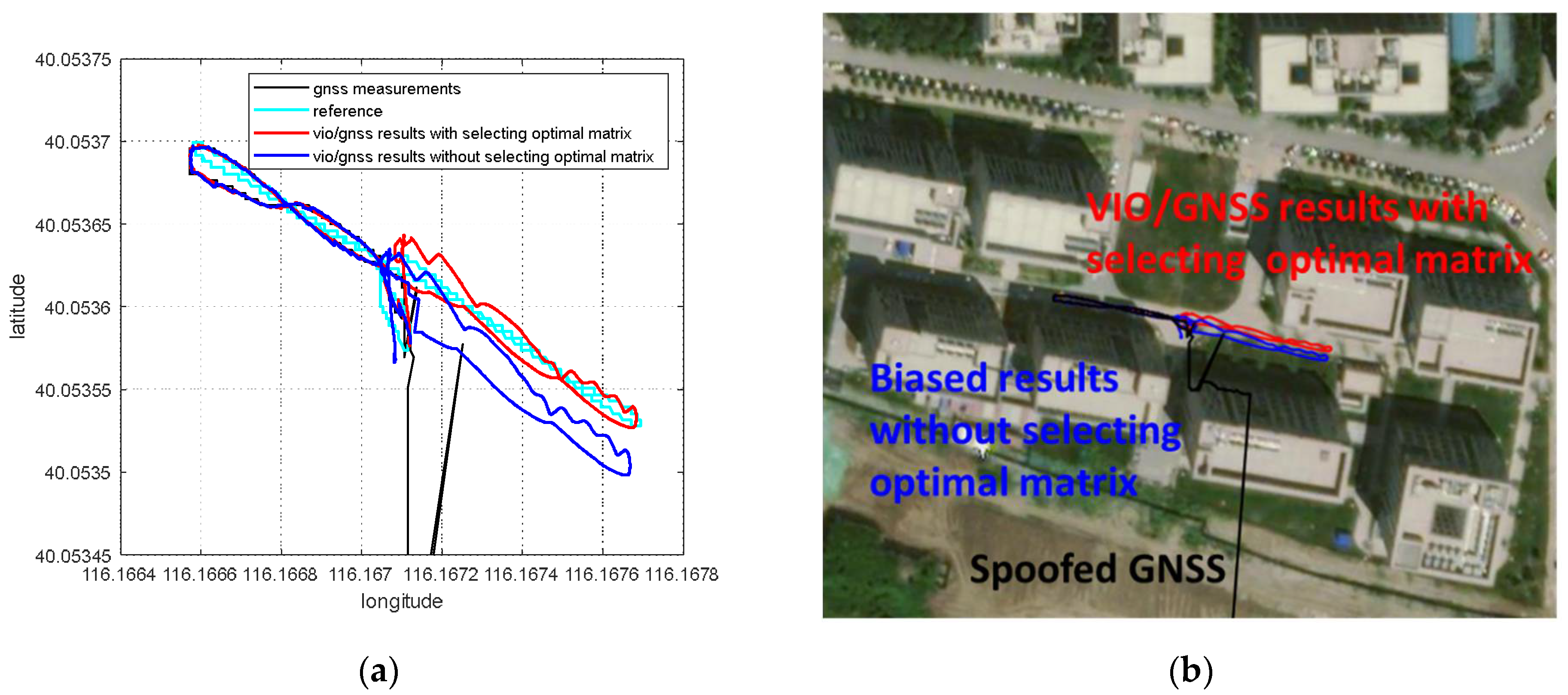
The influence of the transition process of spoofing on the subsequent global positioning result can be eliminated by selecting the optimal pose transformation matrix introduced in Section 4.2. The same set of data in Figure 12 is utilized to estimate the global positioning results, as shown in Figure 13 and Figure 14. Error statistical summary of Figure 14 after GNSS spoofing is shown in Table 2.
The optimal pose transformation matrix was selected according to the principle of the minimum residual of nonlinear optimization. The minimum residual of nonlinear optimization indicates that the pose transformation matrix is not affected by spoofing interference deviations. In Figure 13, the blue line is the positioning result, obtained without selecting the optimal pose transformation matrix, the red line is the result when the optimal matrix is selected. Since there are no real GNSS measurements that can be used as a reference under the condition of spoofing interference, the vio/gnss results when there is no spoofing is using as a reference to analyze the positioning error. Figure 14 shows that the positioning errors after selecting the optimal pose transformation matrix are decreased obviously, compared with the positioning errors that did not select the optimal pose transformation matrix. As shown in Table 2, if the optimal pose transformation matrix has not been selected, the maximum errors of these two spoofing scenarios will up to 4.34 m and 4.23 m, and the mean errors after GNSS spoofing are 3.51 m and 2.35 m. After optimal pose transformation matrix selection, the maximum positioning errors are reduced to 1.25 m and 1.37 m, and the mean errors after GNSS spoofing are reduced to 0.68 m and 0.56 m. In addition to analyzing the positioning error, the results show that the estimated positioning results indicate global deviation when the optimal pose transformation matrix is not selected. The global deviation can be corrected by selecting the optimal pose transformation matrix.
5.5. Navigation and Localization of Revisit Area under GNSS Spoofing Interference
For the VIG system running in the revisit area, the key frame global pose map of this area is first established when there is no spoofing interference according to Section 3.1. The basic parameters of the global pose map are shown in Table 3.
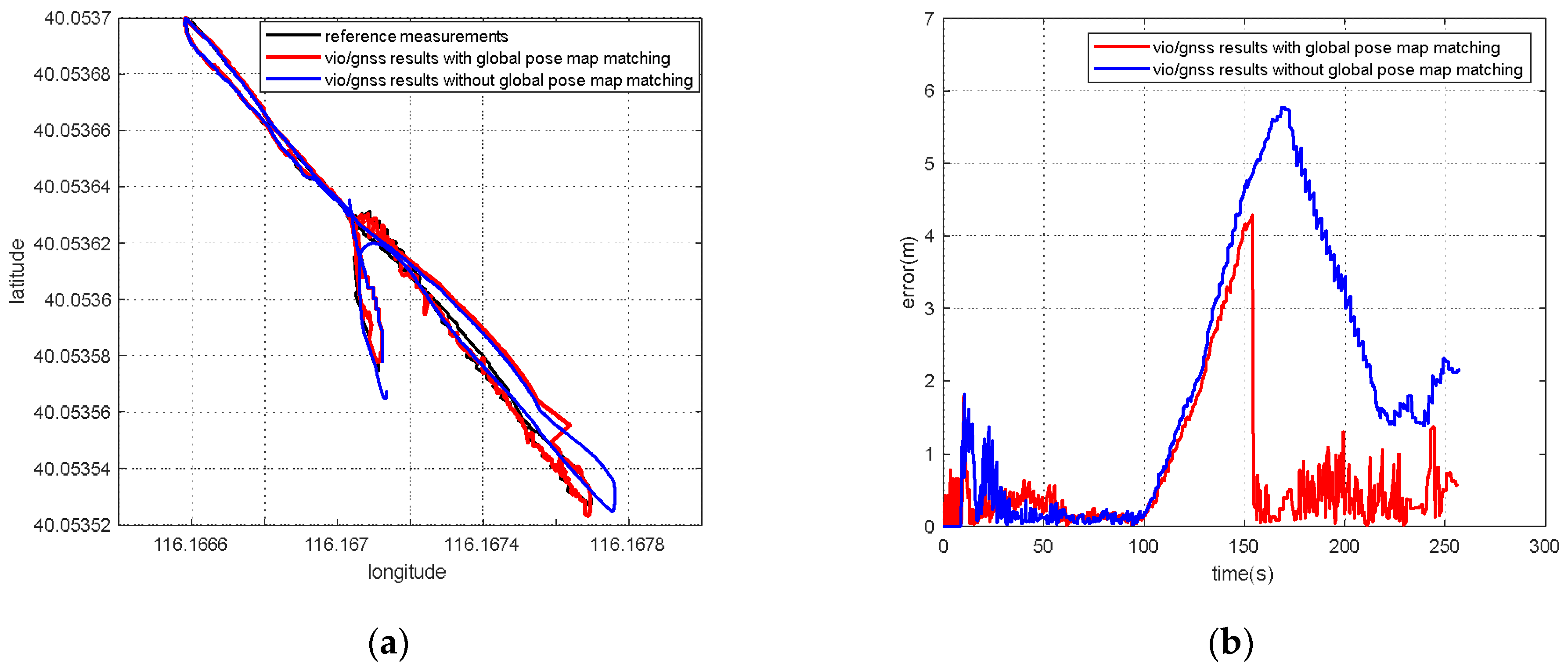
After the keyframe global pose map of the area is established, when UV enters the same area again, the global pose-matching module can be enabled to correct that the absolute pose occurs under GNSS spoofing interference conditions. Firstly, the correction effect of global pose map is verified in the data, showing that there are no GNSS measurements after 100 s of the motion, as shown in Figure 15.
The blue line in Figure 15a shows that the positioning results will deviate from the true value due to inaccurate estimations of scale or for other reasons when there is no GNSS measurments to correct VIO. The jump in the red line shows the correction of the pose estimation after matching with the global pose map. The blue line in Figure 15b shows the positioning error in the case of no correction, and the error in the latter part accumulates with motion. The red line indicates that the positioning error reduced to less than 1 m after matching with the global pose map.
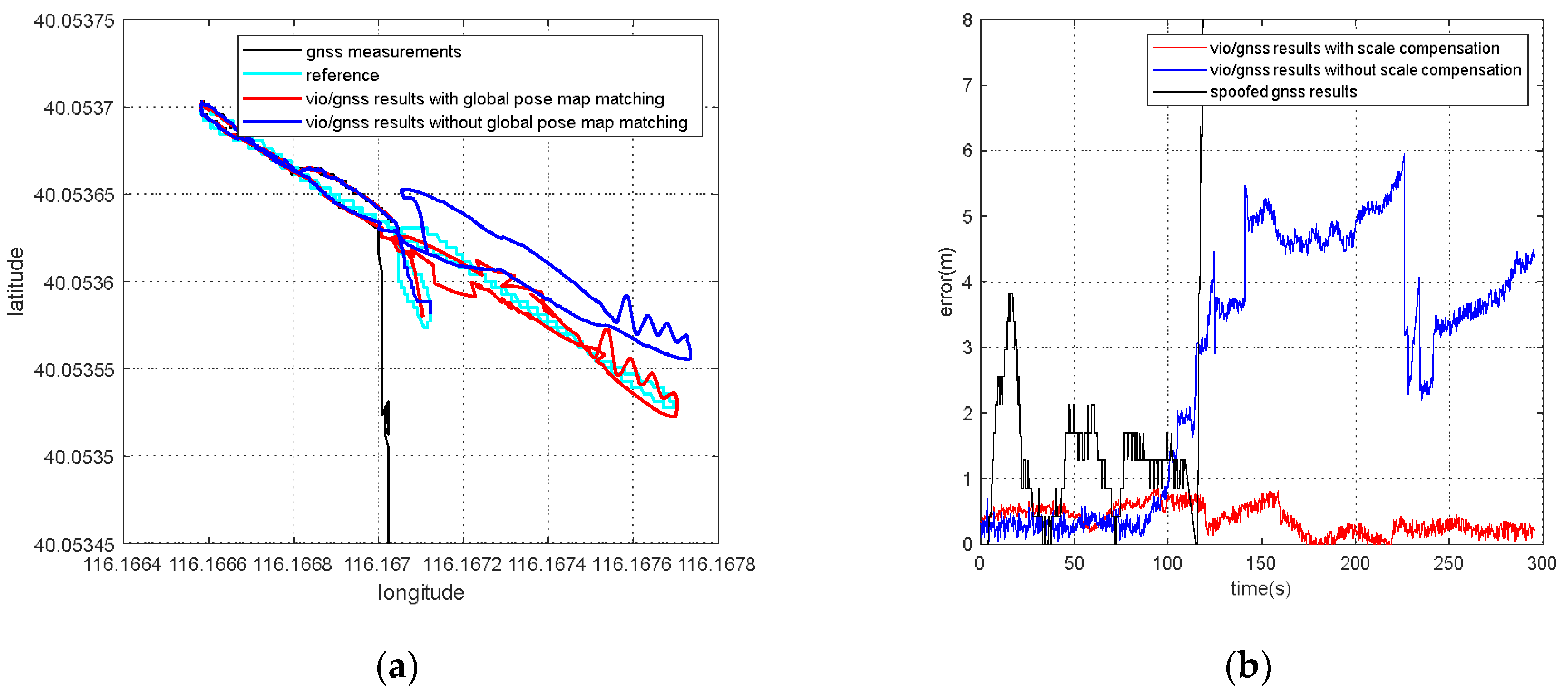
Under the same experimental conditions, the UV was made to run autonomously according to the preset waypoints, and GNSS spoofing jammer was turned on during the movement. When spoofing interference was detected, the global pose map-matching module is started to correct the absolute pose of the system. The positioning result is shown in Figure 16. Error statistical summary of Figure 15b and Figure 16b is shown in Table 4.
Figure 16 shows the positioning results with global pose map-matching when GNSS spoofing interference is detected. The blue line indicates that, under GNSS spoofing interference conditions, the integrated positioning system lacks reliable absolute pose correction information and drifts with no correction. The red line shows the positioning results during global pose map matching, which basically coincide with the preset waypoints. In Figure 16b, the positioning error is analyzed by using vio/gnss results when there is no spoofing as a reference. As shown in Table 4, without the correction of global pose map matching, the maximum errors of these two conditions will up to 5.77 m and 5.97 m, and the mean errors after GNSS abnormal are 2.56 m and 4.21 m. After the correction of global pose map matching, the maximum positioning errors are reduced to 1.37 m and 0.85 m, and the mean errors after GNSS abnormal are reduced to 0.40 m and 0.25 m in a 56.6 m journey. The global pose map matching could provide absolute positioning correction for a large-scale application which beyond the error correction ability of scale compensation method and optimal pose transformation matrix selection method.
6. Discussion
According to the experiment results, when the spoofing detection module proposed in [20] is not enabled, the positioning solutions output by the integrated system will be induced by spoofing signals. This means that the risk of VIG-integrated positioning system in GNSS spoofing scenarios actually exists and requires more attention. The VIO scale estimation error and the transformation matrix deviation in the transition period of spoofing detection proved to be harmful to the global pose estimation of integrated systems under GNSS spoofing. The experiment firstly verifies the effectiveness of the spoofing detection algorithm. Focusing on the problem of inaccurate scale estimation in VIO initialization, a real-time estimation method of scale compensation coefficients for nonlinear optimization framework is proposed in this paper. GNSS measurements are used to estimate the scale compensation coefficients from the VIO local system to the ENU coordinate system. The results of the scale compensation experiment under spoofing show that the relative positioning error of the integrated system can be reduced by an order of magnitude. To eliminate the influence that the spoofing GNSS measurements that enter nonlinear optimization during the spoofing transition process have on the subsequent integrated positioning results, a deviation correction method based on optimal pose transformation matrix selection is proposed in this paper. The experiment results show that the global deviation caused by the influence of the spoofing transition process can be corrected by selecting the optimal pose transformation matrix. For some special areas that the integrated system can revisit many times, a global pose map-matching method is proposed for VIG-integrated algorithms. The experimental results show the effectiveness of the proposed matching method. The relative positioning error of the integrated system and the accumulated error could be reduced by matching the key frames with global pose. The experiment area is limited because of the restrictions of the power of a GNSS spoofer so that it does not influence others. The performance of the integrated system in a large area under spoofing could be further studied.
7. Conclusions
In this paper, the performance of a visual/inertial/GNSS integrated system under GNSS spoofing attack is discussed. The spoofing detection method is based on previous studies [10] and is not the focal point of this study. The focal point is the key problems that mainly affect the positioning accuracy after GNSS spoofing detection. Two of these key problems are discussed: VIO scale estimation errors and errors in the transition period of spoofing detection. Three methods, scale compensation coefficient estimation, optimal pose transformation matrix selection and global pose map-matching, were proposed in this paper to depress the positioning errors due to GNSS spoofing attacks.
For the first time, the VIG-integrated system is evaluated in a real-world GNSS spoofing scenario. The three methods proposed in this paper are tested and compared in spoofing scenarios. All three methods proved that this could be used to improve the performance of the VIG-integrated system operating in a GNSS spoofing environments or under GNSS spoofing threats. Based on this work, the robustness and reliability of the integrated system under GNSS spoofing will be further discussed, and further research will be carried out concerning more complex spoofing scenarios such as intelligence-induced spoofing.
Author Contributions
Conceptualization, Z.Y. and F.X.; software, N.G.; validation, Z.Y., F.X. and N.G.; formal analysis, F.X.; investigation, N.G.; resources, Z.Y.; data curation, N.G.; writing—original draft preparation, N.G.; writing—review and editing, F.X.; visualization, N.G.; supervision, F.X.; project administration, Z.Y. All the authors have read and agreed to the published this version of the manuscript. All authors have read and agreed to the published version of the manuscript.
Funding
This research was carried out in the State Key Laboratory of Precision Measurement Technology and Instruments, Tsinghua University under the financial support by the NSFC project (No. 51827806) and the NSFC project (No. U21A6003).
Data Availability Statement
Not applicable.
Conflicts of Interest
The authors declare no conflict of interest.
References
- Schreiber, M.; Königshof, H.; Hellmund, A.; Stiller, C. Vehicle localization with tightly coupled GNSS and visual odometry. In Proceedings of the 2016 IEEE Intelligent Vehicles Symposium (IV), Gothenburg, Sweden, 19–22 June 2016; pp. 858–863. [Google Scholar]
- Gong, Z.; Ying, R.; Wen, F.; Qian, J.; Liu, P. Tightly Coupled Integration of GNSS and Vision SLAM Using 10-DoF Optimization on Manifold. IEEE Sens. J. 2019, 19, 12105–12117. [Google Scholar] [CrossRef]
- Jafarnia-Jahromi, A.; Broumandan, A.; Nielsen, J.; Lachapelle, G. GPS Vulnerability to Spoofing Threats and a Review of Antispoofing Techniques. Int. J. Navig. Obs. 2012, 2012, 127072. [Google Scholar] [CrossRef] [Green Version]
- Psiaki, M.L.; Humphreys, T.E. GNSS spoofing and detection. Proc. IEEE 2016, 104, 1258–1270. [Google Scholar] [CrossRef]
- Parkinson, S.; Ward, P.; Wilson, K.; Miller, J. Cyber threats facing autonomous and connected vehicles: Future challenges. IEEE Trans. Intell. Transp. Syst. 2017, 18, 2898–2915. [Google Scholar] [CrossRef]
- Shepard, D.; Bhatti, J.; Humphreys, T. Evaluation of smart grid and civilian UAV vulnerability to GPS spoofing attacks. In Proceedings of the ION GNSS Meeting, Nashville, TN, USA, 17–21 September 2012. [Google Scholar]
- Noh, J.; Kwon, Y.; Son, Y.; Shin, H.; Kim, D.; Choi, J.; Kim, Y. Tractor beam: Safe-hijacking of consumer drones with adaptive GPS spoofing. TOPS 2019, 22, 1–26. [Google Scholar] [CrossRef]
- Kerns, A.; Shepard, D.; Bhatti, J.; Humphreys, T. Unmanned Aircraft Capture and Control Via GPS Spoofing. J. Field Robot. 2014, 31, 617–636. [Google Scholar] [CrossRef]
- Groves, P. Principles of GNSS, Inertial, and Multi-Sensor Integrated Navigation Systems; Artech House: Norwood, MA, USA, 2007. [Google Scholar]
- Aumayer, B. Ultra-tightly Coupled Vision/GNSS for Automotive Applications. Ph.D. Thesis, University of Calgary, Calgary, Canada, 2016. [Google Scholar]
- Qin, T.; Pan, J.; Cao, S.; Shen, S. A General Optimization-based Framework for Local Odometry Estimation with Multiple Sensors. arXiv 2019, arXiv:1901.03638. [Google Scholar]
- Cao, S.; Lu, X.; Shen, S. GVINS: Tightly Coupled GNSS-Visual-Inertial Fusion for Smooth and Consistent State Estimation. arXiv 2021, arXiv:2103.07899. [Google Scholar] [CrossRef]
- Meng, L.; Yang, L.; Yang, W.; Zhang, L. A Survey of GNSS Spoofing and Anti-Spoofing Technology. Remote Sens. 2022, 14, 4826. [Google Scholar] [CrossRef]
- Humphreys, T.E.; Ledvina, B.M.; Psiaki, M.L.; O’Hanlon, B.W.; Kintner, P.M. Assessing the Spoofing Threat: Development of a Portable GPS Civilian Spoofer. In Proceedings of the International Technical Meeting of the Satellite Division of the Institute of Navigation, Savannah, GA, USA, 16–19 September 2008. [Google Scholar]
- Tanil, C.; Khanafseh, S.; Pervan, B. The impact of wind gust on detectability of GPS spoofing attack using RAIM with INS coupling. In Proceedings of the ION 2015 Pacific PNT Meeting, Honolulu, HI, USA, 20–23 April 2015; pp. 674–686. [Google Scholar]
- Tanil, C.; Khanafseh, S.; Pervan, B. Detecting global navigation satellite system spoofing using inertial sensing of aircraft disturbance. J. Guid. Control. Dyn. 2017, 40, 2006–2016. [Google Scholar] [CrossRef]
- Yimin, W.; Hong, L.; Mingquan, L. Spoofing profile estimation-based GNSS spoofing identification method for tightly coupled. MEMS INS/GNSS integrated navigation system. IET Radar Sonar Navig. 2019, 14, 216–225. [Google Scholar] [CrossRef]
- Broumandan, A.; Lachapelle, G. Spoofing Detection Using GNSS/INS/Odometer Coupling for Vehicular Navigation. Sensors 2018, 18, 1305. [Google Scholar] [CrossRef] [PubMed] [Green Version]
- Qiao, Y.R.; Zhang, Y.X.; Du, X. A Vision-Based GPS-Spoofing Detection Method for Small UAVs. In Proceedings of the 13th International Conference on Computational Intelligence and Security (CIS), Hong Kong, China, 15–17 December 2017; pp. 312–316. [Google Scholar]
- Gu, N.; Xing, F.; You, Z. GNSS Spoofing Detection Based on Coupled Visual/Inertial/GNSS Navigation System. Sensors 2021, 21, 6769. [Google Scholar] [CrossRef] [PubMed]
- Song, J.; Wu, H.; Guo, X.C.; Jiang, D.; Guo, X.Q.; Lv, T.; Luo, H. GNSS Spoofing Identification and Smoothing Localization Method for GNSS/Visual SLAM System. Appl. Sci. 2022, 12, 1386. [Google Scholar] [CrossRef]
- Geiger, A.; Lenz, P.; Urtasun, R. Are we ready for autonomous driving? The kitti vision benchmark suite. In Proceedings of the IEEE International Conference on Pattern Recognition, Tsukuba, Japan, 11–15 November 2012; pp. 3354–3361. [Google Scholar]
- Hong, E.; Lim, J. Visual-Inertial Odometry with Robust Initialization and Online Scale Estimation. Sensors 2018, 18, 4287. [Google Scholar] [CrossRef] [Green Version]
- Surber, J.; Teixeira, L.; Chli, M. Robust Visual-Inertial Localization with Weak GPS Priors for Repetitive UAV Flights. In Proceedings of the IEEE International Conference on Robotics and Automation (ICRA), Singapore, 29 May–3 June 2017; pp. 6300–6306. [Google Scholar]
- Oleynikova, H.; Burri, M.; Lynen, S.; Siegwart, R. Real-time visual-inertial localization for aerial and ground robots. In Proceedings of the IEEE/RSJ International Conference on Intelligent Robots and Systems (IROS), Macau, China, 4–8 November 2015; pp. 3079–3085. [Google Scholar]
- Qin, T.; Li, P.; Shen, S. VINS-Mono: A Robust and Versatile Monocular Visual-Inertial State Estimator. IEEE Trans. Robot. 2018, 34, 1004–1020. [Google Scholar] [CrossRef] [Green Version]
- Campos, C.; Elvira, R.; Rodríguez, J.J.G.; Montiel, J.M.M.; Tardós, J.D. ORB-SLAM3: An Accurate Open-Source Library for Visual, Visual–Inertial, and Multimap SLAM. IEEE Trans. Robot. 2021, 37, 1874–1890. [Google Scholar] [CrossRef]
- Mur-Artal, R.; Montiel, J.M.M.; Tardós, J.D. ORB-SLAM: A Versatile and Accurate Monocular SLAM System. IEEE Trans. Robot. 2015, 31, 1147–1163. [Google Scholar] [CrossRef] [Green Version]
- Mur-Artal, R.; Tardós, J.D. Orb-slam2: An open-source slam system for monocular, stereo, and rgb-d cameras. IEEE Trans. Robot. 2017, 33, 1255–1262. [Google Scholar] [CrossRef] [Green Version]
- Dai, B.; He, Y.; Yang, L.; Su, Y.; Yue, Y.; Xu, W. SIMSF: A Scale Insensitive Multi-Sensor Fusion Framework for Unmanned Aerial Vehicles Based on Graph Optimization. IEEE Access 2020, 8, 118273–118284. [Google Scholar] [CrossRef]
- Agarwal, S.; Mierle, K.; The Ceres Solver Team. Ceres Solver. Available online: http://ceres-solver.org (accessed on 20 November 2022).
- Galvez-López, D.; Tardos, J.D. Bags of Binary Words for Fast Place Recognition in Image Sequences. IEEE Trans. Robot. 2012, 28, 1188–1197. [Google Scholar] [CrossRef]
- Rosten, E.; Drummond, T. Machine learning for high-speed corner detection. In Proceedings of the European Conference on Computer Vision, Graz, Austria, 7–13 May 2006; Volume 1, pp. 430–443. [Google Scholar]
- Calonder, M.; Lepetit, V.; Strecha, C.; Fua, P. BRIEF: Binary Robust Independent Elementary Features. In Proceedings of the European Conference on Computer Vision, Crete, Greece, 5–11 September 2010; Volume 6314, pp. 778–792. [Google Scholar]
- Arthur, D.; Vassilvitskii, S. K-means++: The advantages of careful seeding. In Proceedings of the ACM-SIAM Symposium on Discrete Algorithms, New Orleans, LA, USA, 7–9 January 2007; pp. 1027–1035. [Google Scholar]
Figure 1.
An illustration of the proposed algorithm and the visual/inertial/GNSS integrated navigation system.
Figure 1.
An illustration of the proposed algorithm and the visual/inertial/GNSS integrated navigation system.

Figure 2.
(a) GNSS spoofer used in the experiment; (b) the integrated positioning system with cameras, an IMU, and a GNSS receiver in the experiment UV platform.
Figure 2.
(a) GNSS spoofer used in the experiment; (b) the integrated positioning system with cameras, an IMU, and a GNSS receiver in the experiment UV platform.

Figure 3.
The output of VIG-integrated algorithm and the positioning result of GNSS receiver: (a) The positioning results of the UV with VIG fusion output in red and GNSS output in black; (b) the part of another path of UV.
Figure 3.
The output of VIG-integrated algorithm and the positioning result of GNSS receiver: (a) The positioning results of the UV with VIG fusion output in red and GNSS output in black; (b) the part of another path of UV.

Figure 4.
The autonomous navigation and positioning experiment: (a) the estimation of the UV motion path; (b) the motion path in google map.
Figure 4.
The autonomous navigation and positioning experiment: (a) the estimation of the UV motion path; (b) the motion path in google map.

Figure 5.
The pose estimation of the UV (red) without spoofing detection compared with the GNSS measurements (black) (a) in scenario 1; (b) in scenario 2.
Figure 5.
The pose estimation of the UV (red) without spoofing detection compared with the GNSS measurements (black) (a) in scenario 1; (b) in scenario 2.

Figure 6.
The comparison of the integrated positioning results (red) without spoofing detection and the GNSS measurements (black) (a) in scenario 1; (b) in scenario 2.
Figure 6.
The comparison of the integrated positioning results (red) without spoofing detection and the GNSS measurements (black) (a) in scenario 1; (b) in scenario 2.

Figure 7.
The output of the integrated positioning system (red) with spoofing detection compared with the GNSS measurements (black) (a) in scenario 1; (b) in scenario 2.
Figure 7.
The output of the integrated positioning system (red) with spoofing detection compared with the GNSS measurements (black) (a) in scenario 1; (b) in scenario 2.

Figure 8.
The comparison of the integrated positioning results (blue) with spoofing detection and the GNSS measurements (black) (a) in scenario 1; (b) in scenario 2.
Figure 8.
The comparison of the integrated positioning results (blue) with spoofing detection and the GNSS measurements (black) (a) in scenario 1; (b) in scenario 2.

Figure 9.
(a) The scale compensation coefficient estimated by optimization in the repeated experiment of the same data; (b) the positioning results with scale compensation compared with the positioning results without the scale compensation with no spoofing interference.
Figure 9.
(a) The scale compensation coefficient estimated by optimization in the repeated experiment of the same data; (b) the positioning results with scale compensation compared with the positioning results without the scale compensation with no spoofing interference.

Figure 10.
(a) The comparison of the global positioning results without GNSS correction in the latter half of the process, with scale factor compensation and without compensation; (b) the comparison of global positioning results with scale factor compensation and without compensation under GNSS spoofing.

Figure 11.
(a) The error analysis with and without scale factor compensation when there is no GNSS correction in the latter half of process; (b) the error analysis with and without scale factor compensation under GNSS spoofing using vio/gnss results when there is no spoofing as a reference.
Figure 11.
(a) The error analysis with and without scale factor compensation when there is no GNSS correction in the latter half of process; (b) the error analysis with and without scale factor compensation under GNSS spoofing using vio/gnss results when there is no spoofing as a reference.

Figure 12.
The overall migration of the integrated global positioning results without selecting the optimal pose transformation matrix: (a) spoofing scenario 1; (b) spoofing scenario 2.
Figure 12.
The overall migration of the integrated global positioning results without selecting the optimal pose transformation matrix: (a) spoofing scenario 1; (b) spoofing scenario 2.

Figure 13.
The integrated global positioning results with selecting the optimal pose transformation matrix: (a) the estimation of the global results; (b) the motion path in google map.
Figure 13.
The integrated global positioning results with selecting the optimal pose transformation matrix: (a) the estimation of the global results; (b) the motion path in google map.

Figure 14.
The error comparison with and without selecting the optimal pose transformation matrix: (a) Spoofing scenario 1; (b) Spoofing scenario 2.
Figure 14.
The error comparison with and without selecting the optimal pose transformation matrix: (a) Spoofing scenario 1; (b) Spoofing scenario 2.

Figure 15.
Verifying the correction effect of global pose map in GNSS-denied environment: (a) the global positioning results; (b) the errors in the results.
Figure 15.
Verifying the correction effect of global pose map in GNSS-denied environment: (a) the global positioning results; (b) the errors in the results.

Figure 16.
(a)The integrated global positioning results comparison with and without keyframe global pose map-matching in spoofing environment; (b)the error analysis of positioning results with and without keyframe global pose map-matching.
Figure 16.
(a)The integrated global positioning results comparison with and without keyframe global pose map-matching in spoofing environment; (b)the error analysis of positioning results with and without keyframe global pose map-matching.


Table 1.
Error statistical summary of Figure 11 after GNSS abnormal.
Table 1.
Error statistical summary of Figure 11 after GNSS abnormal.
| (a) No GNSS Correction (m) | (b) under GNSS Spoofing (m) | |||||
|---|---|---|---|---|---|---|
| Maximum Error | Mean Error | Standard Deviation | Maximum Error | Mean Error | Standard Deviation | |
| With scale compensation | 1.68 | 0.67 | 0.37 | 1.27 | 0.67 | 0.32 |
| Without scale compensation | 6.96 | 3.55 | 1.92 | 5.67 | 3.05 | 1.27 |
Table 2.
Error statistical summary of Figure 14 after GNSS spoofing.
Table 2.
Error statistical summary of Figure 14 after GNSS spoofing.
| (a) Spoofing Scenario 1 (m) | (b) Spoofing Scenario 2 (m) | |||||
|---|---|---|---|---|---|---|
| Maximum Error | Mean Error | Standard Deviation | Maximum Error | Mean Error | Standard Deviation | |
| With selecting optimal matrix | 1.25 | 0.68 | 0.32 | 1.37 | 0.56 | 0.37 |
| Without selecting optimal matrix | 4.34 | 3.51 | 0.35 | 4.23 | 2.35 | 0.80 |
Table 3.
Basic parameters of the global pose map.
| The Scope of the Area | The Number of Key Frames | The Number of Feature Points |
|---|---|---|
| About 10 m × 100 m | 157 | 3112 |
Publisher’s Note: MDPI stays neutral with regard to jurisdictional claims in published maps and institutional affiliations. |
© 2022 by the authors. Licensee MDPI, Basel, Switzerland. This article is an open access article distributed under the terms and conditions of the Creative Commons Attribution (CC BY) license (https://creativecommons.org/licenses/by/4.0/).
Share and Cite
MDPI and ACS Style
Gu, N.; Xing, F.; You, Z. Visual/Inertial/GNSS Integrated Navigation System under GNSS Spoofing Attack. Remote Sens. 2022, 14, 5975. https://doi.org/10.3390/rs14235975
AMA Style
Gu N, Xing F, You Z. Visual/Inertial/GNSS Integrated Navigation System under GNSS Spoofing Attack. Remote Sensing. 2022; 14(23):5975. https://doi.org/10.3390/rs14235975
Chicago/Turabian StyleGu, Nianzu, Fei Xing, and Zheng You. 2022. "Visual/Inertial/GNSS Integrated Navigation System under GNSS Spoofing Attack" Remote Sensing 14, no. 23: 5975. https://doi.org/10.3390/rs14235975
Note that from the first issue of 2016, this journal uses article numbers instead of page numbers. See further details here.