Wearable Hearing Assist System to Provide Hearing-Dog Functionality †

College of Industrial Technology, Nihon University, 1-2-1 Izumi-Cho, Narashino 275-8575, Japan
†
This paper is an extended version of Shimoyama, R.; Syou, I. Wearable Hearing Support System Tapping toward Sound Source. In Proceedings of the 26 International Conference on Robotics in Alpes-Adria-Danube Region (RAAD), Torino, Italy, 21–23 June 2017.
Robotics 2019, 8(3), 49; https://doi.org/10.3390/robotics8030049
Submission received: 10 May 2019
/
Revised: 21 June 2019
/
Accepted: 24 June 2019
/
Published: 26 June 2019
Abstract
:This study developed a wearable hearing-assist system that can identify the direction of a sound source while using short-term interaural time differences (ITDs) of sound pressure and convey the sound source direction to a hearing-impaired person via vibrators that are attached to his or her shoulders. This system, which is equipped with two microphones, could dynamically detect and convey the direction of front, side, and even rear sound sources. A male subject was able to turn his head toward continuous or intermittent sound sources within approximately 2.8 s when wearing the developed system. The sound source direction is probably overestimated when the interval between the two ears is smaller. When the subject can utilize vision, this may help in tracking the location of the target sound source, especially if the target comes into view, and it may shorten the tracking period.
1. Introduction
Most of the animals can localize the source of a sound, typically to run away from predators or capture prey. They instinctively turn their head to estimate the position of the sound source. It is thought that the sound source direction can be most accurately estimated when their head is facing the source. We often turn our face toward the sound of a car when we cross the road. However, a hearing-impaired person hardly notices objects that are approaching from the side or rear because they cannot hear the surrounding sounds that are from sources out of their field of vision. Thus, the hearing-impaired person has a high risk of collisions with cars and motorcycles outdoors.
Several conditions, such as ages, illness, and genetics, may play a role in hearing loss. Noise at work places or listening loud music by earphones may continuously damage our ears. Hearing loss is classified into four categories: Mild, Moderate, Severe, and Profound hearing losses [1]. Hearing aids, bone conductive earphones, and inner ear implants are conventionally used by hearing-impaired persons. These tools are utilized for assisting their diminished, but present, hearing functions, but they are not accessible to the deaf, who have completely lost hearing function. We addressed the deaf and profound hearing loss people who cannot hear when other people are speaking unless they are extremely loud. Young people who walk listening to music loudly by earphones cannot hear surrounding sounds. They can be categorized as profound loss. A hearing-impaired person could have improved quality of life if a wearable hearing-assist system that detects sounds with microphones, localizes the sound source, and notifies the wearer of the source direction could be developed. Such functionality is similar to that of a hearing dog, which is trained to alert hearing-impaired persons of sounds, such as the ringing of alarms or telephones. Several studies on hearing-dog robots have been reported [2,3]. These robots are intended to be analogous to hearing dogs by detecting sounds, localizing their source, recognizing the sound quality, classifying the source, and alerting the hearing-impaired-person. These robots have to locate the person whenever any notification is needed since a stand-alone robot does not always stay beside the person [2]. Thus, we developed a wearable robot system that is always with the person wherever they are, even outdoors. Several fundamental ideas and techniques that are related to the present system are discussed below.
Two ear microphones were adapted for detecting sounds in our wearable system, since ear microphones are easy to wear and stay in place, when compared with multi-microphone arrays. Many studies reported sound source localization while using binaural microphones [4,5]. Most of them dealt with frontal sound sources but not with rear sources. We need to not deal with only frontal, but also rear sound sources, since cars can come from any direction. Thus, we faced some difficulties, such as the “cone of confusion”, for sound source localization [6,7]. How humans localize sound sources provided some direction on how to handle this. Humans localize sound sources while using the interaural time difference (ITD) and interaural intensity difference (IID) of sound pressure at both ears [8,9]. Wallach suggested that sound radiated from every sound source located on a geometrical cone shape had the same ITD and IID values [10]. He further discussed how humans solve ambiguous source positions. Several horizontal directions to the same source are obtained if the head rotates during a continuous sound, and humans can resolve ambiguous source positions. Many experiments supported this principle. Thus, head rotation may assist in the localization of ambiguous sound source positions, although head rotation is not the only way to solve such ambiguity [11,12,13,14,15]. His principle rested on several assumptions. For example, the effectiveness of head rotation depends on sound duration. For long durations, head rotation is effective, but its effectiveness is limited for short sound durations. An additional assumption was that the sound source does not move while the head is rotating.
It is first necessary to resolve ambiguous source positions in a binaural machine system that mimics human binaural hearing. Ambiguous source positions can be resolved while using a system with a set of dynamic microphones, where the microphones change their direction while keeping the same distance [16,17,18,19,20]. Bustamante et al. proposed a three-stage framework to active source localization [20]. They suggested theoretical bases for solving the “Cone of confusion” by the movement of two microphones and briefly reported several successful experiments in the anechoic room. They adapted the short-term detection and analysis of binaural stream. It is known that the reverberation causes temporal fluctuations in short-term interaural phase differences (IPDs) and interaural level differences (ILDs) [21,22]. The statistical properties of the received sound signals have been processed in the sound source localization in room acoustics [22,23,24,25,26,27]. The accuracy of measurement decreased in a shorter time frame. Reverberation degrades the repeatability of measurement due to the temporal fluctuations in short-term IPDs and ILDs, although a shorter time frame is valid for conducting temporal measurement [24]. Author has proposed bio-inspired algorithms on sound source localization that is similar to the auditory mechanism of a Barn Owl [28,29]. Neural based algorithms have been widely known in signal processing community [30,31,32,33]. We adapted one of the neural base algorithms on sound source localization, which is simple and robust in reverberating conditions.
Baumann et al. proposed a mathematical model for identifying horizontal source direction while using ITD variation when a binaural system rotates [34]. They also presented a simple and effective mathematical model for localizing a two-dimensional (2D) sound source. The microphone rotation depends on the sign of the ITDs in their model. The system continues to rotate until the vertical plane of the microphones faces the sound source. They indicated that the system becomes unstable as the ITD approaches zero. Their model had no experimental evidences. We adapted Baumann’s simple model to our wearable hearing-assist system for notifying the subject which hemisphere has the sound source. The system continues to identify the hemisphere containing the source to the subject until the subject faces the sound source. Consequently, the system can resolve ambiguous source positions and also probably track the moving sound sources.
An effective method for notifying the subject which hemisphere contains the sound source is necessary in developing the hearing assist system. Display on a screen is often an easy and useful way to convey information. However, visual display is not suitable as a man-machine interface in this case, because the hearing-impaired person needs their vision to discern the surrounding environment. Thus, we used vibrators for conveying information. Several methods were proposed for motion instruction as a tactile interface [35,36,37,38,39,40,41,42]. Ross et al. proposed an array of 3 × 3 vibrators that were attached to the subject’s back for indicating walking directions by changing the patterns of vibration [35]. However, nine vibrators that were attached to the back were heavy, and not all of them could maintain firm attachment to transmit clear signals. The piezo-electric displays of various specifications have been developed [39]. Khin et al. presented a fabric-based soft tactile actuator [41]. Ontenna is one of the hearing-assist tools for the deaf [42]. Ontenna is a hairpin that translates sound intensity to light and vibration intensity that a deaf person can recognize. In our system, a vibrator that was attached on each shoulder of a vest was utilized to convey information to the subject.
In this study, a new wearable hearing-assist system for the deaf was developed. This paper does not present a new sound source estimator, but it clarifies that the cone of confusion on binaural sound source localization can be dynamically solved, even while using a conventional source estimator for an application system providing hearing-dog functionality. The system identifies the direction of a sound source using short-term ITDs of sound pressure and notifies the subject which hemisphere contains the sound source by the vibration of two vibrators that were attached at the shoulders. An algorithm that was similar to the auditory mechanism of a Barn owl was utilized for identifying the direction of sound source while using short-term ITDs [43,44,45]. This algorithm is redundant and adaptable for real surrounding conditions. We assumed that the subject’s auditory function is impaired, but that his or her visual function is not impaired. Several experiments were performed, including one with the sound source behind the subject, where the subject could not directly confirm the source by vision alone.
In Section 2, the algorithm for identifying ITDs is proposed. The ambiguity of the phase difference of sound pressures and the determination of ITDs are discussed. In Section 3, the proposed algorithm is applied to fundamental movements of a humanoid robot head to simplify the problem, including how the head can turn to identify the front and rear sound sources. The system configuration and the relation between ITDs and sound source direction are described. The effect of various sound qualities and several distances between humanoid robot and loudspeaker are described.
Section 4 presents a wearable hearing assist system for humans. The results of several experiments with a subject wearing the hearing assist system are presented. The effect of interval between the ears on sound source direction is discussed. The effect of vision was evaluated by having the subject wear an eye mask. We also present experimental results comparing system performance with continuous and intermittent sounds. In Section 5, we discuss the conclusions and describe future work.
We have briefly reported a wearable hearing-assist system [46]. This paper is an extended version of the paper which clarifies the reason why could “Cone of confusion” be resolved.
2. Algorithm for Identifying ITDs
In this chapter, we briefly refer one of neural base algorithms on sound source localization [31,32].
2.1. Ambiguity of Phase Difference of Sound Pressure
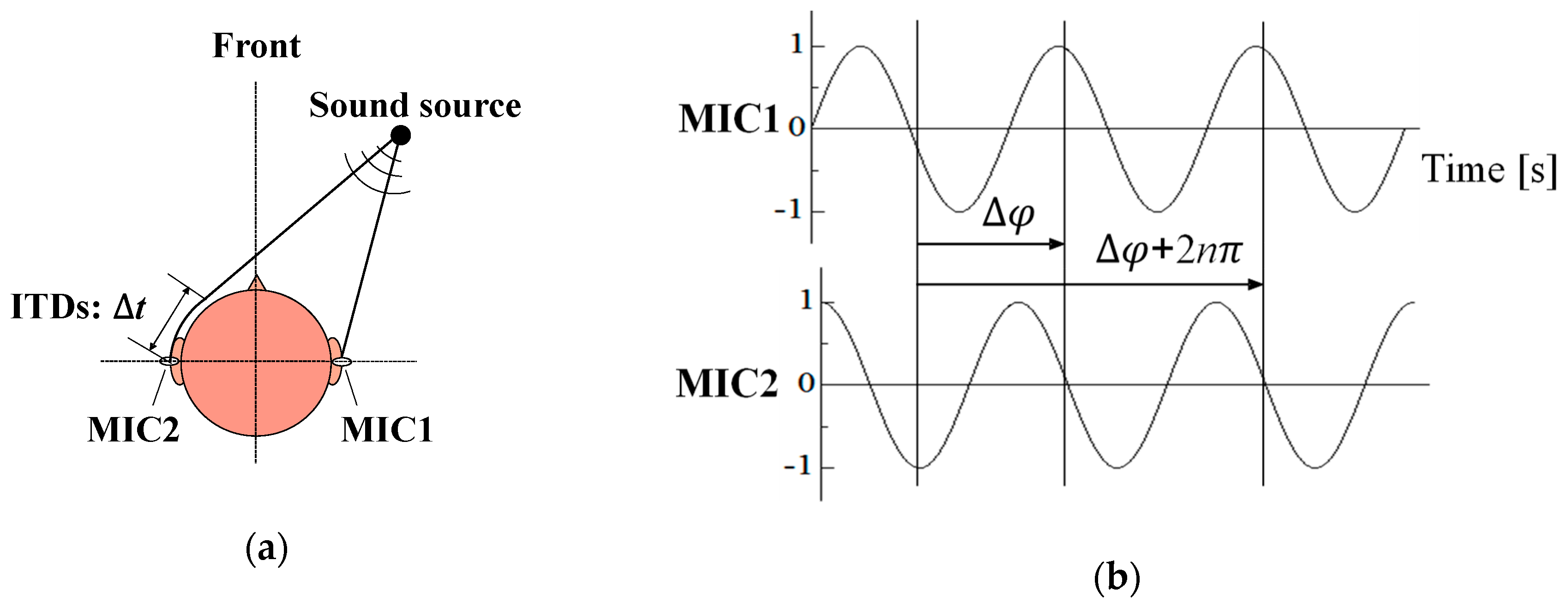
When sound radiates from a source, sound pressure propagates from the source to two ear microphones, Mic1 and Mic2, which were inserted into the right and left ears, respectively, as shown in Figure 1a. If the head is not facing the sound source, the sound arrives at Mic2 later than at Mic1. This arrival time lag is also called the ITD. It is desirable to identify the ITD from phase differences, since the phase is more redundant for detection, even under reverberating conditions, rather than the amplitude of the sound pressure. However, we are faced with the fact that the phase difference is ambiguous, which is explained, as follows. Figure 1b shows two waveforms of sound pressure at an arbitrary frequency. The waveform at Mic2 has a phase more delayed than that at Mic1. Thus, the phase difference of sound pressures can be defined as and also , since periodic phase repeats. The phase difference of sound pressure is generally defined as , where is an integer. This expression leads to ambiguous phase difference values due to the integer . The waveform at Mic2 is delayed when is positive and it is advanced when is negative, but we cannot determine whether the waveform is delayed or advanced, that is, whether is positive or negative.
2.2. Identification of ITDs.
In this section, true ITDs are distinguished from ambiguous ITDs. Two acoustical signals of and are detected with two microphones. Taking into account the phase difference ambiguity, the interaural phase difference of sound pressures at frequency is expressed as
where and are the respective spectra after the Discrete Fourier Transform (DFT) processing of , and is an integer whose value depends on frequency .
The interaural time difference of sound pressures is expressed as,
The arrival direction of sound radiated from a single sound source does not depend on frequency. Thus, the true ITD is calculated, as shown in (3), where the evaluation function is maximized as
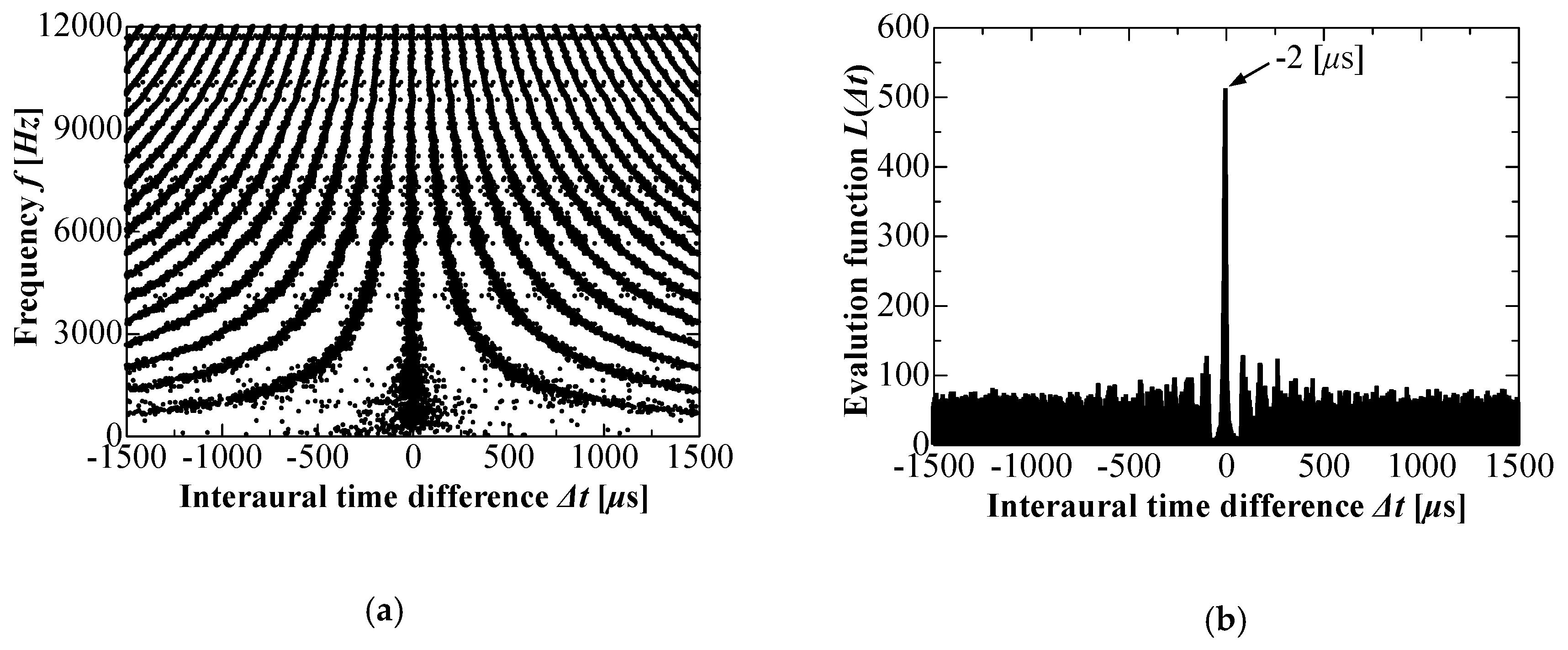
Figure 2a shows the interaural time differences calculated from the experimentally obtained phase differences of sound pressure at various frequencies when random noise is continuously radiated from one rear loudspeaker that was located in the direction +140° in a reverberation room. Many patterns of interaural time differences are evident. Multiple interaural time differences are calculated at frequencies that are higher than approximately 500 Hz due to integer . Figure 2b shows the histogram obtained from (3). The true ITD is estimated as 224 μs when the evaluation function is maximized and the loudspeaker is located in the direction +140°. This true ITD is physically frequency-independent, as shown in Figure 2a. Section 3 discusses the relation between the sound source direction and ITDs.
3. Humanoid Robot Turning Its Head Toward a Sound Source
In comparison with a person, the turning of a robot head can be more precisely controlled for tracking the location of a sound source. At first, to simplify the problem, we used a humanoid robot head that was fixed on a pan-tilt unit and was horizontally rotatable. The robot head was equipped with binaural microphones and precisely controlled by a workstation to horizontally rotate.
3.1. System Configuration and Flowchart of Robot Head Motion
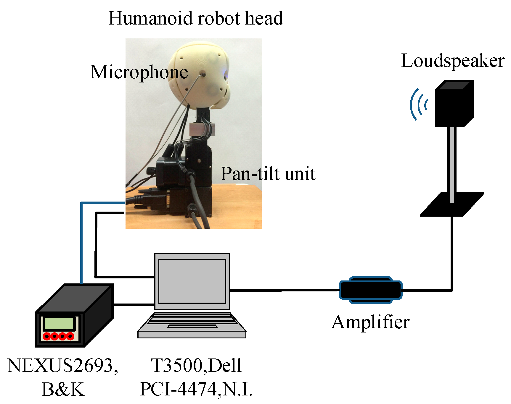
As shown in Figure 3, the ear microphones change their direction when the robot head rotates horizontally. A pre-recorded broadband noise is radiated from the loudspeaker. The acoustical signals are processed while using the workstation (GX280, Dell com) and an analogue-to-digital converter (PCI-4474, N.I.) with 24-bit resolution. The sampling frequency was 24 kHz and each frame period was 0.2 s, which included 4800 data points from each channel. The workstation controls the robot head to continuously track the loudspeaker. Figure 4 shows the flowchart for sound source tracking. The sound source direction is estimated from the true ITD, which is calculated from (1) and (2). The relation between true ITDs and source direction is discussed in Section 3.2.1. The robot head is controlled to rotate toward the estimated angle of the sound source any time when the estimated source direction exceeds the threshold range; otherwise, the head does not rotate. The threshold range is set from −10° to +10°. The robot head continuously tracks the sound source.
3.2. Experimental Results for Robot Head Motion
3.2.1. Relation between ITDs and Source Directions
We need to know the relation between the true ITD and source direction for identifying the source direction, after we estimate the true ITD. The relation between the sound source direction and ITD cannot be directly calculated, because sound does not always transmit along a straight line, and it is normally diffracted around the head or the outer ear of a person, as shown in Figure 1a. Though computer simulation is one solution, the relation between direction and ITD may depend on the size or shape of the head and body and the sound frequency. In this study, the relation between the sound source direction and the ITD was experimentally obtained. Figure 5 shows that the ITD varies for different sound source directions. The sound source direction is assigned to 0° or +90°, respectively, when the sound source is located in the front of the robot head or to its right. The ITD is proportional to the sound source direction in the frontal range from −90° to +90°. The slope of the function was approximated as 4.7 μs/deg. The sound source direction can be directly obtained from ITDs in Figure 5 within this range. In contrast, two source directions, A and B, provide one ITD value of 166 μs when the source direction is located towards the rear. This is called the “cone of confusion”, as shown in Figure 6. Each sound source located on the geometrical shape of the cone yields the same ITD value. Thus, the front, rear, upper, and lower sound sources cannot be located while only using the ITD obtained with two microphones [6,7]. We cannot identify the true direction of the sound source if we cannot solve the cone of confusion.
In this study, we focused on horizontal source localization and allowed for the binaural robot head to rotate horizontally. Subsequently, we introduced the assumption that the sound source is always located in front of the robot head and not in the rear when the robot head is moving. The robot head will continue to track the sound source in the frontal hemisphere step by step and stop moving when the robot head faces the sound source. However, as Boumann et al. reported, the cone of confusion cannot be directly solved when the ITD is zero [34]. As discussed in Section 4.2.3, the subject’s vision may solve the cone of confusion in such cases.
3.2.2. Robot Head Motion
We experimentally confirmed that our assumption that the sound source only exists in the frontal hemisphere during head movement would dynamically solve the cone of confusion. Two experiments were conducted under different initial conditions. In the first initial condition, the robot head was oriented +40° right with respect to the loudspeaker. Figure 7 shows the time response of the true ITD when the robot head was tracking sound from the loudspeaker. The robot head rotated +40° once after the sound started and stayed in this position. Figure 8 shows (a) the frequency characteristics of the ITDs and (b) the histogram of ITDs before motion at the initial moment that is labelled ① in Figure 7. The estimated ITD was 220 μs, corresponding to a source direction of 40°. Figure 9 shows (a) the frequency characteristics of ITDs and (b) the histogram of ITDs after head motion at the moment that is labelled ② in Figure 7. The value of ITDs changed from 220 μs to −2 μs. The robot head oriented itself toward the loudspeaker in one movement.
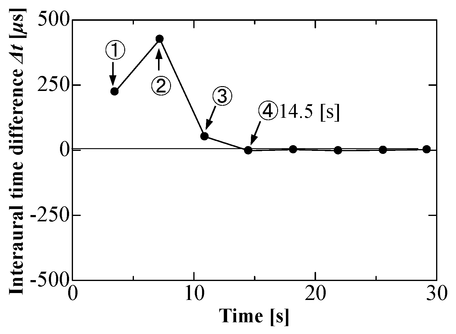
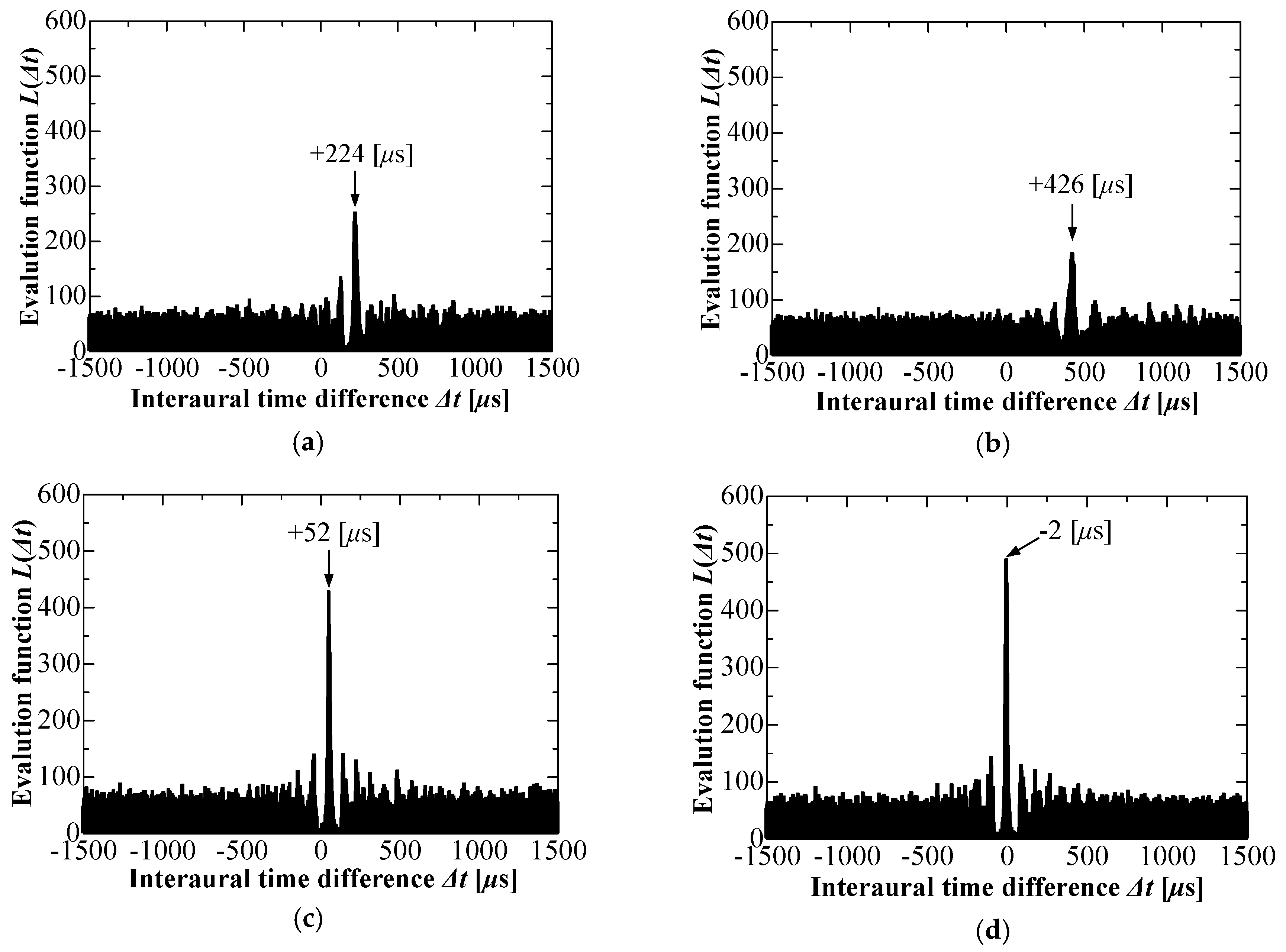
Next, we tested the case where the initial direction was to the right rear at +140°. This direction corresponds to an ambiguous frontal angle of +40°. The front-back confusion might not be solved with fixed ear microphones in this case. Figure 10 shows the time response of ITDs during the robot head motion. It was found that the robot head rotated three times to orient itself toward the rear loudspeaker. Figure 11a–d are the distributions of the histogram of various ITDs at the four moments that are labelled ①, ②, ③, and ④ in Figure 10. The ITDs increased once from 224 μs to 426 μs and then decreased to 52 μs and −2 μs. We will attempt to explain why the robot head made three separate motions. At first, the sound source direction was estimated as +40° (①), not the actual +140°, because we assumed that every sound source is located in the front. Afterwards, the robot head rotated +40°. After this motion, the sound source direction was estimated again. At this moment, the loudspeaker was actually located to the right rear by +100°. However, the source direction was repeatedly underestimated by +80° (②). Subsequently, the robot head rotated +80° (③). The total rotation angle was approximately 120° at this moment. The final estimated direction was +20°, which was less than 90°. The robot head rotated 20° to face the loudspeaker, as no ambiguous angle was left. The robot could distinguish between the front sound source and rear sound source by continuously searching for the sound source as its head rotated.
3.2.3. On the Effect of Sound Quality
In this section, we discuss the effect of sound quality on sound source tracking. Three different sounds—broadband noise, a motorcycle engine, and a truck engine—were recorded in advance. Each sound was replayed and continuously radiated from the loudspeaker that was placed at the same respective positions. Figure 12 shows the time responses of the ITDs under one of two initial source directions: right rear at +140°. In all cases, the robot head could orient toward the loudspeaker. There was no significant difference in the time response of ITDs among the three sound qualities. As described in Section 2, the ITDs are obtained from the phase difference of sound pressures. Thus, ITDs are not affected by sound quality, since the phase of sound pressure is independent of amplitude. It was found that the proposed system had good performance for various continuous sounds.
3.2.4. On the Effect of Distance to Sound Source
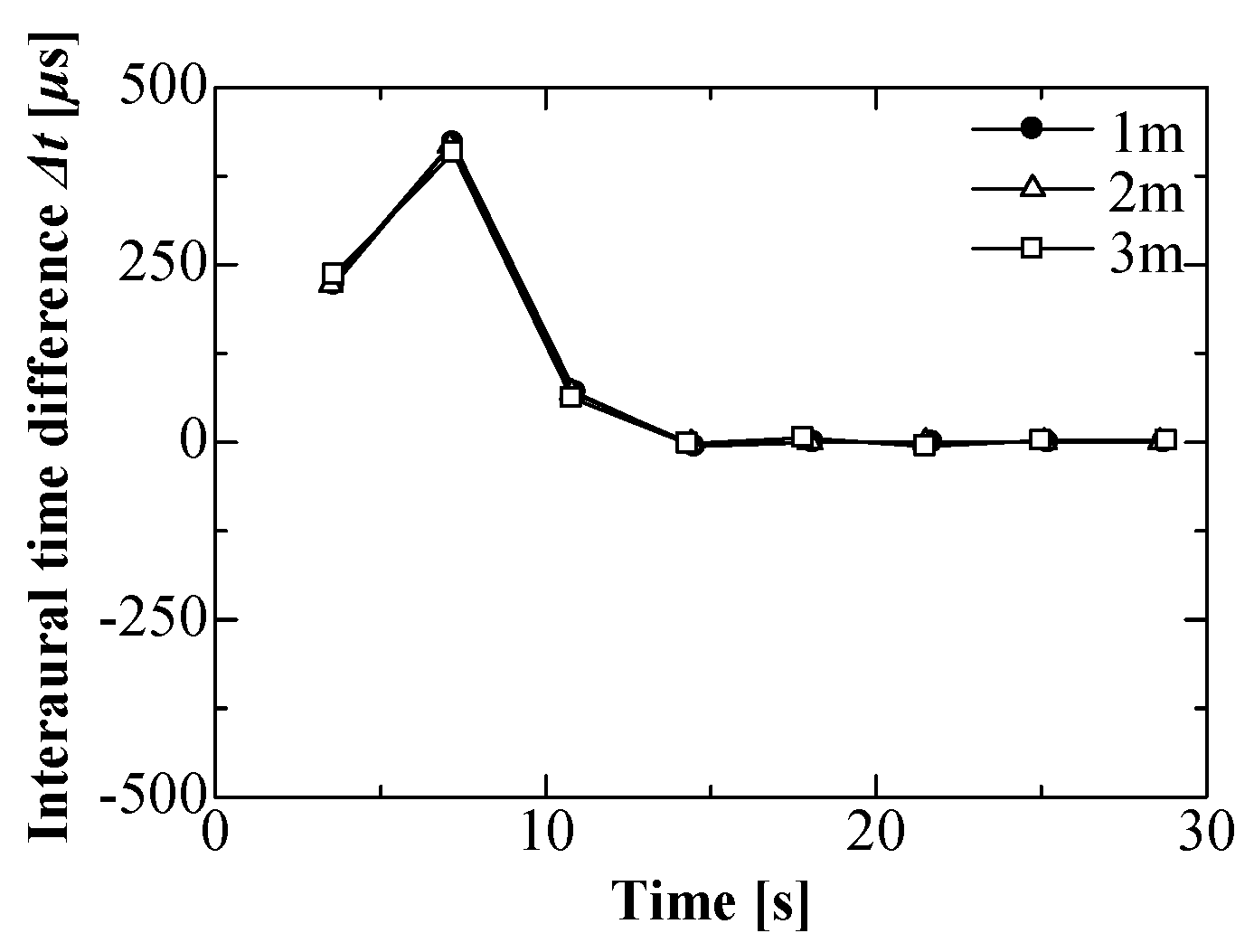
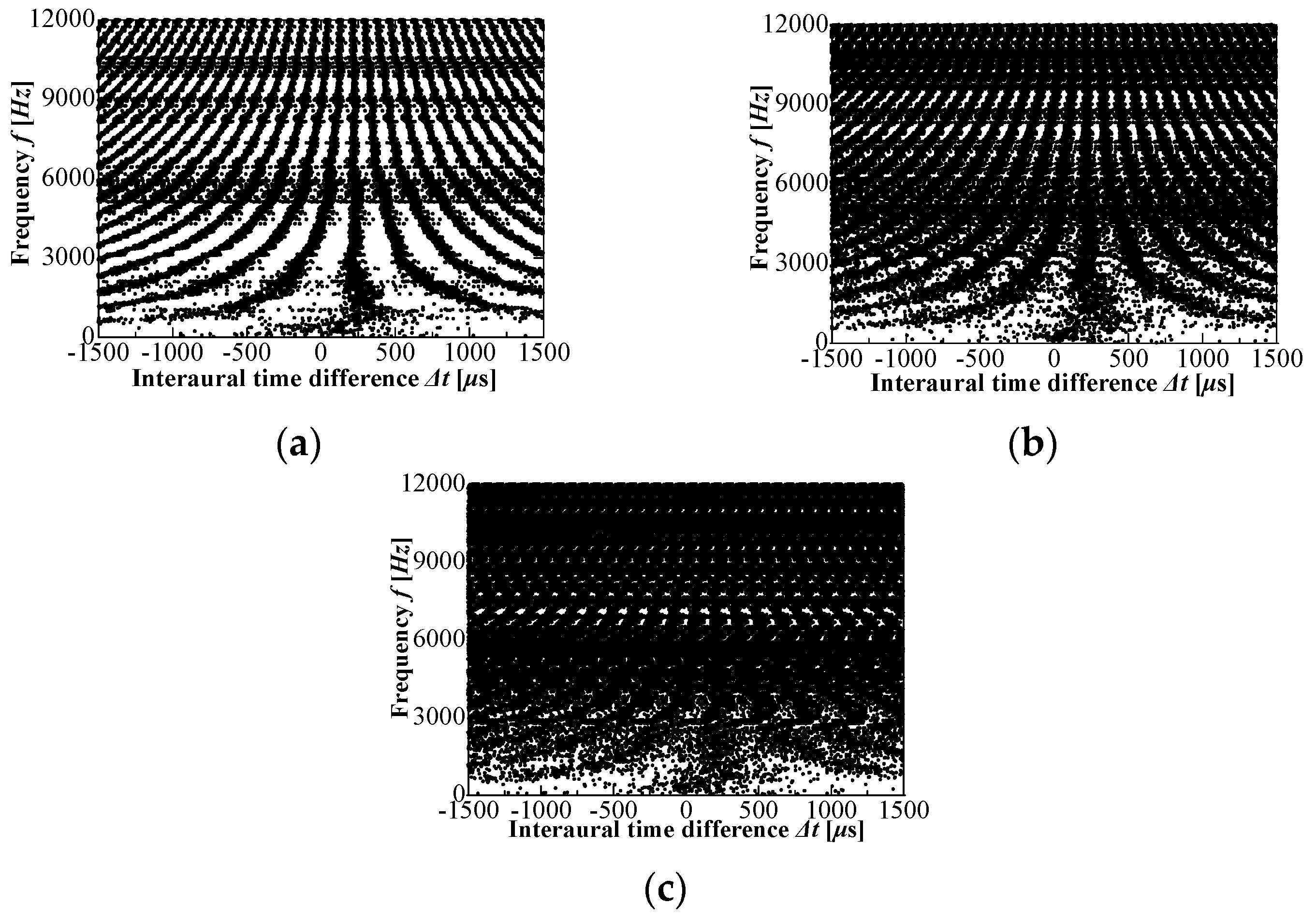
This section describes the effect of distance between the robot head and the loudspeaker on sound source tracking. Figure 13 shows the time responses of ITDs where the sound source was located at three different distances, 1 m, 2 m, and 3 m, in an initial direction of right rear at +140°. It was found that distance had no significant effect on the robot head tracking for the sound source. Three ITD frequency spectra are compared at the initial condition (before the rotation of the robot head) for different distances in Figure 14a–c. More dispersion was observed at longer distances between the loudspeaker and robot head at higher frequencies, since minimal sound diffracts around the robot head at high frequencies. These dispersions may be caused by sounds reflected surrounding objects/obstacles. It is more suitable to estimate ITDs for a rear sound source at lower frequencies of approximately 3 kHz.
4. Hearing Assist System for Turning Subject Toward a Sound Source
In previous sections, we discussed turning a humanoid robot head toward the sound source. A wearable hearing assist system for humans is described in this section. The robot can rotate its head easily and precisely to the sound source after the estimation of the sound source direction. Several additional processes are needed to inform the wearer of the estimated source direction and notify the wearer regarding whether the direction of his or her head is correct or not at any particular moment in the case of the impaired person who wears the hearing support system. In comparison with the humanoid robot system, these processes are added after the ITDs are estimated. A person cannot control his head or body to precisely rotate to a specific angle. Thus, in this study, the system notified the subject as to hemisphere contains the sound source, instead of the angle to the sound source. The subject can tactilely perceive which side contains the sound source by feeling alternating vibrations on his or her shoulders. When both of the vibrators simultaneously vibrate, the wearer knows that he or she is facing the sound source.
4.1. System Configuration and Flowchart of Subject’s Motion
The measuring system is shown in Figure 15. The subject carried only a field-programmable gate array (FPGA) module (MyRIO-1500, National Instruments) with a battery and wore a vest that was equipped with a vibrator on each shoulder and an earphone type microphone (MDR-EX3IBN, Sony) in each ear. The FPGA module is a convenient microcomputer that is equipped with two channels of 12-bit resolution analogue-to-digital converter. The subject was a young male who was not completely deaf. The subject additionally wears two earplugs for preventing the subject from hearing environmental sounds. The measurement and data processing of the acoustical signals were performed by the field-programmable gate array (FPGA) module, which was connected with a personal computer to display and record the collected data. The sampling frequency was 12 kHz and each frame period was 0.4 s, which included 4800 data points from each channel. The sounds of various qualities were radiated from the loudspeaker, which was positioned at a height of 0.83 m. Sounds were recorded in advance and replayed by the personal computer. The loudspeaker was located 1 m away from the subject. Figure 16 shows the appearance of the subject wearing the vest and sound processing gears. The subject was asked to turn his head to the sound source according to the alternate vibration of the vibrators on his shoulders after the sound was radiated from the loudspeaker. The time responses of ITDs and the activation of vibrators were synchronously measured while the subject turned his head to the sound source after the sound was radiated. Two types of sound were radiated from the loudspeaker: continuous motorcycle engine and the repeated calling of the subject’s name.
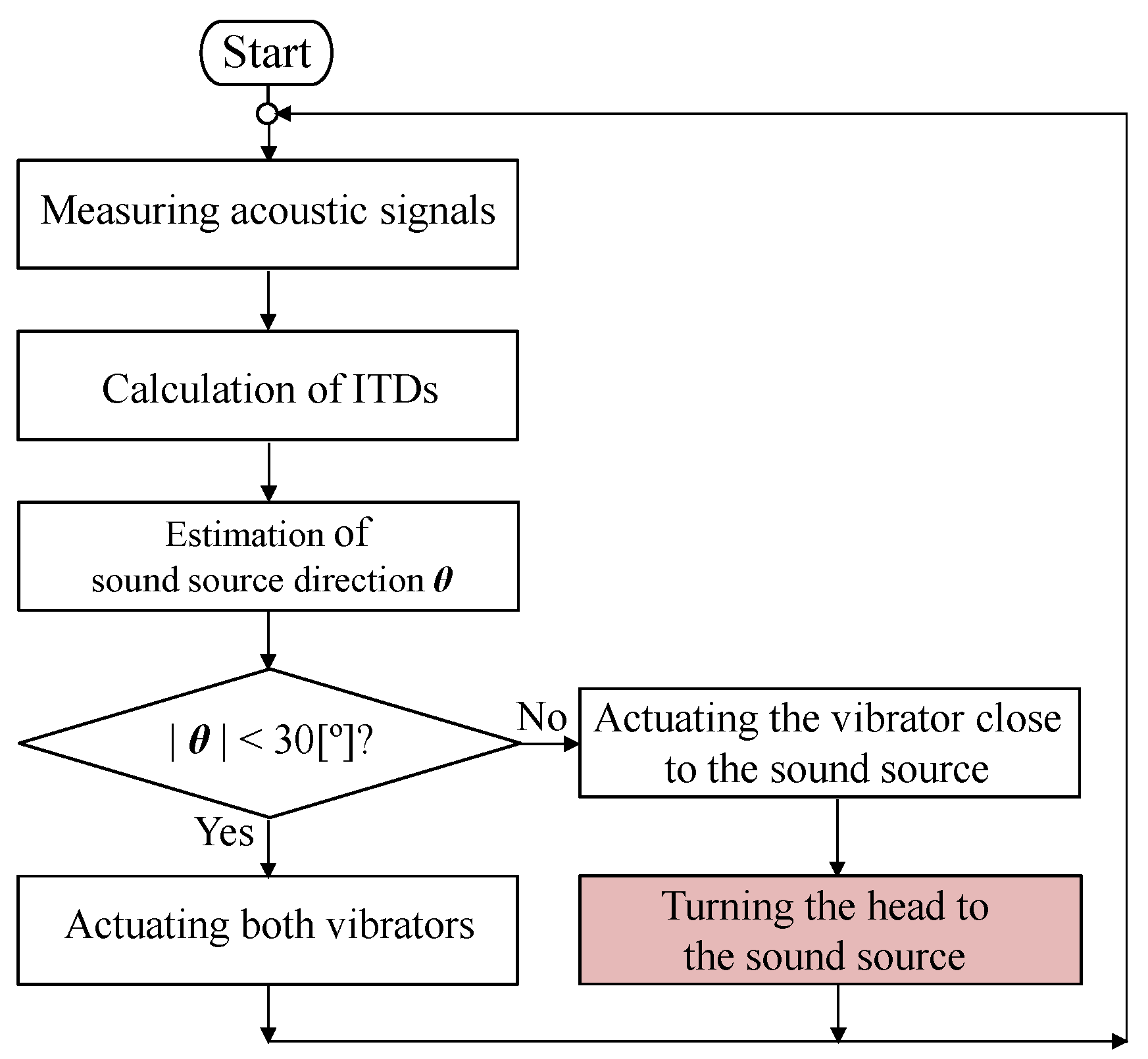
Figure 17 shows the flowchart for tracking the sound source with the setup in Figure 15. True ITDs are calculated by (1) and (2) while using the FPGA module from the acoustical signals detected at both ear microphones. The system alternately vibrates the vibrator continuously on the shoulder that is closer to the sound source if the absolute value of the ITDs is larger than the threshold. The subject was asked to continue turning his head toward the vibrating side. Finally, both of the vibrators continuously vibrated when the absolute value of ITDs was lower than the threshold. The threshold value was different from that used for the humanoid robot head. The human horizontal viewing angle is estimated as a maximum of 200° with both eyes. The vision of each eye has a higher resolution and easy concentration at the center of vision. Humans can easily and stably gaze at an object from ±30° to ±40°, as shown in Figure 18 [47]. In this study, the threshold was defined as a human horizontal viewing angle of 30°. In this range, humans can visually recognize the object easily and quickly. As mentioned for the humanoid robot head in Section 3.2.1, the front-back confusion cannot be directly solved when the ITD is zero. If we assume that the subject is hearing-impaired but it has normal vision, the subject could use vision to distinguish between front and rear sources. In other words, acoustical front-back confusion does not exist when vision is available.
4.2. Experimental Results for Subject’s Motion Wearing the Assist System
4.2.1. Relation between ITDs and Source Directions
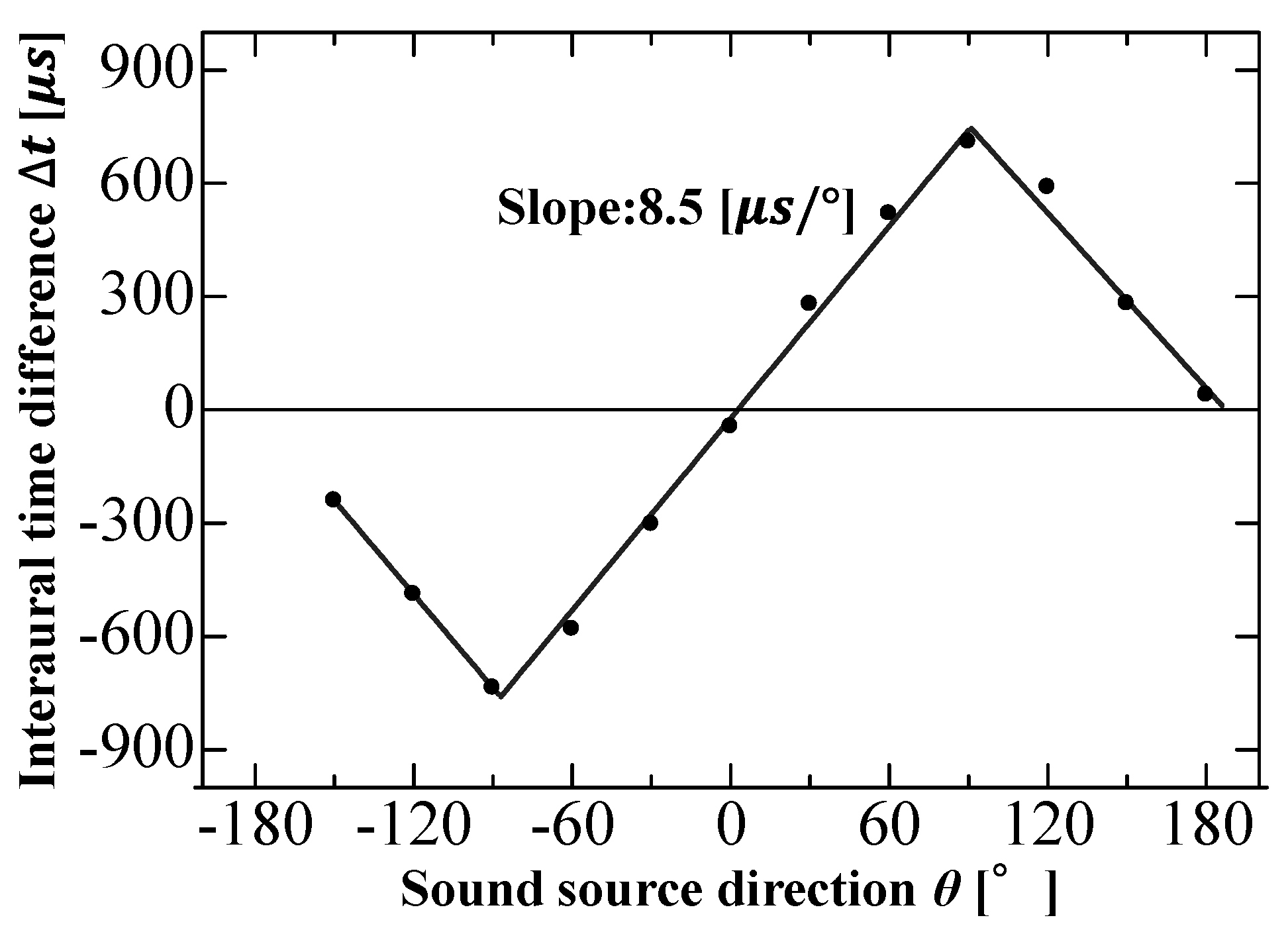
Here, we discuss the relation between the sound source direction and ITD for a subject that is wearing the assist system. Continuous broadband motorcycle noise was radiated from the loudspeaker 1 m from the subject. The ITDs were calculated for various directions of the loudspeaker. Figure 19 shows the relation between the sound source direction and the ITDs that were experimentally obtained. Similar to that of humanoid robot head, the sound source direction was proportional to ITDs in the range −90° to +90°. The slope of the approximation line was 8.5 μs/deg, which was larger than that for the robot head (4.7 μs/deg). The reason is that the distance between the subject’s ears is larger than the distance between the microphones in the robot head. The interaural distance of the subject was approximately 0.182 m in this case, but we note that the interval between the ears is person-specific. Thus, the ITDs might vary for different individuals, even for experiments that were conducted under the same conditions. The effect of interval between ears on the value of ITDs is described in the next section.
4.2.2. On the Effect of Interval between Ears
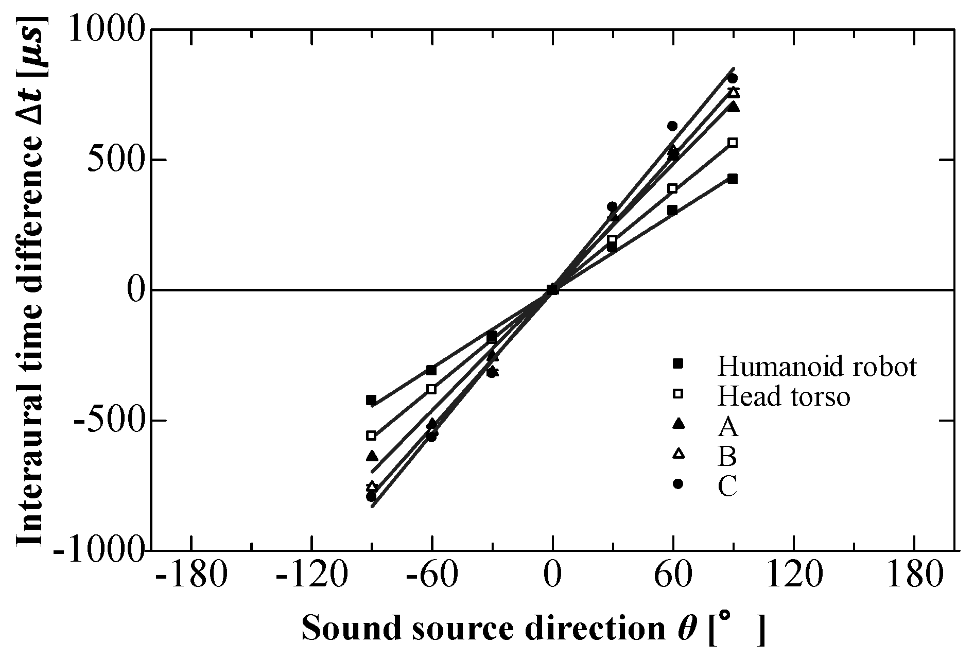
The value of ITDs depends on the ear interval due to personal differences in the size and shape of the head and outer ear, as shown in Figure 1a. Five different between-ear intervals are shown in Table 1 for a humanoid robot, head, and torso simulator, and three subjects (A, B, and C). Subject C has a much wider interval, twice that of the humanoid robot. Figure 20 shows the relation between the sound source direction and ITDs for the intervals that are listed in Table 1. Both the values of ITDs and the slopes of approximation lines were larger for larger between-ear intervals. These results indicate that the sound source direction is probably overestimated for smaller between-ear intervals. However, there were no significant differences in ITDs between the intervals for smaller sound source directions. Not the precise source direction, but which hemisphere contains the sound source is important in the present system. Thus, the effect of interval between ears on sound source tracking is negligible.
4.2.3. On the Effect of Vision
Our approach rests on the premise that the system users have hearing impairment but no vision impairment. It is probably useless for this system to convey the sound source direction to someone who is both hearing-impaired and blind, since such a person cannot obtain the visual information that is needed to escape from dangerous situations. If a hearing-impaired person can utilize their vision, they may be only able to find the sound source by their vision. For example, they can also find the target loudspeaker while only using vision. The effect of vision on tracking the sound source is discussed in this section. The subject put earplugs in both ears and additionally covered his eyes with an eye mask. The experimental results with and without an eye mask were compared.
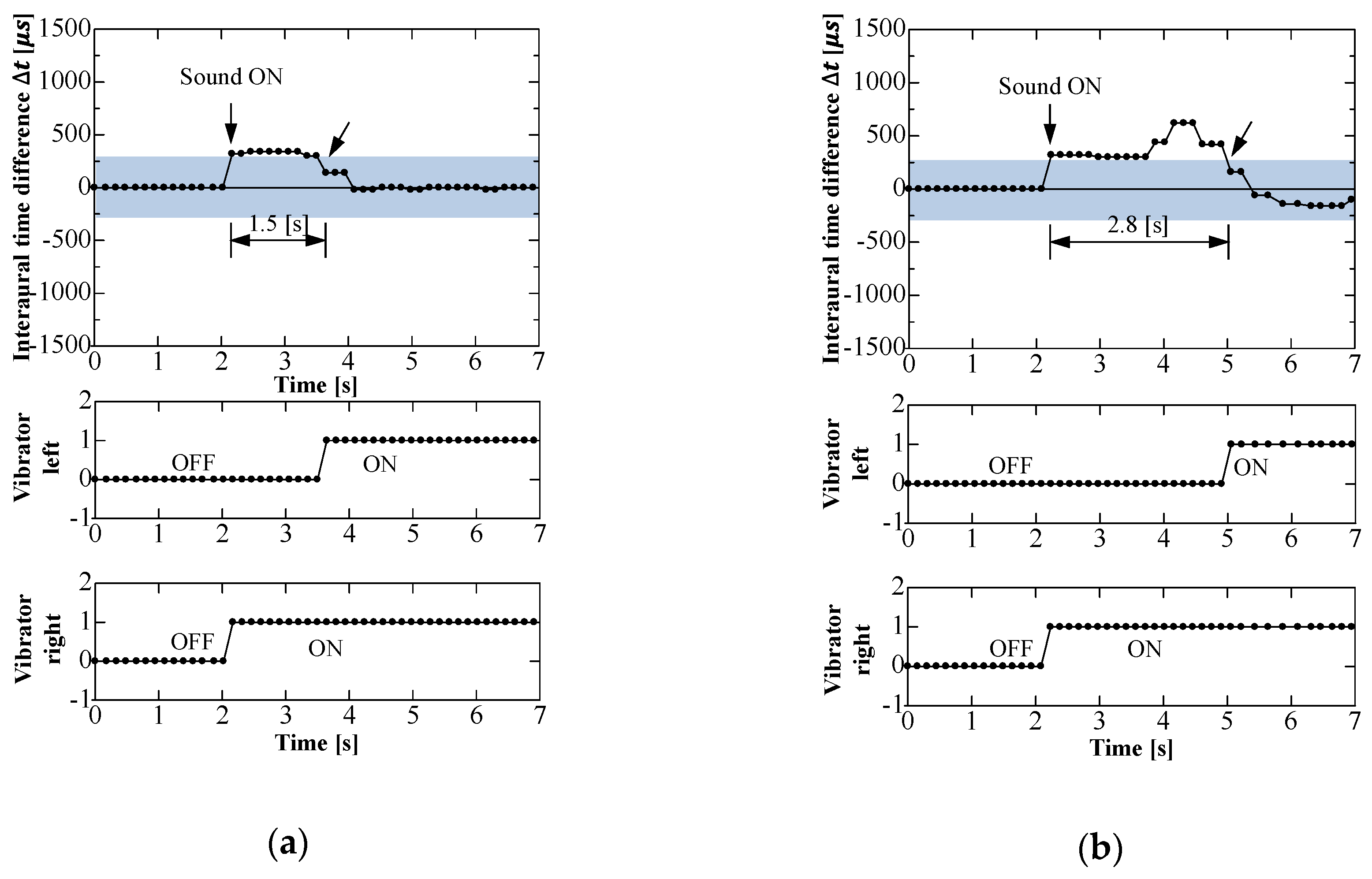
First, in the case of not wearing an eye mask, Figure 21 shows the time responses of ITDs and activation of both vibrators on the shoulders. The measurements were obtained for two different sound source directions: (a) in the front right at +40° and (b) in the rear right at +140°. These two source directions provided the same ITD value of 360 μs at the moment when the sound was initially radiated. In the case of +40°, the ITDs increased up to 360 μs and gradually decreased as the subject turned his head toward the loudspeaker in response to the right vibrator. Finally, the subject noticed that the loudspeaker was in front of him when both of the vibrators vibrated. For the rear loudspeaker, time responses of ITDs were completely different from those in the case of +40°. The ITDs increased up to 360 μs when the sound initially radiated, and then gradually decreased after increasing again by up to 750 μs. This ITD peak corresponded to a sound source on the right at +90°. The subject continued to turn his head toward the loudspeaker in response to continuous vibration on his right shoulder, as mentioned in Section 4.1. When both of the vibrators vibrated, the subject knew that the target was in front of him. It took approximately 1.5 s to turn his head toward the front right loudspeaker. It took approximately 2.8 s to track sound from the rear right loudspeaker. The proposed system, which is only equipped with two microphones, can distinguish between the front and rear sound sources, because it continues to repeatedly track the target in real time if the first tracking motion is unsuccessful.
Next, Figure 22 shows the time responses of ITDs and activation of both vibrators when the subject was wearing an eye mask. The measurements were obtained for a sound source direction of +140°, as in Figure 21b. It took the subject 1.5 s longer than the time that is needed without an eye mask (2.8 s), as shown in Figure 21b, to turn his head toward the loudspeaker. When the subject could utilize vision, this seemed to help him more quickly track the target sound source, especially when the target comes into view, and it may shorten the time that is needed to identify the direction of the target source.
4.2.4. On the Effect of Sound Quality
Section 4.2.3 utilized continuous broadband noise. In this section, the effect of sound quality on performance of the proposed system is discussed. In a real-world situation, we sometimes hear our name called out by someone behind us. Subsequently, we turn our head toward the calling sound and find the person to communicate with them. Measurements were obtained for the case where the sound quality was intermittent name calling to determine whether the proposed system is suitable for such cases. The sound was recorded as a person called the name twice in 2-s intervals, and it was replayed through a loudspeaker.
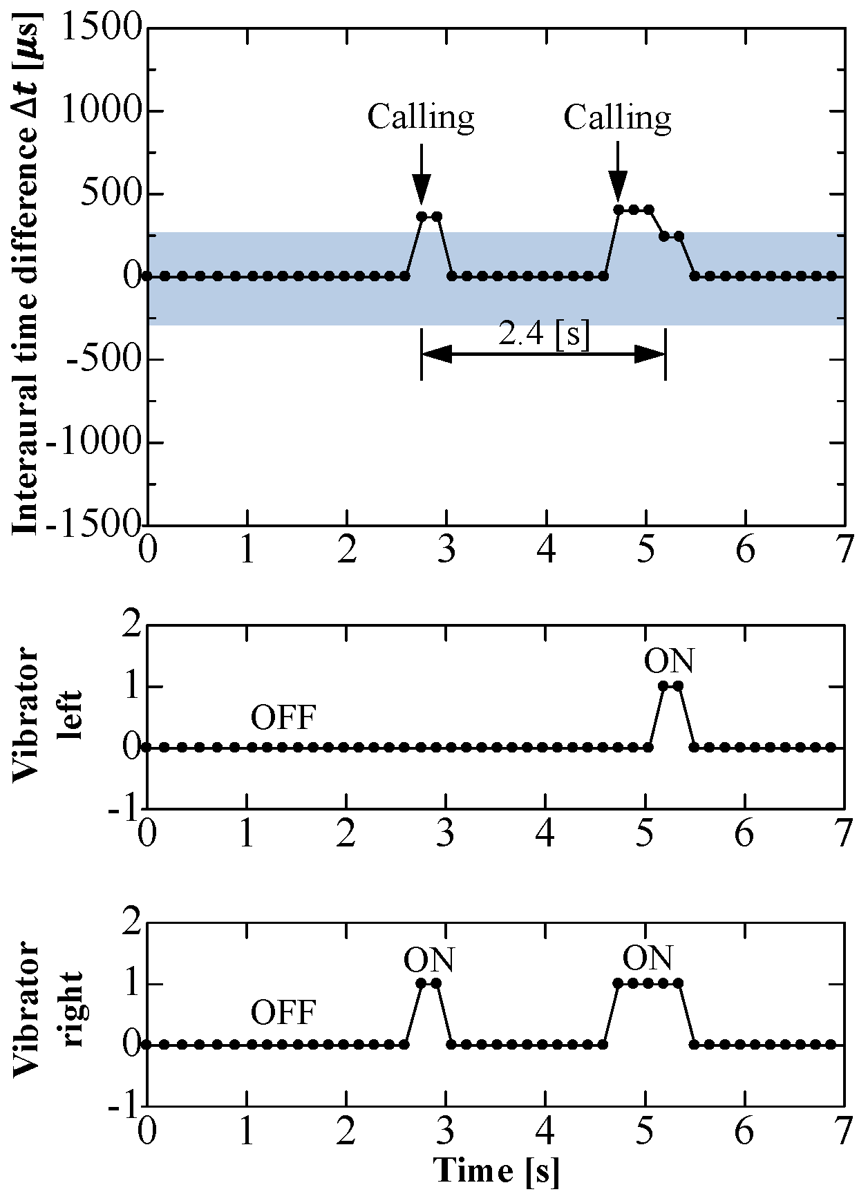
Figure 23 shows the time responses of ITDs and the activation of both vibrators on the shoulders. The measurements were obtained for sound source direction: rear right at +140°. Comparison with the time responses, as shown in Figure 21b, shows that ITD determination and the activation of both vibrators were also intermittent. They were only activated when the sound was radiating. The subject was asked to continue turning his head toward the sound source after the vibrator had stopped vibrating. The values of ITDs decreased below the threshold and both of the vibrators were activated at the second calling in Figure 23. The periods during which the subject turned his head toward the target source were similar to those in the case of continuous broadband noise. The subject could still turn his head toward the target source and engage in communication, although the activation of vibrators was intermittent.
5. Discussion
A new wearable hearing-assist system for the deaf was developed. The system identified the direction of a sound source using the ITDs of sound pressure and notified the subject as to which hemisphere contained the sound source by the vibration of two vibrators that were attached at the shoulders.
To solve the “cone of confusion” on sound source localization [6,7], Wallach suggested that, when the head rotates during a continuous sound, several horizontal directions to the same source are obtained, and humans can resolve ambiguous source positions [10]. The head rotation may assist in the localization of ambiguous sound source positions, although head rotation is not the only way to solve such ambiguity [11,12,13,14,15]. The proposed system, which was only equipped with two microphones, could distinguish a front source from a rear source, since it continued to repeatedly track the target in real time if the first tracking motion failed.
Baumann presented a simple and effective mathematical model for localizing a 2D sound source. In their model, the microphone rotation depends on the sign of the ITDs [18]. We adapted Baumann’s simple model to our wearable hearing-assist system for notifying the subject regarding which hemisphere has the sound source. The system continues to identify the hemisphere containing the source to the subject until the subject faces the sound source. Consequently, the system could resolve ambiguous source positions. Our experimental results supported the validity of Baumann’s simple model. The proposed system can also track the probably for moving sound sources, even while the head is rotating. By several experiments on sound source localization while using the robot head, the reason why the robot or the subject could identify the rear sound source was estimated that the angle in front was selected from ambiguous angles and the robot head or the subject’s head was rotated toward the sound source. Our major assumption was that the sound source is always in the front of robot and not in the rear. Why can “cone of confusion” be resolved under this assumption? In conventional manners, the robot head was turned toward sound source after identifying the sound source location once. Both of the processes are separately and sequentially performed. We adapted strategy to dynamically search for the sound source. The robot searched the sound source during the motion of its head simultaneously. We do not know which angle is correct before the motion. If the robot head rotates by the assumed frontal angle, the ITDs will be zero when our assumption is correct. The sound source would be located to the rear when the ITDs is not zero. When the sound source is located to the rear, the robot head is forced to rotate by +90°. All of the motions are steps in the process and are not pointless.
The absolute values of ITDs were larger for wider intervals between two ears. The sound source direction is probably overestimated when the interval between the two ears is smaller. There were no significant differences in ITDs between the intervals for smaller sound source direction angles. Not the precise source direction, but which hemisphere contains the sound source, is important in the present system. Thus, the effect of interval between ears on sound source tracking is negligible.
Our approach rests on the premise that the system users have a hearing impairment but no vision impairment. It is probably useless for this system to convey the sound source direction to someone who is both hearing-impaired and blind, since such a person cannot obtain the visual information that is needed to escape from dangerous situations. When the subject can utilize vision, this may help in the tracking the location of the target sound source, especially if the target comes into view, and it may shorten the tracking period.
The effectiveness of Wallach’s head rotation depends on the sound duration. Head rotation is effective for long durations, but its effectiveness is limited for short sound durations. Measurements were obtained when the subject heard a name called twice at 2-s intervals for checking the proposed system suitability when the sound quality is intermittent. Though the activation of vibrators was intermittent, the subject could orient himself toward the target source correctly within approximately 2.8 s.
6. Conclusions
We developed a new wearable hearing-assist system for the deaf. The system identifies the direction of a sound source while using short-term ITDs of sound pressure and notifies the subject as to which hemisphere contains the sound source by the vibration of two vibrators that were attached at the shoulders. An algorithm that was similar to the auditory mechanism of a Barn owl was utilized for identifying the direction of sound source using the ITDs. The results can be summarized, as follows:
- The proposed system, which is only equipped with two microphones, can distinguish a front source from a rear source, since it continues to repeatedly track the target in real time if the first tracking motion fails. The system continuously checks the subject’s head direction using ITDs, which corresponds to subject’s head direction as same as hearing-dog will do. The system also probably tracks moving sound sources.
- The absolute values of ITDs were larger for wider intervals between two ears. The sound source direction is probably overestimated when the interval between the two ears is smaller. There were no significant differences in ITDs between the intervals for smaller sound source direction angles.
- When the subject can utilize vision, this may help in tracking the location of the target sound source, especially if the target comes into view, and it may shorten the tracking period.
- For checking the proposed system suitability when sound quality is intermittent, the measurements were obtained when the subject heard a name called twice at 2-s intervals. The subject could orient himself toward the target source correctly within approximately 2.8 s although the activation of vibrators was intermittent.
In this study, an algorithm that was similar to the auditory mechanism of a Barn owl was utilized for identifying the direction of sound source while using short-term ITDs. This redundant algorithm made temporal measurements possible in the reverberative room. The resulting peaks of the ITD histogram may indicate several source directions individually when each sound is intermittent over time by aggregating ITDs over time. We experimentally confirmed that the performance of the developed system was valid for a loudspeaker distance of 3 m in a room. Hearing-impaired people would notice various sound sources, such as the ringing of alarm or telephone, by the use of our hearing-assist system in a room. The performance of our system would be tested outdoors in the future. Our research goal is to develop an outdoor type of wearable hearing-assist system that detects sound and localizes the sound source and informs the wearer of the position of the sound source, even outdoors. If such system would be developed, hearing-impaired people could turn their face toward the sound of a car as the same as ordinary person when they cross the road. Our assist system would expand hearing-impaired people’s abilities more. Every human-assist systems will connote ethical problems as the same as autonomous car with respect to the risk of accident with car. A display on a screen of mobile phone is often an easy and useful way to convey information. However, visual display is not suitable as a man-machine interface, because the hearing-impaired person needs their vision to discern the surrounding environment. Thus, we used vibrators for conveying information. Especially in the use of outdoor in near future, vibration will be better for conveying information on the road for reducing risk of accident with cars or motorcycles. Our system with two vibrators could convey which side car exists. It will be important to rapidly inform the wearer of approaching objects, since cars and motorcycles travel at high speed. If the system could clarify sound qualities and provide alerts with different patterns of vibration, the system would more closely mimic the behaviour of a hearing dog. Such functional enhancements will be the subject of future work.
Funding
This research received no external funding.
Acknowledgments
Author thanks I Syou especially for developing the present system, conducting several experiments, and processing data as a graduate student.
Conflicts of Interest
The authors declare no conflict of interest.
References
- Symptoms of Hearing Loss & Degree of Hearing Loss, WebMS. Available online: https://www.webmd.com/a-to-z-guides/hearing-loss-causes-symptoms-treatment#1 (accessed on 17 June 2019).
- Furuta, S.T.; Nakamura, T.; Iwahiri, Y.; Fukui, S.; Kanoh, M.; Yamada, K. Consideration of life rhythm for hearing-dog robots searching for user. In Proceedings of the TAAI, Taichung, Taiwan, 30 November–2 December 2018. [Google Scholar]
- Kudo, H.; Koizumi, T.; Nakamura, T.; Kanoh, M.; Yamada, K. Behaviour model for hearing-dog robot. In Proceedings of the IEEE-ICIS&ISIS, Sapporo, Japan, 25–28 August 2016. [Google Scholar]
- Roman, N.; Wang, D.L. Binaural tracking of multiple moving sources. IEEE Trans. Audio Speech Lang. Process. 2008, 16, 728–739. [Google Scholar] [CrossRef]
- Knapp, C.; Carter, G. The generalized correlation method for estimation of time delay. IEEE Trans. Acoust. Speech Signal Process. 1976, 24, 320–327. [Google Scholar] [CrossRef] [Green Version]
- Shinn-Cunningham, B.G.; Stantarelli, S.; Kopco, N. Tori of confusion: Binaural localization cues for sources within reach of a listener. J. Acoust. Soc. Am. 2000, 107, 1627–1636. [Google Scholar] [CrossRef] [PubMed]
- Archer-Boyd, A.W.; Whitmer, W.M.; Brimijoin, W.O.; Soraghan, J.J. Biomimetic direction of arrival estimation for resolving front-back confusions in hearing aids. J. Acoust. Soc. Am. 2015, 137, 360–366. [Google Scholar] [CrossRef] [PubMed]
- Wallach, H. On sound localization. J. Acoust. Soc. Am. 1919, 10, 270–274. [Google Scholar] [CrossRef]
- Hartmann, W.M. How we localize sound. Phys. Today Am. Inst. Phys. 1999, 52, 24–28. [Google Scholar] [CrossRef]
- Wallach, H. The role of head movements and vestibular and visual cues in sound localization. J. Exp. Psychol. 1940, 27, 339–368. [Google Scholar] [CrossRef]
- Turlow, W.R.; Mangels, J.W.; Runge, P.S. Head movement during sound localization. J. Acoust. Soc. Am. 1967, 42, 489–493. [Google Scholar] [CrossRef] [PubMed]
- Pollack, I.; Rose, M. Effect of head movement on the localization of sounds in the equatorial plane. Percep. Psychophys. 1967, 2, 591–596. [Google Scholar] [CrossRef]
- Wightman, F.L.; Kistler, D.J. Resolution of front-back ambiguity in spatial hearing by listener and source movement. J. Acoust. Soc. Am. 1999, 105, 2841–2853. [Google Scholar]
- Usagawa, T.; Saho, A.; Imamura, K.; Chisaki, Y. A solution of front-back confusion within binaural processing by an estimation method of sound source direction on sagittal coordinate. In Proceedings of the IEEE/TENCON, Bali, Indonesia, 21–24 November 2011. [Google Scholar]
- Kyo-Sik, K.; Hyung-Tai, C. Distinction of front/back direction algorithm for effective detection of a speaker position. In Proceedings of the IEEE/CISP, Sanya, Hainan, China, 27–30 May 2008. [Google Scholar]
- Ma, N.; May, T.; Wierstorf, H.; Brown, G. A machine-hearing system exploiting head movements for binaural sound localization in reverberant conditions. In Proceedings of the IEEE/ICASSP, Brisbane, QLD, Australia, 19–24 April 2015. [Google Scholar]
- Bustamante, G.; Danes, P. Multi-step-ahead information-based feedback control for active binaural localization. In Proceedings of the IEEE/RSJ IROS, Vancouver, BC, Canada, 24–28 September 2017. [Google Scholar]
- Bustamante, G.; Danes, P.; Forgue, T.; Podlubne, A. A one-step-ahead information-based feedback control for binaural active localization. In Proceedings of the EUSIPCO, Budapest, Hungary, 29 August–2 September 2016; pp. 1013–1017. [Google Scholar]
- Perrett, S.; Noble, W. The contribution of head motion cues to localization of low-pass noise. Percept. Psychop. 1997, 59, 1018–1026. [Google Scholar] [CrossRef] [Green Version]
- Bustamante, G.; Portello, A.; Danes, P. A three-stage framework to active source localization from a binaural head. In Proceedings of the IEEE/ICASSP, Brisbane, QLD, Australia, 19–24 April 2015; pp. 5620–5624. [Google Scholar]
- Shinn-Cunningham, B.G.; Kopco, N.; Martin, T.J. Localizing nearby sound sources in a classroom: Binaural room impulse response. J. Acoust. Soc. Am. 2005, 117, 3100–3115. [Google Scholar] [CrossRef] [PubMed]
- Hu, J.S.; Liu, W.H. Location classification of nonstationary sound sources using binaural room distribution patterns. IEEE Trans. Audio Speech Lang. Process. 2009, 17, 682–692. [Google Scholar] [CrossRef]
- Nix, J.; Holmann, V. Sound source localization in real sound fields based on empirical statistics of interaural parameters. J. Acoust. Soc. Am. 2006, 119, 463–479. [Google Scholar] [CrossRef] [PubMed]
- Brown, G.J.; Harding, S.; Barker, J.P. Speech separation on the statistics of binaural auditory features. In Proceedings of the IEEE/ICASSP, Toulouse, France, 14–19 May 2006. [Google Scholar]
- Shimoyama, R.; Sho, I. Room volume estimation based on ambiguity of short-term interaural phase differences using humanoid robot head. Robotics 2016, 5, 16. [Google Scholar] [CrossRef]
- Chen, K.; Geiger, J.T.; Helwani, K.; Taghizadeh, M.J. Localization of sound source with known statistics in the presence of interferers. In Proceedings of the IEEE/ICASSP, Shanghai, China, 20–25 March 2016. [Google Scholar]
- Murota, Y.; Kitamura, D.; Koyama, S.; Saruwatari, H.; Nakamura, S. Statistical modeling of binaural signal and its application to binaural source separation. In Proceedings of the IEEE/ICASSP, Brisbane, QLD, Australia, 19–24 April 2015. [Google Scholar]
- Shimoyama, R.; Yamazaki, K. Multiple acoustic source localization using ambiguous phase differences under reveberative conditions. Acoust. Sci. Tech. 2004, 25, 446–456. [Google Scholar] [CrossRef]
- Shimoyama, R.; Yamazaki, K. Computational acoustic vision by solving phase ambiguity confusion. Acoust. Sci. Technol. 2009, 30, 199–208. [Google Scholar] [CrossRef] [Green Version]
- Wang, D.; Brown, G.J. Computational auditory scene analysis. In Piscataway; John Wiley & Sons: Hoboken, NJ, USA, 2006. [Google Scholar]
- Raspaud, M.; Viste, H.; Evangelista, G. Binaural localization by joint estimation of ILD and ITD. IEEE Trans. Audi Speech Lang. Process. 2010, 18, 68–77. [Google Scholar] [CrossRef]
- Shimoyama, R. Effect of sound diffraction on interaural time difference using head and torso. Proc. Forum on Information and Technology (In Japanese); Tottori, Japan, 5 August 2013; pp. 429–430. Available online: https://ipsj.ixsq.nii.ac.jp/ej/?action=repository_uri&item_id=152201&file_id=1&file_no=1 (accessed on 17 June 2019).
- Fujii, F.; Hogaki, N.; Watanabe, Y. A simple and robust binaural sound source localization system using interaural time difference as a cue. In Proceedings of the IEEE-ICMA, Takamatsu, Japan, 4–7 August 2013; pp. 1095–1101. [Google Scholar]
- Baumann, C.; Rogers, C.; Massen, F. Dynamic binaural sound localization based on variations of interaural time delays and system rotations. J. Acoust. Soc. Am. 2015, 138, 635–650. [Google Scholar] [CrossRef]
- Ross, D.A.; Blasch, B.B. Wearable interfaces for orientation and wayfinding. In Proceedings of the ASSETS’00, Decatur, GA, USA, 13–15 November 2000; pp. 193–200. [Google Scholar]
- Spelmezan, D.; Jacobs, M.; Hilgers, A.; Borchers, J. Tactile motion instructions for physical activities. In Proceedings of the CHI2009, Boston, MA, USA, 4–9 April 2009. [Google Scholar]
- Yatani, K.; Banovic, N.; Truong, K. SpaceSense: Representing geographical information to visually impaired people using spatial tactile feedback. In Proceedings of the CHI2012, Austin, TX, USA, 5–10 May 2012. [Google Scholar]
- Jiang, I.; Ishikawa, Y.; Lindsay, J.; Hannaford, B. Design and optimization of support structures for tactile feedback. In Proceedings of the IEEE/WHC, Daejeon, Korea, 14–17 April 2013. [Google Scholar]
- Vaijapurkar, V.B.; Ravinder, Y. A survey on recent trends and technologies in tactile interfaces with sensing perspective. In Proceedings of the IEEE/INDICON, New Delhi, India, 17–20 December 2015; pp. 1–5. [Google Scholar]
- Furuhashi, M.; Nakamura, T.; Kanoh, K.; Yamada, K. Haptic communication robot for urgent notification of Hearing-impaired people. In Proceedings of the IEEE/HRI, Christchurch, New Zealand, 7–10 March 2016. [Google Scholar]
- Khin, P.M.; Low, J.H.; Lee, W.W.; Kukreja, S.L.; Ren, H.L.; Thakor, N.V.; Yeow, C.H. Soft haptics using soft actuator and soft sensor. In Proceedings of the IEEE/BioRob, Singapore, 26–29 June 2016. [Google Scholar]
- Honda, T.; Okamoto, M. User interface design of sound tactile. In Lecture Notes in Computer Science in Computer Helping People with Special Needs; Springer: Cham, Switzerland, 2014; Volume 8548, pp. 382–385. [Google Scholar]
- Carr, C.E.; Konishi, M. A Circuit for detection of interaural time differences in the brain stem of the Barn Owl. J. Neurosci. 1990, 10, 3227–3246. [Google Scholar] [CrossRef]
- Konishi, M.; Takahashi, T.T.; Wagner, H.; Sullivan, W.E.; Carr, C.E. Neurophysiological and anatomical substrates of sound localization in the Owl. Neurobiol. Bases Hear 1988, 24, 721–745. [Google Scholar]
- Konishi, M. Study of sound localization by owls and its relevance to humans. Comp. Biochem. Physiol. 2000, 126, 459–469. [Google Scholar] [CrossRef]
- Shimoyama, R.; Syou, I. Wearable Hearing Support System Tapping toward Sound Source. In Proceedings of the 26 International Conference on Robotics in Alpes-Adria-Danube Region (RAAD), Torino, Italy, 21–23 June 2017. [Google Scholar]
- Kiyokawa, K. Technical trend on wide range high resolution display in the resent year. In Research Report of Technical Trend; Optoelectronic Industry and Technology Development Association: Tokyo, Japan, 2001; pp. 395–398. [Google Scholar]
Figure 1.
Interaural time differences (ITDs) and ambiguity of the phase difference of sound pressure. (a) Arrival time lag of sound pressures. (b) Phase difference of sound pressures detected by Mic1 and Mic2.
Figure 1.
Interaural time differences (ITDs) and ambiguity of the phase difference of sound pressure. (a) Arrival time lag of sound pressures. (b) Phase difference of sound pressures detected by Mic1 and Mic2.

Figure 2.
(a) Interaural time differences of sound pressure and (b) Histogram. (Rear source direction: 140 degrees).
Figure 2.
(a) Interaural time differences of sound pressure and (b) Histogram. (Rear source direction: 140 degrees).

Figure 3.
System configuration of robot head with two microphones that is controlled to rotate horizontally.
Figure 3.
System configuration of robot head with two microphones that is controlled to rotate horizontally.

Figure 4.
Flowchart for tracing for the sound source using robot head shown in Figure 3.
Figure 4.
Flowchart for tracing for the sound source using robot head shown in Figure 3.

Figure 5.
Relation between the sound source and interaural time differences (ITDs). Two different source directions provide one value 166 μs of ITDs due to “Cone of confusion”.
Figure 5.
Relation between the sound source and interaural time differences (ITDs). Two different source directions provide one value 166 μs of ITDs due to “Cone of confusion”.

Figure 6.
Each sound source located on the geometrical shape of cone yields the same value of ITDs.

Figure 7.
Time-response of true ITDs when the robot head was tracing for the sound source where the robot head was initially oriented toward the front right direction +40 degrees.
Figure 7.
Time-response of true ITDs when the robot head was tracing for the sound source where the robot head was initially oriented toward the front right direction +40 degrees.

Figure 8.
(a) Frequency characteristics of ITDs and (b) the histogram of ITDs before head motion at initial moment labeled ① corresponding to Figure 7.
Figure 8.
(a) Frequency characteristics of ITDs and (b) the histogram of ITDs before head motion at initial moment labeled ① corresponding to Figure 7.

Figure 9.
(a) Frequency characteristics of ITDs and (b) the histogram of ITDs after head motion at the moment labeled ② corresponding to Figure 7.
Figure 9.
(a) Frequency characteristics of ITDs and (b) the histogram of ITDs after head motion at the moment labeled ② corresponding to Figure 7.

Figure 10.
Time-response of true ITDs when the robot head was tracing for the sound source where the robot head was initially oriented toward rear right direction +140 degrees.
Figure 10.
Time-response of true ITDs when the robot head was tracing for the sound source where the robot head was initially oriented toward rear right direction +140 degrees.

Figure 11.
Histograms (a–d) of ITDs at the moment labeled ①, ②, ③, and ④ in Figure 10.
Figure 11.
Histograms (a–d) of ITDs at the moment labeled ①, ②, ③, and ④ in Figure 10.

Figure 12.
Comparison of time-responses of ITDs for different sound qualities where the robot head was initially oriented toward right rear +140 degrees.
Figure 12.
Comparison of time-responses of ITDs for different sound qualities where the robot head was initially oriented toward right rear +140 degrees.

Figure 13.
Comparison of time-responses of ITDs for different distances between robot head and loudspeaker where the robot head was initially oriented toward right rear +140 degrees.
Figure 13.
Comparison of time-responses of ITDs for different distances between robot head and loudspeaker where the robot head was initially oriented toward right rear +140 degrees.

Figure 14.
Frequency characteristics of ITDs for different distances between robot head and loudspeaker: (a) 1 m, (b) 2 m, and (c) 3 m.
Figure 14.
Frequency characteristics of ITDs for different distances between robot head and loudspeaker: (a) 1 m, (b) 2 m, and (c) 3 m.

Figure 15.
Configuration of wearable hearing assist system. The subject carries only a field-programmable gate array (FPGA) module and a battery, wearing a vest equipped with a vibrator on its shoulder and the ear-microphones in each ear.
Figure 15.
Configuration of wearable hearing assist system. The subject carries only a field-programmable gate array (FPGA) module and a battery, wearing a vest equipped with a vibrator on its shoulder and the ear-microphones in each ear.

Figure 16.
Appearances of subject wearing a vest and several gears.

Figure 17.
Proposed flowchart for hearing assistance.

Figure 18.
Horizontal viewing angle of human.

Figure 19.
Relation between sound source direction and ITDs for subject wearing the assist system.

Figure 20.
Relations between the sound source and ITDs for different ear-intervals.

Figure 21.
Time-responses of ITDs for turning the head toward the loudspeaker (Not wearing eye-mask, initial source direction of (a) +40 degrees and (b) +140 degrees.
Figure 21.
Time-responses of ITDs for turning the head toward the loudspeaker (Not wearing eye-mask, initial source direction of (a) +40 degrees and (b) +140 degrees.

Figure 22.
Time-response of ITDs for turning the head toward the loudspeaker (Wearing eye-mask, initial source direction of +140 degrees.
Figure 22.
Time-response of ITDs for turning the head toward the loudspeaker (Wearing eye-mask, initial source direction of +140 degrees.

Figure 23.
Time-responses of ITDs for turning the head toward the loudspeaker (Calling the subject’s name repeatedly, initial source direction of +140 degrees.
Figure 23.
Time-responses of ITDs for turning the head toward the loudspeaker (Calling the subject’s name repeatedly, initial source direction of +140 degrees.


Table 1.
Five different intervals between ears.
| Subject | Interval Between the Ears [m] |
|---|---|
| Humanoid robot | 0.108 |
| Head and torso simulator | 0.129 |
| Human A | 0.179 |
| Human B | 0.197 |
| Human C | 0.23 |
© 2019 by the author. Licensee MDPI, Basel, Switzerland. This article is an open access article distributed under the terms and conditions of the Creative Commons Attribution (CC BY) license (http://creativecommons.org/licenses/by/4.0/).
Share and Cite
MDPI and ACS Style
Shimoyama, R. Wearable Hearing Assist System to Provide Hearing-Dog Functionality. Robotics 2019, 8, 49. https://doi.org/10.3390/robotics8030049
AMA Style
Shimoyama R. Wearable Hearing Assist System to Provide Hearing-Dog Functionality. Robotics. 2019; 8(3):49. https://doi.org/10.3390/robotics8030049
Chicago/Turabian StyleShimoyama, Ryuichi. 2019. "Wearable Hearing Assist System to Provide Hearing-Dog Functionality" Robotics 8, no. 3: 49. https://doi.org/10.3390/robotics8030049
Note that from the first issue of 2016, this journal uses article numbers instead of page numbers. See further details here.