
Coordination of Multiple Robotic Vehicles in Obstacle-Cluttered Environments


Control System Lab, School of Mechanical Engineering, National Technical University of Athens, 9 Heroon Polytechniou Str., 15780 Zografou, Greece
*
Author to whom correspondence should be addressed.
Robotics 2021, 10(2), 75; https://doi.org/10.3390/robotics10020075
Submission received: 22 April 2021
/
Revised: 15 May 2021
/
Accepted: 19 May 2021
/
Published: 22 May 2021
(This article belongs to the Special Issue Multi-Robot Systems: From Theoretical Contributions to Practical Applications)
Abstract
:In this work, we consider the motion control problem for a platoon of unicycle robots operating within an obstacle-cluttered workspace. Each robot is equipped with a proximity sensor that allows it to perceive nearby obstacles as well as a camera to obtain its relative position with respect to its preceding robot. Additionally, no robot other than the leader of the team is able to localize itself within the workspace and no centralized communication network exists, i.e., explicit information exchange between the agents is unavailable. To tackle this problem, we adopt a leader–follower architecture and propose a novel, decentralized control law for each robot-follower, based on the Prescribed Performance Control method, which guarantees collision-free tracking and visual connectivity maintenance by ensuring that each follower maintains its predecessor within its camera field of view while keeping static obstacles out of the line of sight for all time. Finally, we verify the efficacy of the proposed control scheme through extensive simulations.
1. Introduction
During the last few decades, the cooperation of autonomous robotic platforms stands as an important research direction within robotics, owing to the numerous advantages it entails, such as flexibility, increased capabilities and robustness, to name a few. A particular class of robotic problems involves the coordination of the motion of multi-robot systems in order to achieve either a common or several independent goals. Centralized control schemes constitute a well studied solution to the coordination problem; nevertheless, high computational and communication costs render them viable only for teams with a small number of robots. Furthermore, owing to the complexity of the underlying problem, the scenarios dealt so far impose very strict assumptions, such as absence of static obstacles and knowledge of the state of the entire system, which cannot be met easily in real working conditions. Moreover, knowledge of the entire state by each robot necessitates the existence of a centralized localization system and communication network, which, apart from introducing issues such as time delays and inconsistencies, may not be available when considering unstructured workplaces.
Another critical issue with explicit inter-robot communication (either through a centralized network or a mobile ad hoc network) concerns the fact that the information exchanged among the robots (e.g., position/orientation/velocity measurements) should be expressed with respect to a common frame so that it is meaningful for the robots. In that respect, a common frame is vital for the operation of the whole multi-robot system. However, the errors that are propagated when a common frame is assumed within a multi-robot system increase rapidly and in some cases deviate, thus injecting large amount of noise within the closed loop system. On the other hand, decentralized control schemes for multi-robot systems bypass the aforementioned issues, offering a more efficient and robust solution to this problem [1,2], although the design of decentralized control systems with guaranteed convergence and safety properties is, in general, a challenging task due to incongruities between the control objectives and the operational constraints.
1.1. Related Work
The authors in [3,4] address the formation control problem of multi-agent systems by proposing a discrete switching technique to avoid collisions with obstacles in the workplace. In [5], the coordination of the multi-agent system subject to non-holonomic constraints was studied as a visual servoing problem. More specifically, the proposed solution was based on the design of an appropriate navigation function for the linearized dynamic model of the robots. Similar approaches are considered in [6,7,8,9,10]. However, all these methods require: (i) sensors for each robot with a 360° field of view, which have a relatively high cost and introduce a significant distortion to the visual data, and (ii) that each follower knows the speed of its leader, which is rather unrealistic without assuming explicit information exchange between the robots.
On the other hand, the use of sensors with limited field of view imposes strict operational constraints, according to which the robot-follower should keep its predecessor in sight, to ensure the connectivity of the multi-robot system. An initial approach based on hybrid control techniques was presented in [11,12] for a non-moving leader robot. Likewise, a method for computing optimal paths for a robot-follower that guarantee visual connectivity with a static robot-leader, have been proposed in [13,14,15]. Similar limitations were addressed in [16,17,18,19,20,21] for a platoon of multiple vehicles. More specifically, in [16] the problem of leader–follower (L-F) tracking control of mobile robots based solely on onboard monocular cameras, subject to visibility constraints is considered. The proposed control strategy is computationally simple as it does not require the estimation of leader’s relative position and velocity. However, obstacle and inter-robot collision avoidance have not been considered, nor cases in which the feature images are temporarily lost. Similarly, the authors in [17] have presented L-F tracking control schemes for nonholonomic mobile robots with onboard perspective cameras without using either position or velocity measurements. To avoid the use of velocity measurements appropriate adaptive observers were designed to estimate the leader’s linear velocity. However, if the visibility of leader cannot be constantly maintained, which is not guaranteed a priori, the proposed control scheme cannot be applied. In [18], a novel real-time observer was developed to estimate the unknown camera parameters and the coefficients of the plane where the feature point on the leader moves relative to the camera frame. Although the design and implementation is independent of leader’s velocity, the adaptive controller along with the image-based filter and the nonlinear observer require complex calculations. In [19], a formation controller was designed that uses feedback information from a perspective camera to achieve relative positioning via an adaptive observer. However, the effect of obstacles was not considered. In [20], the proposed control strategy ensures that a group of robots reaches a generic desired formation. Nevertheless, the use of global measurements and the absence of obstacle avoidance render this particular control scheme unsuitable for practical applications. Finally, in [22,23], the authors study the problem of maintaining visual connectivity from the context of game theory. Nonetheless, the aforementioned works do not consider environments occupied by obstacles, a strict assumption that reduces their applicability to real-world scenarios.
Alternatively, the motion coordination problem of multi-robot systems, while ensuring visual connectivity in obstacle-cluttered workspaces, has been addressed with techniques based either on game theory [24,25,26,27] or on artificial potential fields [28,29,30,31,32]. In particular, the authors in [28] address the problem of adaptive output-feedback formation tracking control for networked nonholonomic mobile robots with limited communication capabilities while simultaneously establishing visual connectivity and obstacle avoidance. The robot velocities are considered unknown and thus are estimated by an adaptive observer that is based on neural networks. Additionally, a nonlinear error transformation was developed to ensure both connectivity maintenance and obstacle avoidance. Nevertheless, direct communication among the robots via a network is required. In [29], a group of robots aims at tracking a desired trajectory while maintaining a predefined formation in known constrained workspaces. The proposed control scheme combines artificial potential fields with an optimization algorithm that minimizes a given formation cost. Despite the fact that rapid obstacle avoidance is achieved, this method is based on global position measurements. In [30], the cooperative motion coordination of L-F formations of nonholonomic mobile robots under visibility and communication constraints in known obstacle environments is addressed. A state feedback control scheme based on dipolar vector fields is proposed along with a hybrid feedback motion planner that guarantees obstacle avoidance based on a cell decomposition of the free space. It is assumed that the leader ensures obstacle avoidance while navigating towards the goal configuration, and the follower guarantees visibility maintenance and inter-robot collision avoidance. The proposed scheme does not require information exchange among robots nor velocity measurements. However, it is applied only in known polygonal obstacle environments. Furthermore, as the number of robots in the formation grows, the turning radius of the leader should increase thus exhibiting wider paths, that may not be feasible in narrow workspaces. In [31], a control scheme is proposed for L-F tracking in obstacle environments while preserving sensing connectivity without explicit communication between the robots. Only the leader knows the path to the target area and each robot in the group is subject to limited sensing range. The motion direction is dictated by an artificial potential function, whereas the velocity magnitude is determined according to the sensing connectivity, the Line Of Sight (LOS) preservation as well as the obstacle and inter-robot collision avoidance. A strategy was also proposed that modifies the network connectivity by deactivating sensing links such that the robots pass through narrow spaces or establishing new links to keep the group cohesive in free spaces. Nevertheless, the aforementioned L-F approach is only applied when LOS is preserved, which is compromised by the obstacle avoidance maneuvers that may result in the violation of the distance and bearing angle constraints. Moreover, the following robot may get stuck in a corner even if sensing links are properly deactivated depending on the shape of the path.
It should be noted that in all aforementioned works prior knowledge of the environment is considered, which is rather unrealistic for practical applications, especially in unstructured workspaces. Furthermore, the case where the leader escapes the field of view of its follower was not addressed, as it was imposed by assumption. However, obstacle avoidance maneuvers may break the LOF constraint thus resulting in the loss of the leader. In [32], a tracking control scheme was proposed that takes sensor limitations explicitly into account along with the safety in unknown obstacle environments. Moreover, the leader-loss situation was tackled by an extra control mode that drives the follower towards the position where its leader was visually tracked for the last time. However, even though experiments that demonstrate the effectiveness of the proposed algorithm were presented, there is no guarantee that visual connectivity with the leader will be restored, especially in narrow snaky passages (zigzag like corridors), since by the time the follower arrives, the position where the leader was detected for the last time the leader may no longer be visible.
1.2. Contribution
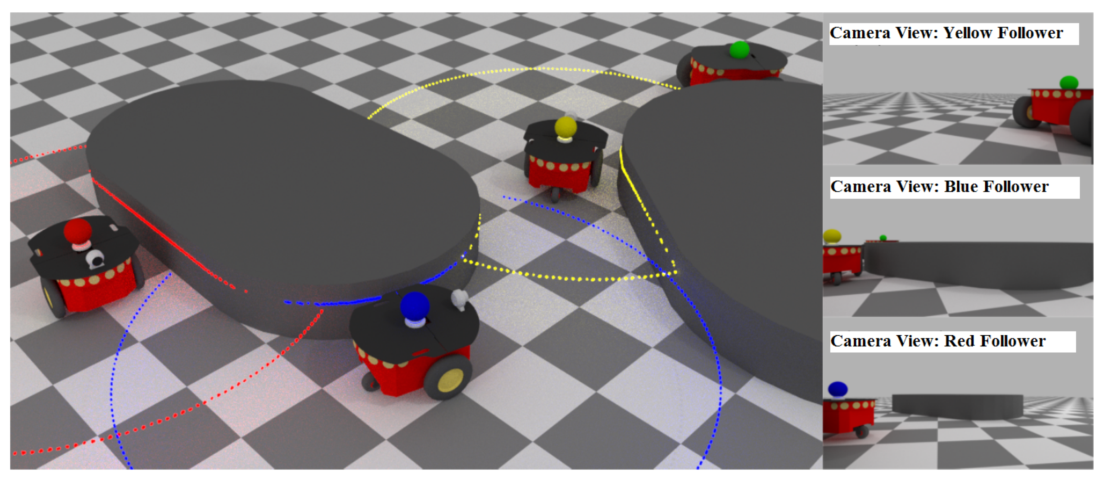
In this work, we address the problem of coordinating the motion of a platoon of multiple unicycle robots, that operate within a workspace occupied by static obstacles (see Figure 1). Each robot is equipped with proximity sensors that allow it to measure its distance with nearby obstacles and a forward looking camera with a limited field of view that allows it to detect and compute the relative position of its predecessor. Assuming that the robot that leads the platoon at the front traces a safe path inside the workplace, we propose a decentralized control law for the followers based on a modification of the prescribed performance control (PPC) [33] method, which ensures safe navigation of the entire team using only local measurements from the aforementioned on-board sensors. Additionally, the proposed control scheme guarantees a priori that visual connectivity between neighbouring/successive robots is not compromised, i.e., each robot-follower maintains its predecessor within its camera field of view and prevents occlusions introduced by the static obstacles. It should be noted that a preliminary version of the present work was accepted for presentation in [34]. Compared to [34], we have re-designed the adaptive laws for the performance functions so that we guarantee a priori visual connectivity and collision avoidance. Moreover, we present extra simulation studies for complex and realistic environments to highlight the intriguing properties of the proposed control scheme. Finally, the main contributions of our work are summarized as follows:
- Contrary to the related literature on multi-robot coordination based on sensors with limited field of view, we propose a purely decentralized control protocol with guaranteed collision avoidance and visual connectivity maintenance.
- The proposed algorithm is easy to implement since it is of low complexity and does not require any explicit inter-robot information exchange via a communication network.
1.3. Outline and Notation
The outline of this work is given as follows. In Section 2, we rigorously formulate the multi-robot coordination problem and in Section 3, we present the decentralized control law that allows safe navigation of the robot-team within the workspace while guaranteeing visual connectivity maintenance. In Section 4, we demonstrate the efficacy of the proposed control scheme via extensive simulation results and we conclude in Section 5. Finally, the following table includes a brief description of all symbols employed throughout the manuscript.
| Symbol | Description |
| Workspace | |
| i-th static obstacle | |
| Set of n obstacle indices | |
| Free space of | |
| i-th disk-shaped robot | |
| Set of robot indices | |
| Set of N follower indices | |
| Radius of i-th robot’s body | |
| Position of i-th robot | |
| Orientation of i-th robot | |
| Heading of i-th robot | |
| Commanded linear speed of i-th robot | |
| Commanded angular velocity of i-th robot | |
| Relative position of robot w.r.t. robot i | |
| Field of view of robot i | |
| Line segment (line of sight) between robots and i | |
| Distance and angle of view corresponding to robots and i | |
| Maximum allowed distance between two consecutive robots | |
| Minimum allowed distance between two consecutive robots | |
| Desired distance between two consecutive robots | |
| Half-angle of field of view sector | |
| Distance between robot i and closest obstacles on the left and right side of , respectively | |
| Distance between and closest obstacles on the left and right side of , respectively | |
| Distance and angle of view errors of robot i | |
| Performance functions bounding from below and above, respectively | |
| Performance functions bounding from below and above, respectively | |
| Convergence rate of performance functions away from obstacles | |
| Bounds on and at steady state | |
| Left and right activation terms in performance function update laws | |
| Continuous function vanishing when | |
| Transformed distance and angle of view errors | |
| Positive gains in control laws and |
2. Problem Formulation and Preliminaries
Let be a planar workspace occupied by n static obstacles with , and let denote the free space. We consider a team of disk-shaped robots of radius , for with , which operate within and whose motion obeys the unicycle kinematic model:
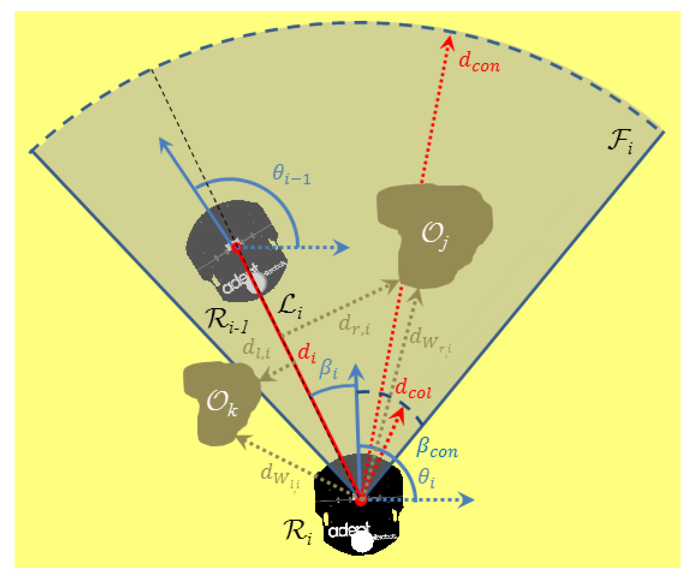
where and denote the i-th robot’s position and orientation w.r.t. an arbitrary inertial frame, respectively, denote the commanded linear and angular velocities, and . We assume that all robots other than are unable to either localize themselves within or exchange explicitly information about their state with other robots. Consequently, they have to rely on on-board sensors for obtaining information about their environment and their neighbours. Particularly, each robot follower is equipped with a forward looking camera, fixed at its center, which acquires the relative position of robot expressed in the camera’s body-fixed frame, as long as robot is visible by . Specifically, we say that robot is visible by if: (i) lies within the field of view of the camera of robot , defined as a sector of angle and radius , and (ii) the line segment connecting and does not intersect any obstacle (see Figure 2). Moreover, denotes the minimum allowable distance between robots and .
Additionally, every robot follower is equipped with proximity sensors that enable it to perceive the unoccluded outline of nearby obstacles up to distance , thus allowing it to compute the distances between itself and the closest boundary of , as well as the distances between the obstacles that are closest to the line of sight , from the left and right side, respectively (see Figure 2).
Notice that the sensing capabilities of the robots described above define a line graph that is directed and rooted at robot . Moreover, let and be respectively the distance and angle of view corresponding to robot and its predecessor , given by:
where , for all . We now formally define the problem addressed in this work.
Problem 1.
Given a feasible path to be tracked by the leading robot with bounded linear and angular velocity, design a decentralized control law for the robot followers’ velocities , such that the entire team navigates safely within the workspace while avoiding inter-robot collisions and collisions with static obstacles, i.e.,
and every preceding robot remains visible by its following robot , i.e.,
for all and . Additionally, whenever possible (owing to the aforementioned operational constraints) the formation should attain a desired inter-robot distance with zero angle of view (i.e., each follower keeps its predecessor at the center of its camera field of view at distance ).
Finally, to solve the aforementioned problem we assume that the path of the leading vehicle is feasible, in the sense that all followers may track it safely while meeting the visibility constraints, and that the initial robot configuration satisfies:
for all .
Remark 1.
It should be noted that the aforementioned assumptions are not strict since they establish the feasibility of the problem (i.e., there exists sufficient space for each robot to track the desired path and keep its predecessor visible) and that initially all robots are safe and track their predecessors, such that the proposed control scheme may be applied. Moreover, in case the robot-team is initially folded, which renders the aforementioned problem ill-defined, i.e., collision avoidance and visual connectivity cannot be met simultaneously, then an initial reordering of the line graph is needed to alleviate the deadlock. Notice that such reordering is compatible with our formulation since all following robots are considered identical with respect to sensing and actuation capabilities.
Remark 2.
In this work, we do not study the motion planning problem of the leading robot towards its goal position. Such problem has been successfully solved in the past, following either sampling-based [37,38,39] or reactive [40,41,42] approaches, under certain mild assumptions. Our scope herein is to study the leader–follower control problem under safety and visibility constraints. Thus, the aforementioned solutions can be easily adopted in our formulation to dictate the motion of the leading robot as long as the resulted path meets the feasibility assumption regarding the safety and visibility constraints.
Prescribed Performance Control Preliminaries
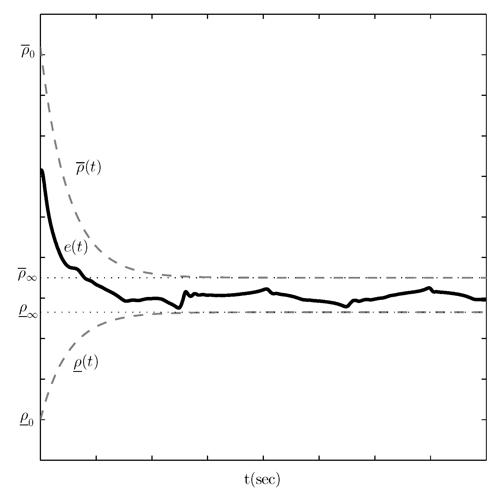
This subsection presents a summary of preliminary knowledge regarding the prescribed performance control method that will be adopted in the subsequent control design. The idea of designing controllers that guarantee prescribed transient and steady state performance specifications was originally introduced in [33]. More specifically, prescribed performance control aims at achieving convergence of a scalar tracking error to a predetermined arbitrarily small residual set with speed of convergence no less than a prespecified value, which is modeled rigorously by evolving strictly within a predefined region that is upper and lower bounded by certain functions of time, as follows:
where and denote smooth and bounded functions of time that satisfy and , called performance functions. Figure 3 illustrates the aforementioned statements for exponentially decaying performance functions, given by:
where , , , , are design parameters. In particular, the constants , are selected such that . Moreover, the parameters , represent the minimum and maximum allowable value of the steady state error and satisfy . Finally, the positive constant determines the convergence rate of and and thus is used to regulate the transient response of . Therefore, the appropriate selection of the performance functions , imposes certain transient and steady state performance characteristics on the tracking error .
The key point in prescribed performance control is a transformation of the tracking error that modulates it with respect to the corresponding transient and steady state performance specifications, encapsulated in the performance functions and . More specifically, we adopt the mapping:
Owing to the properties of the aforementioned transformation, it can be easily verified that preserving the boundedness of is sufficient to achieve prescribed performance, as described in (6).
3. Control Design
In this work, we employ the prescribed performance control (PPC) design methodology [33] in order to meet the multiple safety specifications for collision avoidance and visibility maintenance, which are critical for the operation of the multi-robot team. Hence, let us first define the distance and angle of view errors:
for each robot , . Differentiating and with respect to time and substituting (1)–(3), we obtain the following distance and angle of view error dynamics:
Notice from Figure 2 that the distance between robots and is not affected by their angular velocities, thus the two terms in (8) correspond to the projected linear velocities of robots and on their line of sight (i.e., radial direction), which dictate the rate of change of their distance. On the other hand, the rate of change of the angle of view (9) is affected by the angular velocity of robot only and the cross-radial (i.e., normal to the line of sight) velocity of the robots.
Based on the PPC approach, we shall design the velocity commands , , such that:
for appropriately selected performance functions , , and that should satisfy for all time the following properties:
Such design specifications for the distance and angle of view performance functions guarantee that each follower maintains the preceding robot within its camera field of view and avoids collisions with it. More specifically, notice that guaranteeing (10) for all time, under the properties described in (11), leads to:
and consequently, owing to (7), to:
The aforementioned formulation was adopted successfully with exponential performance functions:
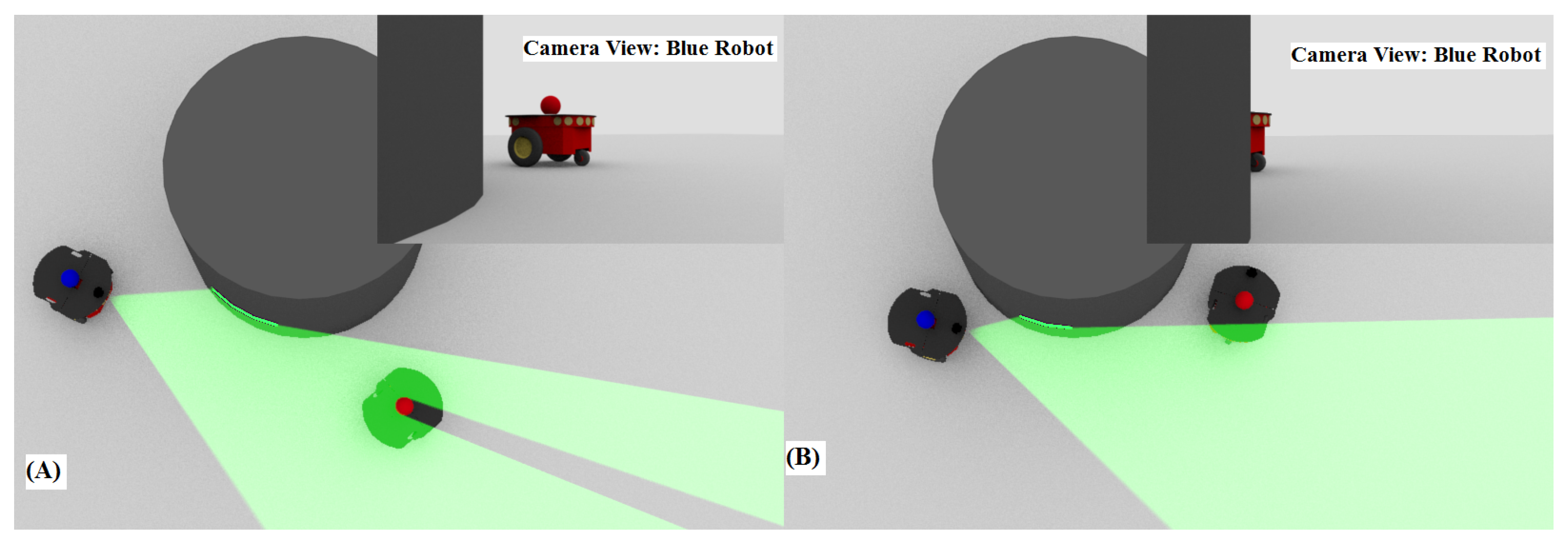
in [35] for a platoon of multiple unicycle robots operating within an obstacle-free workspace. The parameter dictates the exponential rate of convergence of the distance and angle of view errors , to small neighbourhoods of the origin with size and respectively. Notice that the properties in (11) are satisfied and hence the preceding robot is kept within the camera field of view of its follower while avoiding simultaneously collisions between them. However, it should be noted that the presence of static obstacles within the workspace complicates significantly the problem at hand since: (i) obstacles may break inter-robot visibility by raising occlusions among the robots if they stand between them, although the preceding vehicle may lie within the camera field of view of its follower, and (ii) performing an obstacle avoidance maneuver may violate visual connectivity, thus compromising the safe operation of the multi-robot team (see Figure 4). Therefore, in this work we propose to modify the control design presented in [35] by adapting the distance and angle of view performance functions , , and appropriately so that all operational specifications are met simultaneously.
In particular, when a single obstacle, either from the left or the right, depending on the motion of each pair of preceding-following robots, tends to intervene between them and raise either a visibility or collision risk (see the red robot in Figure 1), then we propose to deflect the angle of view and the distance by modifying the corresponding performance functions , , (positively or negatively respectively, but still satisfying the safety constraints) so that the line of sight moves away from the corresponding obstacle, thus ensuring that neither a collision nor a visibility break occurs. However, during the aforementioned manoeuvre to avoid an obstacle either from the left or the right, another obstacle at the opposite side may intervene (see the blue robot in Figure 1), thus introducing a conflict, since the deviation of the angle of view is not sufficient to bypass the obstacles owing to their contradicting effects on the control algorithm (i.e., the obstacle at the left of the line of sight will lead the angle of view to positive values whereas the obstacle at the right to negative values). Fortunately, in such critical case the solution to the follower’s control problem is to approach its preceding robot by reducing the distance performance functions , but keeping the inter-robot distance greater than to avoid collision. Similarly, adjusting online the inter-robot distance resolves a potential conflict when the leader performs a circular motion around its follower and an obstacle interferes between them, thus affecting their line of sight. Notice that the aforementioned strategy is viable since we have assumed that the path of the leading robot is feasible for the whole robot-team under the considered operational specifications.
Based on the aforementioned discussion, we design the following update laws for the distance and angle of view performance functions:
where and , with
for a positive constant . Notice that when the distance of the robot as well as of the line of sight with the surrounding obstacles is large (>) then both terms and vanish and consequently the aforementioned update laws yield exponential response similar to [35]. On the other hand, when a single obstacle intervenes from the left or the right between a follower and its predecessor then the term or increases, causing the distance performance functions to decrease and the angle of view performance functions to decrease or increase respectively and consequently the robot and the line of sight to move away from the obstacle. Moreover, when obstacles are close to the robot or the line of sight from both sides, then both and increase, thus decreasing the distance performance functions, so that the following robot approaches its predecessor travelling in between the obstacles. Finally, in order to ensure that the properties presented in (11) regarding the distance and angle of view performance functions , , and are met for all time, we also apply a standard Lipschitz continuous projection operator [43] on the aforementioned update laws over the sets: , , and , respectively. In particular, the adopted projection operator over a compact convex set is defined as:
where , for a positive number .
Subsequently, we present the velocity control protocol for each robot , that establishes prescribed performance with respect to the aforementioned performance functions (12) by guaranteeing the inequalities (10) for the distance and angle of view errors for all time. More specifically, we first define the transformed errors and . Notice that owing to the appropriately selected initial value of the performance functions (12) and the assumption that the robot configuration meets initially all operational specifications, the transformed errors are finite at , thus, if we manage to keep the transformed error signals and bounded for all time, via the appropriate selection of the velocity commands, then it is easy to check that we also guarantee (10) for all time, no matter how large the upper bound of and is. Consequently, the problem at hand, as described by (10), has been recast as a simple stabilization problem of the transformed error signals and , which can be resolved by the following velocity control protocol:
with positive control gains and .
Theorem 1.
Consider a team of unicycle robots that operates within a planar and obstacle cluttered environment, under the safety and visibility constraints that were described in Section 2. Moreover, assume that the leading robot of the team follows a feasible path within the workspace and that initially at all safety and visibility constraints are satisfied. The proposed decentralized control protocol (13) and (14) along with the update laws (12) that modify the performance functions navigates safely the robot team within the workspace by avoiding any collisions and visibility breaks.
Proof.
Based on the formulated problem the underlying graph of the multi-robot team comprises a directed line graph rooted to the leading vehicle . Therefore, the analysis may be broken down into pairs of preceding and following robots starting from the leading one until the last. Thus, let us define the positive definite function of the transformed errors:
Differentiating with respect to time and invoking the error dynamics (8) and (9), we get:
Hence, substituting the proposed control protocol (13) and (14), we arrive at:
Notice also that by design (owing to the projection applied on (12)) the distance and angle of view performance functions guarantee that if the corresponding errors evolve within them as dictated by (10) then and . Moreover, the terms and are strictly positive when (10) is satisfied. Finally, the velocity is bounded (i.e., for a positive upper bound ) by induction starting from the velocity of the leading robot . Consequently, becomes negative whenever and . Moreover, since the safety and visibility constraints are initially satisfied then and are well defined, from which we can easily deduce that the transformed errors and are uniformly ultimately bounded. As a result, the prescribed performance encapsulated by the inequalities (10) is satisfied for all time and thus neither collisions nor visibility breaks occur. Furthermore, all closed loop system signals, including the velocity control commands (13) and (14), remain bounded, which completes the proof. □
Remark 3.
It should be noted that the proposed control protocol (13) and (14) along with the update laws (12) employs information that is exclusively acquired by the forward looking camera and the proximity sensors that are mounted on each robot. Thus, its implementation is purely decentralized and, contrary to other works in the related literature, does not necessitate for any explicit network communication among the robots, e.g., communicating information for the velocity of the preceding robot. Moreover, notice that the operational specifications are satisfied via the appropriate modification of the performance functions (12), hence simplifying the selection of the control gains and . Nevertheless, it should be stressed that their values affect both the response of the distance and angle of view errors within the corresponding performance bounds as well as the control signal. Therefore, additional fine tuning might be needed in real robot implementation to meet the actuation constraints.
Remark 4.
The prescribed performance control technique enforces the distance and angle of view errors and to remain strictly within and respectively for all . Notice that by modulating the aforementioned errors via the logarithmic functions and , it is not difficult to verify that maintaining simply the boundedness of the modulated errors and for all is equivalent to guaranteeing (10) for all . Therefore, the problem at hand can be visualized as stabilizing the modulated errors and . A careful inspection of the proposed control scheme (13) and (14) reveals that it actually operates similarly to barrier functions in constrained optimization, admitting high negative or positive values depending on whether or and or respectively; eventually preventing and from reaching the corresponding boundaries.
4. Results
4.1. Simulation Study A
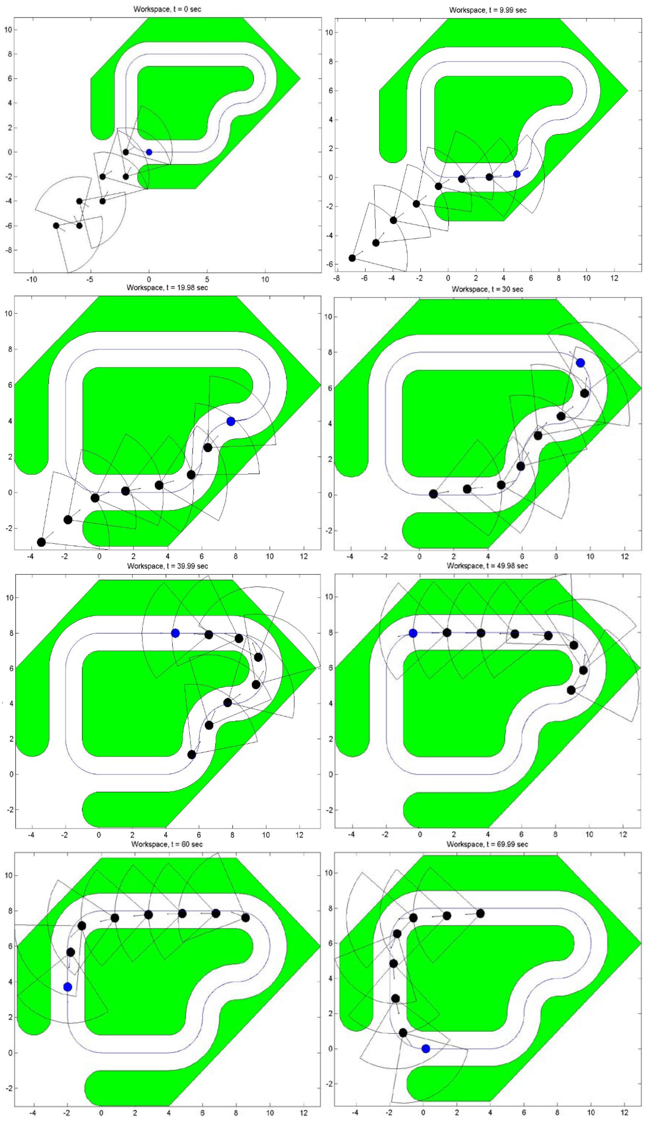
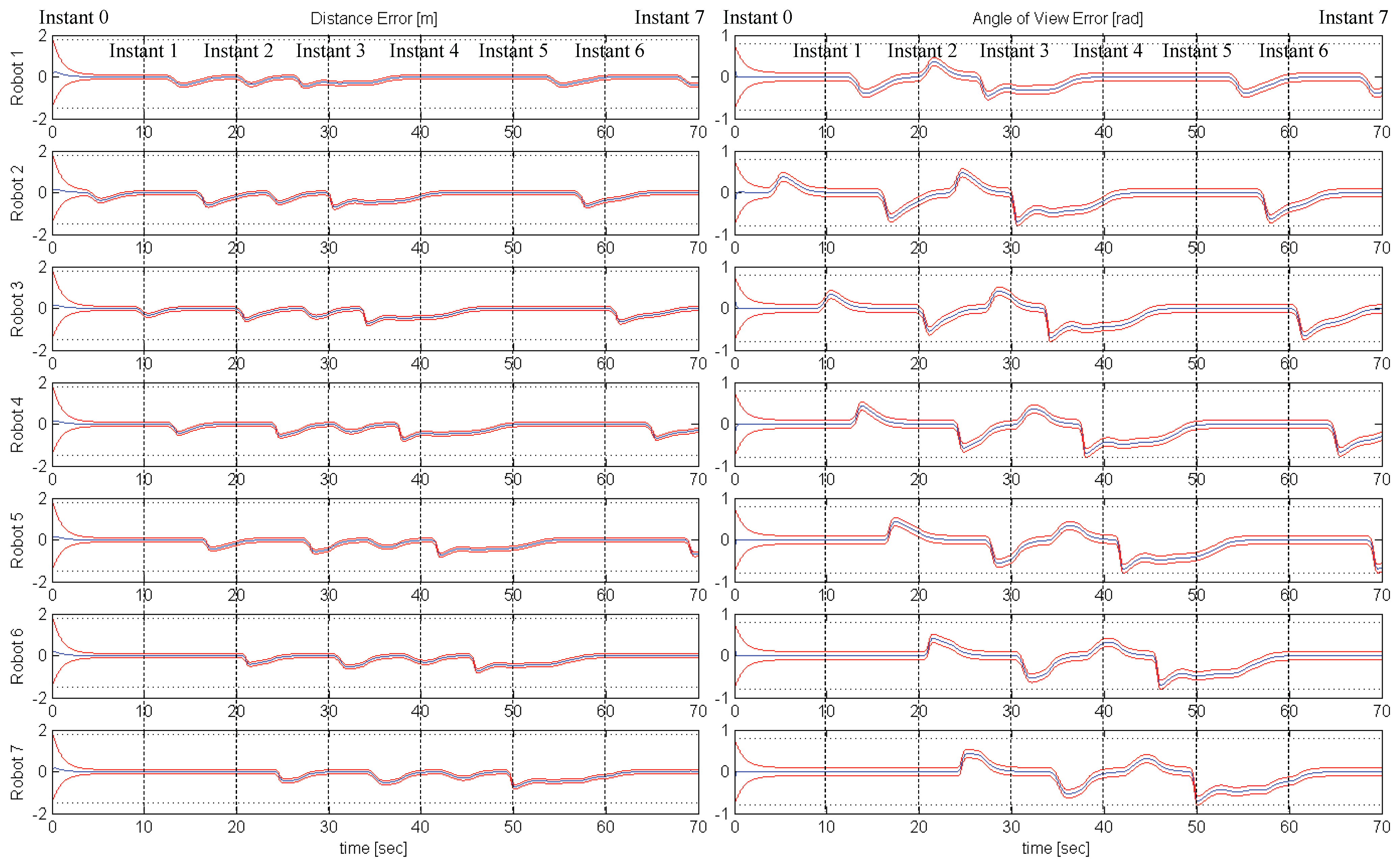
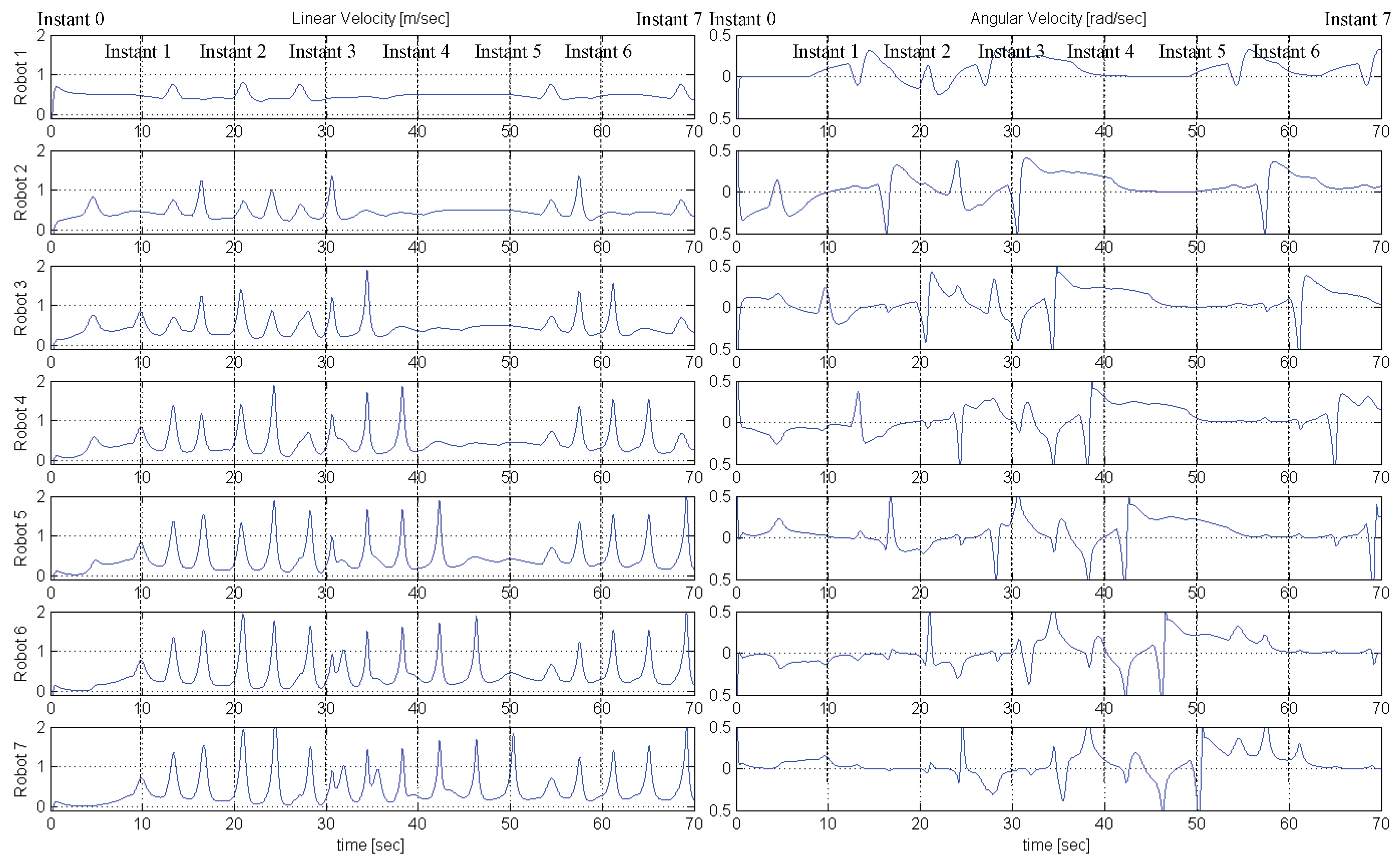
To validate the aforementioned control protocol, we first conducted a simulation study in MATLAB for a team of 7 following robots and a leading one, operating within a workspace that involves narrow passages through which the leading robot safely navigates (see Figure 5). The radius of the robots is , , the desired inter-robot distance is and the operational constraints are set as , and . Moreover, we selected the following performance function parameters , , . Finally, the parameters of the control protocol were chosen as , and . Figure 5, Figure 6 and Figure 7. More specifically, Figure 5 depicts 8 successive snapshots of the robot team within the workspace, every 10 s, along with the camera field of view of each following robot. Notice that initially at all preceding robots lie within the camera field of view of their followers and are kept within it for all time after, despite the sharp corners of the considered narrow workspace. Additionally, the evolution of the distance and angle of view errors is given in Figure 6, along with the corresponding performance functions and the operational specifications, whereas the required linear and angular velocity control commands are depicted in Figure 7. Apparently, the proposed decentralized control protocol retained the distance and angle of view errors within the performance envelope without compromising the safety of the multi-robot team (i.e., neither collisions nor visibility breaks occurred). However, notice that the linear velocity commands exhibit an oscillatory behavior while trying to meet the tight steady state performance specifications for the distance errors, whereas the angular velocity commands change quickly to steer the vehicles and avoid imminent occlusions and collisions. Nevertheless, it has to be stressed that the resulted response can be improved (as mentioned in Remark 3) by fine tuning the control gains and separately for each robot. Finally, the operation of the multi-robot teams is demonstrated by the video at the following link: https://youtu.be/yRBteQSzeVQ (accessed on 21 May 2021).
4.2. Simulation Study B
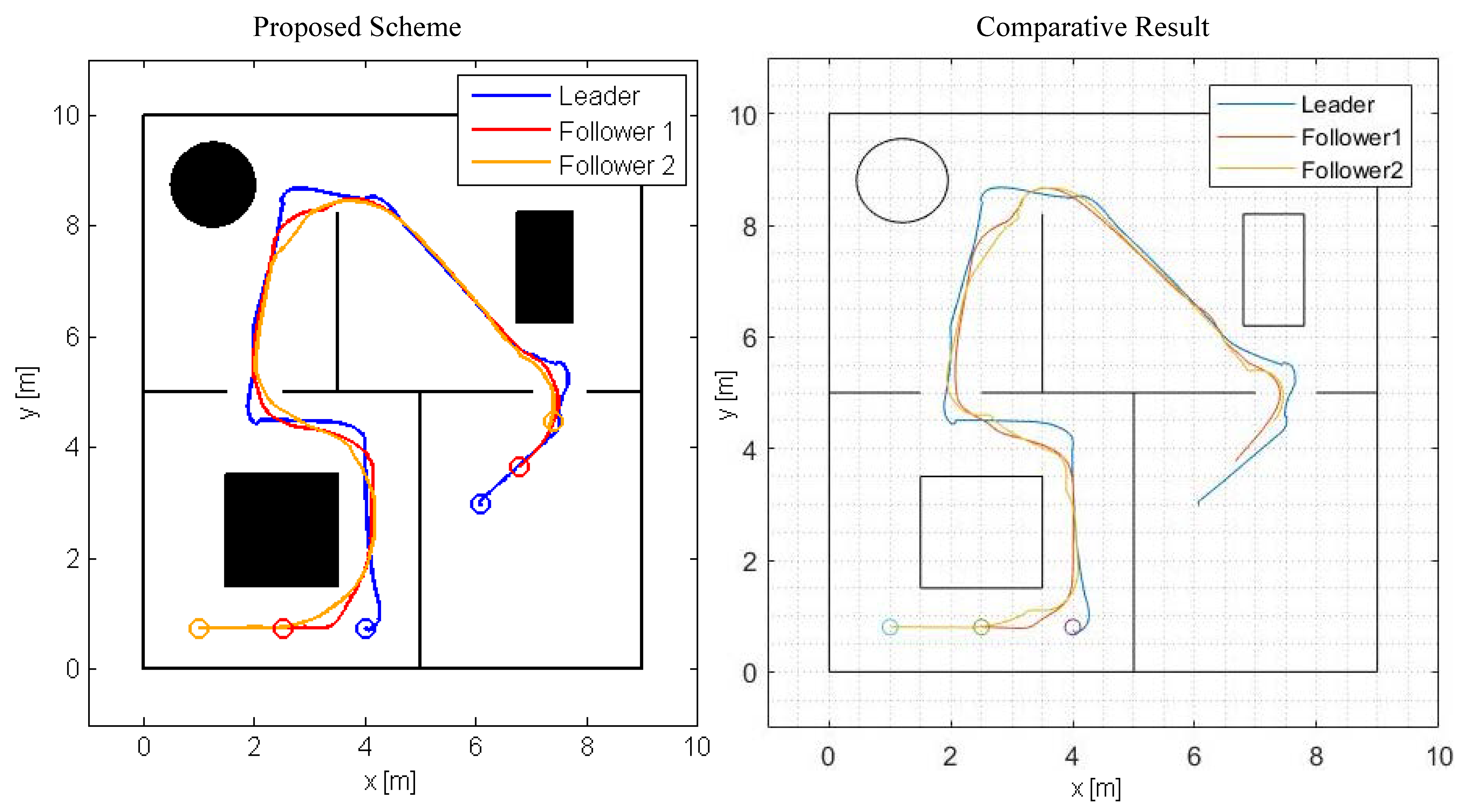
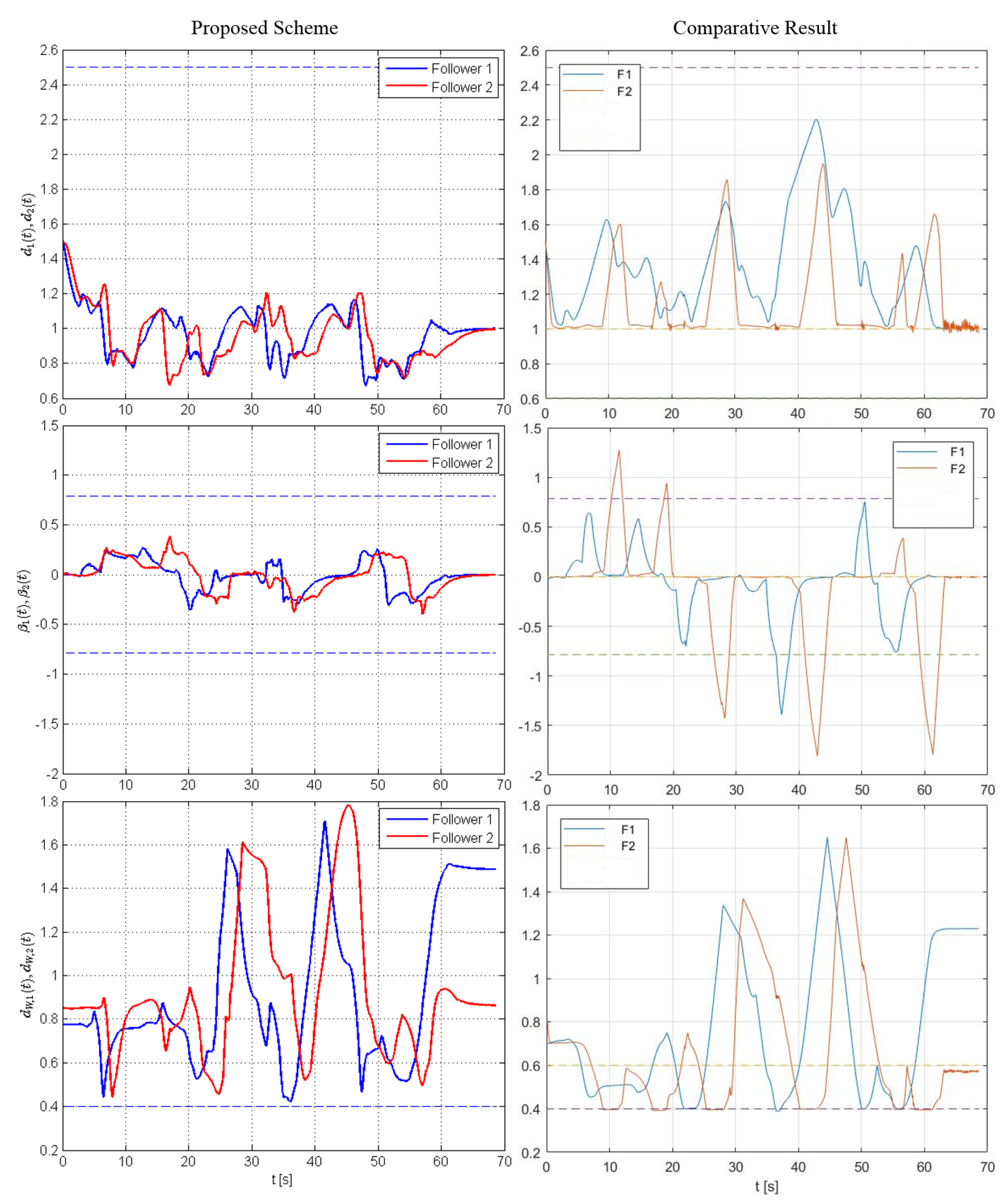
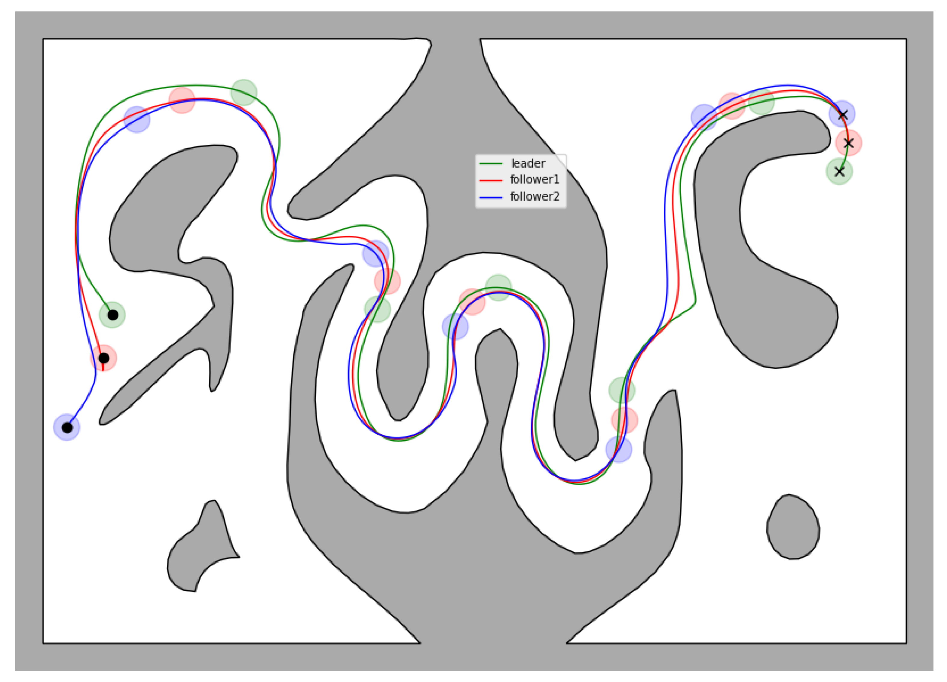
A comparative simulation study was conducted with the control scheme presented in [32] for a team of three robots, consisting of two following and a leading one, that operate within the workspace depicted in Figure 8. The simulation of the system under the control law presented in [32] was conducted in MATLAB, whereas the simulation of the system under the control scheme proposed in this work was conducted in Gazebo using ROS and Python. For the latter, appropriate models of the robots were prepared by equipping each unicycle robot with a forward-looking camera with angle-of-view 45° and range , a forward-looking proximity sensor with sensing range [−130°, 130°], and a box with 4 distinct fiducial markers placed on its sides, which were used for estimating the position of each agent’s leading robot by ArUCO [44]. The radius of the robots is , the desired inter-robot distance is and the operational constraints are set as and . Additionally, we selected the following performance function parameters . Finally, the parameters of the control protocol were chosen as and .
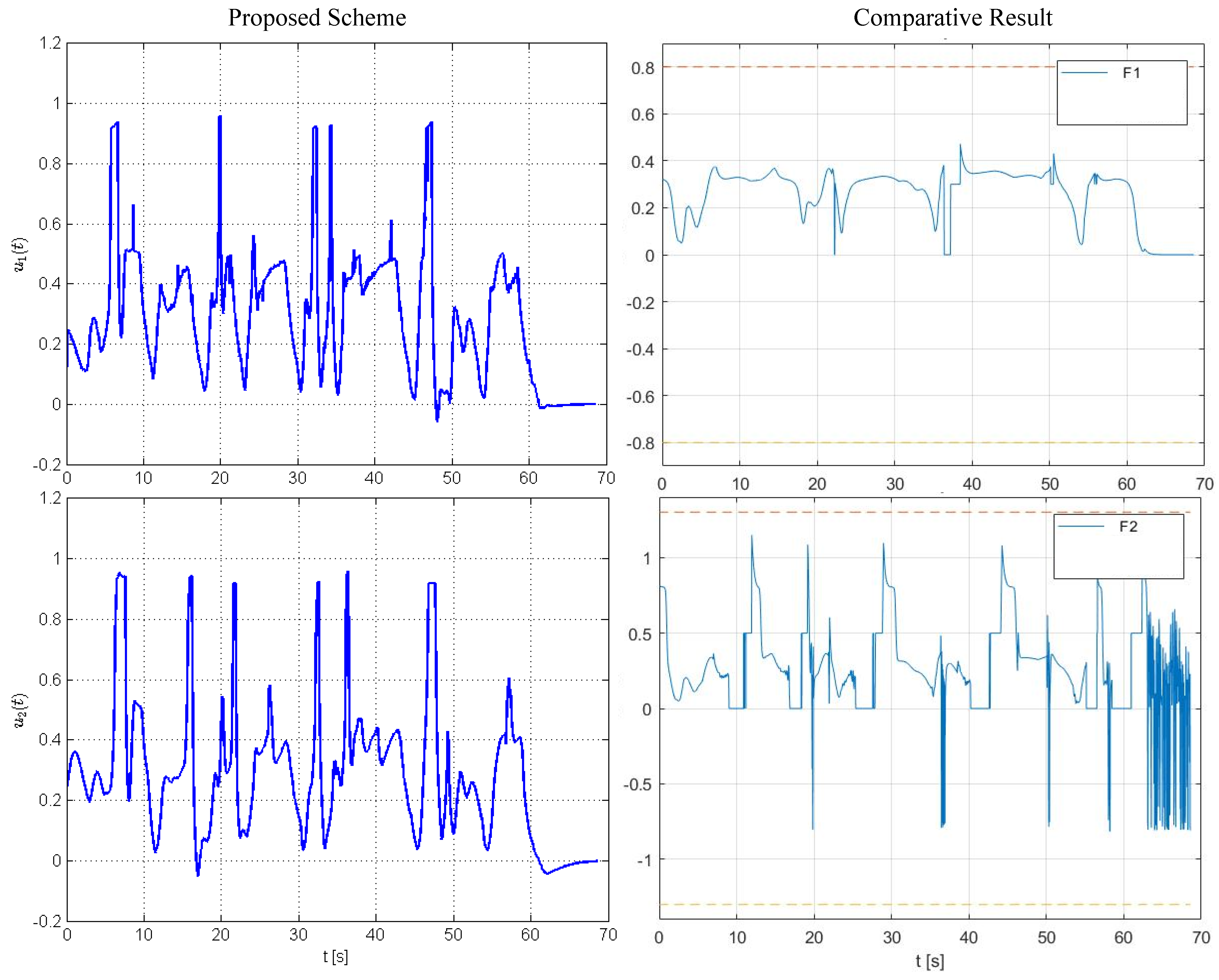
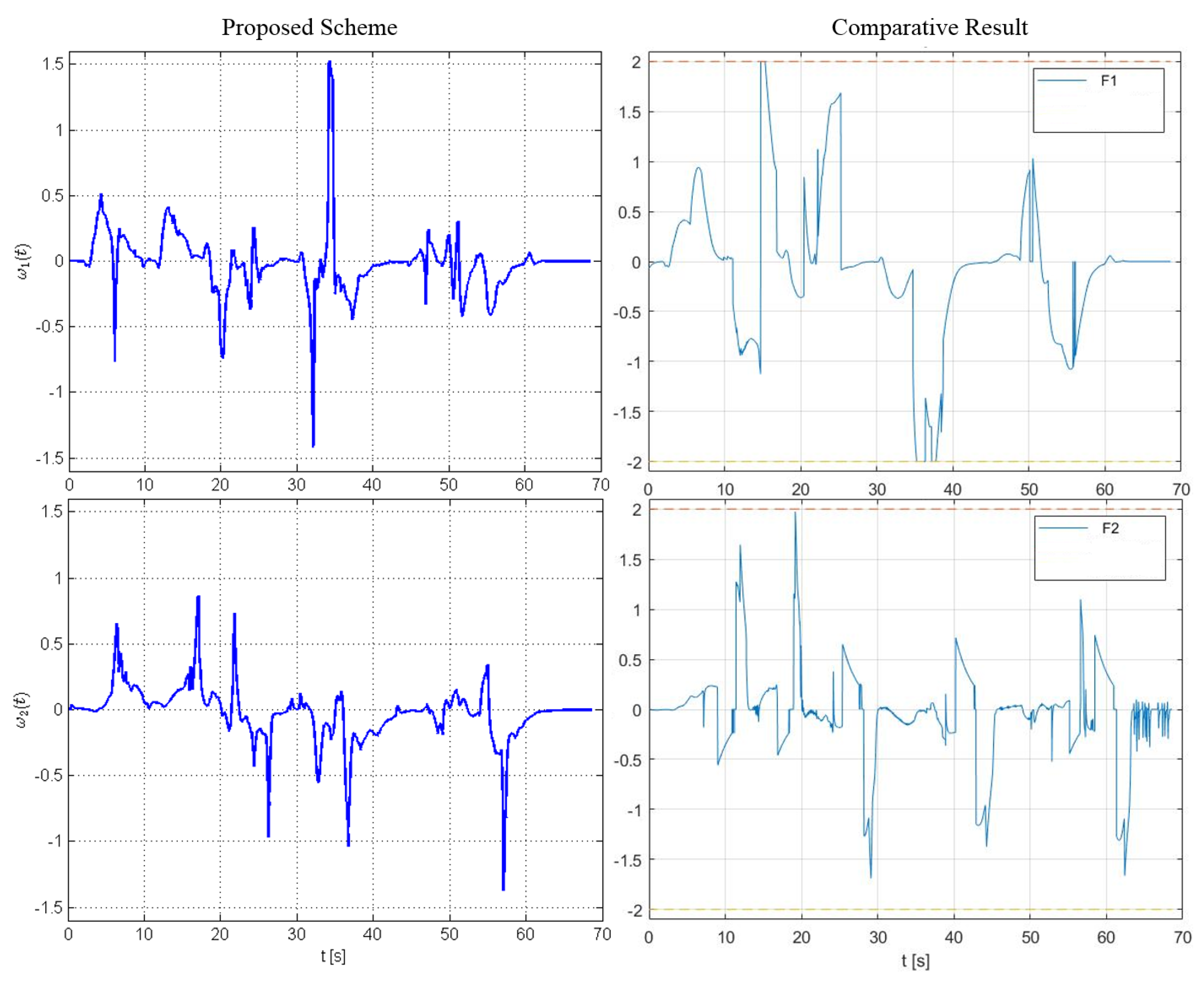
The results are given in Figure 8, Figure 9, Figure 10 and Figure 11. Particularly, Figure 8 depicts the trajectories of the robots executed using our method and the control scheme proposed in [32]. In both simulations, the team was initialized at the same configuration and the same trajectory for the leading robot was used, which was generated using the ROS Navigation Stack [45] to steer the leader towards a predefined goal configuration. The inter-robot distance between each leader–follower pair , the corresponding angle of view and the distance between each robot and the static obstacles are illustrated in Figure 9 (for safety purposes we have augmented the obstacles’ boundary by ). Apparently, the trajectories of the system under the proposed decentralized control framework satisfy all operational specifications for all time, whereas the system under the control scheme [32] violates periodically the angle-of-view constraints which, in practice, result in loss of connectivity between the agents (during such cases the algorithm presented in [32] performs a maneuver towards the position where the preceding robot was last detected assuming it will then regain visibility with it). Notice also that the range of commanded velocities as depicted in Figure 10 and Figure 11 using the proposed framework is comparable with the one generated by the control scheme presented in [32], despite the fact that our method does not impose any explicit bounds on the control inputs. Finally, the operation of the multi-robot teams under the proposed control scheme is demonstrated by the video at the following link: https://youtu.be/qvYhI_NXvKw (accessed on 21 May 2021).
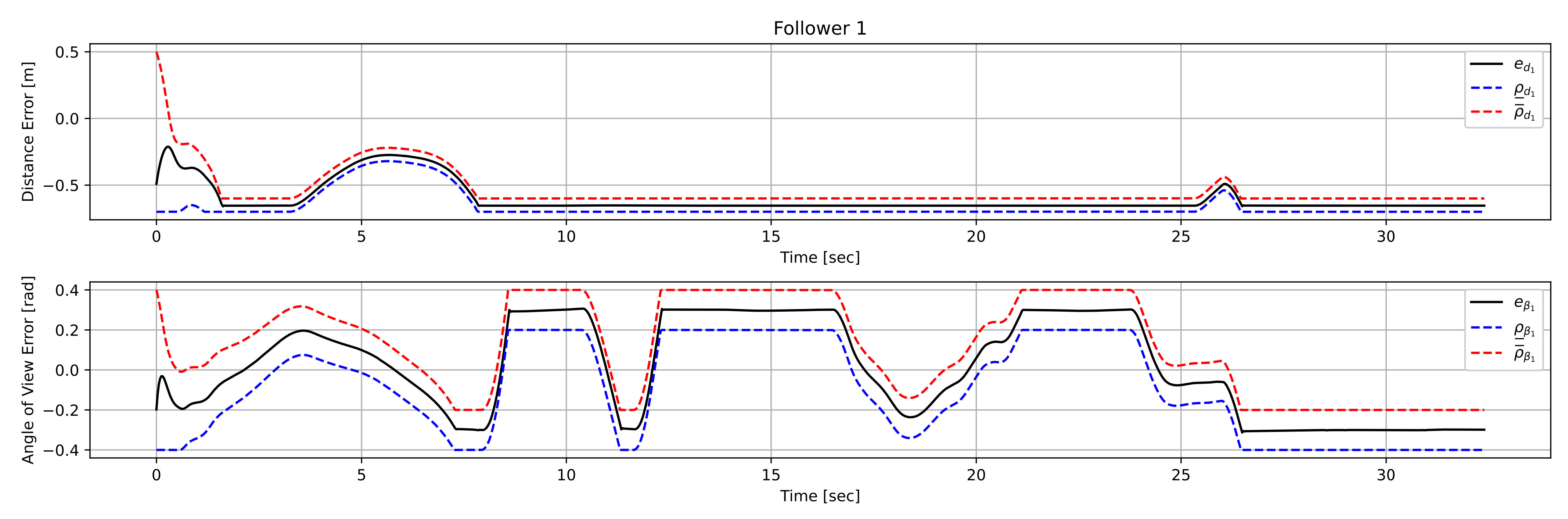
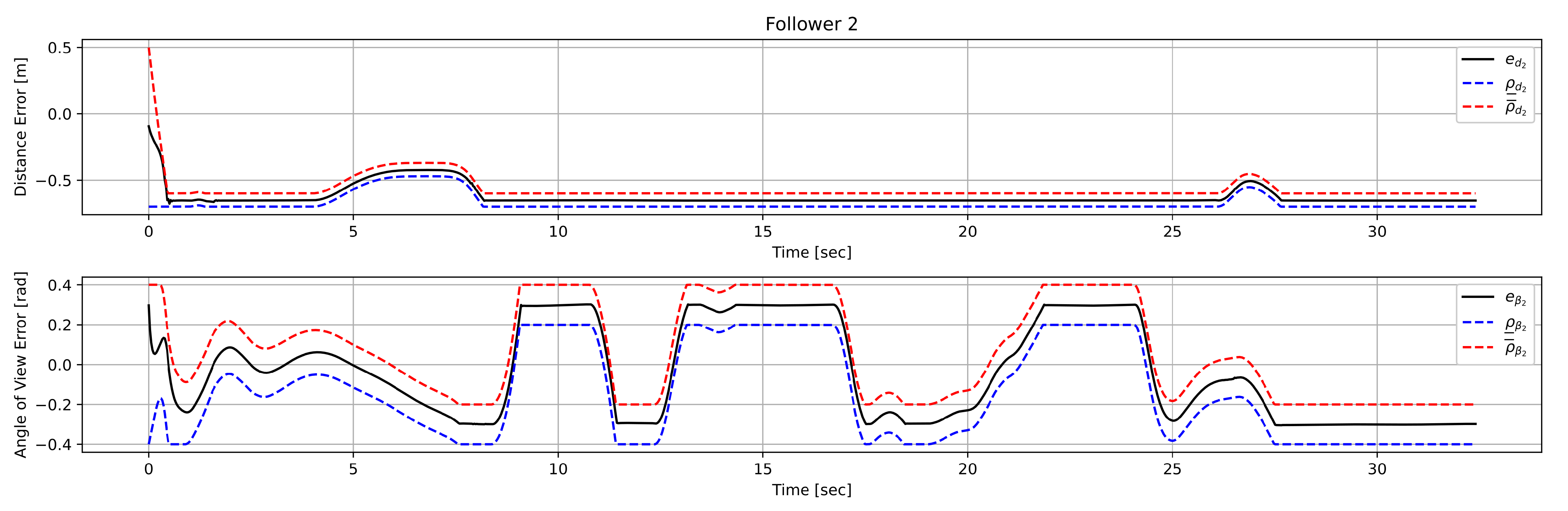
4.3. Simulation Study C
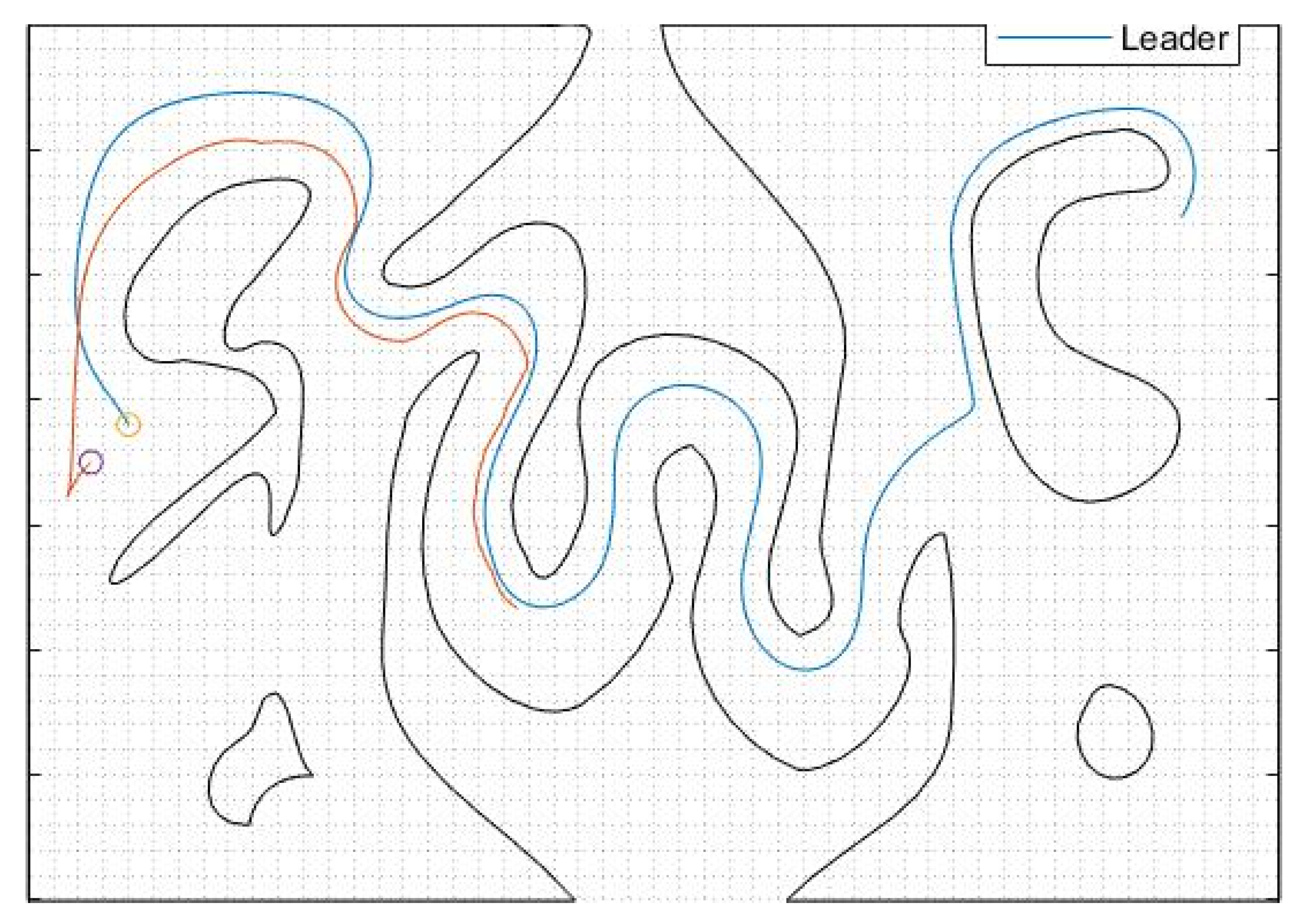
In this case study, which was also conducted in Matlab, we consider a team of 2 following robots and a leading one operating inside a complex workspace which consists of a corridor with sharp corners and arbitrarily shaped, non-convex inner obstacles. The radius of the robots is , , the desired inter-robot distance is and the operational constraints are set as , and . Moreover, we selected the following performance function parameters , , . Finally, the parameters of the control protocol were chosen as , , and . The trajectories of all three robots can be seen in Figure 12. Additionally, the distance and angle of view errors corresponding to each following robot, along with the associated performance functions, can be seen in Figure 13 and Figure 14, respectively. As we can see, the proposed control law is able to keep the errors bounded by the performance functions for all time, thus ensuring safe navigation of the entire team through the workspace and visual connectivity maintenance. Finally, it should be noted that the method proposed in [32] failed to solve the corresponding problem (even for only one follower as shown in Figure 15) since in the snaky passage, where the leader was lost at the first sharp corner, by the time the follower arrived at the position where the leader was detected for the last time the leader was no longer visible.
5. Conclusions
In this work, we tackled the problem of coordinating the motion of a platoon of unicycle robots that navigate within an obstacle-cluttered workspace. Given that each robot is equipped with proximity sensors for detecting nearby obstacles and a forward looking camera for tracking the preceding robot, we developed a safe decentralized control strategy that avoids collisions while maintaining visual connectivity between every pair of successive robots for all time. Finally, simulations results were presented that demonstrate the efficacy of the proposed control scheme.
Future research efforts will be devoted towards incorporating hard constraints on the robots’ velocity commands as well as handling moving obstacles and other more complex graph configurations to increase the applicability of our approach. Moreover, we plan to verify the theoretical findings via experimental results, employing real unicycle robotic vehicles. Towards this direction, we also intend to deal with the problems of intermittent (or loss of) visual tracking, owing to environmental interference (e.g., light conditions or shading) and motion blurring, as well as of actuation (either total or partial) failure.
Author Contributions
Conceptualization, C.P.B., P.V. and K.J.K.; methodology, C.P.B.; software, C.P.B. and P.V.; validation, C.P.B. and P.V.; formal analysis, C.P.B.; writing—original draft preparation, C.P.B.; writing—review and editing, P.V. and K.J.K.; supervision, K.J.K. All authors have read and agreed to the published version of the manuscript.
Funding
This work was carried out/funded in the context of the project “Coordination of Multiple Robotic Vehicles in Obstacle-Cluttered Environments” (MIS 5049094) under the call for proposals “Researchers’ support with an emphasis on young researchers—2nd Cycle”. The project is co-financed by Greece and the European Union (European Social Fund—ESF) by the Operational Programme Human Resources Development, Education and Lifelong Learning 2014–2020.
Institutional Review Board Statement
Not applicable.
Informed Consent Statement
Not applicable.
Data Availability Statement
Not applicable.
Acknowledgments
The authors would like to thank Katerina Gratsia, a senior student of School of Mechanical Engineering at National Technical University of Athens, for providing the comparative simulation results included in Section 4.2 and Section 4.3.
Conflicts of Interest
The authors declare no conflict of interest.
References
- Jadbabaie, A.; Lin, J.; Morse, A.S. Coordination of groups of mobile autonomous agents using nearest neighbor rules. IEEE Trans. Autom. Control 2003, 48, 988–1001. [Google Scholar] [CrossRef] [Green Version]
- Fax, J.A.; Murray, R.M. Information flow and cooperative control of vehicle formations. IEEE Trans. Autom. Control 2004, 49, 1465–1476. [Google Scholar] [CrossRef] [Green Version]
- Desai, J.P.; Ostrowski, J.P.; Kumar, V. Modeling and control of formations of nonholonomic mobile robots. IEEE Trans. Robot. Autom. 2001, 17, 905–908. [Google Scholar] [CrossRef] [Green Version]
- Das, A.K.; Fierro, R.; Kumar, V.; Ostrowski, J.P.; Spletzer, J.; Taylor, C.J. A vision-based formation control framework. IEEE Trans. Robot. Autom. 2002, 18, 813–825. [Google Scholar] [CrossRef] [Green Version]
- Cowan, N.; Shakernia, O.; Vidal, R.; Sastry, S. Vision-based follow the leader. In Proceedings of the IEEE/RSJ International Conference on Intelligent Robots and Systems, Las Vegas, NV, USA, 27–31 October 2003; pp. 1796–1801. [Google Scholar]
- Mariottini, G.L.; Morbidi, F.; Prattichizzo, D.; Pappas, G.J.; Daniilidis, K. leader–follower formations: Uncalibrated vision-based localization and control. In Proceedings of the IEEE International Conference on Robotics and Automation, Roma, Italy, 10–14 April 2007; pp. 2403–2408. [Google Scholar]
- Mariottini, G.L.; Morbidi, F.; Prattichizzo, D.; Valk, N.V.; Pappas, G.; Daniilidis, K. Vision-based localization for leader–follower formation control. IEEE Trans. Robot. 2009, 25, 1431–1438. [Google Scholar] [CrossRef]
- OOrqueda, A.; Fierro, R. Robust vision-based nonlinear formation control. In Proceedings of the IEEE American Control Conference, Minneapolis, MN, USA, 14–16 June 2006; pp. 1422–1427. [Google Scholar]
- Kannan, H.; Chitrakaran, V.K.; Dawson, D.M.; Burg, T. Vision based leader/follower tracking for nonholonomic mobile robots. In Proceedings of the IEEE American Control Conference, New York, NY, USA, 9–13 July 2007; pp. 2159–2164. [Google Scholar]
- Min, H.J.; Drenner, A.; Papanikolopoulos, N. Vision-based leader follower formations with limited information. In Proceedings of the IEEE International Conference on Robotics and Automation, Kobe, Japan, 12–17 May 2009; pp. 351–356. [Google Scholar]
- Kantor, G.; Rizzi, A.A. Feedback control of underactuated systems via sequential composition: Visually guided control of a unicycle. In Robotics Research; Dario, P., Chatila, R., Eds.; Springer: Berlin/Heidelberg, Germany, 2005; pp. 281–290. [Google Scholar]
- Lopes, G.A.D.; Koditschek, D.E. Visual servoing for nonholonomically constrained three degree of freedom kinematic systems. Int. J. Robot. Res. 2007, 26, 715–736. [Google Scholar] [CrossRef]
- Bhattacharya, S.; Murrieta-Cid, R.; Hutchinson, S. Optimal paths for landmark-based navigation by differential-drive vehicles with field of- view constraints. IEEE Trans. Robot. 2007, 23, 47–59. [Google Scholar] [CrossRef] [Green Version]
- Salaris, P.; Fontanelli, D.; Pallottino, L.; Bicchi, A. Shortest paths for a robot with nonholonomic and field-of view constraints. IEEE Trans. Robot. 2010, 26, 269–280. [Google Scholar] [CrossRef]
- Maniatopoulos, S.; Panagou, D.; Kyriakopoulos, K.J. Model predictive control for the navigation of a nonholonomic vehicle with field- of-view constraints. In Proceedings of the IEEE American Control Conference, Washington, DC, USA, 17–19 June 2013; pp. 3967–3972. [Google Scholar]
- Lin, J.; Miao, Z.; Zhong, H.; Peng, W.; Wang, Y.; Fierro, R. Adaptive Image-Based leader–follower Formation Control of Mobile Robots with Visibility Constraints. IEEE Trans. Ind. Electron. 2020, 68, 6010–6019. [Google Scholar] [CrossRef]
- Liang, X.; Wang, H.; Liu, Y.-H.; Chen, W.; Liu, T. Formation Control of Nonholonomic Mobile Robots without Position and Velocity Measurements. IEEE Trans. Robot. 2018, 34, 434–446. [Google Scholar] [CrossRef]
- Wang, H.; Guo, D.; Liang, X.; Chen, W.; Hu, G.; Leang, K.K. Adaptive Vision-Based Leader–Follower Formation Control of Mobile Robots. IEEE Trans. Ind. Electron. 2017, 64, 2893–2902. [Google Scholar] [CrossRef]
- Liang, X.; Liu, Y.-H.; Wang, H.; Chen, W.; Xing, K.; Liu, T. Leader-Following Formation Tracking Control of Mobile Robots without Direct Position Measurements. IEEE Trans. Autom. Control 2016, 61, 4131–4137. [Google Scholar] [CrossRef]
- Brinon-Arranz, L.; Seuret, A.; Canudas-de-Wit, C. Cooperative Control Design for Time-Varying Formations of Multi-Agent Systems. IEEE Trans. Automat. Control 2014, 59, 2283–2288. [Google Scholar] [CrossRef] [Green Version]
- Morbidi, F.; Bullo, F.; Prattichizzo, D. Visibility maintenance via controlled invariance for leader–follower vehicle formations. Automatica 2011, 47, 1060–1067. [Google Scholar] [CrossRef] [Green Version]
- Murrieta-Cid, R.; Ruiz, U.; Marroquin, J.L.; Laumond, J.-P.; Hutchinson, S. Tracking an omnidirectional evader with a differential drive robot. Auton. Robot. 2011, 18, 345–366. [Google Scholar] [CrossRef]
- Ruiz, U.; Murrieta-Cid, R. A homicidal differential drive robot. In Proceedings of the IEEE International Conference on Robotics and Automation, Saint Paul, MN, USA, 14–18 May 2012; pp. 3218–3225. [Google Scholar]
- LaValle, S.M.; Gonzalez-Banos, H.H.; Becker, C.; Latombe, J.-C. Motion strategies for maintaining visibility of a moving target. In Proceedings of the IEEE International Conference on Robotics and Automation, Albuquerque, NM, USA, 20–25 April 1997; pp. 731–736. [Google Scholar]
- Murrieta-Cid, R.; Munoz-Gomez, L.; Alencastre-Miranda, M.; Sarmiento, A.; Kloder, S.; Hutchinson, S.; Lamiraux, F.; Laumond, J.P. Maintaining visibility of a moving holonomic target at a fixed distance with a non-holonomic robot. In Proceedings of the IEEE/RSJ International Conference on Intelligent Robots and Systems, Edmonton, AB, Canada, 2–6 August 2005; pp. 2687–2693. [Google Scholar]
- Murrieta-Cid, R.; Monroy, R.; Hutchinson, S.; Laumond, J.-P. A complexity result for the pursuit-evasion game of maintaining visibility of a moving evader. In Proceedings of the IEEE International Conference on Robotics and Automation, Pasadena, CA, USA, 19–23 May 2008; pp. 2657–2664. [Google Scholar]
- Murrieta-Cid, R.; Muppirala, T.; Sarmiento, A.; Bhattacharya, S.; Hutchinson, S. Surveillance strategies for a pursuer with finite sensor range. Int. J. Robot. Res. 2007, 26, 233–253. [Google Scholar] [CrossRef] [Green Version]
- Xu, Y.; Wang, C.; Cai, X.; Li, Y.; Xu, L. Output-feedback formation tracking control of networked nonholonomic multi-robots with connectivity preservation and collision avoidance. Neurocomputing 2020, 414, 267–277. [Google Scholar] [CrossRef]
- Ge, S.S.; Liu, X.; Goh, C.-H.; Xu, L. Formation Tracking Control of Multiagents in Constrained Space. IEEE Trans. Control Syst. Technol. 2016, 24, 992–1003. [Google Scholar] [CrossRef]
- Panagou, D.; Kumar, V. Cooperative visibility maintenance for leader–follower formations in obstacle environments. IEEE Trans. Robot. 2014, 30, 831–844. [Google Scholar] [CrossRef]
- Sakai, D.; Fukushima, H.; Matsuno, F. leader–follower Navigation in Obstacle Environments while Preserving Connectivity without Data Transmission. IEEE Trans. Control Syst. Technol. 2018, 26, 1233–1248. [Google Scholar] [CrossRef] [Green Version]
- Wang, Y.; Wang, D.; Yang, S.; Shan, M. A Practical Leader–Follower Tracking Control Scheme for Multiple Nonholonomic Mobile Robots in Unknown Obstacle Environments. IEEE Trans. Control Syst. Technol. 2019, 27, 1685–1693. [Google Scholar] [CrossRef]
- Bechlioulis, C.P.; Rovithakis, G.A. Robust adaptive control of feedback linearizable mimo nonlinear systems with prescribed Performance. IEEE Trans. Autom. Control 2008, 53, 2090–2099. [Google Scholar] [CrossRef]
- Bechlioulis, C.P.; Vlantis, P.; Kyriakopoulos, K.J. Motion Coordination of Multiple Unicycle Robotic Vehicles under Operational Constraints in Obstacle-Cluttered Workspaces. In Proceedings of the Mediterranean Conference on Control and Automation, Virtual, 22–25 June 2021. [Google Scholar]
- Verginis, C.K.; Bechlioulis, C.P.; Dimarogonas, D.V.; Kyriakopoulos, K.J. Decentralized 2-D control of vehicular platoons under limited visual feedback. In Proceedings of the IEEE/RSJ International Conference on Intelligent Robots and Systems, Hamburg, Germany, 28 September–2 October 2015; pp. 3566–3570. [Google Scholar]
- Delimpaltadakis, I.; Bechlioulis, C.P.; Kyriakopoulos, K.J. Decentralized Platooning with Obstacle Avoidance for Car-like Vehicles with Limited Sensing. IEEE Robot. Autom. Lett. 2018, 3, 835–840. [Google Scholar] [CrossRef]
- Stentz, A. Optimal and Efficient Path Planning for Partially-Known Environments. In Proceedings of the International Conference on Robotics and Automation, San Diego, CA, USA, 8–13 May 1994; pp. 3310–3317. [Google Scholar]
- Karaman, S.; Frazzoli, E. Sampling-based algorithms for optimal motion planning. Int. J. Robot. Res. 2011, 30, 846–894. [Google Scholar] [CrossRef]
- Kingston, Z.; Moll, M.; Kavraki, L.E. Sampling-based methods for motion planning with constraints. Annu. Rev. Control Robot. Auton. Syst. 2018, 1, 159–185. [Google Scholar] [CrossRef] [Green Version]
- Rimon, E.; Koditschek, D.E. Exact robot navigation using artificial potential functions. IEEE Trans. Robot. Autom. 1992, 8, 501–518. [Google Scholar] [CrossRef] [Green Version]
- Kim, J.O.; Khosla, P.K. Real-time obstacle avoidance using harmonic potential functions. IEEE Trans. Robot. Autom. 1992, 8, 338–349. [Google Scholar] [CrossRef] [Green Version]
- Vlantis, P.; Vrohidis, C.; Bechlioulis, C.; Kyriakopoulos, K. Robot navigation in complex workspaces using harmonic maps. In Proceedings of the IEEE International Conference on Robotics and Automation, Brisbane, Australia, 21–25 May 2018; pp. 1726–1731. [Google Scholar]
- Cai, Z.; de Queiroz, M.; Dawson, D. A sufficiently smooth projection operator. IEEE Trans. Autom. Control 2006, 51, 135–139. [Google Scholar] [CrossRef]
- Garrido-Jurado, S.; Muñoz-Salinas, R.; Madrid-Cuevas, F.J.; Marín-Jiménez, M.J. Automatic generation and detection of highly reliable fiducial markers under occlusion. Pattern Recognit. 2014, 47, 2280–2292. [Google Scholar] [CrossRef]
- Available online: https://wiki.ros.org/navigation (accessed on 21 May 2021).
Figure 1.
A platoon of 4 unicycle robots equipped with forward looking cameras and LiDAR sensors.

Figure 2.
Robot tracking its predecessor .

Figure 3.
Graphical illustration of prescribed performance control for exponential performance functions and .
Figure 3.
Graphical illustration of prescribed performance control for exponential performance functions and .

Figure 4.
The obstacle creates a visual occlusion.

Figure 5.
Study A: The operation of the robot-team (blue color indicates the leading robot and black the following ones) is depicted for 8 consecutive time instants, every 10 s. Each camera field of view is given by the black quadrants.
Figure 5.
Study A: The operation of the robot-team (blue color indicates the leading robot and black the following ones) is depicted for 8 consecutive time instants, every 10 s. Each camera field of view is given by the black quadrants.

Figure 6.
Study A: The evolution of the distance and angle of view errors (blue solid lines) along with the corresponding performance functions (red solid lines) and safety constraints (black dashed lines).
Figure 6.
Study A: The evolution of the distance and angle of view errors (blue solid lines) along with the corresponding performance functions (red solid lines) and safety constraints (black dashed lines).

Figure 7.
Study A: The evolution of the linear and angular velocity commands.

Figure 8.
Study B: The trace of the robots within the workspace.

Figure 9.
Study B: The evolution of the inter-robot distance and angle of view as well as the distance to the workspace boundary, along with the corresponding safety constraints (dashed lines).
Figure 9.
Study B: The evolution of the inter-robot distance and angle of view as well as the distance to the workspace boundary, along with the corresponding safety constraints (dashed lines).

Figure 10.
Study B: The evolution of the linear velocity commands.

Figure 11.
Study B: The evolution of the angular velocity commands.

Figure 12.
Study C: The trace of the robots within the workspace, along with the configuration of the team at several time instances.
Figure 12.
Study C: The trace of the robots within the workspace, along with the configuration of the team at several time instances.

Figure 13.
Study C: Distance and angle of view errors of robot .

Figure 14.
Study C: Distance and angle of view errors of robot .

Figure 15.
Study C: The trace of the leader and robot following the control scheme presented in [32].
Figure 15.
Study C: The trace of the leader and robot following the control scheme presented in [32].

Publisher’s Note: MDPI stays neutral with regard to jurisdictional claims in published maps and institutional affiliations. |
© 2021 by the authors. Licensee MDPI, Basel, Switzerland. This article is an open access article distributed under the terms and conditions of the Creative Commons Attribution (CC BY) license (https://creativecommons.org/licenses/by/4.0/).
Share and Cite
MDPI and ACS Style
Bechlioulis, C.P.; Vlantis, P.; Kyriakopoulos, K.J. Coordination of Multiple Robotic Vehicles in Obstacle-Cluttered Environments. Robotics 2021, 10, 75. https://doi.org/10.3390/robotics10020075
AMA Style
Bechlioulis CP, Vlantis P, Kyriakopoulos KJ. Coordination of Multiple Robotic Vehicles in Obstacle-Cluttered Environments. Robotics. 2021; 10(2):75. https://doi.org/10.3390/robotics10020075
Chicago/Turabian StyleBechlioulis, Charalampos P., Panagiotis Vlantis, and Kostas J. Kyriakopoulos. 2021. "Coordination of Multiple Robotic Vehicles in Obstacle-Cluttered Environments" Robotics 10, no. 2: 75. https://doi.org/10.3390/robotics10020075
Note that from the first issue of 2016, this journal uses article numbers instead of page numbers. See further details here.