Making Light Work of Metal Bending: Laser Forming in Rapid Prototyping


1
Fellowship Program at US Army Research Laboratory, Oak Ridge Associated Universities (ORAU), Adelphi, MD 20783, USA
2
Department of Chemical and Biomolecular Engineering, North Carolina State University, Raleigh, NC 27603, USA
3
Sensors and Electron Devices Directorate, US Army Research Laboratory, Adelphi, MD 20783, USA
*
Author to whom correspondence should be addressed.
Quantum Beam Sci. 2020, 4(4), 44; https://doi.org/10.3390/qubs4040044
Submission received: 18 November 2020
/
Revised: 10 December 2020
/
Accepted: 10 December 2020
/
Published: 14 December 2020
(This article belongs to the Special Issue Laser Assisted Manufacturing)
Abstract
:Lasers can be used to bend 2D metal sheets into complex 3D objects in a process called ‘laser forming.’ Laser forming bends metal sheets by locally heating the sheets to generate plastic strains and is an established metal bending technology in the shipbuilding industry. Recent studies have investigated the laser forming of thin metal parts as a complementary rapid prototyping technology to metal 3D printing. This review discusses the laser forming process, beginning with the mechanisms before covering various design considerations. Laser forming for the rapid manufacturing of metal parts is then reviewed, including the recent advances in process planning, before highlighting promising future research directions.
1. Introduction
Fabricating complex 3D structures is a difficult task, as many materials and processes are inherently 2D. Flat structures need to be carefully assembled to produce the desired 3D shape, whether a ship, an automobile, or a solar array. One of the oldest ways to produce 3D structures from flat objects is origami, the Japanese art of paper folding [1,2]. Origami principles can apply to other sheets of material, often with the goal of assembling the final 3D structure far from the point of production of the 2D pattern [3,4,5].
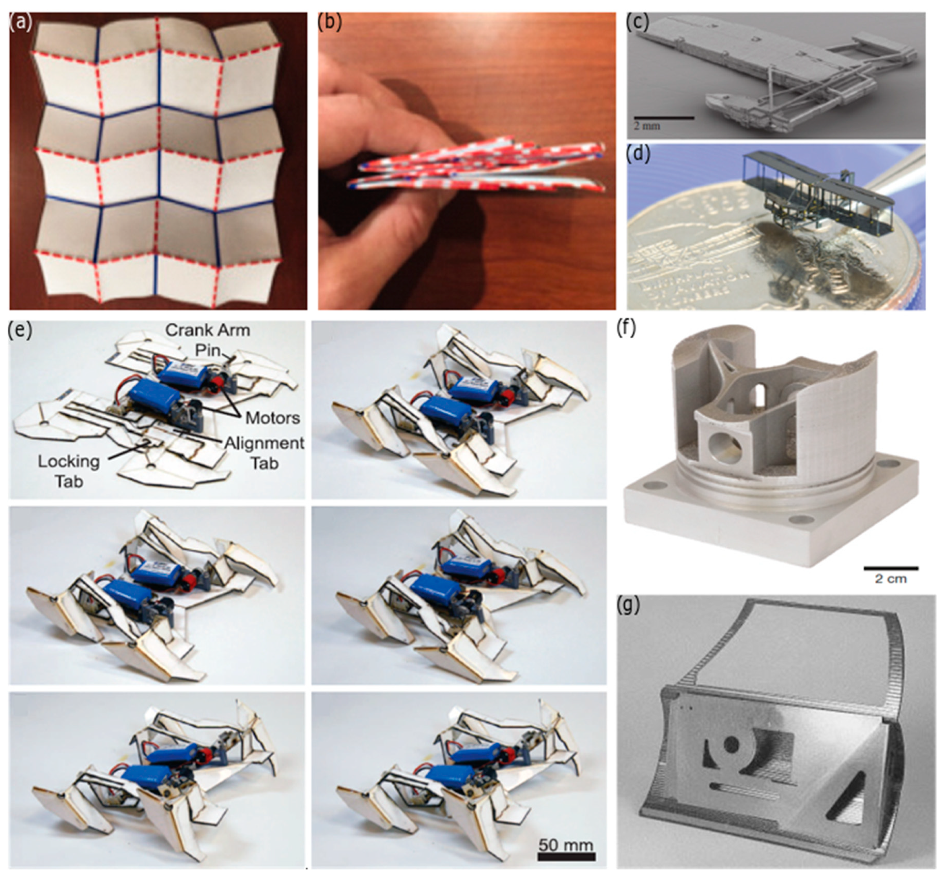
Researchers have developed algorithms to achieve complex 3D shapes from 2D fold patterns [6]. These algorithms are not limited to paper, although the algorithms typically neglect the effect of substrate thickness and, thus, work best on materials that are thin and inextensible, like paper. Oftentimes, the desired structures need to be made of materials that have a non-negligible thickness [7,8]. Folding rigid materials is typically done by attaching rigid facets with compliant hinges [9], but this places restrictions on what can be produced, a term called rigid foldability [10]. One of the most common rigid folding patterns is the Miura-ora pattern (Figure 1a,b), as it allows large area structures to be compactly stored before deployment, which is valuable for space applications [5,7,11,12]. In many applications, actuation (folding) is done manually (Figure 1c,d) [13]; however, researchers are exploring ways to create hinges that fold in response to external stimuli (e.g., light, electricity, heat, moisture), allowing for self-folding (Figure 1e) [3,14,15,16,17].
Origami manufacturing using computational design algorithms is a relatively new method for rapid prototyping. Rapid prototyping is defined as the direct translation of computer aided design (CAD) files into 3D objects, with 3D printing the most common approach [18]. Three-dimensional printing is a popular technology that additively builds objects through the layered deposition of material [19,20]. 3D printing allows highly customized metal parts to be fabricated with minimal waste (Figure 1f), making it an attractive technology for ‘mass customization’ [21]. Many metal 3D printing methods use a focused energy beam (laser or electron beam) to fuse metal powders together, building the part layer by layer, but the process is long and has a limited build volume [20,22,23] and metal 3D printers are also relatively expensive (to the order of hundreds of thousands of dollars for a commercial printer) [23]. The unfused powder acts a support, allowing pieces to be built with moderate overhangs, but sharp bends remain challenging [23], as well as thin shells [24]. Origami folding, which allows rapid and cheap creation of 3D shells of material, is therefore an important complementary technology, well-suited for many devices, such as antennas, waveguides, and other systems that rely on thin layers of metal. Thin metal sheets are easy to bend, and overhangs can be generated with almost any degree of bend angle, enabling the production of complex shapes with simple folds and cuts (Figure 1g).
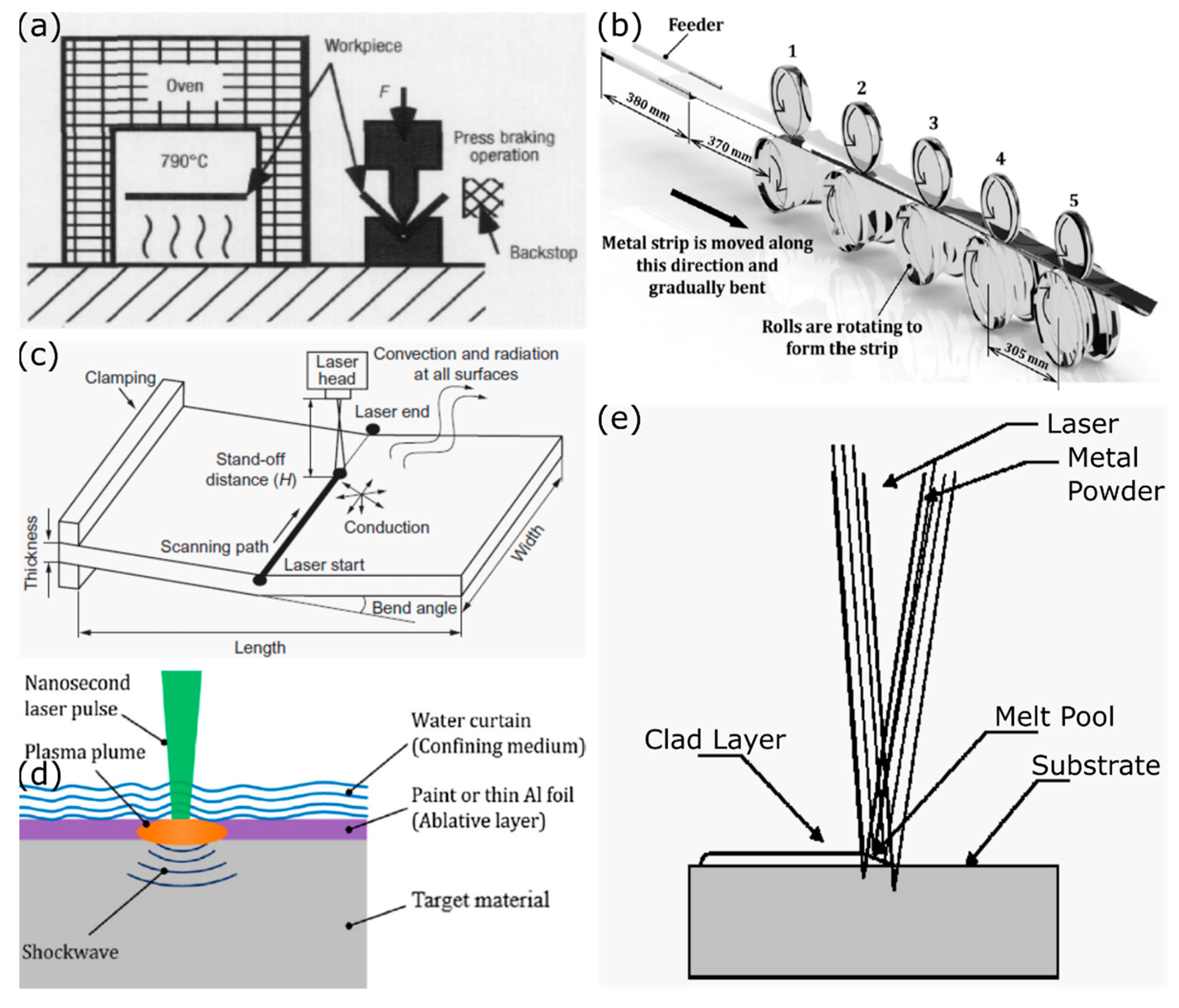
Successful metal origami requires precise control over the bending of the sheets of metal. There are multiple ways to bend metal, the most common methods use expensive equipment, such as press brakes (Figure 2a), or roll formers (Figure 2b) [25,26,27]. Press brakes involves placing the sheet metal over a shaped die and then applying intense mechanical pressure to force the metal into the die. Roll forming involves the gradual bending of the sheet metal by passing through successively narrower rollers. Both processes rely on mechanically deforming the sheet, which leads to a spring-back effect that causes the final bend angle to differ from the dies and rollers, as a result of residual elastic strains after the mechanical pressure is removed [28,29,30,31]. Proper control for spring-break often involves extensive testing of how the brakes and substrates interact [29]. A change of design shape or material means this testing would need to be repeated, making this a poor choice for rapid prototyping.
Another method of metal bending involves thermal stress-induced bending called line heating [34]. Line heating uses a gas torch to carefully heat a piece of metal followed by cooling the part rapidly in water to generate plastic strains that bend the metal. This process, unlike press break forming, is highly labor intensive. Line heating also depends on the craftsmanship of the bender, since the gas torch is a diffuse heat source, which can lead to large heat-affected zones and degraded material properties [35]. Aiming to automate this process, researchers suggested replacing the skill of a bender and flame torches with the highly controllable heat of a laser [35]. The process is similar to line forming, but uses lasers to localize the heating. Thus, these early researchers called this process ‘laser forming’ [36,37].
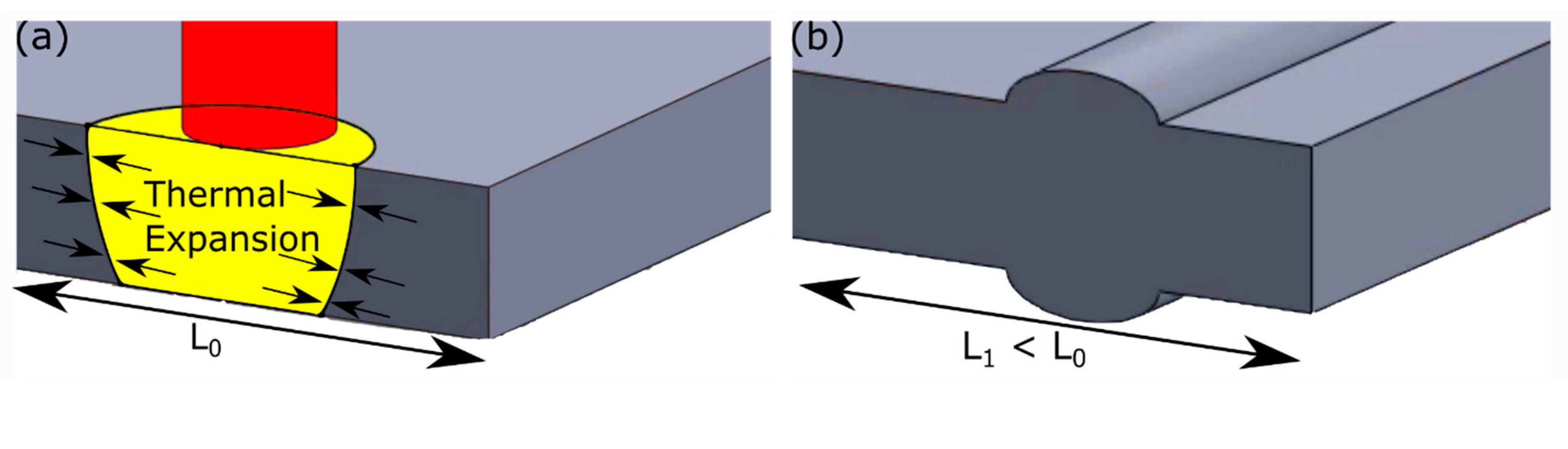
Laser forming is defined as the use of a laser beam to locally heat and introduce thermal stresses to plastically deform a work piece [38]. The interaction of a laser beam and a substrate generates localized thermal gradients (Figure 2c) [36,37] that cause unequal material expansions. The thermal expansions generate stresses large enough to cause the heated material to yield, generating plastic response stresses [39,40]. As the piece cools, the scanned area returns to its normal size and stops straining the surrounding material, but the compressive stresses remain leading to a permanent deformation in the substrate without a spring-back effect [37]. Laser forming consists of several related mechanisms, and is most commonly used for bending but can also be used for shortening/adjusting a work piece [41,42].
While this review uses the term “laser forming” for thermal metal forming processes, as accepted in the related research community, we want to address potential confusion in terminology. Another technique also used for laser bending is laser peen forming (also known as laser shock forming). In laser peen forming (Figure 2d), a short-pulsed laser is focused on a sacrificial coating on top of the workpiece [43]. When the coating ablates, it generates a plasma plume that attempts to expand in all directions [43]. The laser peen forming setup confines this expanding plume, usually with a layer of water, and redirects this energy as a shockwave into the workpiece, leading to bending [43]. This process is entirely mechanical and, thus, susceptible to the similar drawbacks of more conventional fabrication. A recent review of the field can be found elsewhere [44], and this approach will not be covered further here. The term ‘laser forming’ has also been used by researchers in reference to other technologies based on producing (i.e., forming) a material with a laser, including powder bed fusion [45], or laser metal cladding (Figure 2e) [46]. Both techniques use a laser to selectively heat metal powders, causing them to coalesce, but ‘laser forming’ is not the preferred terminology in those fields.
Laser forming was first developed in the 1980s [35], and much of the early research was focused on understanding the complex interaction between the laser and the material properties with a goal of developing formulas that can accurately predict the final bend angle [37,48,49]. A number of studies now exist on modelling of laser forming, including a notable review [38], so we refrain from focusing on these research efforts here. Instead, we aim to survey laser forming as a rapid prototyping strategy for developing 3D structures from flat substrates. The most recent review focusing on the manufacturing applications of laser forming is almost two decades old [50], and there have been many advances in the field since then.
This review of laser forming begins with a discussion of the three dominant sub-mechanisms of laser forming, before discussing how to select appropriate process parameters to achieve a desired bend shape. We then survey the application space of laser forming, from larger scale fabrication to smaller scale rapid prototyping and adjustment, before providing an outlook on current challenges and unresolved problems in the field.
2. Laser Forming Mechanisms
Laser forming is a relatively broad term that refers to the plastic deformation of a workpiece resulting from laser-induced thermal stresses. From experimental studies and finite element modelling of laser forming, three main sub-mechanisms have been identified for understanding laser forming: the temperature gradient mechanism (TGM), the buckling mechanism (BM), and the upsetting (shortening) mechanism, (UM) [36,37,38]. All three mechanisms arise from plastic strains generated in the work piece as a result of the absorbed laser energy, but the dominance of one mechanism over the others depends on how that energy propagates in the work piece [51]. This energy propagation depends on the workpiece geometry and the lasing parameters.
2.1. Temperature Gradient Mechanism (TGM)
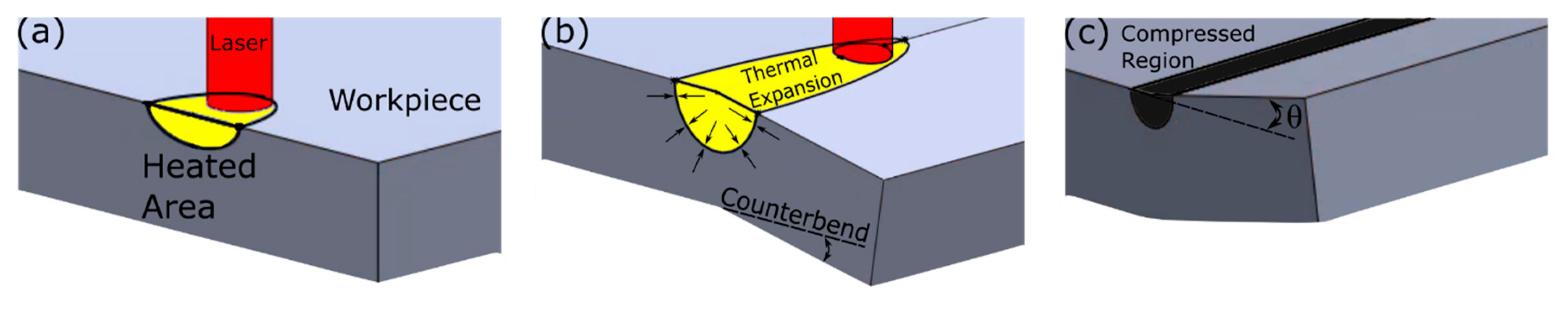
The temperature gradient mechanism is dominant when a thermal gradient is generated through the thickness of the work piece through laser heating [37]. This vertical gradient is achieved with a higher laser scan speed and a thicker substrate (or a thinner substrate with relatively poor thermal conductivity) [52]. The thickness of the material in the TGM case is typically on the order of the laser beam diameter [53,54]. For example, a researcher laser formed sheets between 0.5 and 4 mm thick, using a laser with a beam diameter of 5.2 mm travelling at 1.5 m/min [52]. Once the laser energy is absorbed by the surface of the metal, the temperature rises rapidly (Figure 3a). In most materials, the hotter areas expand, generating stresses on the cooler sections [55]. As the top of the workpiece is much hotter than the bottom, the top of the workpiece expands more than the bottom, leading to a small counter-bend (Figure 3b) away from the laser [38,52]. At these high temperatures, the mechanical properties, such as the Young’s modulus, drop precipitously [56]. At these elevated temperatures, the thermal expansion stresses exceed the flow stress, which means the thermal stresses are large enough to maintain plastic deformation [36,39,40]. The work piece surrounding the thermally expanded portion is stiff and resists the expansion by exerting an equal compressive force [52,55]. Initially, the material bends away from the laser (the counter-bend), and is a consequence of the thermal expansion combined with the decreased yield stress of metals at higher temperatures [36]. Once the piece has time to cool, the material scanned by the laser returns to its normal volume, but the compressive stresses remain in the piece. Consequently, the laser scanned volume is under compression causing the work piece to develop a final bend angle, θ, toward the laser [36,50]. At the cooler temperatures, the mechanical properties return to their higher values which prevents the formation of new plastic stresses, so this bend angle is permanent [38,52,55]. The TGM mechanism, therefore, always results in a bend toward the laser source.
2.2. Buckling Mechanism (BM)
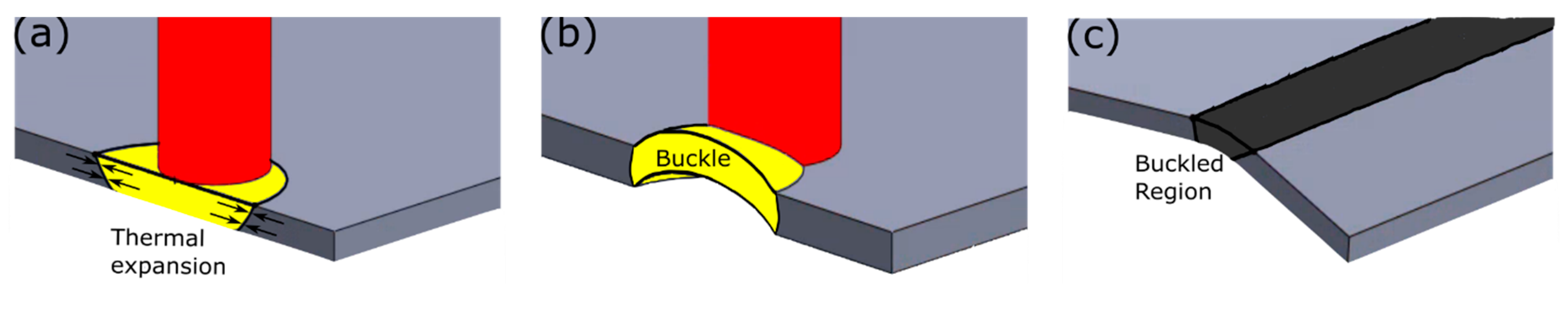
The buckling mechanism also relies on a thermal gradient, but in this mechanism, the work piece is either thinner or has a high thermal conductivity relative to the laser scan speed [36]. The first report of laser forming using the buckling mechanism used a laser beam with a diameter of 0.12 mm traveling at 5 mm/s to laser form 0.1 mm thick steel foils [57]. In this case, there is essentially no temperature gradient through the thickness of the substrate, but rather, the thermal gradient spreads outward from the scan line (Figure 4a) [57]. This means the resulting compressive forces are pushing against each other, generating a buckling instability (Figure 4b) [57]. Consequently, the work piece can bend either toward or away from the laser (Figure 4c) [57]. As an instability, the bending direction should be random, but this assumes the sheet has no residual stresses prior to laser forming [57]. Commercially available materials have a complex internal stress state, because of the hot and cold working that the sheet experiences during manufacturing, and this stress state determines the buckling direction [58]. Complete knowledge of this stress state would allow the bending direction to be predicted [57,58], though this is usually unknown. Beyond predicting the bending direction, researchers have also developed ways to control the buckling direction. Such methods include pre-bending the metal sheet [52,59], or through judicious choice of the lasing parameters [60,61]. The ability to generate bidirectional bending expands the design space for laser forming [62,63], without the need for human input, i.e., flipping the work piece [50]. As bending with the buckling mechanism can occur both toward and away from the laser, there can be some ambiguity which mechanism is occurring. Downward bending currently remains the best confirmation that buckling is occurring, because the TGM only bends the workpiece toward the laser. It has been reported that buckling can lead to larger bend angles per pass [57,58], which suggests the bend angle can be another way to differentiate the mechanisms, though visual downward bending is the easier method.
2.3. Upsetting Mechanism (UM)
The third mechanism of laser forming is the upsetting mechanism [37,64]. The upsetting mechanism begins in a similar manner to the buckling mechanism. The laser scan speed is kept low to prevent a thermal gradient from developing through the thickness of the substrate, generating similar stresses to the buckling mechanism [54]. In the upsetting mechanism, however, the substrate is much stiffer along the scan path, preventing an out-of-plane bend [36,64] (Figure 5). This stiffness can be the result of using a thicker workpiece or one where the material has a higher Young’s modulus [50]. Since the flow stress has been reached, but the substrate is unable to bend, the laser scan path becomes locally thicker and the substrate becomes, consequently, shorter [42]. One of the more comprehensive studies on the upsetting mechanisms reliably shortened 2 mm thick steel plates using 12 mm laser beams scanning at speeds around 1 mm/s [51]. The upsetting mechanism allows for in-plane substrate adjustments, which expands what shapes are laser formable by producing a change in the Gaussian curvature [53,65].
2.4. Coupling Mechanism
Some recent reports have suggested that the three mechanisms described above are not sufficient to capture the full range of experimental results, so they have proposed a coupling mechanism that combines both TGM and the upsetting mechanism [51,64,66]. This combination of forming mechanisms was already discussed [36,57] in early reports, but was not considered a separate mechanism. The proposed coupling mechanism is a consequence of the mechanisms above being idealized, limiting cases. As the laser forming parameters are adjusted, it is reasonable that the other mechanisms might start to play an increasingly important role, especially near the transition region between TGM and buckling [36]. For this reason, the proposed coupling mechanism will not be treated as a distinct mechanism of laser forming here, but it is still important to consider when designing a laser forming process, and is even useful for laser forming certain structures [66].
3. Design Considerations for Laser Forming
3.1. Laser and Substrate Selection
Since its first reports, laser forming has been used to bend sheets of common metals, such as stainless steel [67,68,69] and aluminum [70,71,72], out of plane without mechanical inputs [36,37,67]. As the understanding of the process developed, more varied substrates were explored such as titanium, [27,73] and copper alloys [74,75], hoping to develop new ways to form 3D structures for aerospace and electrical applications. Researchers have also explored laser forming on non-metallic substrates and have bent typically brittle materials such as silicon [76,77,78], ceramics [41,79], and glass [79,80]. More recently, there have also been demonstrations of the laser forming of more complex structures, such as metal foams [81,82] and laminates [83]. Despite the success of laser forming non-metals, metal bending has remained the primary application of laser forming, due to the use of metals as engineering materials in applications such as ship hulls [35,54,84]. There have also been some reports of laser forming of a limited number of polymers [85,86], although polymer laser forming remains relatively rare. Laser forming, therefore, is a general process reliant on controlled heating to generate plastic stresses, and appears possible for most materials. Large bending angles are more readily realized in metals as their ductility helps avoid crack formation at the bend line, [80,82] though experimental results suggest that the maximum bend angle is a strong function of material thickness with thinner samples being able to demonstrate larger bend angles [79,82,87]. Studies of many of the more well-studied substrates have been able to demonstrate deformation by all three mechanisms. Laser forming of the more exotic materials tends to be realized using the TGM, [76,80,82] though BM has been demonstrated in glass [79] and UM in silicon.
Critical to the success of the laser forming process is appropriate coupling of the laser energy to the material being formed. This coupling can be achieved by selecting the appropriate laser wavelength that corresponds to the absorption maximum of the substrate [75,88], by using a much higher power laser, so sufficient energy is absorbed by the substrate even with low absorptivity, or by using an absorbing coating layer that is matched with the laser wavelength being used (Figure 6) [85,89]. Metals thicker than 100 nm are optically opaque [90] and do not transmit appreciable amounts of light, so the metal substrates that have been used in laser forming will primarily either reflect or absorb the laser energy. The percentage of the incoming laser energy that is reflected is called the reflectance and these values have been measured as a function of wavelength [91]. The most common lasers [27] used for laser forming are Nd:YAG lasers that operate at 1.064 μm [57,58,76,78,85,86,92,93] and CO2 lasers that emit at 10.6 μm [39,50,54,68,89,94,95,96]. CO2 lasers are common in industrial setting, as they were one of the first gas lasers developed [97] and exhibit a high energy efficiency, while operating as a continuous-wave mode at high average powers (>1 kW); however, their absorption into metals is low and an absorbing coating is often required. Nd:YAG lasers are popular in industry as the 1.064 μm output wavelength is better absorbed by metals for cutting and welding, so absorbing coatings are not needed.
The early reports focused on using high power (>1 kW) lasers [40,60,61,70,71,98,99,100,101,102,103], as the intent was to bend large sheets as part of the ship building process [35]. The laser forming of thinner substrates enables the use of lower power (<100 W) lasers, such as those found in commercial metal marking laser systems [57,63,67,76,85,88,93,104].
Studies on the laser forming of plastics took advantage of the high transmissivity of high-density polyethylene (HDPE) to the wavelength of the Nd:YAG laser [85,86]. The laser energy was absorbed by a resinous black coating applied to the surface of the plastic. The laser power was kept low and the scan speed high, to ensure that the bending occurred through the temperature gradient mechanism, which reliably generates bending toward the laser. As expected, this was observed when the resin was on the side of the plastic exposed to the laser. With the same process parameters, but the coating placed on the opposite side, the plastic was reliably bent away from the laser. This downward bending should not be possible if using the TGM, but the optical transparency of HDPE to the laser made the system behave as if it was exposed to a laser on the underside and the TGM was causing the plastic to bend that direction. This same technique could be adopted for laser systems with multiple wavelengths, as glass absorbs the radiation from a CO2 laser, but is transparent to the light from a Nd:YAG laser. Thus, sealed metal structures could still be bent if there is a glass window for the laser to pass through [105]. As seen in Figure 6, some metals, such as copper, are highly reflective to the fundamental wavelength of the Nd:YAG laser (1.064 μm). Consequently, laser forming copper with a Nd:YAG laser requires a substantially higher power or the use of a different wavelength. Recently, laser forming was demonstrated with other laser systems that might be commonly found in research environments, such as fiber lasers [106], exciplex lasers [74], and even Ar-ion lasers [67], which expand the substrate choice for laser forming.
Once the appropriate laser/substrate matching has been done, judicious selection of process parameters is essential to the laser forming process, as the laser power and scan speed control which mechanism is dominant [37]. Typically, laser power is kept low and speeds high to ensure that the substrate is being bent by the TGM, generating reliable bending toward the laser. As the TGM only generates a bend of one or two degrees per pass or less [38,74,101], many passes are needed to create structures with large bend angles, sometimes taking as many as 150 passes to produce a full 90 degree bend [88].
3.2. Cooling Effects in Laser Forming
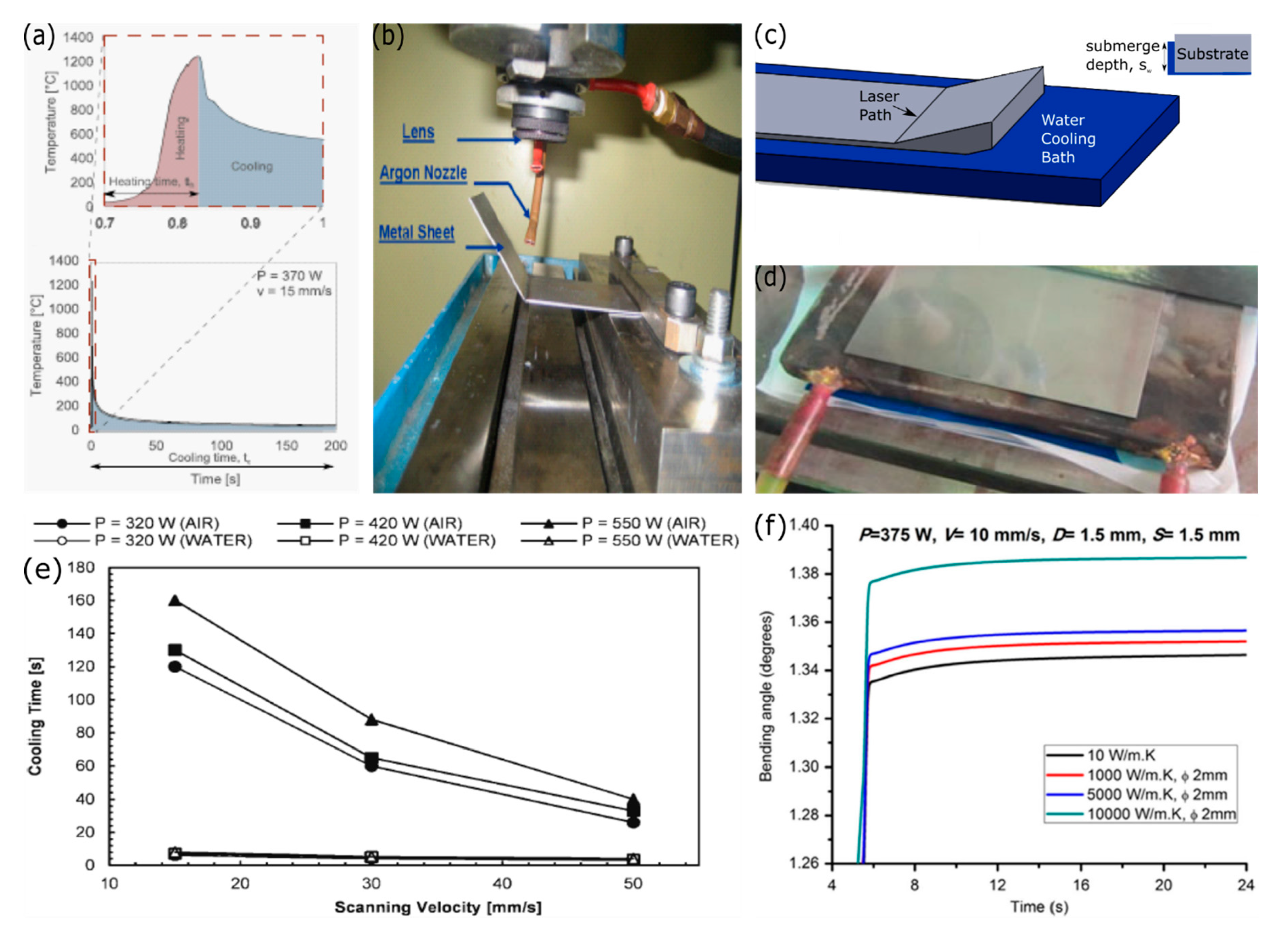
To ensure that the same thermal gradient is established with each laser pass, an appropriate cooling time must also be built into the laser forming process. Consistent laser forming requires that the workpiece be cooled to the same thermal state in between each laser pass. The majority of laser forming setups use free convection with the surrounding air to cool the workpiece, which is relatively slow and leads to a pronounced increase in processing time (Figure 7a). In fact, cooling can be the longest part of a laser forming process [52,59,86,107]. To reduce the processing time, researchers have proposed multiple methods for forced cooling such as forced convection with compressed gas streams aimed at either side (Figure 7b) [92,108], passive water cooling with the bottom of the workpiece being placed in a water bath (Figure 7c) [109,110,111], and forced liquid cooling, such as a circulated cooling fluid placed in contact with the bottom of the substrate (Figure 7d) [112,113,114,115]. All these methods showed a pronounced reduction in the total processing time, as the workpieces cooled to room temperature in a matter of seconds, with active water cooling showing the largest reduction in processing time.
Active cooling systems are not typically desirable when designing manufacturing processes, as they require pumps that increase both capital and operating costs of the process, but they are acceptable if the active cooling offers a substantial decrease in processing time or improvement in the reliability of a process. Fortunately, passive water cooling has also been demonstrated to provide sufficient reductions in processing time (Figure 7d) that active cooling may not be needed [109]. Some researchers have reported that forced cooling can lead to an increased bend angle per pass (Figure 7e) under the same lasing conditions, but reports differ on how pronounced this effect is, with some arguing there is no measurable effect [35,108,109,112,113]. Overall, integrated cooling systems offer a way to increase the throughput of laser forming by greatly reducing the time needed to establish thermal equilibrium in between laser passes for multi-pass forming.
The processing time can be further decreased by using the buckling mechanism as buckling is capable of generating larger bending angles per pass than the TGM, because more energy is put into the workpiece [56,57]. Typically, laser forming using the buckling mechanism is avoided as the mechanism is fundamentally an instability and so the workpiece can bend either toward the laser or away from it [57]. This instability is theoretically random but can be controlled by multiple factors, such as external loads [57,104], or the relaxation of internal stresses that exist because of the cold-working of common metal sheets [57]. The main reason to use the buckling mechanism is the downward bending, which greatly broadens the number of structures that can be laser formed [59,61].
3.3. Macro-Scale Laser Forming
Early research efforts were focused on macro-scale laser forming of sheet metals that are millimeters thick [35,50,103]. Among the macro-scale design targets were ship hulls [35,84], fuselage panels [70], and car doors (Figure 1g) [33]. These structures highlight different uses for laser forming in a manufacturing environment, as ship hulls and fuselage panels are low-volume parts, whereas car doors are high-volume components. Laser forming is considered less desirable for manufacturing high-volume metal parts, as it cannot compete with the speed of conventional methods, because the laser forming process is dominated by the cooling time needed between laser passes [33,50,52,114].
Both high-volume and low-volume products need to be joined to other parts, which is the second use for laser forming in manufacturing of macro-scale objects. Metal parts are often joined via welding, which can introduce distortions and lead to misalignment [35,116]. These distortions arise from two main contributions. First, the high heat of welding introduces thermal stresses similar to laser forming [116]. Second, the heat of welding releases stored plastic strains that result from mechanical forming [35]. While the distortions from welding are often small, they still need to be corrected, and laser forming offers a way to address these problems in a process known as hybrid laser forming [50,54,117,118]. Accurate manipulation of metals near weld lines is, however, challenging, because the local weld distortion is not uniform due to the complex stress state generated during welding [119].
The ability to shape large 3D objects using only a laser offers promising opportunities, such as remote deployment, the production of replacement parts where they are needed rather than at a centralized facility and shipped. In the 1980s, it was proposed that laser forming would be a valuable technology in space [103]. A laser system is more compact than a hydraulic press and the high energy efficiency of CO2 and diode lasers lowers the energy consumption required for metal bending. Laser systems also offer the potential for cutting the workpiece [59] and joining [120] it with other pieces that traditional press brakes do not, making laser systems valuable for areas with minimal electricity generation or limited space.
3.4. Laser Forming Curved Surfaces
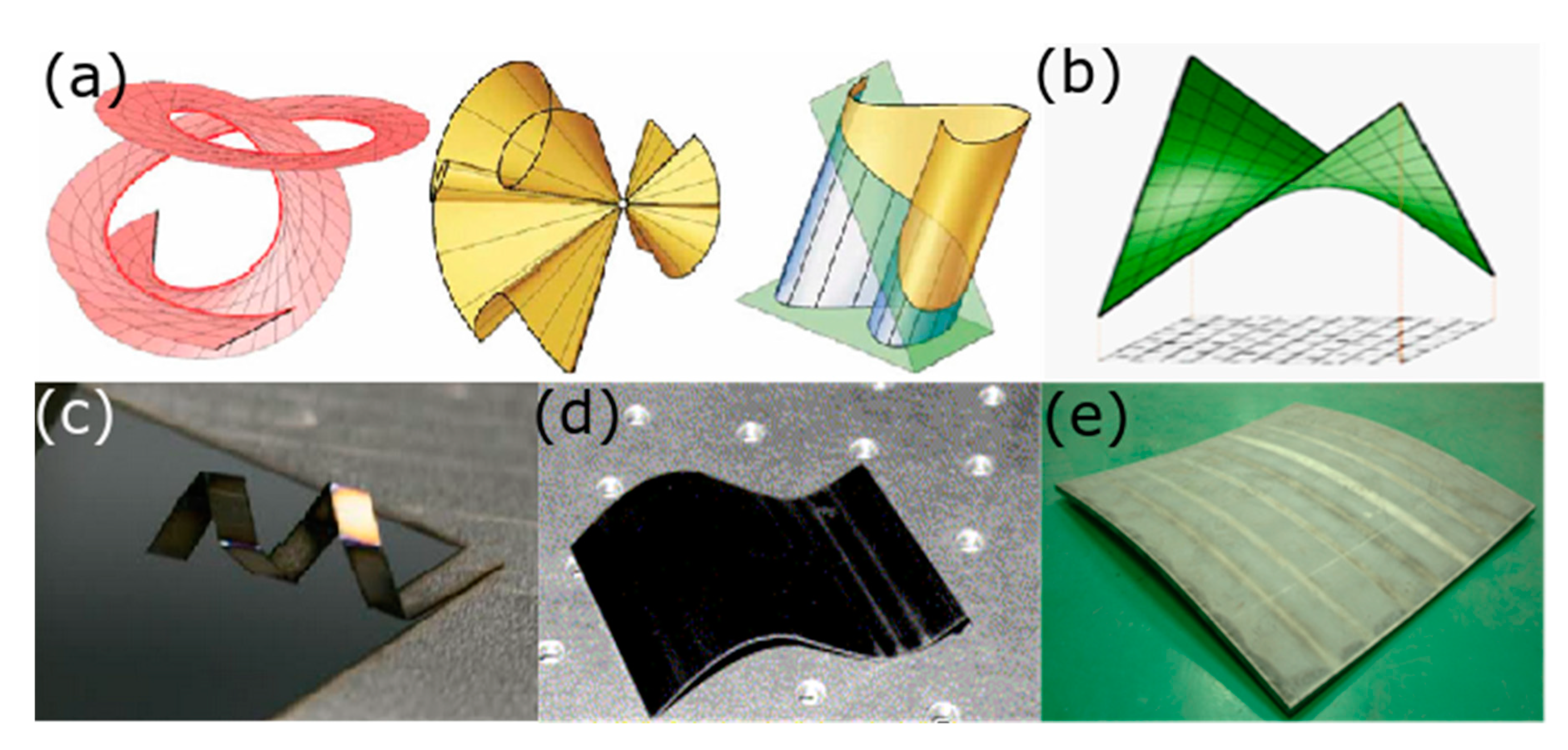
Ship hulls are an example of a doubly curved structure and so researchers needed to design methods of introducing curvature into laser formed parts [53]. Currently, there are two main methods for developing curvature in laser formed parts. The first is to make multiple bend lines close to each other [33,68,121], approximating a smooth curve as the limit of many bend lines close together (Figure 8d). By adjusting the distance between the laser passes, bends of varying curvature are able to be produced, as the heat affected zone is not limited to the laser pass line [68]. As this curvature is produced by simple bends, the resulting structures are considered developable surfaces [65]. Developable surfaces are the family of surfaces that can be produced by transforming a plane as long as the Gaussian curvature remains unchanged (Figure 8a) [65]. This means bending, rolling, and cutting are permitted, but stretching or compressing a region are forbidden [65]. As developable surfaces are produced from bending and folding, much of the knowledge gained in origami engineering is applicable to producing structures with laser forming [1,14,26,122,123].
The second method to produce curved structures relies on the upsetting mechanism that produces in-plane strains [53]. These planar strains cause local distance to be distorted, changing the Gaussian curvature of the workpiece [53,124], which simple bending does not. Since the strain changes the Gaussian curvature, the final workpiece is considered a non-developable surface,, as developable surfaces have zero Gaussian curvature [65]. Non-developable surfaces include hyperbolic paraboloids (Figure 8b) and hyperboloids, which are often called saddles (Figure 8e) [53,84] and pillows [53], respectively, in the laser forming literature. The ability to generate these surfaces from flat sheets using laser forming greatly expands the design space of 3D structures that can be rapidly prototyped.
While the majority of laser forming research has been done on planar substrates, some researchers have investigated laser forming as a means to bend metal tubes for heat exchangers and engines [40,125,126,127]. Laser formed tubes bend toward the laser, though researchers disagree about what mechanism is causing the bending. Some suggest the TGM is causing the bending [126], while others suggest that the stiff nature of metal pipes means that the upsetting mechanism is dominant, leading to a local shortening, which causes the tube to bend toward the laser without a spring-back effect [40,128]. Like the laser forming of sheets, laser tube bending is a highly flexible method that does not require specially designed dies. This makes laser tube bending valuable for rapid prototyping, as well as low volume, customized production [126]. When bending tubes, it is important to consider the distortion of the tube cross-section, or ovalization [40]. Multiple reports have confirmed that laser tube bending tends to produce less ovalization than mechanical bending, as the laser induced stresses are less than the mechanical forces used when cold bending the tubes [40,126].
Matching the optical absorbance of the substrate with the laser output allows the energy to couple more effectively, lowering the laser power required for successful laser forming. As lower powered (<100 W) laser cutting systems proliferated, researchers hoped to use these systems for laser forming as well as laser cutting. Laser cutting requires high laser fluences, so the beam size needs to be small to achieve clean cuts. Since the output power is lower, the fluence is kept high by decreasing the spot size. For successful laser forming, the laser spot size is typically the same order of magnitude as the substrate being bent which has led researchers to experiment with the laser forming of smaller and thinner substrates [67,72,129].
3.5. Micro-Laser Forming
Complex, 3D silicon microstructures are difficult to produce because silicon is a brittle material that requires high temperatures and specialized tools to produce the desired shape [130]. Laser forming has been applied to adjusting silicon microstructures [76]. The precise control of heating enables silicon microstructures to be bent out of plane, even with more thermally sensitive components, as long as the thermally sensitive components are not located near the laser scan path. Laser forming is not heavily used for the rapid prototyping of MEMS structures, but has been found tremendously successful as a quality control technique called laser micro-adjustment [64,131]. Laser micro-adjustment is a valuable application of laser forming, as evidenced by the industrial adoption of the technique [41,131,132].
Laser micro-adjustment uses a laser to make submicron final adjustments to microstructures [106,133]. Any of the mechanisms can be used for this adjustment, but the smaller bending angle per pass makes the TGM preferable to the buckling mechanism for out-of-plane bends [38,64]. The upsetting mechanism is useful for shortening the workpiece locally which has been used for aligning actuators [42,133]. The laser forming mechanism can be easily determined by adjusting the lasing parameters [36], but the size of the sheets being micro-adjusted makes edge effects more common [134], and increases the coupling between the TGM and the upsetting mechanism [64,101,106,135]. This coupling leads to both in-plane shortening and out-of-plane bending, which is especially common in actuators. Bridge actuators are micromechanical structures that hold functional components and allow fine adjustments to the final positioning to be made. Bridge actuators are produced by removing most of the structural material in a small area, so that they are connected by thin strips called bridges. When laser forming a two-bridge actuator, the scan path effectively creates two hot and two cold sides, the usual irradiated and unirradiated sides of the work piece, as well as a hot bridge and a cold bridge. The usual irradiated sides produce the out of plane bending, while the hot bridge causes an in-plane bend [42,135]. While actuators are one of the most common pieces laser micro-adjusted, the process is general and has been applied to multiple devices [136] and companies have filed for patents on using laser adjustments based on these reports [137,138,139]. There has also been a promising report of the laser forming of shape memory alloys, a material commonly used for MEMS actuators, although this forming has not yet been done on MEMS structures [140].
One application of laser micro-adjustment is the precise alignment of optical fibers to ensure optimal coupling with a photonic integrated circuit (PIC) [141]. While glass has been successfully laser formed [81,82], laser forming the optical fiber would only produce bends into the fiber, rather than aligning it. To align the optical fiber, the researchers sheathed the fiber into a thin metal tube and the tube was then laser formed [141,142]. The optical fiber is flexible, so the bend in the metal tube will cause a deflection in the fiber tip. In effect, the metal tube is being used as an alignment actuator with sub-micron precision, owing to the controllability of laser forming [141,142].
3.6. Laser Forming for Rapid Prototyping
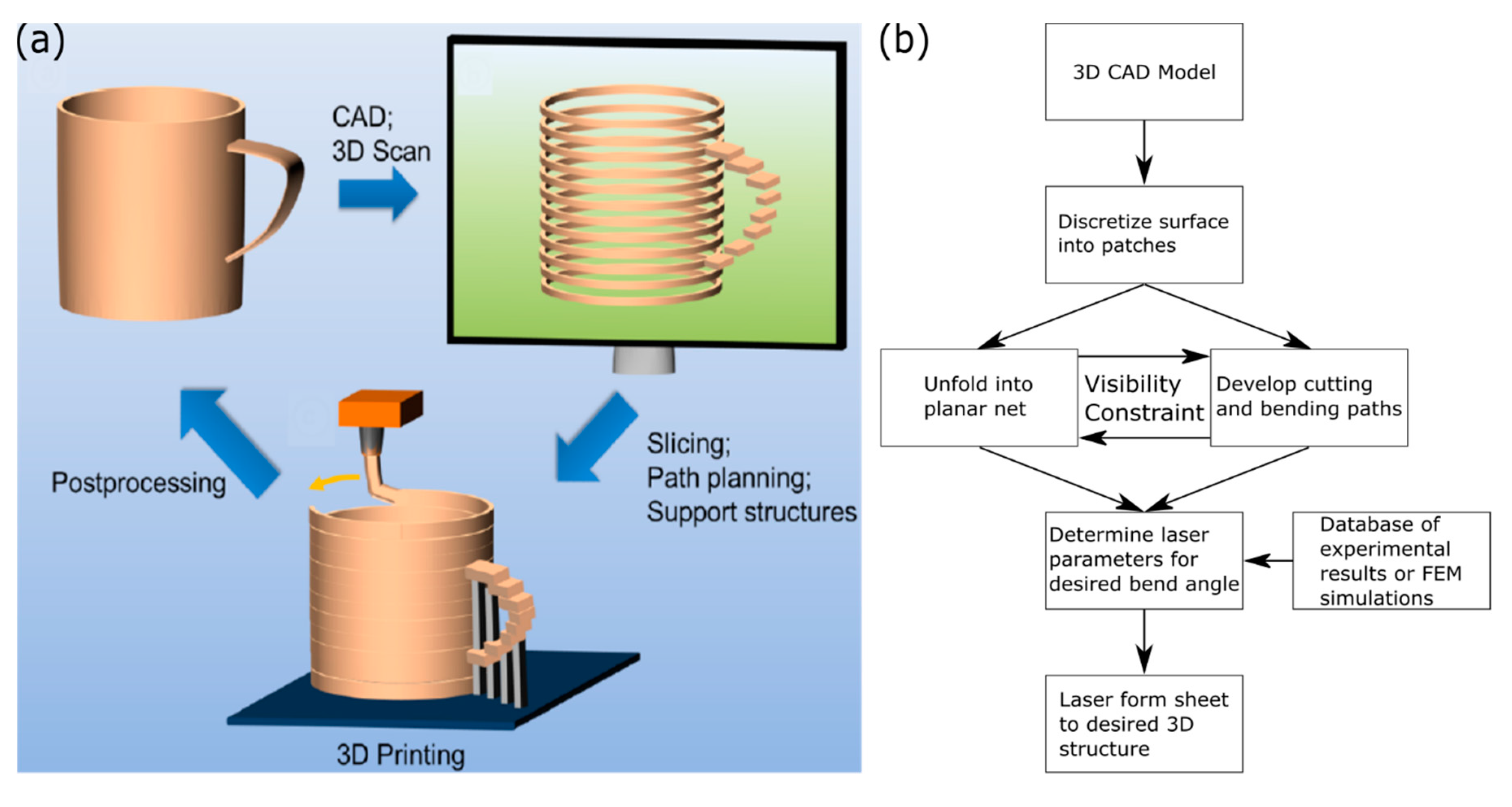
The flexibility of laser forming makes it a promising technology for rapid prototyping, and researchers have identified rapid prototyping as one of the areas where laser forming is most likely to make meaningful contributions in the industrial product lifecycle [50]. This promise remains largely unfulfilled compared to more conventional 3D printing for various reasons. Despite the many different methods for 3D printing, such as fused filament fabrication [143,144] and stereolithography [145,146], 3D printing follows the same general workflow to produce a printed object from a computer aided design (CAD) file (Figure 9a). Once the engineer has designed the object they want to be 3D printed using a CAD software, they need to export it to a format that can be 3D printed [19]. The default file format for the additive manufacturing community is the STL file format, which approximates the surface of the CAD object as a collection of tessellated triangles [147]. Since 3D printers build structures in a layer-by-layer fashion, the STL file needs to be passed to a slicer, which converts the 3D object to the build layers. From this file, the scan path is developed, and support structures are calculated if the object needs them. For modern 3D printing, the conversion of the CAD file to printed object is entirely automated [19,147]. Critical to the broad adoption of laser forming for rapid prototyping is developing a similar software structure that can convert a CAD file into a path planning program, which also calculates the appropriate lasing setting to produce the desired 3D object without human intervention. Extensive research efforts have been undertaken to achieve this goal, with recent results suggesting that this goal might be realized soon [62].
One of the first complex objects successfully prototyped using laser forming was a car door (Figure 1g) [33]. This demonstration is notable for many reasons, chiefly the entire production was done in the laser system. The researchers started from a blank sheet of metal that was laser formed to produce the desired bends, and the final structure was cut from the sheet using the same laser. As the buckling mechanism was only recently reported and control strategies were limited, the researchers were laser forming only using TGM. The complex shape of the car door required both concave and convex bending, so the workpiece needed to be manually flipped to produce the bi-directional bending needed for the car panel. While these experiments involved no prediction of laser settings, the researchers introduced a novel feedback system, where the scanning speed was adjusted to produce the desired bend angle. Additionally, a car panel might be considered far from an arbitrary design, so the scan pattern was relatively easy to design.
To produce more complex objects via laser forming, it is necessary to know which bend lines are needed to produce a given shape, a classic origami problem [1]. To this end, the inverse design of scan strategies to generate a desired laser formed structure has been a productive research topic [53,66,84,99,148,149,150,151]. The design of irradiation paths involves more than planning where the beam needs to be applied to generate a desired shape, but also the laser power and travel speed, to produce the desired degree of bending using the appropriate forming mechanism. These requirements remain a challenge, and have required researchers to design algorithms that plan a scan path and guesses appropriate lasing settings by consulting a database from experiments [99] or finite element simulations (Figure 9b) [53,121,150]. Despite the known disagreement between experimental results and simulations [38], these scan strategies are able to produce the final desired structures with a high degree of accuracy [53,121]. One limitation of these design systems is the limited degree of bending required in the validation structures. As the bend angles required per point are small to moderate, the relationships between bend angle and line energy (laser power divided by scan speed) is approximately linear [98,99]. As the laser spot size gets smaller and the required bending angle approaches 90 degrees, this linear relation fails to hold [88,152] and none of these design strategies account for this deviation. These limitations are more prominent, as engineers have started using laser forming to produce highly complex structures.
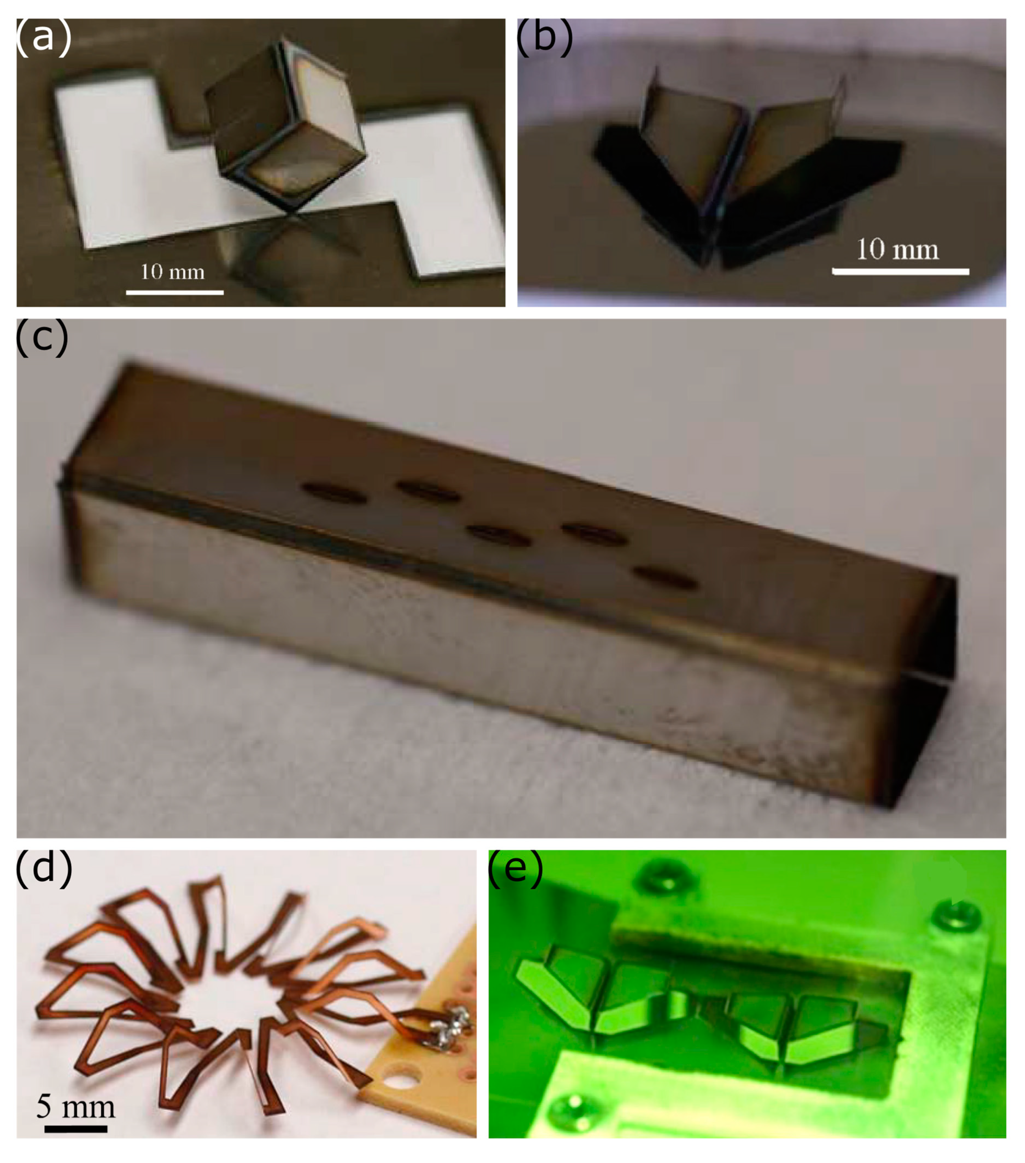
Realizing that laser forming was not limited to moderate bending, but could be used for larger folds (up to ninety degrees or higher), our group began envisioning what origami structures can be produced with laser forming. Laser forming with TGM is limited to ninety-degree bends, as further bending results in the workpiece blocking the laser path, but this limitation does not exist if using the buckling mechanism to bend away from the laser. Using both mechanisms, we were able to produce complex objects, such as cubes (Figure 10a) and airplanes, (Figure 10b), without the need for human intervention [59]. Similar to the car door forming [33], the outline of the shape was manufactured from metal sheets by using the laser to also cut the final structure, releasing it from the sheet. By using a Nd:YAG laser instead of a CO2 laser, an absorbing coating was not needed, allowing for marking of the metal at low powers. Rapidly producing these structures from a blank metal sheet using multiple bending modes and laser cutting demonstrated the potential for laser forming to be a viable rapid prototyping strategy.
Soon after, we showed that laser forming could be used to produce electronic devices, such as antennas [153] and inductors [88]. When producing the antennas, a blank metal sheet was clamped on all sides, before laser cutting the slots for the array antenna and the perimeter of the waveguide was laser cut from the metal sheet, before the entire structure was bent to produce the final structure: a rectangular prism (Figure 10c) [153]. It was worth noting that the laser cutting made more precise cuts than electro-discharge machining, the usual technology used to produce the slots in the waveguide. In fact, the entire laser process of cutting and bending was faster than conventional machining that only produces the slots. Efficient waveguides require smooth surfaces to minimize losses [154], so new manufacturing techniques need to show that they do not greatly alter the metal surface. The impact of laser forming is limited to the laser scan paths and even after 100 passes only showed a modest increase of the surface roughness of 0.5 μm [155]. Similarly, the coils for the inductor were cut from a blank piece of copper before being bent out of plane to generate a toroidal inductor (Figure 10d) [88]. Laser forming can also be used to produce an inductor with an overpass or bending the inductor out of plane. Bending inductors out of plane offers a way to improve the Q-factor as eddy currents and skin effects are minimized [156], which is especially important for integrating these elements on semiconductor integrated circuits. Both reports demonstrated that laser forming could be used to rapidly prototype functional devices, as the designs can easily be iterated, as it only requires changing the location or size of lines in a 2D CAD drawing. This process, however, still requires human input to exchange the metal sheets between design iterations, which would limit the industrial adoption of laser forming for rapid prototyping or producing custom parts.
Working to automate the entire laser forming process, our group developed a roll-to-roll laser forming system, with the metal feedstock passing through the focal plane of the laser [63]. This set up allowed features to be readily cut and folded from the sheet metal using the TGM. Additionally, the metal sheet had a pre-strain from being wound onto a roll that was used to reliably generate downward bending using the buckling mechanism, producing the same complex shapes from our previous work in an automated process (Figure 10e). Once the piece was formed, it was released from the sheet and fell down a chute, before the rolls were spun to introduce a new working area. This was the first demonstration of a fully automated laser forming process to produce complex 3D structures. While impressive, producing these structures relied on our previously designed scan paths and laser settings. For many of the structures, we relied on the self-limiting nature of ninety-degree bends, so that precise control over the laser settings was not needed. Accurately determining the laser power, speed, and number of passes would be required, if the desired structures included intermediate bends.
Figuring out what scan path and what lasing setting are needed to produce a desired structure is known as the inverse design problem, and has been intensively studied [53,66,99,148,149,150]. Part of the difficulty of designing laser scan strategies is the highly-coupled and nonlinear thermo-mechanical nature of laser forming, so many of the previously proposed strategies are limited in the number of scan lines [66,99,150] or are computationally intensive, relying on full finite-element models [148,149]. Recently, researchers introduced an algorithm that takes a desired 3D structure as an input, and simultaneously unfolds the structure into a planar net and plans the cutting and bending paths for this net [62]. For normal origami, the planar net and the bending path can be solved for separately, because the craftsmen is able to access all needed fold lines at any given time [6]. As current laser forming setups rely on an unobstructed optical path between the laser and the fold line, this visibility constraint effectively couples the two problems.
Over the years, laser forming has emerged as a viable rapid prototyping strategy that is complementary to metal 3D printing. Understanding of the sub-mechanisms has allowed researchers to develop scan strategies for many 3D shapes, but the complex thermomechanical process makes it near mandatory to automate this process. This need becomes most pronounced when more complex 3D structures and devices are being laser formed, especially ones that require multiple forming mechanisms. Solutions to this inverse design problem are rapidly developing, and will hopefully make laser forming as accessible as 3D printing.
4. Conclusions and Outlook
Laser forming has developed dramatically over the past forty years, from a mechanistic understanding of the process to the successful laser origami of complex 3D shapes and the algorithms to design their laser scan patterns. As the field matures and laser forming is adopted as a viable rapid prototyping strategy, new research opportunities abound. Like any other prototyping technology, laser forming is valuable for certain structures, while not being preferable for others. Deciding if laser forming is the preferred fabrication methods requires design heuristics that have yet to be clarified. Continued research efforts should be focused on clarifying these heuristics, while expanding the capabilities of the laser forming by developing it as a robust technology that is able to reliably produce functional, near-arbitrary 3D structures from flat substrates in an automated manufacturing environment. To this end, researchers will need to address current gaps in the understanding of the laser forming process, which will inform the design and control algorithms.
Laser forming involves rapid heating and cooling cycles that can cause changes in the microstructure of the metal during the process. Microstructural control is very important for titanium pieces in the aerospace industry, as the mechanical properties and fatigue resistance of titanium and its alloys are highly dependent on having precise control over the grains. Preliminary reports suggest that laser forming leads to unfavorable grain structures in titanium [27,95,157]. Other industries and applications might not have as stringent requirements on the grain structure, but these reports suggest there may be some degradation in the mechanical properties of laser formed parts compared to mechanically bent structures, an area that needs further investigation.
The microstructure of a material influences more than mechanical properties, so these other properties need to be considered when deciding to laser form an object. Of particular concern to the shipbuilding industry might be corrosion resistance to the salty ocean water. The corrosion resistance of some laser formed metals has been briefly investigated [96,115,158,159], with many metals demonstrating a reduced corrosion resistance resulting from the disturbed microstructure. Interestingly, some alloys showed an increased corrosion resistance after being laser formed [159], though the role of the lasing parameters on this phenomenon was underexplored. There is a need to study systematically the suitability of a laser formed material for use in a corrosive environment as a function of the material’s properties, the nature of the corrosive species, and the laser forming parameters. Applications could include ship hulls in salt water, or a laser bent tube in a chemical processing plant.
For laser forming to move from academic research to an industrial process, stronger control schemes and predictive modelling need to be developed. The state-of-the-art algorithms either develop the optimal laser settings for relatively simple shapes based on finite element modelling, or they use experimental data to develop a laser scan path to produce near-arbitrary 3D shapes. The next step would be to develop an algorithm that combines these methods to develop a scan path for near-arbitrary shapes and the optimal laser settings to produce this shape, as some regions might only need bending, while others require shortening. Combining these algorithms would enable additional constraints to be designed around, as the laser-substrate interaction does more than just bend the workpiece.
Most laser forming setups are run in a batch process with one sheet being bent at a time. A recent report demonstrated a way to transform laser forming into a continuous roll-to-roll process by combining laser cutting and bending [63]. Lasers are used to do much more, such as welding [120,160], marking [161,162], laser-induced chemistry [163,164,165], and are even used in analytical techniques [166,167]. Taken together, one could imagine a fully automated process wherein blank sheet metal is fed, then different lasers will cut, mark, chemically pattern, and then fold it into a desired 3D structure with inline quality control. Developing such a system will require developing further control schemes to know when and where to bend the structure in this complex process to yield the desired result.
Laser forming is a valuable technology that is poised to address two notable shortcomings of metal 3D printing—large structures and thin structures. Fully realizing this potential will require developing a detailed understanding of how the laser forming process impacts material properties to produce advanced planning and control schemes. With a completely automated process, laser forming will be available to make the rapid prototyping of metallic structures even lighter.
Author Contributions
A.L.B. performed the literature survey and wrote the initial draft of the paper. M.D.D. supervised the work and edited the paper. N.L. supervised the work and edited the paper. All authors have read and agreed to the published version of the manuscript.
Funding
The research was funded by the Army Research Laboratory and was accomplished under Cooperative Agreement Number W911NF-20-2-0243.
Acknowledgments
The views and conclusions contained in this document are those of the authors and should not be interpreted as representing the official policies, either expressed or implied, of the Army Research Laboratory or the U.S. Government. The U.S. Government is authorized to reproduce and distribute reprints for Government purposes notwithstanding any copyright notation herein.
Conflicts of Interest
The authors declare no conflict of interest.
References
- Turner, N.; Goodwine, B.; Sen, M. A review of origami applications in mechanical engineering. Proc. Inst. Mech. Eng. Part C J. Mech. Eng. Sci. 2016, 230, 2345–2362. [Google Scholar] [CrossRef]
- Hernandez, E.A.P.; Hartl, D.J.; Lagoudas, D.C. Introduction to Active Origami Structures. In Active Origami; Springer: Cham, Switzerland, 2019; pp. 1–53. ISBN 978-3-319-91865-5. [Google Scholar]
- Felton, S.; Tolley, M.; Demain, E.; Rus, D.; Wood, R. A method for building self-folding machines. Science 2014, 345, 644–646. [Google Scholar] [CrossRef]
- Taylor, A.; Miller, M.; Fok, M.; Nilsson, K.; Tsz Ho Tse, Z. Intracardiac Magnetic Resonance Imaging Catheter With Origami Deployable Mech. Med. Devices 2016, 10, 020957. [Google Scholar] [CrossRef] [Green Version]
- Takano, T.; Miura, K.; Natori, M.; Hanayama, E.; Inoue, T.; Noguchi, T.; Miyahara, N.; Nakaguro, H. Deployable antenna with 10-m maximum diameter for space use. IEEE Trans. Antennas Propag. 2004, 52, 2–11. [Google Scholar] [CrossRef]
- Tachi, T. Origamizing Polyhedral Surfaces. IEEE Trans. Vis. Comput. Graph. 2010, 16, 298–311. [Google Scholar] [CrossRef] [PubMed]
- Zirbel, S.A.; Lang, R.J.; Thomson, M.W.; Sigel, D.A.; Walkemeyer, P.E.; Trease, B.P.; Magleby, S.P.; Howell, L.L. Accommodating Thickness in Origami-Based Deployable Arrays. J. Mech. Des. 2013, 135. [Google Scholar] [CrossRef]
- Lang, R.J.; Tolman, K.A.; Crampton, E.B.; Magleby, S.P.; Howell, L.L. A Review of Thickness-Accommodation Techniques in Origami-Inspired Engineering. Appl. Mech. Rev. 2018, 70, 010805. [Google Scholar] [CrossRef] [Green Version]
- Tachi, T.; Hull, T.C. Self-Foldability of Rigid Origami. J. Mech. Robot. 2017, 9. [Google Scholar] [CrossRef]
- Lang, R.J.; Howell, L. Rigidly Foldable Quadrilateral Meshes From Angle Arrays. J. Mech. Robot. 2018, 10, 021004. [Google Scholar] [CrossRef] [Green Version]
- Zirbel, S.A.; Trease, B.P.; Magleby, S.P.; Howell, L.L. Deployment Methods for an Origami-Inspired Rigid-Foldable Array. In Proceedings of the 40th Aerospace Mechanisms Symposium, Baltimore, MD, USA, 14–16 May 2014; NASA Goddard Space Flight Center: Greenbelt, MD, USA, 2014. [Google Scholar]
- Morgan, J.; Magleby, S.P.; Howell, L.L. An Approach to Designing Origami-Adapted Aerospace Mechanisms. J. Mech. Des. 2016, 138. [Google Scholar] [CrossRef]
- Whitney, J.P.; Sreetharan, P.S.; Ma, K.Y.; Wood, R.J. Pop-up book MEMS. J. Micromech. Microeng. 2011, 21, 115021. [Google Scholar] [CrossRef] [Green Version]
- Ahmed, S.; McGough, K.; Ounaies, Z.; Frecker, M. Origami-Inspired Folding and Unfolding of Structures: Fundamental Investigations of Dielectric Elastomer-Based Active Materials. In Smart Materials, Adaptive Structures and Intelligent Systems; American Society of Mechanical Engineers: Houston, TX, USA, 2013; p. V001T01A029/1-6. [Google Scholar]
- Hayes, G.J.; Liu, Y.; Genzer, J.; Lazzi, G.; Dickey, M.D. Self-Folding Origami Microstrip Antennas. IEEE Trans. Antennas Propag. 2014, 62, 5416–5419. [Google Scholar] [CrossRef]
- Tolley, M.T.; Felton, S.M.; Miyashita, S.; Aukes, D.; Rus, D.; Wood, R.J. Self-folding origami: Shape memory composites activated by uniform heating. Smart Mater. Struct. 2014, 23, 094006/1–9. [Google Scholar] [CrossRef]
- Wang, D.H.; Tan, L.-S. Origami-Inspired Fabrication: Self-Folding or Self-Unfolding of Cross-Linked-Polyimide Objects in Extremely Hot Ambience. ACS Macro Lett. 2019, 8, 546–552. [Google Scholar] [CrossRef]
- Upcraft, S.; Fletcher, R. The rapid prototyping technologies. Assem. Autom. 2003, 23, 318–330. [Google Scholar] [CrossRef]
- Ligon, S.C.; Liska, R.; Stampfl, J.; Gurr, M.; Mülhaupt, R. Polymers for 3D Printing and Customized Additive Manufacturing. Chem. Rev. 2017, 117, 10212–10290. [Google Scholar] [CrossRef] [PubMed] [Green Version]
- Das, S.; Bourell, D.L.; Babu, S.S. Metallic materials for 3D printing. Mrs Bull. 2016, 41, 729–741. [Google Scholar] [CrossRef] [Green Version]
- Bak, D. Rapid prototyping or rapid production? 3D printing processes move industry towards the latter. Assem. Autom. 2003, 23, 340–345. [Google Scholar] [CrossRef]
- Agarwala, M.; Bourell, D.; Beaman, J.; Marcus, H.; Barlow, J. Direct selective laser sintering of metals. Rapid Prototyp. J. 1995, 1, 26–36. [Google Scholar] [CrossRef]
- Duda, T.; Raghavan, L.V. 3D Metal Printing Technology. IFAC Pap. 2016, 49, 103–110. [Google Scholar] [CrossRef]
- Panchagnula, J.S.; Simhambhatla, S. Manufacture of complex thin-walled metallic objects using weld-deposition based additive manufacturing. Robot. Comput. Integr. Manuf. 2018, 49, 194–203. [Google Scholar] [CrossRef]
- Hu, J.; Marciniak, Z.; Duncan, J. Mechanics of Sheet Metal Forming; Elsevier: Amsterdam, The Netherlands, 2002; ISBN 978-0-08-049651-1. [Google Scholar]
- Qattawi, A.; Abdelhamid, M.; Mayyas, A.; Omar, M. Design Analysis for Origami-Based Folded Sheet Metal Parts. SAE Int. J. Mater. Manf. 2014, 7, 488–498. [Google Scholar] [CrossRef]
- Walczyk, D.F.; Vittal, S. Bending of Titanium Sheet Using Laser Forming. J. Manuf. Process. 2000, 2, 258–269. [Google Scholar] [CrossRef]
- Cleveland, R.M.; Ghosh, A.K. Inelastic effects on springback in metals. Int. J. Plast. 2002, 18, 769–785. [Google Scholar] [CrossRef]
- Tseng, A.A.; Jen, K.P.; Chen, T.C.; Kondetimmamhalli, R.; Murty, Y.V. Forming properties and springback evaluation of copper beryllium sheets. Met. Mater. Trans. A 1995, 26, 2111–2121. [Google Scholar] [CrossRef]
- Wagoner, R.H.; Lim, H.; Lee, M.-G. Advanced Issues in springback. Int. J. Plast. 2013, 45, 3–20. [Google Scholar] [CrossRef]
- Abvabi, A.; Rolfe, B.; Hodgson, P.D.; Weiss, M. The influence of residual stress on a roll forming process. Int. J. Mech. Sci. 2015, 101, 124–136. [Google Scholar] [CrossRef]
- Martin, J.H.; Yahata, B.D.; Hundley, J.M.; Mayer, J.A.; Schaedler, T.A.; Pollock, T.M. 3D printing of high-strength aluminium alloys. Nature 2017, 549, 365–369. [Google Scholar] [CrossRef]
- Thomson, G.; Pridham, M.S. Controlled laser forming for rapid prototyping. Rapid Prototyp. J. 1997, 3, 137–143. [Google Scholar] [CrossRef]
- Clausen, H.B. DTU Plate Forming by Line Heating; Department of Naval Architecture and Offshore Engineering, Technical University of Denmark: Lyngby, Denmark, 2000. [Google Scholar]
- Scully, K. Laser Line Heating. J. Ship Prod. 1987, 3, 237–246. [Google Scholar]
- Magee, J.; Watkins, K.G.; Steen, W.M. Advances in laser forming. J. Laser Appl. 1998, 10, 235–246. [Google Scholar] [CrossRef]
- Geiger, M.; Vollertsen, F. The Mechanisms of Laser Forming. Cirp Ann. 1993, 42, 301–304. [Google Scholar] [CrossRef]
- Shen, H.; Vollertsen, F. Modelling of laser forming—An review. Comput. Mater. Sci. 2009, 46, 834–840. [Google Scholar] [CrossRef]
- Cheng, P.; Fan, Y.; Zhang, J.; Yao, Y.L.; Mika, D.P.; Zhang, W.; Graham, M.; Marte, J.; Jones, M. Laser Forming of Varying Thickness Plate—Part I: Process Analysis. J. Manuf. Sci. Eng. 2006, 128, 634–641. [Google Scholar] [CrossRef]
- Li, W.; Yao, Y.L. Laser Bending of Tubes: Mechanism, Analysis, and Prediction. J. Manuf. Sci. Eng. 2001, 123, 674–681. [Google Scholar] [CrossRef]
- Tam, A.C.; Poon, C.C.; Crawforth, L. Laser Bending of Ceramics and Application to Manufacture Magnetic Head Sliders in Disk Drives. Anal. Sci. Suppl. 2002, 17, s419–s421. [Google Scholar] [CrossRef]
- Folkersma, G.; Römer, G.-W.; Brouwer, D.; in ’t Veld, B.H. In-plane laser forming for high precision alignment. Opt. Eng. 2014, 53, 126105. [Google Scholar] [CrossRef]
- Hu, Y.; Xu, X.; Yao, Z.; Hu, J. Laser peen forming induced two way bending of thin sheet metals and its mechanisms. J. Appl. Phys. 2010, 108, 073117. [Google Scholar] [CrossRef]
- Yocom, C.J.; Zhang, X.; Liao, Y. Research and development status of laser peen forming: A review. Opt. Laser Technol. 2018, 108, 32–45. [Google Scholar] [CrossRef]
- Arcella, F.G.; Froes, F.H. Producing titanium aerospace components from powder using laser forming. JOM 2000, 52, 28–30. [Google Scholar] [CrossRef]
- Laeng, J.; Stewart, J.G.; Liou, F.W. Laser metal forming processes for rapid prototyping - A review. Int. J. Prod. Res. 2000, 38, 3973–3996. [Google Scholar] [CrossRef]
- Kant, R.; Joshi, S.N.; Dixit, U.S. 4—Research issues in the laser sheet bending process. In Materials Forming and Machining; Woodhead Publishing Reviews: Mechanical Engineering Series; Davim, J.P., Ed.; Woodhead Publishing: Cambridge, UK, 2016; pp. 73–97. ISBN 978-0-85709-483-4. [Google Scholar]
- Omidvar, M.; Fard, R.K.; Sohrabpoor, H.; Teimouri, R. Selection of laser bending process parameters for maximal deformation angle through neural network and teaching–learning-based optimization algorithm. Soft Comput. 2015, 19, 609–620. [Google Scholar] [CrossRef]
- Lambiase, F. An Analytical Model for Evaluation of Bending Angle in Laser Forming of Metal Sheets. J. Mater. Eng. Perform. 2012, 21, 2044–2052. [Google Scholar] [CrossRef]
- Dearden, G.; Edwardson, S.P. Some recent developments in two-and three-dimensional laser forming for macro and micro applications. J. Opt. A Pure Appl. Opt. 2003, 5, S8–S15. [Google Scholar] [CrossRef]
- Shi, Y.; Yao, Z.; Shen, H.; Hu, J. Research on the mechanisms of laser forming for the metal plate. Int. J. Mach. Tools Manuf. 2006, 46, 1689–1697. [Google Scholar] [CrossRef]
- Arnet, H.; Vollertsen, F. Extending Laser Bending for the Generation of Convex Shapes. Proc. Inst. Mech. Eng. Part B J. Eng. Manuf. 1995, 209, 433–442. [Google Scholar] [CrossRef]
- Liu, C.; Yao, Y.L.; Srinivasan, V. Optimal Process Planning for Laser Forming of Doubly Curved Shapes. J. Manuf. Sci. Eng. 2004, 126, 1–9. [Google Scholar] [CrossRef]
- Edwardson, S.P.; Dearden, G. Laser Assisted Forming for Ship Building; Sail: Williamsburg, VA, USA, 2003. [Google Scholar]
- Steen, W.M.; Mazumder, J. Laser Bending or Forming. In Laser Material Processing; Steen, W.M., Mazumder, J., Eds.; Springer: London, UK, 2010; pp. 389–416. ISBN 978-1-84996-062-5. [Google Scholar]
- Che Jamil, M.S.; Sheikh, M.A.; Li, L. A study of the effect of laser beam geometries on laser bending of sheet metal by buckling mechanism. Opt. Laser Technol. 2011, 43, 183–193. [Google Scholar] [CrossRef]
- Vollertsen, F.; Komel, I.; Kals, R. The laser bending of steel foils for microparts by the buckling mechanism-a model. Model. Simul. Mater. Sci. Eng. 1995, 3, 107–119. [Google Scholar] [CrossRef]
- Experimental and numerical modeling of buckling instability of laser sheet forming. Int. J. Mach. Tools Manuf. 2002, 42, 1427–1439. [CrossRef]
- Lazarus, N.; Smith, G.L. Laser Forming for Complex 3D Folding. Adv. Mater. Technol. 2017, 2, 1700109. [Google Scholar] [CrossRef]
- Shi, Y.; Liu, Y.; Yao, Z.; Shen, H. A study on bending direction of sheet metal in laser forming. J. Appl. Phys. 2008, 103, 053101. [Google Scholar] [CrossRef]
- Li, W.; Yao, Y.L. Buckling based laser forming process: Concave or convex. In International Congress on Applications of Lasers & Electro-Optics; Laser Institute of America: Orlando, FL, USA, 2000; pp. D220–D229. [Google Scholar] [CrossRef]
- Hao, Y.; Lien, J.-M. Computational laser forming origami of convex surfaces. In Proceedings of the ACM Symposium on Computational Fabrication—SCF ’1, Pittsburgh, PA, USA, 16–18 June 2019; pp. 1–11. [Google Scholar]
- Lazarus, N.; Smith, G.L. Laser Folding in a Roll-to-Roll Manufacturing Process. Lasers Manuf. Mater. Process. 2018, 5, 237–247. [Google Scholar] [CrossRef]
- Shen, H. Mechanism of laser micro-adjustment. J. Phys. D Appl. Phys. 2008, 41, 245106. [Google Scholar] [CrossRef]
- Lawrence, S. Developable Surfaces: Their History and Application. Nexus Netw. J. 2011, 13, 701–714. [Google Scholar] [CrossRef] [Green Version]
- Maji, K.; Pratihar, D.K.; Nath, A.K. Forward and inverse predictions of deformations in laser forming of shaped surfaces under coupling mechanism. J. Laser Appl. 2018, 30, 032011. [Google Scholar] [CrossRef]
- Chen, G.; Xu, X. Experimental and 3D Finite Element Studies of CW Laser Forming of Thin Stainless Steel Sheets. J. Manuf. Sci. Eng. 2000, 123, 66–73. [Google Scholar] [CrossRef]
- Vásquez-Ojeda, C.; Ramos-Grez, J. Bending of stainless steel thin sheets by a raster scanned low power CO2 laser. J. Mater. Process. Technol. 2009, 209, 2641–2647. [Google Scholar] [CrossRef]
- Paunoiu, V.; Squeo, E.A.; Quadrini, F.; Gheorghies, C.; Nicoara, D. Laser Bending of Stainless Steel Sheet Metals. Int J. Mater. 2008, 1, 1371–1374. [Google Scholar] [CrossRef]
- Zaeh, M.F.; Hornfeck, T. Development of a robust laser beam bending process for aluminum fuselage structures. Prod. Eng. Res. Devel. 2008, 2, 149–155. [Google Scholar] [CrossRef]
- Geiger, M.; Merklein, M.; Pitz, M. Laser and forming technology—An idea and the way of implementation. J. Mater. Process. Technol. 2004, 151, 3–11. [Google Scholar] [CrossRef]
- Lubiano, G.; Ramos, J.A.; Magee, J. Laser Bending of Thin Metal Sheets by Means of a Low Power CO2 Laser 537. In Proceedings of the 2000 International Solid Freeform Fabrication Symposium, Austin, TX, USA; 2000. [Google Scholar]
- Magee, J.; Watkins, K.G.; Steen, W.M.; Calder, N.J.; Sidhu, J.; Kirby, J. Laser forming of aerospace alloys. In International Congress on Applications of Lasers & Electro-Optics; Laser Institute of America: Orlando, FL, USA, 1997; pp. E156–E165. [Google Scholar] [CrossRef]
- Kitada, K.; Asahi, N. Laser adjustment of beryllium copper sheet using temperature gradient mechanism. In Proceedings of the Third International Symposium on Laser Precision Microfabrication; International Society for Optics and Photonics: Bellingham, WA, USA, 2003; Volume 4830, pp. 30–35. [Google Scholar]
- Jiang, S.Q.; Liu, A.H.; Wang, X.X.; Chen, Z. The Bending Forming Mechanism of Copper Alloy by Different Lasers. Adv. Mater. Res. 2014, 968, 142–145. [Google Scholar] [CrossRef]
- Gärtner, E.; Frühauf, J.; Löschner, U.; Exner, H. Laser bending of etched silicon microstructures. Microsyst. Technol. 2001, 7, 23–26. [Google Scholar] [CrossRef]
- Xu, W.; Zhang, L.C.; Wang, X. Laser Bending of Silicon Sheet: Absorption Factor and Mechanisms. J. Manuf. Sci. Eng. 2013, 135. [Google Scholar] [CrossRef]
- Wu, D.-J.; Ma, G.-Y.; Liu, S.; Wang, X.-Y.; Guo, D.-M. Experiments and simulation on laser bending of silicon sheet with different thicknesses. Appl. Phys. A 2010, 101, 517–521. [Google Scholar] [CrossRef]
- Wu, D.; Zhang, Q.; Ma, G.; Guo, Y.; Guo, D. Laser bending of brittle materials. Opt. Lasers Eng. 2010, 48, 405–410. [Google Scholar] [CrossRef]
- Wu, D.; Ma, G.; Niu, F.; Guo, D. Temperature Gradient Mechanism on Laser Bending of Borosilicate Glass Sheet. J. Manuf. Sci. Eng. 2010, 132. [Google Scholar] [CrossRef]
- Bucher, T.; Cardenas, S.; Verma, R.; Li, W.; Lawrence Yao, Y. Laser Forming of Sandwich Panels With Metal Foam Cores. J. Manuf. Sci. Eng. 2018, 140, 111015. [Google Scholar] [CrossRef] [Green Version]
- Guglielmotti, A.; Quadrini, F.; Squeo, E.A.; Tagliaferri, V. Laser Bending of Aluminum Foam Sandwich Panels. Adv. Eng. Mater. 2009, 11, 902–906. [Google Scholar] [CrossRef]
- Gisario, A.; Barletta, M. Laser forming of glass laminate aluminium reinforced epoxy (GLARE): On the role of mechanical, physical and chemical interactions in the multi-layers material. Opt. Lasers Eng. 2018, 110, 364–376. [Google Scholar] [CrossRef]
- Seong, W.-J.; Jeon, Y.-C.; Na, S.-J. Ship-hull plate forming of saddle shape by geometrical approach. J. Mater. Process. Technol. 2013, 213, 1885–1893. [Google Scholar] [CrossRef]
- Okamoto, Y.; Uno, Y.; Ohta, K.; Shibata, T.; Kubota, S.; Namba, Y. Study on Precision Laser Forming of Plastic with YAG Laser. J. Jpn. Soc. Precis. Eng. 2000, 66, 891–895. [Google Scholar] [CrossRef]
- Okamoto, Y.; Miyamoto, I.; Uno, Y.; Takenaka, T. Deformation characteristics of plastics in YAG laser forming. In Proceedings of the Fifth International Symposium on Laser Precision Microfabrication, Bellingham, WA, USA, 8 October 2004; International Society for Optics and Photonics: Bellingham, WA, USA, 2004; Volume 5662, pp. 576–581. [Google Scholar]
- Cheng, P.; Fan, Y.; Zhang, J.; Yao, Y.L.; Mika, D.P.; Zhang, W.; Graham, M.; Marte, J.; Jones, M. Laser Forming of Varying Thickness Plate—Part II: Process Synthesis. J. Manuf. Sci. Eng. 2006, 128, 642–650. [Google Scholar] [CrossRef]
- Lazarus, N.; Bedair, S.S.; Smith, G.L. Origami Inductors: Rapid Folding of 3-D Coils on a Laser Cutter. IEEE Electron. Device Lett. 2018, 39, 1046–1049. [Google Scholar] [CrossRef]
- Gautam, S.S.; Singh, S.K.; Dixit, U.S. Laser Forming of Mild Steel Sheets Using Different Surface Coatings. In Lasers Based Manufacturing: 5th International and 26th All India Manufacturing Technology, Design and Research Conference, AIMTDR 2014; Joshi, S.N., Dixit, U.S., Eds.; Topics in Mining, Metallurgy and Materials Engineering; Springer: New Delhi, India, 2015; pp. 17–39. ISBN 978-81-322-2352-8. [Google Scholar]
- Axelevitch, A.; Gorenstein, B.; Golan, G. Investigation of Optical Transmission in Thin Metal Films. Phys. Procedia 2012, 32, 1–13. [Google Scholar] [CrossRef] [Green Version]
- Rumble, J. CRC Handbook of Chemistry and Physics, 101st ed.; CRC Press: Boca Raton, FL, USA, 2020; ISBN 978-0-367-41724-6. [Google Scholar]
- Shidid, D.P.; Gollo, M.H.; Brandt, M.; Mahdavian, M. Study of effect of process parameters on titanium sheet metal bending using Nd: YAG laser. Opt. Laser Technol. 2013, 47, 242–247. [Google Scholar] [CrossRef]
- Yau, C.L.; Chan, K.C.; Lee, W.B. Laser bending of leadframe materials. J. Mater. Process. Technol. 1998, 82, 117–121. [Google Scholar] [CrossRef]
- Hennige, T.; Holzer, S.; Vollertsen, F.; Geiger, M. On the working accuracy of laser bending. J. Mater. Process. Technol. 1997, 71, 422–432. [Google Scholar] [CrossRef]
- Fidder, H.; Ocelík, V.; Botes, A.; De Hosson, J.T.M. Response of Ti microstructure in mechanical and laser forming processes. J. Mater. Sci. 2018, 53, 14713–14728. [Google Scholar] [CrossRef] [Green Version]
- Walczak, M.; Ramos-Grez, J.; Celentano, D.; Lima, E.B.F. Sensitization of AISI 302 stainless steel during low-power laser forming. Opt. Lasers Eng. 2010, 48, 906–914. [Google Scholar] [CrossRef]
- Patel, C.K.N. Continuous-Wave Laser Action on Vibrational-Rotational Transitions of CO2. Phys. Rev. 1964, 136, A1187–A1193. [Google Scholar] [CrossRef] [Green Version]
- Lawrence, J. A comparative investigation of the efficacy of CO 2 and high-power diode lasers for the forming of EN3 mild steel sheets. Proc. Inst. Mech. Eng. Part. B J. Eng. Manuf. 2002, 216, 1481–1491. [Google Scholar] [CrossRef] [Green Version]
- Kim, J.; Na, S.J. Development of irradiation strategies for free curve laser forming. Opt. Laser Technol. 2003, 35, 605–611. [Google Scholar] [CrossRef]
- Silve, S.; Podschies, B.; Steen, W.M.; Watkins, K.G. Laser Forming —A New Vocabulary for Objects. In Proceedings of the ICALEO 1999, San Diego, FL, USA, 15–18 November 1999; Volume F, pp. 87–96. [Google Scholar]
- Shi, Y.; Shen, H.; Yao, Z.; Hu, J. Temperature gradient mechanism in laser forming of thin plates. Opt. Laser Technol. 2007, 39, 858–863. [Google Scholar] [CrossRef]
- Magee, J.; Sidhu, J.; Cooke, R.L. A Prototype laser forming system. Opt. Lasers Eng. 2000, 34, 339–353. [Google Scholar] [CrossRef]
- Namba, Y. Laser Forming in Space. In Proceedings of the International Conference on Lasers ’85, Las Vegas, NV, USA; 1985; pp. 403–407. [Google Scholar]
- Liu, J.; Sun, S.; Guan, Y.; Ji, Z. Experimental study on negative laser bending process of steel foils. Opt. Lasers Eng. 2010, 48, 83–88. [Google Scholar] [CrossRef]
- Yoshioka, S.; Miyazaki, T.; Misu, T.; Oba, R.; Saito, M. Laser forming of thin foil by a newly developed sample holding method. J. Laser Appl. 2003, 15, 6. [Google Scholar] [CrossRef]
- Shen, H.; Peng, L.; Hu, J.; Yao, Z. Study on the mechanical behavior of laser micro-adjustment of two-bridge actuators. J. Micromech. Microeng. 2010, 20, 115010. [Google Scholar] [CrossRef]
- Tetzel, H.; Grden, M.; Vollertsen, F. Stress analysis based on strain measurement in sheet metal laser bending. Prod. Eng. Res. Devel. 2013, 7, 647–655. [Google Scholar] [CrossRef]
- Cheng, J.; Yao, Y.L. Cooling effects in multiscan laser forming. J. Manuf. Process. 2001, 3, 60–72. [Google Scholar] [CrossRef]
- Lambiase, F.; Di Ilio, A.; Paoletti, A. An experimental investigation on passive water cooling in laser forming process. Int. J. Adv. Manuf. Technol. 2013, 64, 829–840. [Google Scholar] [CrossRef]
- Seyedkashi, S.M.H.; Cho, J.R.; Lee, S.H.; Moon, Y.H. Feasibility of underwater laser forming of laminated metal composites. Mater. Manuf. Process. 2018, 33, 546–551. [Google Scholar] [CrossRef]
- Shen, H.; Ran, M.; Hu, J.; Yao, Z. An experimental investigation of underwater pulsed laser forming. Opt. Lasers Eng. 2014, 62, 1–8. [Google Scholar] [CrossRef]
- Paramasivan, K.; Das, S.; Marimuthu, S.; Misra, D. Increment in laser bending angle by forced bottom cooling. Int. J. Adv. Manuf. Technol. 2018, 94, 2137–2147. [Google Scholar] [CrossRef]
- Shen, H.; Hu, J.; Yao, Z.Q. Cooling Effects in Laser Forming. Mater. Sci. Forum 2010, 663–665, 58–63. [Google Scholar] [CrossRef]
- Lambiase, F.; Di Ilio, A.; Paoletti, A. Productivity in multi-pass laser forming of thin AISI 304 stainless steel sheets. Int. J. Adv. Manuf. Technol. 2016, 86, 259–268. [Google Scholar] [CrossRef]
- Chinizadeh, M.; Kiahosseini, S.R. Deformation, microstructure, hardness, and pitting corrosion of 316 stainless steel after laser forming: A comparison between natural and forced cooling. J. Mater. Res. 2017, 32, 3046–3054. [Google Scholar] [CrossRef]
- Arora, H.; Singh, R.; Brar, G.S. Thermal and structural modelling of arc welding processes: A literature review. Meas. Control. 2019, 52, 955–969. [Google Scholar] [CrossRef]
- Geiger, M.; Vollertsen, F.; Deinzer, G. Flexible Straightening of Car Body Shells by Laser Forming; SAE: Warrendale, PA, USA, 1993; p. 930279. [Google Scholar]
- Dearden, G.; Edwardson, S.P.; Abed, E.; Watkins, K.G. Laser forming for the correction of distortion and design shape in aluminium structures using laser forming. In International Congress on Applications of Lasers & Electro-Optics; Laser Institute of America: Orlando, FL, USA, 2006. [Google Scholar]
- Gurova, T.; Estefen, S.F.; Leontiev, A.; de Oliveira, F.A.L. Welding residual stresses: A daily history. Sci. Technol. Weld. Join. 2015, 20, 616–621. [Google Scholar] [CrossRef]
- Stavridis, J.; Papacharalampopoulos, A.; Stavropoulos, P. Quality assessment in laser welding: A critical review. Int. J. Adv. Manuf. Technol. 2018, 94, 1825–1847. [Google Scholar] [CrossRef]
- Shi, Y.J.; Chen, J.; Qi, Y.G.; Yao, Z.Q. Processing strategy for laser forming of complicated singly curved shapes. Mater. Sci. Technol. 2009, 25, 925–930. [Google Scholar] [CrossRef]
- Mehrpouya, M.; Huang, H.; Venettacci, S.; Gisario, A. LaserOrigami (LO) of three-dimensional (3D) components: Experimental analysis and numerical modeling-part II. J. Manuf. Process. 2019, 39. [Google Scholar] [CrossRef]
- Castle, T.; Cho, Y.; Gong, X.; Jung, E.; Sussman, D.M.; Yang, S.; Kamien, R.D. Making the Cut: Lattice Kirigami Rules. Phys. Rev. Lett. 2014, 113, 245502. [Google Scholar] [CrossRef] [Green Version]
- Cheng, J.; Yao, Y.L. Process Design of Laser Forming for Three-Dimensional Thin Plates. J. Manuf. Sci. Eng. 2004, 126, 217–225. [Google Scholar] [CrossRef]
- Ibraheem Imhan, K.; Btht, B.; Zakaria, A.; Shah B Ismail, M.I.; Hadi Alsabti, N.M.; Ahmad, A.K. Features of Laser Tube Bending processing based on Laser Forming: A Review. J. Laser Opt. Photonics 2018, 5. [Google Scholar] [CrossRef]
- Wang, X.Y.; Wang, J.; Xu, W.J.; Guo, D.M. Scanning path planning for laser bending of straight tube into curve tube. Opt. Laser Technol. 2014, 56, 43–51. [Google Scholar] [CrossRef]
- Guglielmotti, A.; Quadrini, F.; Squeo, E.A.; Tagliaferri, V. Diode laser bending of tongues from slotted steel tubes. Int. J. Mater. 2009, 2, 107–111. [Google Scholar] [CrossRef]
- Che Jamil, M.S.; Imam Fauzi, E.R.; Juinn, C.S.; Sheikh, M.A. Laser bending of pre-stressed thin-walled nickel micro-tubes. Opt. Laser Technol. 2015, 73, 105–117. [Google Scholar] [CrossRef]
- Campbell, R.C.; Campbell, B.R.; Lehecka, T.M.; Palmer, J.A.; Knorovsky, G.A. Precision laser bending of thin precious metal alloys. In Proceedings of the Laser-Based Micro- and Nanopackaging and Assembly, Bellingham, WA, USA, 20 March 2007; Volume 6459, p. 64590U. [Google Scholar]
- Frühauf, J.; Gärtner, E.; Jänsch, E. Silicon as a plastic material. J. Micromech. Microeng. 1999, 9, 305–312. [Google Scholar] [CrossRef]
- Schmidt, M.; Dirscherl, M.; Rank, M.; Zimmermann, M. Laser micro adjustment—From new basic process knowledge to the application. J. Laser Appl. 2007, 19, 10. [Google Scholar] [CrossRef]
- Widlaszewski, J. Applications of laser forming in micro technologies. In Selected Problems of Modeling and Control in Mechanics; Wydawnictwo: Kielce, Poland, 2011. [Google Scholar]
- Hoving, W. Accurate Manipulation Using Laser Technology; Beckmann, L.H.J.F., Ed.; Proc. SPIE 3097: Munich, Germany, 1997; pp. 284–295. [Google Scholar]
- Zhuang, Z.; Lu, Z.; Huang, Z.; Liu, C.; Qin, W. School of Mechanical Engineering, Shanghai Jiao Tong University, 200240, Shanghai, China Experimental study on edge effects in laser bending. Math. Biosci. Eng. 2019, 16, 4491–4505. [Google Scholar] [CrossRef] [PubMed]
- Shen, H.; Wang, H.; Hu, J.; Yao, Z. Processing Optimization in Multiheating Positions for Laser Thermal Adjustment of Actuators. J. Manuf. Sci. Eng. 2016, 138. [Google Scholar] [CrossRef]
- Zhang, X.R.; Xu, X. Laser bending for high-precision curvature adjustment of microcantilevers. Appl. Phys. Lett. 2005, 86, 021114. [Google Scholar] [CrossRef] [Green Version]
- Inoue, M.; Kawamata, H.; Tanaka, H. Thin Plate Formation Method, Thin Plate and Suspension Correction Apparatus, and Correction Method. U.S. Patent 7,624,610, 1 December 2009. [Google Scholar]
- Murata, A.; Mukae, H.; Maegawa, T.; Higashionji, M.; Okada, T. Rotary Head Adjuster. U.S. Patent 5,341,256, 1994. [Google Scholar]
- Murata, A.; Mukae, H.; Maegawa, T.; Higashionji, M.; Okada, T. Rotary Magnetic Head Having Head Base Which is Bent Along Thermal Plastic Deformation Line. U.S. Patent 6,185,073, 2001. [Google Scholar]
- Birnbaum, A.J.; Yao, Y.L. The Effects of Laser Forming on NiTi Superelastic Shape Memory Alloys. J. Manuf. Sci. Eng. 2010, 132, 41002. [Google Scholar] [CrossRef]
- Folkersma, K.G.P.; Römer, G.R.B.E.; Brouwer, D.M.; Herder, J.L. High precision optical fiber alignment using tube laser bending. Int. J. Adv. Manuf. Technol. 2016, 86, 953–961. [Google Scholar] [CrossRef] [Green Version]
- Folkersma, G.; Brouwer, D.; Römer, G.-W. Microtube Laser Forming for Precision Component Alignment. J. Manuf. Sci. Eng. 2016, 138. [Google Scholar] [CrossRef]
- Thompson, Y.; Gonzalez-Gutierrez, J.; Kukla, C.; Felfer, P. Fused filament fabrication, debinding and sintering as a low cost additive manufacturing method of 316L stainless steel. Addit. Manuf. 2019, 30, 100861. [Google Scholar] [CrossRef]
- Lathers, S.; Mousa, M.; La Belle, J. Additive Manufacturing Fused Filament Fabrication Three-Dimensional Printed Pressure Sensor for Prosthetics with Low Elastic Modulus and High Filler Ratio Filament Composites. 3D Print. Addit. Manuf. 2017, 4, 30–40. [Google Scholar] [CrossRef]
- Hegde, M.; Meenakshisundaram, V.; Chartrain, N.; Sekhar, S.; Tafti, D.; Williams, C.B.; Long, T.E. 3D Printing All-Aromatic Polyimides using Mask-Projection Stereolithography: Processing the Nonprocessable. Adv. Mater. 2017, 29, 1701240. [Google Scholar] [CrossRef] [Green Version]
- Hull, C.W. Apparatus for Production of Three-Dimensional Objects by Stereolithography. U.S. Patent 6,027,324, 22 February 2000. [Google Scholar]
- Negi, S.; Dhiman, S.; Sharma, R.K. Basics, Applications and Future of Additive Manufacturing Technologies: A review. J. Manuf. Technol. Res. 2013, 5, 75. [Google Scholar]
- Gao, H.; Sheikholeslami, G.; Dearden, G.; Edwardson, S.P. Development of Scan Strategies for Controlled 3D Laser Forming of Sheet Metal Components. Phys. Procedia 2016, 83, 286–295. [Google Scholar] [CrossRef] [Green Version]
- Gao, H.; Sheikholeslami, G.; Dearden, G.; Edwardson, S.P. Reverse Analysis of Scan Strategies for Controlled 3D Laser Forming of Sheet Metal. Procedia Eng. 2017, 183, 369–374. [Google Scholar] [CrossRef]
- Kim, J.; Na, S.J. 3D laser-forming strategies for sheet metal by geometrical information. Opt. Laser Technol. 2009, 41, 843–852. [Google Scholar] [CrossRef]
- Kim, J.; Na, S.J. Feedback control for 2D free curve laser forming. Opt. Laser Technol. 2005, 37, 139–146. [Google Scholar] [CrossRef]
- Edwardson, S.P.; Abed, E.; Bartkowiak, K.; Dearden, G.; Watkins, K.G. Geometrical influences on multi-pass laser forming. J. Phys. D Appl. Phys. 2006, 39, 382–389. [Google Scholar] [CrossRef]
- Smith, G.L.; Lazarus, N.; McCormick, S. Laser Folded Antenna. In Proceedings of the 2018 IEEE MTT-S International Microwave Workshop Series on Advanced Materials and Processes for RF and THz Applications (IMWS-AMP), Ann Arbor, MI, USA, 16–18 July 2018; pp. 1–3. [Google Scholar]
- Morgan, S.P. Effect of Surface Roughness on Eddy Current Losses at Microwave Frequencies. J. Appl. Phys. 1949, 20, 352–362. [Google Scholar] [CrossRef] [Green Version]
- Kügler, H.; Vollertsen, F. Determining Absorptivity Variations of Multiple Laser Beam Treatments of Stainless Steel Sheets. J. Manuf. Mater. Process. 2018, 2, 84. [Google Scholar] [CrossRef] [Green Version]
- Chua, C.L.; Fork, D.K.; Schuylenbergh, K.V.; Lu, J.P. Out-of-plane high-Q inductors on low-resistance silicon. J. Microelectromech. Syst. 2003, 12, 989–995. [Google Scholar] [CrossRef]
- Fidder, H.; Els-Botes, A.; Woudberg, S.; McGrath, P.J.; Ocelik, V.; de Hosson, J.T.M. A Study of Microstructural Fatigue and Residual Stress Evolution in Titanium Plates Deformed by Mechanical and Laser Bending. WIT Trans. Eng. Sci. Southampt. 2015, 91, 23–34. [Google Scholar]
- Sami Yilbas, B.; Khaled, M.; Akhtar, S.; Karatas, C. Laser bending of steel sheets: Corrosion testing of bended sections. Ind. Lubr. Tribol. 2011, 63, 367–372. [Google Scholar] [CrossRef]
- Liu, Z.; Guzmán, C.; Liu, H.; Anacleto, A.; Francisco, T.; Abdoalshafie, M.; Ma, L.; Abodunrin, O.; Skeldon, P. Corrosion performance and restoration of laser-formed metallic alloy sheets. J. Laser Appl. 2009, 21, 76–81. [Google Scholar] [CrossRef]
- Olsen, F.O.; Alting, L. Pulsed Laser Materials Processing, ND-YAG versus CO2 Lasers. Cirp Ann. 1995, 44, 141–145. [Google Scholar] [CrossRef]
- Lazarus, N.; Wilson, A.A.; Smith, G.L. Contactless laser fabrication and propulsion of freely moving structures. Extrem. Mech. Lett. 2018, 20, 46–50. [Google Scholar] [CrossRef]
- Noor, Y.M.D.; Tam, S.C.; Lim, L.E.N.; Jana, S. A review of the Nd: YAG laser marking of plastic and ceramic IC packages. J. Mater. Process. Technol. 1994, 42, 95–133. [Google Scholar] [CrossRef]
- Ehrlich, D.J.; Tsao, J.Y. A review of laser–microchemical processing. J. Vac. Sci. Technol. B: Microelectron. Process. Phenom. 1983, 1, 969–984. [Google Scholar] [CrossRef]
- Osgood, R.M.; Deutsch, T.F. Laser-Induced Chemistry for Microelectronics. Science 1985, 227, 709–714. [Google Scholar] [CrossRef]
- Kindle, C.; Castonguay, A.; McGee, S.; Tomko, J.A.; Hopkins, P.E.; Zarzar, L.D. Direct Laser Writing from Aqueous Precursors for Nano to Microscale Topographical Control, Integration, and Synthesis of Nanocrystalline Mixed Metal Oxides. ACS Appl. Nano Mater. 2019, 2, 2581–2586. [Google Scholar] [CrossRef]
- Wachs, I.E. Raman and IR studies of surface metal oxide species on oxide supports: Supported metal oxide catalysts. Catal. Today 1996, 27, 437–455. [Google Scholar] [CrossRef]
- Kalinushkin, V.P.; Uvarov, O.V.; Gladilin, A.A. Photoluminescent Tomography of Semiconductors by Two-Photon Confocal Microscopy Technique. J. Electron. Mater. 2018, 47, 5087–5091. [Google Scholar] [CrossRef]
Figure 1.
Complex 3D origami requires fold patterns such as the Miura-ori, which compresses a (a) large sheet in the unfolded sheet into a (b) compact folded state [1]. Copyright SAGE publications, 2016. Origami principles can be used to produce complex structures. A (c) folded microelectromechanical systems (MEMS) structure becomes a (d) scale replica of the Wright flyer once the unfolding is complete [13]. © IOP Publishing. Reproduced with permission. All rights reserved. Self-folding (e) has been used to produce crawling robots from flat sheets [3]. Reprinted with permission from AAAS. Rapid prototyping of metallic 3D structures can be done with (f) 3D printing [32]. Reprinted with permission from Springer Nature, copyright 2017. Metal products can also be formed by the (g) laser forming of sheet metal [33]. Reproduced with permission from Emerald Publishing, copyright 1997.

Figure 2.
Common metal forming techniques include (a) press brake forming [27] over dies to produce sharp bends. Brittle materials, such as titanium, require a preheating step to exceed the ductile-brittle transition temperature, so they can be bent without breaking. Reprinted with permission of Elsevier, copyright 2000. Long sheets of metal can be (b) roll formed [31] to generate pieces with a constant cross-section. Reprinted with permission of Elsevier, copyright 2000. Laser forming is term that is commonly used to describe many processes, but is used in this review to refer to (c) the process by which a laser-induced thermal gradient generates plastic stresses in a workpiece that leads to a permanent deformation [47]. Reprinted with permission of Elsevier, copyright 2016 Some other process that are sometimes (erroneously) referred to as laser forming include (d) laser peen (shock) forming [44], where a laser-induced shockwave mechanically deforms a workpiece. Reprinted with permission of Elsevier, copyright 2018. Some author have also used laser forming to describe (e) laser metal cladding [46]. Reprinted with permission of Taylor and Francis, copyright 2000.

Figure 3.
Schematic of the temperature gradient mechanism during the immediate laser exposure (a) showing the thermal gradient established through the thickness of the substrate, while (b) the thermal expansion causes a counter-bend that also generates plastic, compressive strains. After the laser has passed and the area locally cools, (c) the compressive forces remain, causing the substrate the bend toward the laser and generating a bend angle, θ.

Figure 4.
When laser forming thinner materials, the thermal gradient is unable to be established through the thickness of the material, so (a) the material expands outward. The compressive forces (b) are pushing opposite of each other, causing the workpiece to buckle. Once the buckling has formed, it (c) propagates and leads to bending in the direction opposite to the buckle. As the buckle is an instability, it can buckle in either direction.

Figure 5.
A slow laser scan speed (a) is used to minimize the thermal gradient through the thickness of the workpiece. Instead, the thermal gradient is established horizontally. The plastic compressive forces that resist the thermal expansion are insufficient to cause buckling, as the bending moment is too large. This results in the (b) scanned area locally thickening. Since volume is conserved, the workpiece shortens and changes its Gaussian curvature.

Figure 6.
The spectral reflectance of metals, plotted from the data in [91], with the wavelength of some common lasers also identified. Almost all metals are entirely reflective to the 10.6 μm light of CO2 lasers, while metals tend to be less reflective to the 1.064 μm light of the Nd:YAG laser, though copper, aluminum, and silver are still fairly reflective. Copper has a much higher absorbance to the 514 nm beam from an Ar-ion laser.

Figure 7.
Most of the processing time (a) while laser forming is cooling the workpiece back to its initial state after each laser pass which is usually done by free convection [114]. Reprinted with permission from Springer Nature, copyright 2015. This time can be reduced by building in other cooling mechanisms, such as (b) forced air cooling [92], (c) passive water cooling [109] on the unexposed side, or (d) forced liquid cooling [115]. (b) Reprinted with permission from Elsevier, copyright 2013 (d). Reprinted with permission from Cambridge University Press, copyright 2017. Passive water cooling leads to a (e) dramatic reduction in cooling time for most processing conditions [109]. Reprinted with permission from Springer Nature, copyright 2012. Sometimes, cooling offers a small increase (f) in the bending angle achieved per pass [112]. Reprinted with permission from Springer Nature, copyright 2017.

Figure 8.
Some (a) developable surfaces [65] which are surfaces with zero Gaussian curvature, which means they can be produced from flat sheets, while non-developable surfaces, such as the (b) hyperbolic paraboloid [65] or “saddle shape”, cannot be formed by bending and cutting inelastic sheets, as they have a non-zero Gaussian curvature. (a,b) Published under a CC BY License. Laser forming with the temperature gradient mechanism (TGM) or buckling mechanisms can produce developable surfaces, such as (c) a coil [59] or (d) a cubic spline curve [99], which only require simple bends to produce from a metal sheet. (d) Reproduced with permission from Elsevier, copyright 2003. The upsetting mechanism causes a shortening of the workpiece, which changes the Gaussian curvature, so (e) a doubly curved saddle shape can be successfully laser formed [84]. Reproduced with permission from Elsevier, copyright 2013.

Figure 9.
Comparison of workflows for (a) conventional 3D printing [19] showing the slicer and path planner, compared to (b) proposed workflow for the automated laser forming of arbitrary convex polyhedra. (a) Image originally published under a CC BY license. Unlike 3D printing, path planning for laser forming is strongly dependent on the material being formed, which requires a database to determine laser power and speed settings. For more advanced structures, laser forming algorithms need to consider the optical path of the laser beam, as this couples the unfolding algorithm and the path planning.

Figure 10.
Laser forming can be used to produce complex and functional structures without the need for mechanical input. Three-dimensional structures that were cut and laser formed from nickel foil using a 20W Nd:YAG laser include (a) cubes and (b) airplanes [59]. (a,b) Reprinted with permission from John Wiley and Sons, copyright 2013. Laser forming can be used to produce functional structures as well, such as (c) a slotted waveguide for antennas from stainless steel [153] and even (d) toroidal inductors from copper [88]. (c) Reprinted with permission from IEEE, copyright 2018. (d) Reprinted with permission from IEEE, copyright 2018. New metal sheets are required between samples, but (e) continuous laser forming can be realized by combining it with roll-to-roll processing [63]. Reprinted with permission from Springer Nature, copyright 2018.

Publisher’s Note: MDPI stays neutral with regard to jurisdictional claims in published maps and institutional affiliations. |
© 2020 by the authors. Licensee MDPI, Basel, Switzerland. This article is an open access article distributed under the terms and conditions of the Creative Commons Attribution (CC BY) license (http://creativecommons.org/licenses/by/4.0/).
Share and Cite
MDPI and ACS Style
Bachmann, A.L.; Dickey, M.D.; Lazarus, N. Making Light Work of Metal Bending: Laser Forming in Rapid Prototyping. Quantum Beam Sci. 2020, 4, 44. https://doi.org/10.3390/qubs4040044
AMA Style
Bachmann AL, Dickey MD, Lazarus N. Making Light Work of Metal Bending: Laser Forming in Rapid Prototyping. Quantum Beam Science. 2020; 4(4):44. https://doi.org/10.3390/qubs4040044
Chicago/Turabian StyleBachmann, Adam L., Michael D. Dickey, and Nathan Lazarus. 2020. "Making Light Work of Metal Bending: Laser Forming in Rapid Prototyping" Quantum Beam Science 4, no. 4: 44. https://doi.org/10.3390/qubs4040044