Simulation-Driven Design of a Portable Basketball Hoop System †

Altair Engineering, Irvine, CA 92614, USA
†
Presented at the 13th conference of the International Sports Engineering Association, Online, 22–26 June 2020.
Proceedings 2020, 49(1), 131; https://doi.org/10.3390/proceedings2020049131
Published: 15 June 2020
(This article belongs to the Proceedings of The 13th Conference of the International Sports Engineering Association)
Abstract
:A simulation-driven design process is proven to generate improved, more robust, and cost-effective designs within a shorter design cycle. Incorporating simulation and optimization early in the design cycle helps shape the concept designs so fewer iterations and rework are necessary as the design matures. For this case study, a portable basketball hoop system is chosen for several reasons. This is a product that is common in everyday life, easily understood, and has several design challenges. To achieve the various design goals for this product, several optimization tools and simulation disciplines are coupled: multibody simulation to determine the kinematics and dynamics; finite element analysis to find displacements and stresses caused by external loads; topology optimization to define the essential structure to efficiently support the loads the product endures throughout its life cycle; and finally, multimodel optimization to consider all the loads when the structure is in several configurations during the optimization process.
1. Introduction
Simulation-driven design processes are being applied across a very wide range of products, and these methods are being adopted by companies across the globe. According to Cline, 87% of Best-in-Class organizations used simulation, compared to 75% in 2014 [1]. This paper is intended to discuss the initial steps that are taken when using a simulation-driven design approach to design and engineer products. In this case study, a portable basketball hoop system is used to illustrate the process because it presents several design challenges.
2. Design Goals and Challenges
Due to the significant rise in the global popularity of basketball over the past 25 years, the demand for basketball equipment has grown. According to O’Connell, in 2018 $433 million was spent on basketball equipment in the United States alone, which is up 27% since 2009 [2]. Across the U.S. and the world, portable basketball hoop systems have become more and more common due to the ease of use, installation, and construction of these units. Typically, these systems have several key features and design goals. Ideally, the structure is very stiff to achieve good energy return during ball strike; has adjustable rim height for different skilled players and ages; maintains a minimum safety distance between the playing area and the base; has a low center of gravity to prevent tipping, injuries, or damage; can be easily folded up and transported into a standard garage; meets high performance and durability standards for outdoor use; and has relatively low cost to purchase. Currently, there does not seem to be a portable basketball hoop system on the market that meets all these design goals.
This paper illustrates the use of simulation-driven design to achieve all these design goals. A portable basketball hoop system is used as an example, but the process can be applied to countless other products and designs. The focus is on meeting all the design goals, but some goals require further analysis and optimization later in the design cycle. At the beginning stages of this simulation-driven design process, the focus is on structural and safety design requirements. All the design goals in Table 1 are considered, but optimizing cost and manufacturability are only indirectly considered and are not incorporated into the simulation-driven design process at this time. These can be included in future studies as the design matures and the feasibility of the design is better understood.
There are many challenges with this product and meeting the various design goals. Many of the design goals and challenges for this portable basketball hoop system are primarily geometry based. Designing a system that adjusts from 10 to 7 feet, keeps the plane of the backboard perpendicular to the ground at various heights, maintains a safe distance between the plane of the backboard and base, and folds into a compact structure that can fit into a standard garage are all geometrical problems. Even maintaining a low and rearward center of gravity is solved partially based on geometry.
Once there is a general idea of how the system works and how the various parts fit together, structural challenges need to be overcome. The structural design goals are to create a portable basketball hoop system that is very stiff in all configurations, minimizes the amount of material needed, has a low and rearward center of gravity, and evenly distributes stresses throughout the structure.
Lastly, several analytical challenges are present with this type of structure. The portable basketball hoop system has several load cases while in its various configurations. The system must withstand loads at various hoop heights, as well as transportation loads when folded up. Analyzing these load cases requires several finite element (FE) models and the ability to consider all the results when designing the structure.
3. Simulation-Driven Design Process
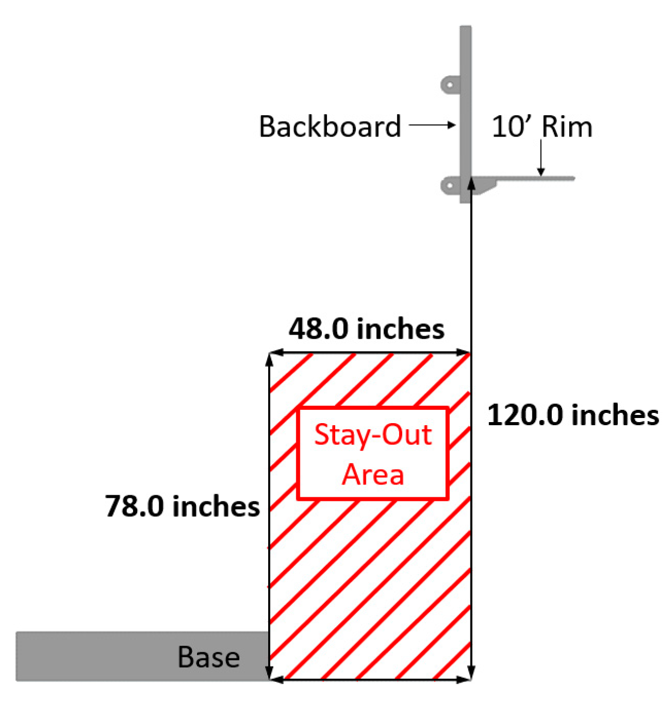
To start the simulation-driven design process of a portable basketball hoop system, certain “given” quantities are established. The rim and backboard have specific dimensions that are not modified. The standard height of the top of the rim is 10 feet above the ground. On professional, college, and high school basketball courts, the distance between the baseline (the out-of-bounds line at the two ends of the court) and front plane of the backboard is 48 inches. The American Society for Testing and Materials (ASTM) standard (ASTM F 1882-06) for the minimum operational height of the bottom of the backboard is 78 inches for a system like this [3]. Consequently, for safety purposes, a clearance area of 48” × 78” is used as the minimum “safe” area between the base, structure, and backboard. Therefore, the starting point for the portable basketball hoop system is a standard sized backboard and rim, with a rim height of 10’ and a 48” × 78” “safe” clearance area between the base, structure, and backboard, as shown in Figure 1.
3.1. Ideation
One of the first challenges when designing the height adjustment mechanism is how to keep the plane of the backboard perpendicular to the ground when adjusting the height while maintaining the 48” × 78” stay-out area. Additionally, when the portable basketball hoop system is folded up in the transporting/storing configuration it must have a height less of than 84 inches (the standard height of a garage door) and ideally a length less than 96 inches.
Creating quick mock-up mechanism geometric bodies and using multibody simulations to quickly examine the apparatus and kinematics is a quick and straightforward process. This process provides important insights into how the structure moves, how the parts are joined, the clearances and interaction between parts, and how compact it is when folded up.
3.2. Material Distribution of Design Spaces
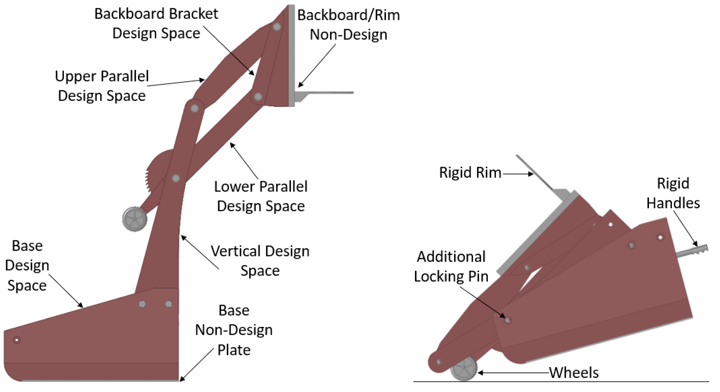
Once the mechanism is designed and the clearances are well understood, the next step is creating design spaces for the topology optimization. Ideally, the design space for each component will envelop all the available volume that the parts can occupy. Having a general idea of how the loads are carried by the structure when generating these design spaces helps to decide how to distribute the material. The multibody simulation provides this insight by extracting forces in the pinned joints and members. This data is used to adjust the design spaces so certain members carrying more load have larger design spaces and therefore more design freedom. Figure 2 shows the design spaces.
3.3. Analysis and Optimization Set-Up
In this case study, all the design spaces are assigned a polycarbonate material. The nondesign rim, pins, and partitioned section of the base are assigned steel with the backboard being glass. All load cases for this structure are conservatively estimated and are simplified to be linear static. Various loads are applied at the end of the rim and the corner of backboard when the rim height is at 10 feet, 9 feet, 8 feet, and 7 feet. Since the backboard and rim are cantilevered out into space and have significant mass, gravity is included in all load cases. Additionally, an acceleration load case is applied when the mechanism is folded up in its transportation configuration to simulate falling off a street curb.
Before discussing the topology optimization set-up, here is a brief description of how topology optimization works. Topology optimization analyzes a design space (the available space for a part) and identifies the best load paths necessary to efficiently support the various load cases. A mathematical approach is used to iteratively optimize the material layout so that the resulting structure meets user-defined design requirements. The end results are typically organic-looking truss structures that are made of only the essential material. The results do not always show exactly how much material is needed for the load paths, but they do show that structure is needed in that location.
The optimization problem is set-up where the objective is to create a structure with the maximum stiffness for all configurations and load cases, while only using a percentage of the available design space. Many other design constraints could be included, but this is a good first step when doing topology optimization and allows the optimizer the most freedom before adding restrictive design constraints. Running the optimization a few times with different percentages of available design space provides good insight into what the critical structural members are.
4. Results
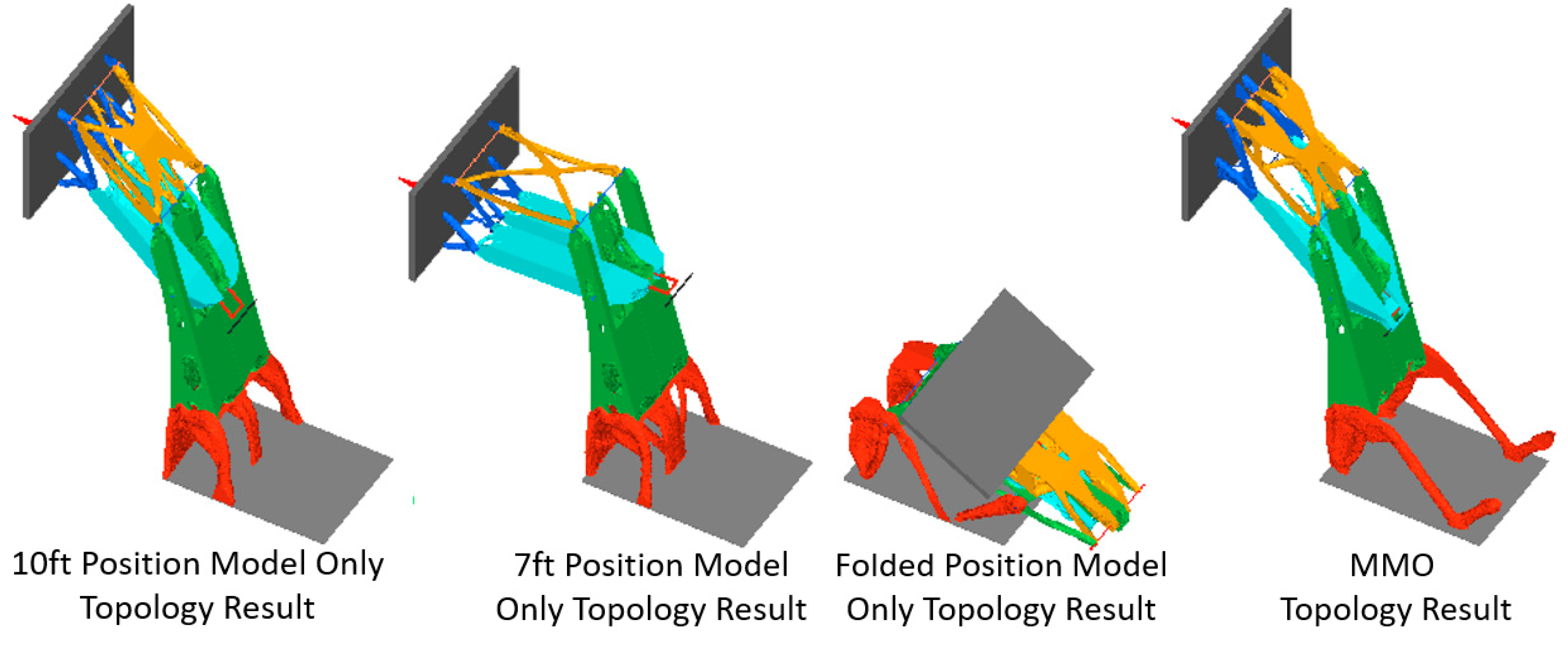
When complex loading or many load cases are applied to a design space it can be very difficult to intuitively determine what the structure should look like to support all the different loads. In this case study, we not only have multiple load cases but also multiple configurations (10 ft, 9 ft, 8 ft, 7 ft, and folded positions) that make it more complex. As such, it is necessary to use multimodel optimization (MMO) so that all loads and configurations are considered when optimizing the structure. To try to understand how each configuration impacts the final MMO results, an optimization analysis of each single configuration model is performed. Since the configuration of the portable basketball hoop system changes how individual parts within the assembly are loaded, the single configuration results are very different from each other as well as from the MMO results. Figure 3 illustrates how the configuration impacts the topology results. As the MMO results show, the optimizer tries to consider all loads and configurations to produce an efficient structure.
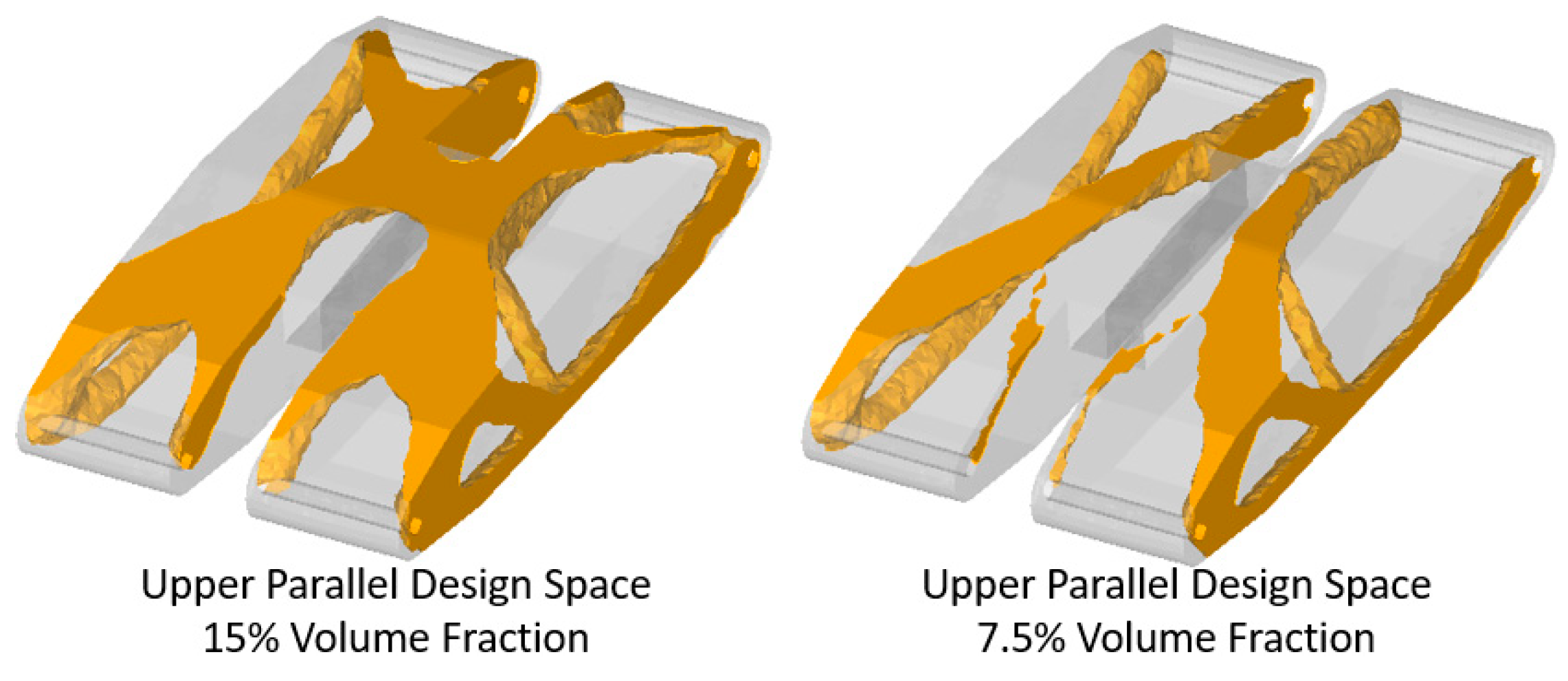
It is good practice to analyze a topology problem with different optimization set-ups. In this case, an adjustment is made to the volume fraction constraint from 15% of the total design space volume to 7.5% of the total design space volume. This provides some insight as to which load paths are critical and where material really needs to be. When comparing the upper parallel design space results, it is clearly seen in Figure 4 that the center connection to the backboard is less critical to a stiff assembly than the outer connection.
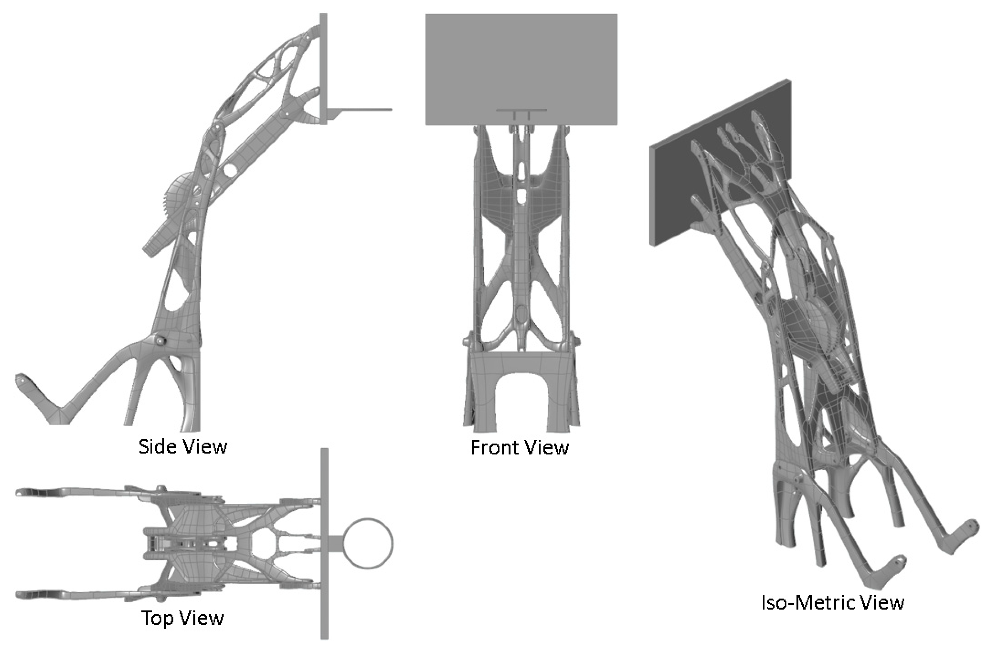
Typically, it is necessary to create an interpreted version of the ragged, organic-looking topology results because they are generally difficult to manufacture. When interpreting the results, it is important to include all dominant load paths and have multiple results to help determine which are more critical than others. Figure 5 shows the initial interpretation of the topology results.
4.1. Verification Analysis
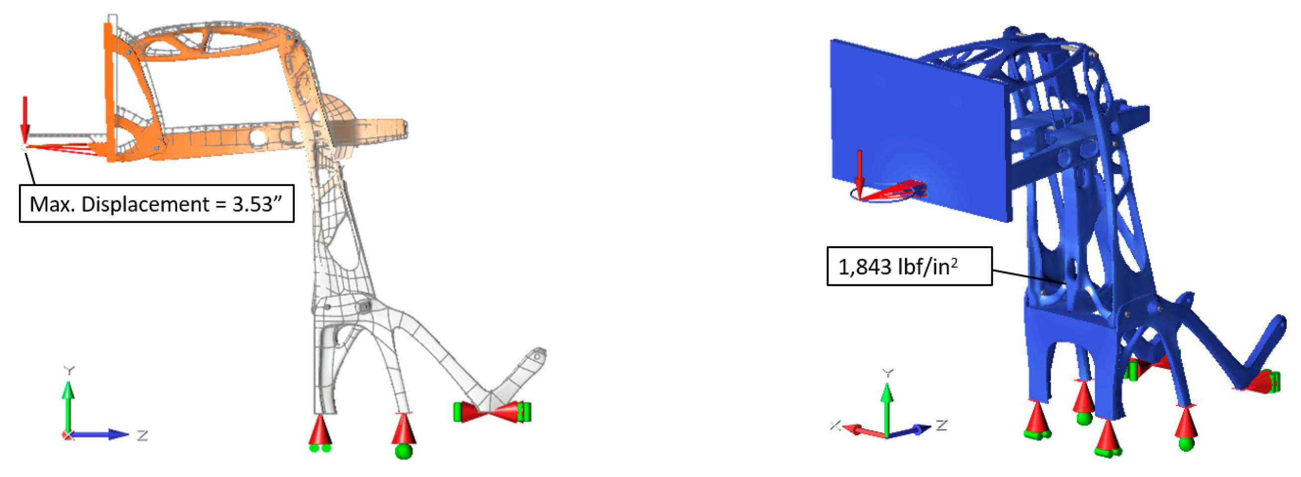
With an interpreted concept design, conducting an initial finite element analysis using the same connections, loads and boundary conditions from the optimization set-up will help guide the next steps in the simulation-driven design process. This analysis provides a first look at the expected displacements and stresses throughout the system. The 7 ft. configuration has the highest deflections and stresses when running this verification analysis. This is the worst loading position, because in this configuration the rim is extended the furthest from the base.
The worst load case in this 7 ft configuration is when a large downward load is applied to the end of the rim. This load caused the polycarbonate assembly to have a maximum displacement of about 3.5 inches. At this time, it is unknown if this amount of deflection is acceptable or not, and additional research and testing are required to compare to similar systems. The stresses in the assembly appear to be well below the yield stress of the polycarbonate. Almost the entire structure has stresses below 2000 psi, and the expected yield stress of the polycarbonate is at least 4000 psi. In some locations where rigid elements are attached to the structure, local artificially high stresses occur. These high stresses are ignored because they are not accurate. Figure 6 shows the displacement and stress contours from the analysis.
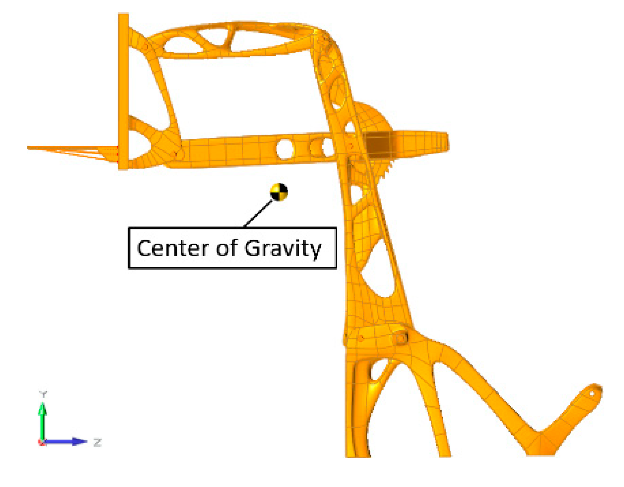
The initial analysis results are promising, but many improvements can still be made as the simulation-driven design process continues. Ideally, the mass of the support structure will be reduced, but additional weight will need to be added to the base to improve the location of the center of gravity which is shown in Figure 7. In all portable basketball hoop system designs, counterweight is added to the base. Often, this is accomplished by having a large hollow cavity in the base than can hold water, sand, or rocks. Future phases will focus on these details of the design as well as more consideration of manufacturing methods and costs. Additional optimization and analysis techniques will be performed to help improve the design and to meet all the design goals.
5. Conclusions and Discussion
This study illustrates the initial steps of a simulation-driven design process. A portable basketball hoop system is used, because several clear design goals and requirements are identified. The design goals of having an adjustable height system that maintains a “safe” 48” × 78” clearance area and can be folded up to be transported and stored in a standard size garage are achieved. The optimization is set-up to take the design spaces that achieve these geometric goals and create the stiffest structure possible for the applied load cases and allotted material.
Additional studies will take this simulation-driven design process to the next steps. These steps will include evaluating the stiffness, durability, and balance of the portable basketball hoop system in its various configurations under the different load cases. Selection of materials, consideration of manufacturability, and evaluation of costs will also be included. Several additional optimization and analysis techniques will need to be executed to help achieve these design goals.
Funding
This research received no external funding.
Conflicts of Interest
The author declares no conflict of interest.
References
- Cline, G. The Benefit of Simulation-Driven Design; Aberdeen Group: Waltham, MA, USA, 2017. [Google Scholar]
- ASTM Standard F1882-06. Standard Specification for Residential Basketball Systems; ASTM International: West Conshohocken, PA, USA, 2006; Available online: www.astm.org.
- O’Connell, L.; Wholesale Sales of Basketball Sports Equipment in the U.S. 2007–2018. Statista.com. Available online: https://www.statista.com/statistics/258582/basketball-sports-equipment-wholesale-sales-in-the-us/ (accessed on 15 October 2019).
Figure 1.
Base and backboard with a rim height of 120” (10 ft.) and “safe” 48” × 78” clearance area.
Figure 1.
Base and backboard with a rim height of 120” (10 ft.) and “safe” 48” × 78” clearance area.

Figure 2.
Portable basketball hoop system design spaces and folded configuration.

Figure 3.
Comparing individual topology optimizations with multimodel optimization (MMO).

Figure 4.
Upper parallel design space—comparing 15% and 7.5% volume fractions.

Figure 5.
Topology interpretation of optimization results.

Figure 6.
7 ft. Configuration displacement (left) and stress (right) contour results.

Figure 7.
Topology interpreted design center of gravity for 7 ft. height configuration (worst case).
Figure 7.
Topology interpreted design center of gravity for 7 ft. height configuration (worst case).


Table 1.
Portable basketball hoop system design goals.
| Design Goal | Software |
|---|---|
| Adjustability (10 ft. to 7 ft. for various ages and skill levels) | Multibody Simulation |
| Playability (stiffness, stability, and mass distribution) | Multimodel Optimization |
| Safety (distance to base, low and rearward cg) | Multibody Simulation |
| Durability and Fatigue Strength | Stress Analysis |
| Compactness and Portability | Multibody Simulation |
| Minimize Cost (minimize and optimize material usage) | Optimization Studies |
| Manufacturability | Optimization Studies |
Publisher’s Note: MDPI stays neutral with regard to jurisdictional claims in published maps and institutional affiliations. |
© 2020 by the author. Licensee MDPI, Basel, Switzerland. This article is an open access article distributed under the terms and conditions of the Creative Commons Attribution (CC BY) license (https://creativecommons.org/licenses/by/4.0/).
Share and Cite
MDPI and ACS Style
Burkhalter, D. Simulation-Driven Design of a Portable Basketball Hoop System. Proceedings 2020, 49, 131. https://doi.org/10.3390/proceedings2020049131
AMA Style
Burkhalter D. Simulation-Driven Design of a Portable Basketball Hoop System. Proceedings. 2020; 49(1):131. https://doi.org/10.3390/proceedings2020049131
Chicago/Turabian StyleBurkhalter, Drew. 2020. "Simulation-Driven Design of a Portable Basketball Hoop System" Proceedings 49, no. 1: 131. https://doi.org/10.3390/proceedings2020049131