The Effect of Instrumentation on Sports Balls During Flight, Exemplified by A Smart AFL Ball: Model and Experiment †


Smart Products Engineering’ Program, Centre for Design Innovation, Swinburne University of Technology, Melbourne, VIC 3122, Australia
†
Presented at the 13th conference of the International Sports Engineering Association, Online,
22–26 June 2020.
Proceedings 2020, 49(1), 102; https://doi.org/10.3390/proceedings2020049102
Published: 15 June 2020
(This article belongs to the Proceedings of The 13th Conference of the International Sports Engineering Association)
Abstract
:Sensors incorporated in a sports ball for data collection can affect the properties of a ball, specifically the spin rate of a ball if the mass distribution (moments of inertia, MOI) is altered. This paper provides a method for assessing the MOIs of a smart ball by means of spin rate data, collected from a gyroscopic sensor. The critical elevation angle of the angular velocity vector defines the separatrix condition, which decides whether the angular velocity vector precesses about the axis with the greatest MOI or with the smallest MOI. The critical elevation angle can be directly determined from the experimental of the angular velocity data, and, together with the ratio of precession speed to angular velocity, applied to calculating the three MOIs. In the smart AFL ball used for the experiments, the critical angle was 13.5°, and the ratio of the two small MOIs was 1.014.
1. Introduction
Smart balls are becoming more popular with the technical improvements of lightweight batteries, miniaturised electronics and long-range wireless data transfer. In addition to electronics considerations, putting instrumentation into a ball can affect the dynamics of the ball:
- -
- The mass of sports balls is regulated and must not be affected by electronic items;
- -
- The mass concentration, i.e., the centre of mass (COM), must remain in its original location, as the ball rotates about the COM during flight, and any COM offset can influence the ball’s aerodynamics;
- -
- The mass distribution, i.e., the moments of inertia (MOI) should not be changed too much, as the MOI affects the rotational behaviour of the ball (spin rate).
It is therefore obvious that any instrumentation of a ball has to be designed carefully and tested extensively. The influence of a changed MOI can be assessed easily if the ball is instrumented with a gyroscopic sensor (gyro). If the spin axis moves (i.e., precesses) with respect to the body coordinate system (BCS, i.e., the ball’s, or more precisely, the gyro sensor’s coordinate system), then either the ball wobbles or the instrumentation has an effect on the MOI. Furthermore, the three MOIs of spherical sports balls are not necessarily identical even without instrumentation. Seams, valves, laces, and material distribution affect the MOIs.
The aim of this paper is to “reverse-engineer” the conditions of a ball’s MOIs from gyro data.
2. Model
The three MOIs about the axes of the BCS are denoted I1, I2, and I3. The instantaneous angular velocity vector (spin axis) is denoted ω1, ω2, and ω3. The intersection lines of the moving (precessing) ω-vector and the ball’s surface are defined by the intersection of two ellipsoids, based on the conservation of two physical properties [1]:
- -
- Conservation of angular momentum, H, defines the angular momentum ellipsoid:
- -
- Conservation of rotational kinetic energy, T, defines the kinetic energy ellipsoid:
The position of the unit ω-vector has to satisfy two conditions, derived from re-arranging Equations (1) and (2):
and
If follows from Equations (3) and (4) that
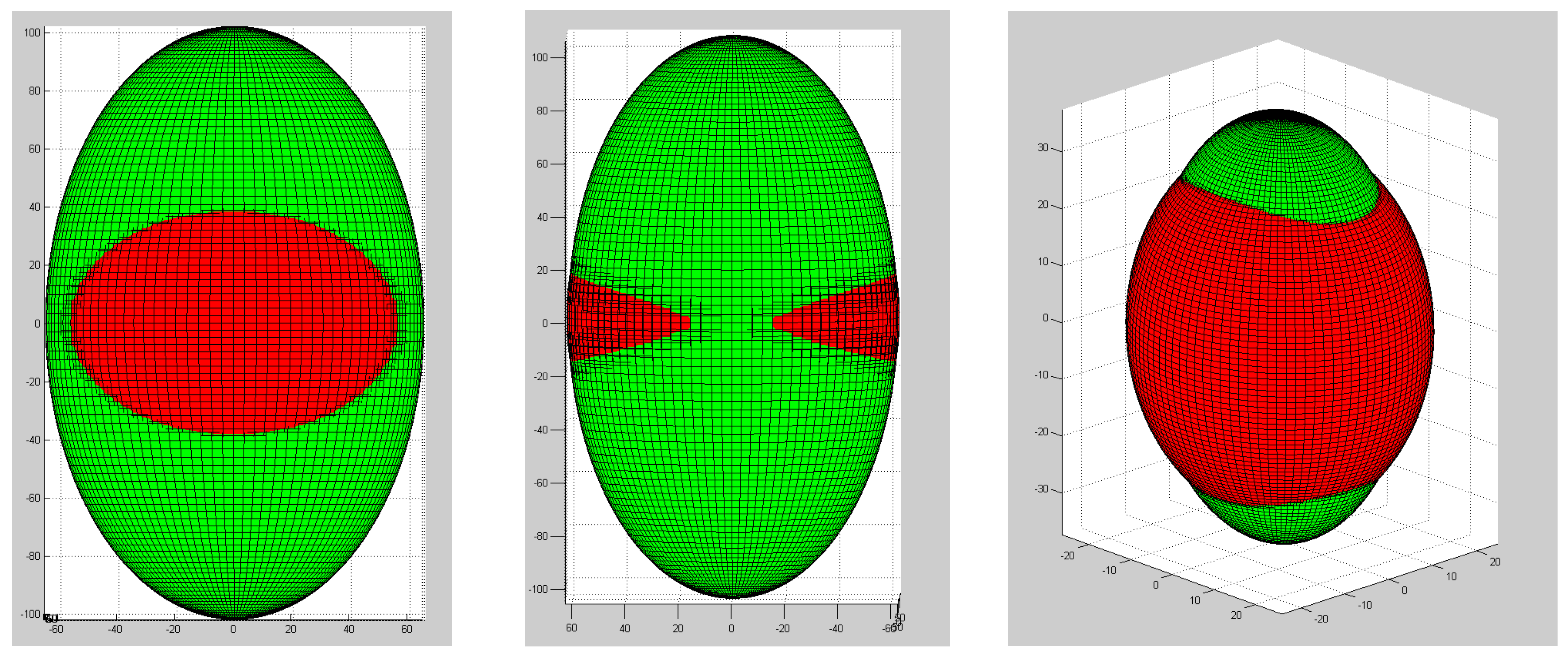
The two ellipsoids (H- and T-) intersect, and the curve of intersection, the so-called polhode, is the path of the angular velocity vector with respect to the BCS. In prolate spheroids (oval balls, such as for rugby, Australian rules football and American football), the ω-vector can rotate about the long (major) axis or about the short (minor) one. Figure 1 exemplifies this behaviour.
Subtracting Equation (3) from Equation (4) and multiplying the result by H2 yields the polhode equation
For real solutions of Equation (6), the three coefficients cannot have the same sign, and
where I* is defined as follows: if I1 > I2 > I3, then I1 ≥ I* ≥ I3.
Projecting the polhode equation, i.e., Equation (6), on the ω1–ω3 plane yields
If I* = I2, then we obtain the separatrix condition
namely, the decision condition that determines whether the ω-vector rotates about the axis with the greatest MOI (I1) or about the axis with the smallest MOI (I3). This principle excludes a stable rotation about the axis with the intermediate MOI (I2)
Equation (9) delivers the critical angle of the ω-vector, namely θcrit, from
and
If the pitch angle of the ω-vector with respect to the ω1–ω2 plane is smaller or greater than θcrit, then the spin axis precesses about the minor (with the greatest MOI I1) or major ball axis (with the smallest MOI I3), respectively.
According to Fuss and Smith [2],
where ωR and Ω are the resultant angular velocity, i.e., √(ω12 + ω22 + ω32), and the precession rate, respectively. The precession rate is the speed at which the ω-vector moves about the minor or major axes. From Equation (12), when plotting Ω/ωR against cos(π/2 – θcrit), the gradient of the regression fit corresponds to (I3 − I1,2)/I1,2 [2]. Ω/ωR and cos(π/2 − θcrit) are determined experimentally from a ball instrumented with a gyro.
Solving Equation (11) for I2 yields
If I1 and I3 are known, or at least the ratio I1/I3 or I3/I1, then I2 can be determined directly, or relative to I1. If θcrit = 0° (ω-vector in ω1–ω2 plane), then Equation (13) reduces to I2 = I1. If θcrit = 90° (ω-vector perpendicular to the ω1–ω2 plane) then tan2θcrit = ∞, and Equation (13) reduces to I2 = I3.
3. Experiment
The experiments were carried out with the smart AFL ball developed by, and described in, Fuss and Smith [2] and Fuss et al. [3]. The angular velocity ω and its three components (ω1, ω2, and ω3.) with respect to the BCS were measured with a gyro. The data from these two references were analysed further. The precessing ω-vectors were reconstructed in 3D in AutoCAD 2000 (Autodesk, San Rafael, CA, USA) with respect to the ball, as well as plotted on an elevation (pitch) vs. azimuth (yaw) diagram (where the yaw angle is the position of the ω-vector projected onto the ω1–ω2 plane, and the pitch angle θ is the included angle between ω-vector and ω1-ω2 plane). The task was to find ω-vectors, precessing very close to, and on either side of, the separatrix condition, in order to determine θcrit. From Equation (13), I2 was estimated and compared to I1.
4. Results
Figure 2 shows ω-vectors at different θ-angles, precessing about the major axis of the ball (Figure 2a–c) and the minor axis (Figure 2d).
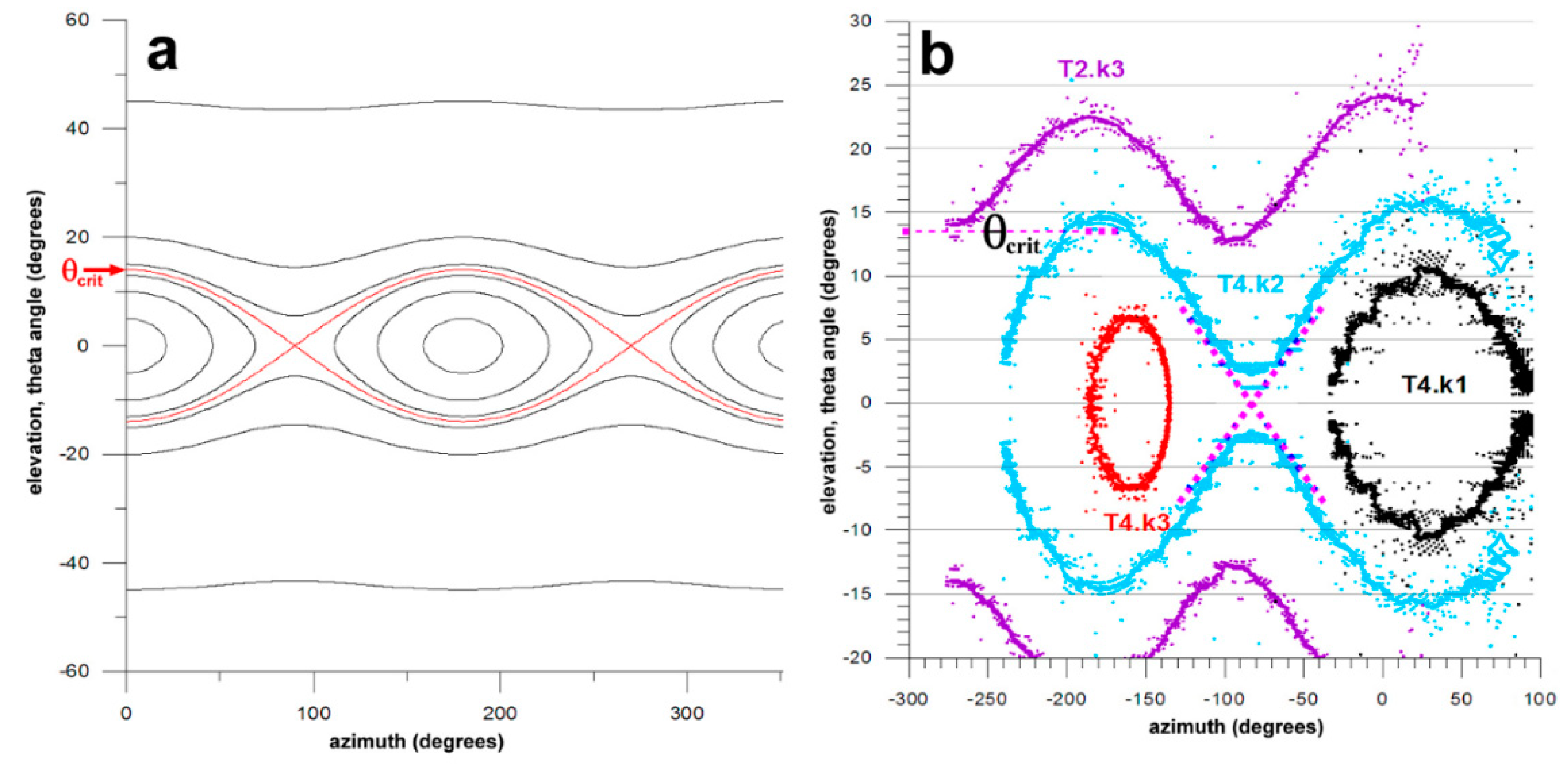
Figure 3 explains how θcrit was determined, which was approximately 13.5°. From Fuss and Smith [2], by applying Equation (12), (I3 − I1,2)/I1,2 was 0.42, resulting in I1,2/I3 of 1.724. When normalizing the MOIs to I3, then I3 = 1, and I1,2 = 1.724. Yet, if θcrit > 0°, then I1 ≠ I2. Finding I2 from Equation (13), considering that I1,2 = (I1 + I2)/2, delivers the following results: I1 = 1.736, I2 = 1.712, and I1/I2 = 1.014. The latter ratio teaches that I1 is only 1.4% greater than I2.
5. Discussion
There are other ways of determining the MOI of an object about a specific axis, such as the pendulum method. The method used in this study, however, has the advantage that the behaviour of the ω-vector changes immediately when crossing the separatrix polhode.
It has to be borne in mind that the axes, about which an object spins and its ω-vector precesses, are not identical. In the ball shown in Figure 2c, the ω-vector precesses about the major axis while the ball spins about the minor axes with a slightly elevated and tilted ω-vector. The latter fact defines the kick as a drop punt. Thus, the critical angle θcrit cannot be used for classification of, and distinction between, drop punts and torpedo punts.
That I1 and I2 turned out to be different, even only slightly, is an effect of the instrumentation as well as of the valve. The instrumentation was protected by an electronics box with a rectangular cross section such that I1 > I2. The valve alone (two semi-cylindrical pieces of rubber) had the same effect (I1 > I2.). Nevertheless, even if that small difference in MOI can be ignored mechanically, it does make a difference in terms of the ω-vector’s behaviour. The latter is characterized by changing the axis about which it precesses. These principles should be known to researchers and practitioners dealing with smart balls, in order to interpret the sensor data correctly.
Acknowledgments
No funds were received for conducting this study, nor for covering the costs to publish in open access.
Conflicts of Interest
The author declares no conflict of interest.
References
- Ginsberg, J.H. Engineering Dynamics; Cambridge University Press: Cambridge, UK, 2008; Volume 10. [Google Scholar]
- Fuss, F.K.; Smith, M.R. Development of a smart oval ball for assessment of angular flight dynamics and precision of kick execution. Sports Tech. 2011, 4, 151–158. [Google Scholar] [CrossRef]
- Fuss, F.K.; Smith, M.R.; Leali, F. Kick precision and spin rate in drop and torpedo punts. Procedia Eng. 2013, 60, 448–452. [Google Scholar] [CrossRef]
Figure 1.
Angular momentum and kinetic energy ellipsoids of a prolate spheroid. The two left subfigures show the polhode (intersection of the two ellipsoids) about a minor axis of the prolate spheroid, in front view and side view. Note that there are two solutions and the ω-vector follows either the front or back polhode. If the two solutions merge, then the ω-vector follows either the top or bottom polhode (counterclockwise or clockwise spin) shown in the right subfigure.

Figure 2.
ω-vectors (colour-coded) projected on the surface of an AFL ball and the corresponding ellipsoids: (a) almost-perfect torpedo punt, the ball spins about the major axis of the ball and ω precesses about the major axis; (b) imperfect torpedo punt, the ball spins about the major axis and ω precesses about the major axis; (c) imperfect drop punt, the ball spins about the minor axis of the ball and ω precesses about the major axis; (d) almost-perfect drop punt, the ball spins about the minor axis of the ball and ω precesses about the minor axis.

Figure 3.
Elevation angle (pitch) of the ω-vector vs. azimuth angle (yaw) diagram (where the yaw angle is the position of the ω-vector in the ω1–ω2 plane, and the pitch angle ω is the included angle between ω-vector and ω1–ω2 plane); (a) polhode diagram for θcrit of 13.5° (the red polhode indicates the separatrix condition); (b) experimental data on four kicks (the data were mirrored about θ = 0°); the crossed dashed lines indicate the separatrix condition; θcrit ~ 13.5°.

Publisher’s Note: MDPI stays neutral with regard to jurisdictional claims in published maps and institutional affiliations. |
© 2020 by the author. Licensee MDPI, Basel, Switzerland. This article is an open access article distributed under the terms and conditions of the Creative Commons Attribution (CC BY) license (https://creativecommons.org/licenses/by/4.0/).
Share and Cite
MDPI and ACS Style
Fuss, F.K. The Effect of Instrumentation on Sports Balls During Flight, Exemplified by A Smart AFL Ball: Model and Experiment. Proceedings 2020, 49, 102. https://doi.org/10.3390/proceedings2020049102
AMA Style
Fuss FK. The Effect of Instrumentation on Sports Balls During Flight, Exemplified by A Smart AFL Ball: Model and Experiment. Proceedings. 2020; 49(1):102. https://doi.org/10.3390/proceedings2020049102
Chicago/Turabian StyleFuss, Franz Konstantin. 2020. "The Effect of Instrumentation on Sports Balls During Flight, Exemplified by A Smart AFL Ball: Model and Experiment" Proceedings 49, no. 1: 102. https://doi.org/10.3390/proceedings2020049102