Mass and Heat Integration in Ethanol Production Mills for Enhanced Process Efficiency and Exergy-Based Renewability Performance


1
School of Chemical Engineering, Laboratory of Optimization, Design and Advanced Process Control-LOPCA, University of Campinas, Campinas 13083-852, Brazil
2
Department of Biotechnology, Faculty of Applied Sciences, Delft University of Technology, 2629 HZ Delft, The Netherlands
*
Author to whom correspondence should be addressed.
Processes 2019, 7(10), 670; https://doi.org/10.3390/pr7100670
Submission received: 30 June 2019
/
Revised: 16 September 2019
/
Accepted: 20 September 2019
/
Published: 27 September 2019
(This article belongs to the Special Issue Bioenergy Systems, Material Management, and Sustainability)
Abstract
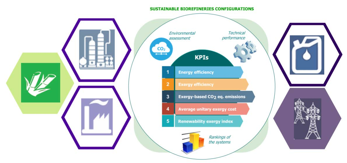
:This paper presents the process design and assessment of a sugarcane-based ethanol production system that combines the usage of both mass and heat integration (pinch analysis) strategies to enhance the process efficiency and renewability performance. Three configurations were analyzed: (i) Base case: traditional ethanol production (1G); (ii) mass-integrated (1G2G); and (iii) mass and heat-integrated system (1G2G-HI). The overall assessment of these systems was based on complementary approaches such as mass and mass–heat integration, energy and exergy analysis, exergy-based greenhouse gas (GHG) emissions, and renewability exergy criteria. The performances of the three cases were assessed through five key performance indicators (KIPs) divided into two groups: one is related to process performance, namely, energy efficiency, exergy efficiency, and average unitary exergy cost (AUEC), and the other one is associated to environmental performance i.e., exergy-based CO2-equation emissions and renewability exergy index. Results showed a higher exergy efficiency of 50% and the lowest AUEC of all the systems (1.61 kJ/kJ) for 1G2G-HI. Furthermore, the destroyed exergy in 1G2G-HI was lower by 7% and 9% in comparison to the 1G and 1G2G cases, respectively. Regarding the exergy-based GHG emissions and renewability performance (λindex), the 1G2G-HI case presented the lowest impacts in terms of the CO2-equivalent emissions (94.10 gCO2-eq/MJ products), while λindex was found to be environmentally unfavorable (λ = 0.77). However, λindex became favorable (λ > 1) when the useful exergy of the byproducts was considered.

1. Introduction
Increasing global energy demand combined with global warming effects associated with greenhouse gas (GHG) emissions have accentuated the need to find more sustainable and environmentally friendly energy sources to replace fossil fuels [1]. In this context, biofuels could contribute as a player in achieving environmental goals and energy demand. In particular ethanol is the most important biofuel, with USA and Brazil as the largest producers worldwide with an annual production (by 2018) of 58 billion liters (primarily from cornstarch) and 28 billion liters (primarily from sugarcane), respectively [2].
One of the key factors to implement and consolidate a more efficient process in the biofuel sector is related to technological improvements in conventional biorefinery systems (i.e., mass and energy integration). In the particular case of ethanol production, the integration of second-generation processes into traditional ethanol mills (1G2G biorefineries) could increase its supply potential and process efficiency due to the use of lignocellulosic materials into the process, which are nonfood crops, abundant, and cheaper than first-generation feedstocks like sugarcane or corn [3]. However, to understand to what extended these processes could potentially be improved, mass and heat integration strategies are needed along with the development of suitable process performance indicators and renewability metrics.
The multi-faceted nature of the assessments has led to the derivation of various indicators such as technical, economic, social, and environmental [4]. A set of energy-based key performance indicators (KPIs) have been proposed in literature, often with similarities or discrepancies (material efficiency, total energy input, energy intensity, energy efficiency). Nevertheless, they are still useful if applied as complementary measures considering that they depend on the specific context, therefore conclusions on process performance should not be generalized [3]. These indicators could present some biases and provide ambiguous results in certain conditions. Hence, decision-support systems on exergy basis and traditional cost or economic analysis have also been developed in order to carry out multidimensional analyses. Magnanelli et al. [5] presented exergy-based KPIs for industrial practices. This work outlined the advantages and limitations of the reviewed indicators aiming their use towards industry. The selected case studies were an offshore oil and gas processing plant, a gas-fired combined cycle power plant, and a silicon production process. Meanwhile, Stougie et al. [6] assessed the environmental, economic, and exergetic sustainability of the five power generation systems (i.e., coal-fired power plant, coal-fired power plant with carbon capture and storage, biomass-fired power plant, offshore wind farm, and photovoltaic park) using the total cumulative exergy loss (TCExL) as an indicator. This method was developed with the aim of taking into account many aspects of sustainability and all exergy losses caused by a technological system during its life cycle. Posada et al. [7] carried out a conceptual design of sustainable integrated microalgae-based biorefineries through a parametric analysis of energy use, GHG emissions, and techno-economic assessment. This study showed possible processing pathways and important technologies for industrial scale microalgae valorization, as well as identified microalgae-based biorefinery arrangements, presenting the best configuration regarding environmental, technical, and economic performance.
Systems design, process performance, and economic analysis had been devoted to integrating second-generation technology into first-generation plants (1G2G integrated systems). For instance, Santos et al. [8] presented a techno-economic analysis and an environmental assessment of the whole production chain (biomass production, sugar extraction, biomass pretreatment, sugars fermentation, and products recovery and purification) of an integrated 1G2G sugarcane-based biorefinery for biojet fuel production. Albarelli et al. [9] analyzed a scenario related to the integration of the autonomous distillery with the second-generation ethanol production using the bagasse pith (P-fraction) as feedstock. These authors accomplished a heat integration evaluation, analyzing the role of product diversification in the economic viability of 2G processes. Whereas Palacios et al. [10] investigated the exergetic performance and exergetic cost of the ethanol production through the enzymatic hydrolysis of sugarcane bagasse integrated into the conventional process. Three levels of solids content in the hydrolysis reactor, 5%, 8%, and 10%, were considered using evaporation and membrane systems. They found that the highest ethanol yield was achieved by means of the membrane system with a solid content of 5% in the hydrolysis reactor, which resulted in an increase of 22% over conventional distilleries. Dias et al. [11] performed a process simulation of an integrated production of first- and second-generation ethanol from sugarcane, including technical, economic, and environmental aspects. The second-generation ethanol production adopted steam explosion as pretreatment and enzymatic hydrolysis of sugarcane bagasse. These authors established that 1G2G integrated processes present advantages over stand-alone 2G ethanol production from sugarcane when both technical and economic perspectives are considered, while the environmental performance is method and allocation criteria dependent.
Although some studies have addressed the thermodynamic assessment, there is not a systematic method reported yet to understand the renewability of mass and heat-integrated systems that take into account exergy-based GHG emissions, the exergy analysis, and the mass–heat integration. Thus, three sugarcane ethanol biorefineries process with different levels of integration were here analyzed: (i) base-case: traditional ethanol plant (1G) as reference system; (ii) mass-integrated (1G2G): increased ethanol production and surplus electricity by introducing the pretreatment and hydrolysis processes; and (iii) mass and heat integration (1G2G-HI) of the first- and second-generation plant. The overall assessment of these systems was based on complementary approaches, i.e., mass and mass–heat integration, energy and exergy analysis, exergy-based GHG emissions, and renewability exergy criteria. Furthermore, the comparison metrics used were: global energy and exergy efficiency, average unitary exergy cost, specific CO2-equivalent emissions in exergetic base, and renewability exergy index, respectively, in order to assess these biochemical biorefineries.
2. Process Description of Ethanol Production
2.1. Battery Limits
The control volumes adopted in this work include a sugarcane distillery (first generation-1G) and an integrated first and second-generation ethanol process (1G2G biochemical plant). An exergy-based assessment focuses on the sugarcane ethanol process chain, as shown in Figure 1 and as described below.
2.2. First-Generation (1G) Ethanol Process
Extraction System: In this step, sugarcane bagasse is obtained, which represents a byproduct in suitable condition for burning in the boilers. Then, two kinds of devices are used to perform this operation: mills and diffusers. A comparison of milling and diffusion systems from sugarcane is presented in Palacios-Bereche et al. [12].
- Juice treatment: The sugar juice is heated up from 30 to 70 °C, and subsequently processed with lime (CaO) to precipitate impurities or sludge that are taken out by filtration. The clear juice is further heated up to 105 °C and flashed to eliminate water. This clarified and concentrated juice is adequate for use in the fermentation process [13].
- Fermentation: In this stage, yeast or other microorganisms are used to produce ethanol (and other organic compounds as byproducts). The ethanol recovery from the fermentation gases is performed by an absorption column [14].
- Distillation: Initially, the fermentation broth is centrifuged to take out yeast and the other suspended substances. A clarified broth containing around 7–12 v/v% ethanol is obtained. Subsequently, distillation is applied to remove water, remaining solids, and lighter organics to produce an aqueous solution containing 90–95 v/v% ethanol [13].
- Dehydration: Ethanol 95 v/v% is dehydrated to fuel-grade anhydrous ethanol (>99 v/v%) by utilizing molecular sieves in a pressure swing adsorption (PSA) process. In contrast with azeotropic distillation, PSA saves roughly 840 kJ of energy per liter of ethanol produced [13].
- Combined heat and power (CHP): In the cogeneration system, bagasse coming from the extraction step is sent to the utility plant to produce steam, which is used in backpressure steam turbines. Equipment responsible for matching the electromechanical demands of the mill.
2.3. Second-Generation (2G) Ethanol Process
Sugarcane bagasse and straw (lignocellulose materials) could be used as feedstock for ethanol production through pretreatment and hydrolysis processes [15], which are the main technologies of the second-generation ethanol production.
Regarding the biomass pretreatment processes, hot water and steam explosion are commonly used in the biofuel industry. Hot water dissolves biomass and removes part of lignin and hemicellulose. Whereas in the steam explosion, high-pressure steam rapidly heats biomass to promote hemicellulose hydrolysis, followed by rapid pressure release [16]. Reaction time, temperature, particle size, and moisture content are considered the important variables in the biomass pretreatment technologies.
In the pretreatment process, a fraction of hemicellulose (represented by xylan) is transformed into xylose and xylose oligomers. A diffuser is used to separate a liquid stream of the pretreated material, named C5 liquor. Thus, C5 liquor undergoes a neutralization treatment for pH correction prior to deoligomerization and fermentation of C5 liquor to ethanol. The solid fraction of the pretreated material is directed to the enzymatic hydrolysis reactor [17]. Enzymatic hydrolysis is an important step of the biochemical route since it impacts the overall process performance and costs in the production of fermentable sugars. Subsequently, the C5 and C6 fermented streams (resulting in a clarified broth from fermentation, known as beer or wine) are mixed and directed to distillation columns as depicted in Figure 1. Similar to 1G autonomous distillery, ethanol dehydration is conducted using molecular sieves. More details of the second-generation process descriptions can be found elsewhere [17,18].
3. Methodology
To understand the effects of two levels of process integration (mass and heat), the 1G and 2G ethanol production process were conceptually designed and simulated. Then, the obtained mass and energy flows were used to identify opportunities for heat integration by applying the pinch methodology. Finally, three process performance indicators (i.e., energy efficiency, exergy efficiency, and the average unitary exergy cost) and two exergy-based GHG emissions and renewability performance indicators (i.e., specific CO2 equivalent emissions and renewability exergy index) were calculated and compared to the two levels of integration and with respect to the autonomous ethanol production process. The flow diagram of the conceptual process design, simulation, and assessment methodologies is shown in Figure 2.
3.1. Process Simulation
Technical data for a standard sugarcane biorefinery processing 4 million tons of sugarcane per season, with a recovery rate of 50% of straw (30 w/w% moisture content) were considered [19]. The feedstock composition adopted in this study is presented in Appendix A Section (Table A1 and Table A2). Simulations were carried out using Aspen Plus software V8.8 [20]. Firstly, mass and energy balances were determined for each process. The simulation procedure includes flow sheeting, selection of a suitable thermodynamic model, and the specification of appropriate operating conditions. Cellulose, hemicellulose, and lignin are defined as user-defined substances to allow the calculation of thermodynamic physical properties like boiling points, molecular weights, etc. The component properties of the lignocellulosic material were retrieved from the biofuel databank developed by NREL [21]. For this study, due to the presence of vapor–liquid components such as ethanol and steam, the non-random two-liquid (NRTL) model was used to predict the activity coefficients of the components in the liquid phase. The thermodynamic properties of the vapor phase were estimated based on Redlich–Kwong equation of state for non-ideal conditions such as operation under moderate pressures (around 10 bar) or a high concentration of sugar. The Hayden O’Connell (NRTL-HOC) equation was utilized for vapor-phase calculations when the concentration of acetic acid and other carboxylic acids was significant, for instance, on fermentation and distillation units. For steam turbine power generation, STEAM-TA properties were taken into account.
3.1.1. Simulation of the First-Generation (1G) Ethanol Process
Detailed parameters and processing conditions used for the simulation of the 1G ethanol process are included in Table A4 and Table A5. In addition, a simplified flowsheet of the ethanol production process implemented in Aspen Plus is given in Figure A1 of the Appendix A Section, which considers the following stages:
- Cleaning of sugarcane and extraction of sugars: sugarcane is prepared for extraction through shredders and then juice is extracted in the mills. For the simulations, a dry-cleaning system using air was considered.
- Juice treatment: following extraction, sugarcane juice suffers a physical treatment including cyclones and filters for eliminating solids and insoluble contaminants. Soluble contaminants are eliminated at the chemical treatment process by adding some reactants such as phosphoric acid, hydrated lime.
- Juice concentration: treated juice is concentrated to reach an appropriate sugar concentration (approx. 18 w/w%) for the fermentation process [22]. The concentration of treated juice takes place in a multiple effect evaporation (MEE) system in order being mixed with the must of sugarcane juice for the integration of hydrolysis process to traditional plants of ethanol.
- Fermentation: in this step the conversion of sugars into ethanol occurs. The process is simulated considering the Melle–Boinot configuration based on [9,10,23]. The major parameters and fermentation reactions are shown in Appendix A Section.
- Distillation and dehydration: The produced ethanol is recovered from the beer in the distillation area. Hydrated ethanol (93 w/w%) was obtained in the distillation process as a result of stripping (A–A1–D) and rectification columns, B–B1, as described in Figure A1. Beer is fed in column A1 and the three major output streams are the volatile impurities, which are removed in the top of column D; vinasse, the bottom product from column A; and phlegm, a stream rich in ethanol, which follows to the rectification columns. From the bottom of column B1, a closely pure water stream is removed, named phlegmasse; hydrated ethanol is obtained on top of column B; and a side stream, containing most of the higher alcohols, is removed from Col. B as well. Adsorption by means of molecular sieves was used to dehydrate the azeotropic solution from Col. B to obtain 99.6 w/w% anhydrous ethanol [17].
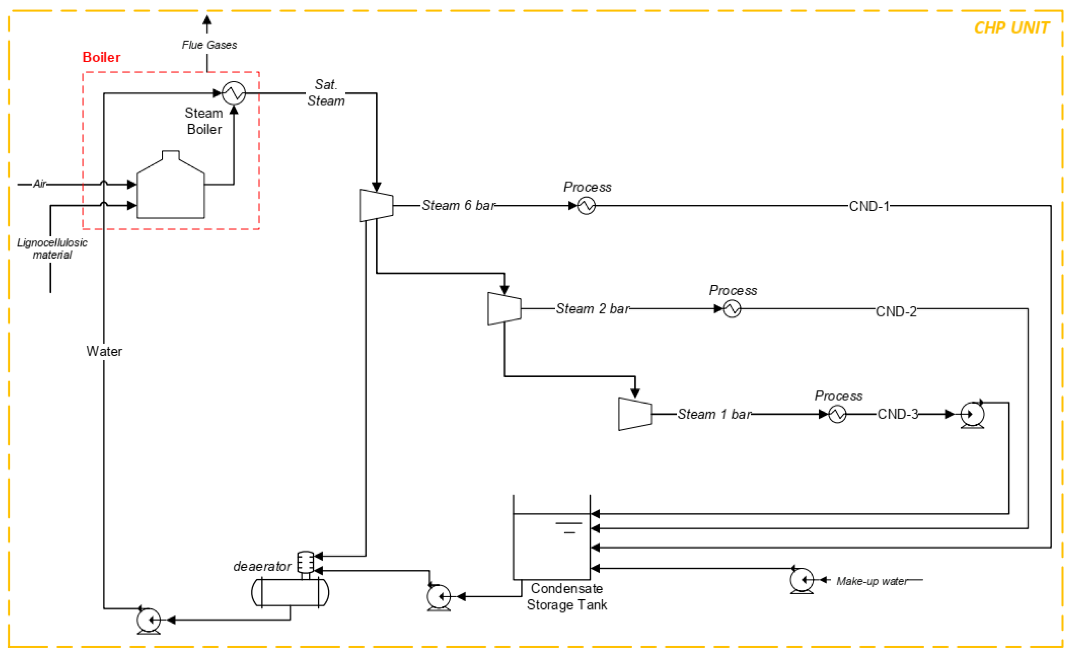
- Combined Heat and Power (CHP): A steam cycle operating with superheated steam at 485 °C and 65 bar with backpressure steam turbines is here considered for this process unit. This configuration was used to generate only the necessary process steam, allowing a surplus of bagasse, which could be used in an enzymatic hydrolysis process [24]. The bagasse with 50 w/w% of moisture content was adopted as fuel for the cogeneration unit. Moreover, the combustion reactions in the boiler section were here studied as indicated by NREL [21,25]. The process flow diagram of the CHP unit is described in Figure A3 and the parameters of the cogeneration system, including the chemical reactions of the boiler section, are given in Table A6.
3.1.2. Simulation of the Second-Generation (2G) Ethanol Process
The second-generation process was based on the steam explosion pretreatment technology followed by enzymatic hydrolysis. Data was gathered from the optimal conditions reported by Carrasco et al. [26]. Thus, considered in the pretreatment reactor was the formation of xylose (C5H10O5) and acetic acid (C2H4O2) from hemicelluloses (C5H8O4), the formation of furfural from xylose, and the formation of glucose (C6H12O6) from cellulose (C6H10O5). The hydrolysis steps are performed at 50 °C with a residence time of 24 h and a cellulase concentration of 15 FPU/g of biomass (enzyme activity 65 FPU/g) [26]. The cellulosic hydrolysate (C6 liquor) is concentrated to achieve appropriate glucose content for the fermentation process. After the concentration, the hydrolysate is mixed with must of sugarcane juice and added to the fermentation process. Moreover, steam for pretreatment is supplied from the cogeneration system.
Glucose hydrolysate is preheated with steam flash recuperated from the pretreatment decompression before undergoing the evaporation system, which operates with steam at 2.5 bar. A five-stage evaporation system was adopted to reduce the steam consumption. In the simulation, each stage of the evaporation system was considered by two unit operations: a heat exchanger and a flash separator [24]. It was assumed that the condensate of exhaust steam from this evaporation system returns to the cogeneration unit and a solid content of 10% in the hydrolysis reactor. Detailed processing conditions, flowsheets (Figure A2) and chemical reactions adopted for the simulation of the 2G ethanol process are included in the Appendix A Section.
3.2. Heat Integration through Pinch Analysis
Process integration is a key aspect of the design of sustainable industries. According to Foo et al. [27], pinch analysis is an insight-based framework that uses a two-step strategy comprised of targeting and system design. Targeting may be done using a variety of graphical or algebraic methods to determine the optimal thermodynamically feasible extent of energy and material recovery in a system, the net utility requirements from external sources, and the system bottleneck. Process integration is associated with the system design (heat integration) and the pinch point, that is, the point where driving forces (related to heat transfer) are at the minimum feasible value [27].
Thus, after defining the maximum heat recovery potential between hot and cold streams and considering a minimum temperature difference approach (ΔTmin), the optimal thermal process integration is obtained. Detailed steps for the pinch design methodology can be found elsewhere [28,29]. The pinch method was here adopted to determinate the minimal energy consumption targets after doing process design and simulation. The ΔTmin considered in this study for the process streams was 10 °C, except for flow streams coming from evaporation systems, where 4 °C was selected [24,30]. Once these values are common practice in the sugar and ethanol plants, focus is on thermal integration implementation. The thermodynamic parameters (data extraction) of the streams selected for heat integration are included in Table A9 (Appendix A Section).
3.3. Exergy Analysis
The exergy approach, which combines the First and Second Law of Thermodynamics is applied to assess the performance of the two levels of integration in the ethanol production process. Exergy analysis is an effective tool for evaluating the quality and quantity of a resource, as it represents the maximum of the quantity of the resource that can be converted into work, given the prevailing environmental conditions [31]. In this study, the chemical (BCH) and physical (BPH) exergies are considered in the assessment due to the physico-chemical processes involved. The physical exergy of a stream can be calculated based on thermodynamic properties obtained, such as enthalpy and entropy obtained after process simulation in Aspen Plus software of each stream within each unit. The BPH was determined according to Equation (1).
where H, T, S represents enthalpy, temperature, and entropy, respectively. The subscript 0 means the reference environmental state (25 °C, 1 atm).
On the other hand, chemical exergy is defined as the energy available to do work when the substance undergoes a reversible process from the restricted reference state to a thermodynamically dead state in which the system is in a complete thermodynamic equilibrium (thermal, pressure, and chemical) [31]. Conceptually, then, chemical exergy quantifies the value of a chemical substance, or compound, as measured against a selected reference environment [32]. Equation (2) defines the chemical exergy:
where nmix is the total amount of moles of all constituents in a mixture, xi is the mole fraction of component i in the mixture, and the term is the standard chemical exergy. In this work, the influence of activity coefficient (Ὑ) was evaluated for each compound, allowing us to observe that it provides values close to one.
The exergies of ethanol–water solutions, such as hydrated and anhydrous ethanol, were determined following the procedure reported in Ensinas and Nebra [33]. For the calculation of the chemical exergies of the resulting clarified broth (beer or wine), vinasse and phlegmasse from distillation columns and pentose liquor attained by hydrolysis were considered as ideal solutions. Therefore, molar fraction was used instead of activity since these streams are very diluted solutions and activity data for the main components in fermentation and pretreatment steps such as aconitic acid-C6H6O6, glycerol-C3H8O3, furfural-C5H4O2, xylose-C5H10O5, yeast, and enzymes, which are not available in literature. Moreover, the exergy of dissolution is significantly low in comparison to the standard chemical exergy of the pure components [10].
The standard chemical exergies for various compounds are found in the literature [31,34]; however, it can also be calculated based on correlation functions. The values of the compounds and the correlation used in the exergy analysis were included in Table A12.
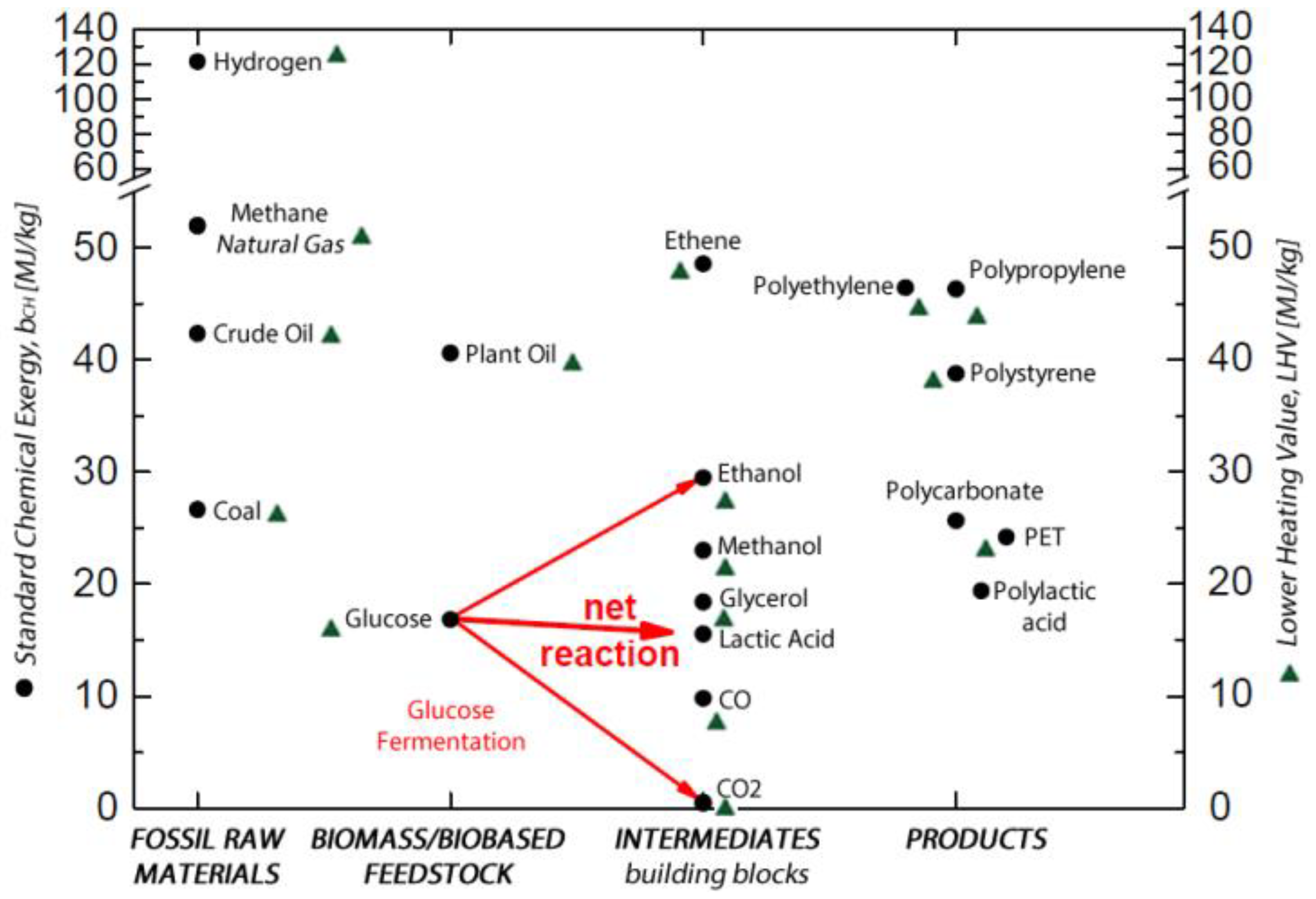
It is noted that the specific chemical exergies, in reference conditions of temperature and pressure (T0 and P0), are usually close to its lower heating value (LHV) for fuels, as shown in the relation between bCH and LHV given in Figure 3. Hence, the chemical exergy of a substance can be evaluated using correlations (φ) based on the composition, as presented by Szargut et al. [31] and Kotas [34], such as:
The technological comparisons carried out in Section 4 are founded on the exergy efficiency calculations of each system. First, the exergy of the products (Bp) and the inputs (Bi) are determined. Table A13 (Appendix A Section) presents the bch and LHV values for several fossils and bio-based raw materials. This table is used in the benchmark of biorefinery configurations (Section 4.3), once it reports the exergy values for sugarcane (SC), SC bagasse, straw, and sugar.
Afterward, the exergy balance for an integrated ethanol sugar plant was applied to calculate the irreversibility (I) of the processes, according to Equation (4).
3.4. Key Performance Indicators (KPIs)
A set of complementary performance indicators were selected for assessing biorefinery sustainability based on thermodynamic performance and environmental impacts (see Table 1). These metrics are suitable for comparison of biorefinery alternatives and identification of the processing pathways over fossil-based configurations.
3.4.1. Average Unitary Exergy Cost
Exergetic cost is a conservative value accounting for the external exergy that is necessary to make an exergy flow available within a specific productive process [36]. Thus, the AUEC is a measure of the irreversibilities, which occur during the upstream processes in order to form a given exergy stream. Therefore, higher irreversibilities result in a higher unit exergy cost. It is important to highlight that the exergy cost allows a closer view of the contribution of each product to plant efficiency, allowing for the allocation of losses between products based on a thermodynamic premise.
The unit exergy cost c (kJ/kJ) of the ethanol and the electricity production is calculated as the inverse of the exergy efficiency of the ethanol process and cogeneration unit, respectively, given in the Appendix A Section (Figure A4). Furthermore, the exergy assessment (Figure A5) and the exergy efficiency definitions of the cogeneration unit, the ethanol process, and the overall process are reported in Table A10.
3.4.2. Exergy-Based CO2 Equivalent Emissions
This work focuses on the environmental impact assessment throughout the industrial processing (sugarcane ethanol process chain) with quantification of the CO2 emission effects in the first generation process and integrated 1G2G ethanol process (also with mass and heat integration), according to the system boundaries defined in Figure 1.
Carbon dioxide emissions are based on the CO2 equivalent emissions of global warming potential (GWP) reported by the Intergovernmental Panel on Climate Change (IPCC) [37]. The values are calculated as a weighted sum of the mass flow rates of the greenhouse gas components using as weights the 100-year GWP [20]. Consequently, the balance of each unit operation block displays the CO2 equivalents of the combined feed streams, combined product streams, and net production in the simulation results. In the case of the comparison of ethanol producing scenarios, boundaries were set from cradle to gate and the functional unit defined as one liter of ethanol.
Life cycle inventory (LCI) data adopted in this study is reported in Table A11. LCI data for the sugarcane production were developed by Brazilian Bioethanol Science and Technology Laboratory (CTBE). Details on the methodological approach of the model and the assumptions considered for the definition of the inventory can be found elsewhere [38,39]. Since the focus of this study is placed on the comparison of technological routes (industrial processes stage), main parameters were assumed as average values representative for sugarcane production in São Paulo state, which is the largest producer of sugarcane and ethanol in Brazil.
3.4.3. Renewability Exergy Index
The renewability concept has mainly been associated with mass and energy efficiencies without taking into account the reduction of the energy quality related to conversion processes. Thus, the renewability exergy index (λ) was proposed, founded on the concept of reversible processes to develop the renewability analysis in a rational basis by thermodynamic parameters [40].
Equation (9) shows the renewability exergy index; where, Bproduct denotes the net exergy associated with the products and/or byproducts, Bfossil is the nonrenewable exergy consumed in the production processes chain, which denotes the exergy associated with the chemical and biochemical compounds specified in Table A14. Moreover, Bdestroyed is the exergy destroyed inside the system, punishing the process for its inefficiencies. Bdeactivation accounts for exergy required for passing the streams leaving the system, considered as wastes, to not harm environmental conditions. Bdisposal is the exergy related to waste disposal of the process, Bemissions is the exergy of wastes that are not treated or deactivated. Thus, according to Oliveira Jr. [40], depending on the value of the renewability exergy index, it indicates that: (i) processes with 0 ≤ λ < 1 are ranked as environmentally unfavorable. (ii) λ = 1 points to internal and externally reversible processes with nonrenewable inputs. (iii) If λ > 1, the process is environmentally favorable, and additionally, increasing λ implies that the process is more environmental friendly. (iv) When λ →∞, it means that the process is reversible with renewable inputs and no wastes are generated.
Lastly, Table A14 (Appendix A Section) presents the inventory of process-related data that are needed for the renewability exergy index (λ) calculation for the conventional-1G, mass integrated-1G2G, and the heat integrated 1G2G-HI sugarcane biorefinery scenarios.
4. Results and Discussion
In this section, the conventional system is compared to two levels of process integration by first doing mass integration and then mass–energy integration for ethanol production and power generation based on the results of the key performance indicators (KPIs). In addition, the distribution of exergy destruction in the different units of the biorefinery plants and a discussion on the renewability of processes are given.
4.1. Exergy-Based Performance Analysis
An exergy-based performance analysis was conducted from a cradle-to-gate approach. This analysis represented a trade-off between mass and heat integration options with respect to a conventional sugarcane plant using multiple KPIs, which combined exergy analysis, heat integration, and the renewability exergy approach. The exergy efficiency, destroyed exergy, and the irreversibility per liter of ethanol produced by subsystem for each scenario are presented in Table 2. It is noted that the 2G unit refers to the second-generation processes, while (1G2G-HI) represents the 1G2G heat-integrated process.
The cogeneration unit, which is common to the three process configurations, accounts for approximately 58% to 60% of the irreversibilities in all scenarios, mainly due to biomass burning as fuel and the low energy conversion efficiencies. Fermentation unit also contributes 12% to 14% of destroyed exergy, mainly due to the biochemical reactions because of the exothermic nature, taking into account the low temperature.
Regarding the irreversibility per liter of ethanol, the mass and heat integration allowed reduction respect, with the conventional sugarcane plant moving from 1G = 11.4 kWh/lethanol to 1G2G = 8.3 kWh/lethanol and to 1G2G-HI = 6.8 kWh/lethanol, respectively (Table A18). Thus, the pinch analysis led to a reduction of 8% in the destroyed exergy of the 1G2G-HI system over the 1G base case.
4.2. Renewability Exergy Index
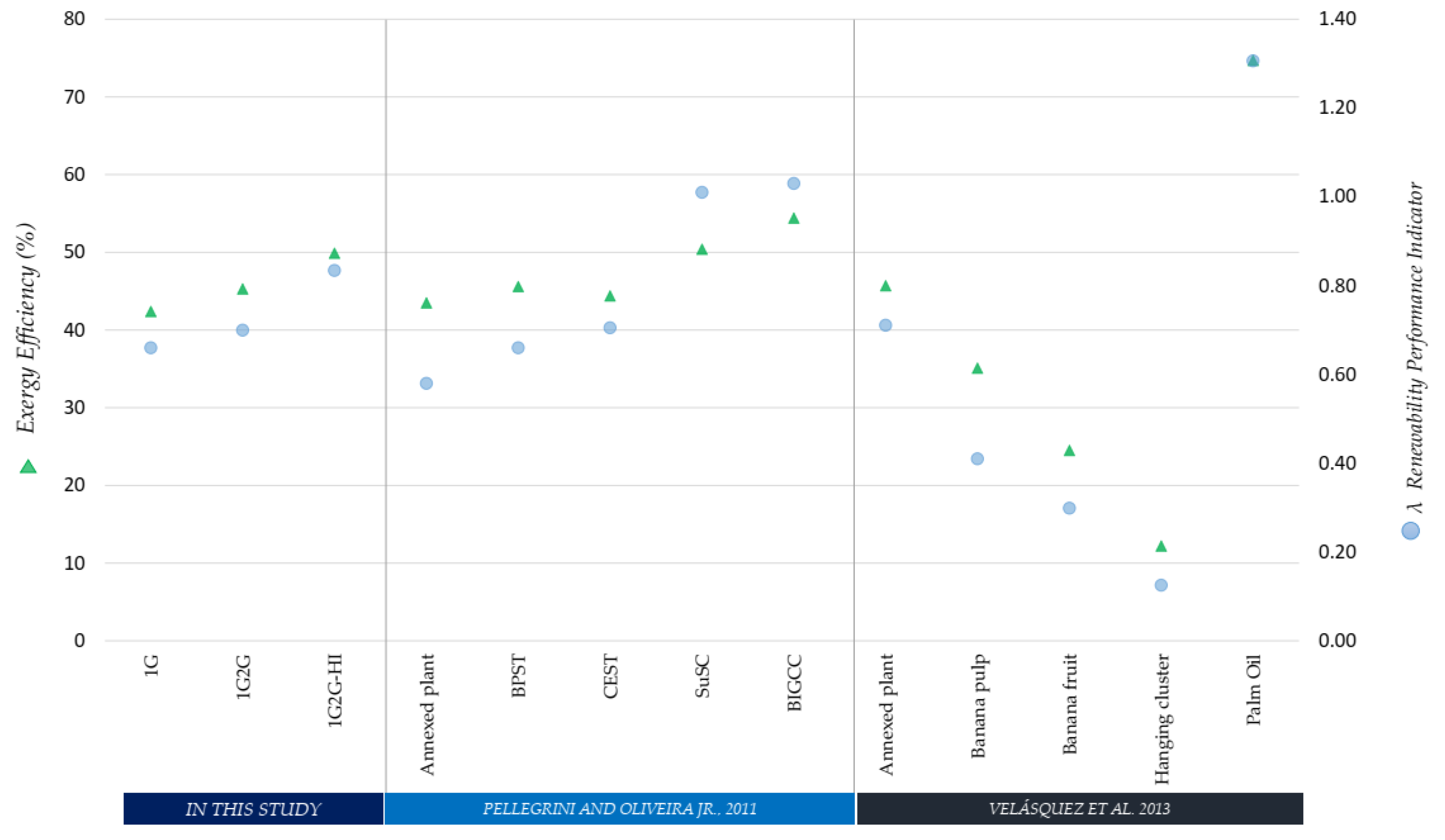
Figure 4 provides the λ results for the sugarcane plants. It is noted the relation between the exergy efficiency (ηB) and the associated exergy destruction (resource degradation) with regard to the renewability exergy index for several technological configurations. Although there is a direct relation, the terms involved in λindex allow a better analysis from the thermodynamic perspective of the alternatives to improve the renewability a given biofuel production (ethanol process), aiming to highlight their potential processing and consequent valorization.
First, the λ index was calculated considering the useful exergetic effects of the products Bproduct (ethanol and electricity) and later taking into account the exergy flow rate of byproducts. In light of these results, special attention must be given to these exergy values (Appendix A Section) in regards to the sugarcane-based biorefinery byproducts (i.e., filter cake, lignin cake, vinasse, and pentoses liquor) valorization.
λ renewability performance is ranked as environmentally unfavorable for the conventional, mass, and mass–heat integration cases analyzed in this study. The trend of λ index was to increase according to the levels of integration. In order to contrast the λ renewability performance of bioenergy systems and verify the relation between λ and the exergy efficiency, a comparison with respect to technological configurations is given in Figure 4.
For example, Pellegrini and Oliveira Jr. [41] presented a thermo-economic, environmental analysis, and optimization in sugarcane mills combining the production of sugar, ethanol, and electricity (as an annexed plant), evaluating different types of cogeneration systems. The results show λ = 0.66 and ηB = 43.5% in the exergy-based analysis of the traditional Brazilian mill (1G plant, base case). It has also been reported that the performance of the mentioned system could be improved by allowing commercialization of the surplus electricity. In this way, the λ indicator could be increased from 0.66 to 1.03, becoming the process renewable through the implementation of the biomass integrated gasification combined cycle (BIGCC) and supercritical cycle (SuSC) technologies. Furthermore, backpressure steam turbine (BPST) and condensing extraction steam turbine (CEST) systems have a λ lower than 1, indicating that these cogeneration processes may not be considered renewable from the second law of thermodynamics point of view [41].
Velásquez et al. [42] reported the exergo-environmental evaluation of liquid biofuel production. These authors indicated that the ethanol process from the lignocellulosic material contained in the hanging cluster of the banana plant represented the lowest performance, ηB (12.2%) and λindex (0.13). Thus, according to their λ values, the ethanol production from the amylaceous material contained in the banana pulp (λ = 0.41) and in the banana fruit (λ = 0.30) were determined as nonrenewable processes. Similarly, the traditional mill with λ (0.72) and ηB (45.7%) is also ranked in the same category (Figure 4). However, the exergy destroyed in the sugarcane 1G plant is slightly higher than the exergy in products (I/Bp = 1.06). Lastly, biodiesel production from the fresh fruit bunches (FFB) of palm oil exhibits the highest values of the nonrenewable exergy used in the production plant, mainly due to the high consumption of methanol (oil transesterification reaction). Thus, the use, in this case, of oils with a low free fatty acid content allows using less methanol in the reaction and obtained higher yields in the transesterification reaction, which results in a λ higher than 1.
A comparison related to fossil-based configurations reported by Carranza and Oliveira [43] shows the λ index calculation of an offshore platform for two case studies. First, an offshore plant without CO2 capture system (CCS) and next an offshore plant with CCS, getting λ values of 0.064 and 0.065, respectively. Thus, λ index of less than 1 indicate that these exploration processes of the oil and gas industry are environmentally unfavorable. According to the authors, these results are explained because the additional exergy consumption required by the CCS configuration is a nonrenewable resource, and its negative effect in λ index is more significant than the positive effect produced by the exergy of byproducts and the irreversibility of the emissions. Lastly, the insights when comparing 1G, 1G2G, and 1G2G-HI against the offshore plants show superior renewability of the processes that use renewable materials rather than fossil-based resources. Concerning the performance of autonomous plant (1G case) versus the annexed plants, it is noted the higher renewability of the latter due to the lower irreversibility of the processes involved in the joint sugar and ethanol production.
4.3. Analysis of KPIs for Ethanol Production Configurations
The overall performance of the ethanol production processes is carried out based on the KPIs applied to analyze the design and assessment of sugarcane biorefineries that combines usage of first- and second-generation (1G2G) feedstocks. Hence, the combination of process efficiency, exergy-based CO2-eq. emissions, and renewability indexes can give a better representation of a specified biorefinery system. Table 3 shows the main results obtained in the assessment of these technological scenarios in order to synthesize the performance criteria.
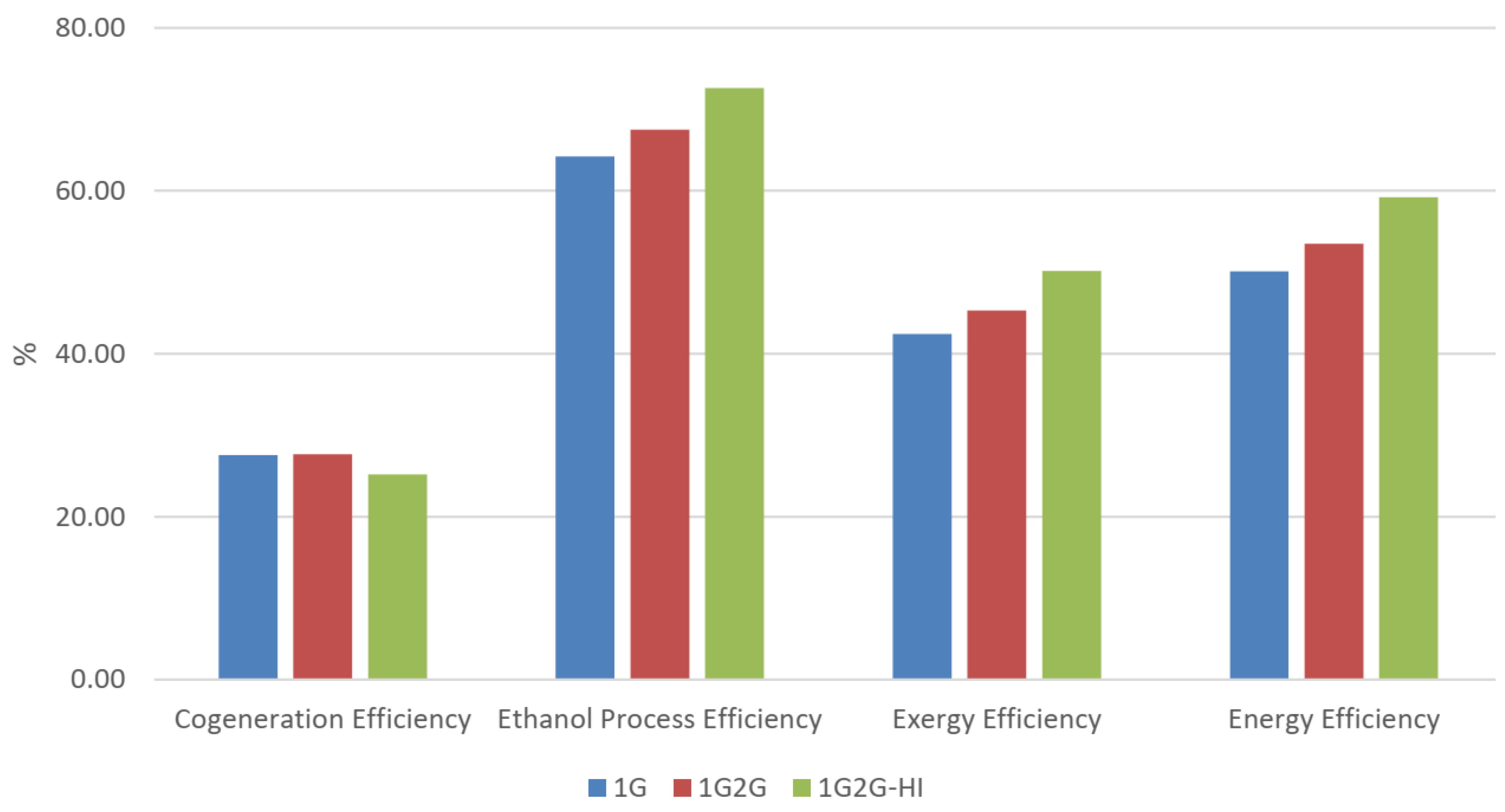
In general, the results of process performance show higher energy and exergy efficiencies for the 1G2G and 1G2G-HI plants, whereas the AUECprocess presents a reduction as a consequence of the irreversibility minimization at the different levels of integration. These values were compared with the exergetic assessment of the cogeneration process and the ethanol unit in Appendix A Section. Emphasizing that the efficiency of the utility system is lower (24%) for all the scenarios (Figure A5) once it entails a large amount of irreversibility in the combustion processes.
On the other hand, the exergy-based GHG emissions and renewability performance focuses on the cane ethanol process chain, which presented lower specific CO2 emissions for the mass and heat integration cases, allowing for a reduction in the carbon footprint related to the conventional process by 12% and 16%, respectively.
Even though the exergy values of the products (anhydrous ethanol and electricity) are considered in the λ calculation, the resulting renewability values of the sugarcane-based ethanol production processes are in all cases environmentally unfavorable (λ < 1). However, when the exergy flow of the byproducts is pondered, the λ increases as well to the point that 1G2G-HI represented a λ value higher than one (environmentally favorable). Regarding the steam demand of the configurations, base case (1G) achieved 739 kgsteam/t cane, mass integration (1G2G) attained 1048 kgsteam/t cane and mass–heat integration (1G2G-HI) reported 926 kgsteam/t cane. It represents a reduction of the steam consumption of 12% in contrast to the 1G2G case.
Benchmark with Other Sugarcane Biorefinery Studies
Findings of this study were compared with the literature. Table 4 shows the performance assessment of different technological configurations using the exergy values (Appendix A Section) and applying the exergy balance (Equation (4), Section 3.3). This table describes these configurations in order to contrast the findings with similar processes. Thus, global exergy efficiency, irreversibility rate, and the average unitary exergy cost (AUEC) were calculated for each sugarcane biorefinery, aiming to complement the analysis.
Dias et al. [11] show an ethanol production scale of 120 l/t cane for an integrated process (their Scenarios C and E), using steam explosion as pretreatment technology, which represents an increase of 46.9% in ethanol production and around 128% in power generation over their base case (1G plant).
Albarelli et al. [9] reported an integrated 1G and 2G process with thermal and water integration. With that, better use of energy and water was accomplished, allowing higher surplus electricity production. Palacios et al. [10] evaluated the exergy and exergetic cost associated with the ethanol production process from sugarcane biomass, including the route of bagasse enzymatic hydrolysis. The results showed that the exergy destruction resulting from the introduction of the enzymatic hydrolysis correspond to an important portion between 7–10% of the total exergy destruction and losses of the entire process.
5. Conclusions
Combined 1G2G-HI ethanol production plant resulted in a better thermodynamic performance in terms of destroyed exergy reduction compared to the base case (1G) and the mass integration (1G2G) configurations. This higher thermodynamic efficiency was basically due to the heat integration system, included as part of the conversion process, which allowed the lowest unitary exergy cost of these biorefineries. Thus, the pinch analysis led to an 8% reduction in the irreversibility, and a decrease of 12% steam consumption in contrast to the 1G2G case.
Furthermore, a technological comparison of the biorefinery scenarios (i.e., 1G, 1G2G and 2G) was carried out based on key performances indicators. Results showed the correlation between the exergy and renewability of the processes, which allowed to identify the use of renewable and nonrenewable resources associated with a particular system.
The exergy-based performance assessment can support decision-making for process design of a sugarcane ethanol plant towards a sustainable biorefinery configuration. Hence, the renewability index points out the effect of useful exergy of the products and byproducts involved in the cane-ethanol process chain once the byproducts’ valorization could translate in environmentally favorable systems. Lastly, it was demonstrated that the reduction of the entropy generation (destroyed exergy) in 1G2G-HI case mainly corresponds to increased efficiency in cogeneration and fermentation processes.
Author Contributions
Conceptualization and methodology design: P.A.S.O. and J.P.; data analysis and validation: P.A.S.O., R.M.F. and J.P.; writing—original draft preparation: P.A.S.O. and J.P.; supervision: R.M.F. and J.P.; project administration, R.M.F. and J.P.
Funding
This research was funded by the São Paulo Research Foundation (FAPESP), grants number 2017/03091-8 and 2017/16106-3.
Acknowledgments
The authors acknowledge the financial support of FAPESP. In addition, this work was carried out within the framework of the BIOEN thematic project, FAPESP process 2015/20630-4.
Conflicts of Interest
The authors declare no conflict of interest.
Nomenclature
| AUEC | Average unitary exergy cost (kJ/KJ). |
| B | Exergy flow rate (kW). |
| b | Specific exergy (kJ/kg). |
| BCO2EE | Specific carbon dioxide CO2 equivalent emissions (gCO2/MJ products). |
| Bch, i | Standard chemical exergy (MJ/kg, kJ/kmol). |
| Bdestroyed | Destroyed exergy (kW). |
| Bdeactivation | Destroyed exergy rate of additional natural resources during waste de-activation (kW). |
| Bdisposal | Exergy rate or flow rate related to waste disposal of the process (kW). |
| Bemissions | Exergy rate of wastes that are not treated or deactivated (kW). |
| Bfossil | Nonrenewable exergy rate consumed in production processes chain (kW). |
| Bproduct | Exergy rate or flow rate associated to the products and byproducts/useful effect (kW). |
| Butilities | Exergy rate or flow rate required by the utilities of the process (kW). |
| BQo | Supply heat exergy to the heat recovery section of the utility systems |
| c | Unit exergy cost |
| CO2-eq. | Carbon dioxide equivalent. |
| H, h | Enthalpy (kJ/kg) |
| I | Irreversibility rate (kW). |
| m | Mass flow rate (kg/s). |
| ƞB | Exergy Efficiency (%). |
| ƞE | Energy Efficiency (%). |
| R | Universal gas constant (J/mol K). |
| S, s | Entropy (KJ/kg-K) |
| T0 | Temperature (K). |
| xi | Mole fraction of component i. |
| v/v | Volume/Volume%. |
| w/w% | Weight Percent. |
| W | Power (kW). |
| Ὑ | Activity coefficient. |
| λ | Renewability exergy index. |
| φ | Ratio between the specific chemical exergy and the lower heating value. |
Abbreviations
| 1G | First-generation ethanol production process. |
| 2G | Second-generation ethanol production process. |
| 1G2G | Integrated first- and second-generation ethanol production technology. |
| BIGCC | Biomass integrated gasification combined cycle. |
| BPST | Backpressure steam turbine. |
| CEST | Condensing-extraction steam turbine. |
| CHP | Cogeneration system. |
| FPU | Filter paper cellulase units. |
| GWP | Global warming potential. |
| GHG | Greenhouse gases. |
| HEN | Heat exchanger network. |
| NRTL | Non-random two-liquid. |
| MEE | Multiple effect evaporation |
| LCA | Life cycle analysis and assessment. |
| LCI | Life cycle inventories. |
| LHV | Lower heating value. |
| KPIs | Key performance indicators. |
| SuSC | Supercritical cycles |
Appendix A
Appendix A.1. Feedstock Composition and Processing Capacity Adopted in the Simulations
Table A1 presents the feedstock composition (mass percent) adopted in this study for the sugarcane (SC), whereas Table A2 shows the dry mass composition of SC bagasse and straw used as inputs. Lastly, Table A3 displays the processing capacity adopted in the simulations.

Table A1.
Raw material composition.
| Formula | Components 1 | Molar Weights (g/mol) | Sugarcane Composition (w/w%) |
|---|---|---|---|
| C6H10O5 | Cellulose | 162.14 | 5.95 |
| C5H8O4 | Hemicellulose | 132.12 | 3.52 |
| C7.3H13.9O1.3 | Lignin | 122.49 | 3.19 |
| C12H22O11 | Sucrose | 342.29 | 13.92 |
| C6H12O6 | Glucose | 180.16 | 0.60 |
| K2O | Minerals | 94.2 | 0.20 |
| KCl | Potassium chloride (salts) | 74.55 | 1.17 |
| C6H6O6 | Aconitic acid (organic acids) | 174.1 | 0.6 |
| H2O | Water | 18.015 | 69.82 |
| SiO2 | Silicon dioxide (soil) | 60.08 | 1.03 |
Table A2.
Dry mass composition of sugarcane (SC) bagasse and straw.
| Components 1 | Bagasse | Straw |
|---|---|---|
| Carbon | 0.50 | 0.47 |
| Hydrogen | 0.07 | 0.07 |
| Oxygen | 0.41 | 0.38 |
| Ash | 0.02 | 0.08 |
1 Palacios-Bereche [44].
Table A3.
Processing capacity adopted in the simulations.
| Process Parameters | Value | Units | References |
|---|---|---|---|
| Sugarcane processed (wet basis) | 4 | million t cane/year | [19] |
| Harvest period (operation time) | 200 | days | [19] |
| Straw production (dry basis) | 140 | kg/t cane | [45] |
| Straw fraction recovered from the field | 50 | % | [45] |
| Sugar extraction efficiency | 96 | % | [19] |
| Straw moisture | 30 | % | [19] |
| Bagasse moisture | 50 | % | [19] |
Appendix A.2. Technical Parameters of the First-Generation Ethanol Plant
The technical parameters for a standard sugarcane biorefinery are presented in Table A4. Hence, the assumptions in the simulation of the first-generation (1G) ethanol process are specified in this table for each subsystem under consideration.
Table A4.
Main technical parameters used in the traditional ethanol production (1G) plant simulation.
Table A4.
Main technical parameters used in the traditional ethanol production (1G) plant simulation.
| Process Parameters | Value | Units | References |
|---|---|---|---|
| JUICE TREATMENT | |||
| First juice stage—temperature heating | 70 | °C | [23] |
| Phosphate content of the juice after H3PO4 addition | 250 | ppm | [25] |
| Amount of lime added in liming (ethanol/sugar production) | 0.6/1.0 | kgCaO/t cane | [25] |
| Second juice stage—temperature heating | 105 | °C | [19] |
| Filter cake moisture content | 60–70 | % | [25] |
| Insoluble solid retention in the filter | 65 | % | [25] |
| Wash water related to filter cake | 15 | % | [23] |
| Bagasse fines supplemented in the filter | 6 | kg/t cane | [23] |
| Removal efficiency of insoluble solids in the clarified juice | 65 | % | [25] |
| JUICE CONCENTRATION | |||
| Effects number in the evaporation process | 5 | - | [25] |
| Syrup | 65 | ° Brix | [25] |
| FERMENTATION AND CELL TREATMENT | |||
| Fraction of the reactor fed with yeast solution | 25 | w/w% | [23] |
| Fermentation temperature | 33 | °C | [23] |
| Efficiency of solid retention (centrifuges) | 99 | % | [25] |
| Ethanol content in the wine (distillation feed) | 80 | g/L | [25] |
| Ethanol content of the yeast concentrated solution (centrifuges) | 6.5 | w/w% | [25] |
| H2SO4 addition in yeast treatment (on 100% basis) | 5 | kg/m3 ethanol | [25] |
| DISTILLATION | |||
| Vinasse and phlegmasse ethanol content | <200 | ppm | [19] |
| Fusel oil per ethanol produced | 0.2 | v/v% | [19] |
| Hydrated ethanol purity | 93 | w/w% | [19] |
| MOLECULAR SIEVES | |||
| Feed temperature | 150 | °C | [23] |
| Steam pressure | 6 | bar | [23] |
| Ethanol recovered as final product | 81.4 | % | [25] |
| Anhydrous ethanol (AE) purity | 99.6 | w/w% | [45] |
| Molecular sieves steam consumption | 0.6 | kgsteam/lAE | [45] |
In the simulation of the fermentation process (C6 sugars) were taken into account the following reactions (Table A5).
Table A5.
Fermentation Reactions.
| FERMENTATION REACTIONS 1 | Description | Equation |
|---|---|---|
| C12H22O11 + H2O → 2C6H12O6 | Sucrose inversion | (A1) |
| C6H12O6 → 2C2H6O + 2CO2 | Ethanol production | (A2) |
| 3.2618 C6H12O6 + 2.8469 NH4OH +2.1352 CO2 → 1.0359 C2H4O2 + 6.9454 H2O + 19.6342 CH1.8O0.9N0.1 | Cell growth | (A3) |
| 0.7630 C6H12O6 → 0.7630 C4H10O + 1.5260 CO2 + 0.7630 H2O | By-products Formation | (A4) |
| 0.6107 C6H12O6 + 0.5236 H2O → 0.5234 CO2 + 1.047 C3H8O3 | (A5) | |
| C6H12O6 → 3C2H4O2 | (A6) | |
| 0.827 C6H12O6 → 0.662 C5H12O + 1.654 CO2 + 0.9927 H2O | (A7) |
1 Bonomi et al. 2016 [17].
In the model, it was assumed that these reactions occur sequentially. The reactions comprise sucrose hydrolysis (A1), ethanol production (A2), yeast growth (A3), and formation of byproducts (isoamyl alcohol (A4), isobutanol (A5), glycerol (A6) and acetic acid (A7)).
In addition, A1 conversion was fixed as 100%, whereas A2 was defined in 90% (average yields of a conventional fermentation process). Reactions from A3 to A7 had their stoichiometric coefficients estimated in order to balance the equations as indicated in Bonomi et al. 2016 [17].
Appendix A.3. Process Flow Diagrams
The flowsheet of the ethanol production process implemented in Aspen Plus is given in Figure A1, where Col. A, Col. A1, Col. B-B1, and Col. D represented the stripping section, rectification section, phlegm rectification, and the top concentrator in the distillation unit, respectively. Furthermore, the process flow diagram of the second-generation production is described in Figure A2 and the flowsheet diagram of Figure A3 shows the utility system (cogeneration unit).
Figure A1.
Flow diagram of the ethanol production process.

Figure A2.
Process flow diagram of the second-generation ethanol production.

Figure A3.
Process flow diagram of the utility system.

Appendix A.4. Technical Parameters of the Cogeneration System
The cogeneration system (CHP unit) adopted in the simulation consists of a steam cycle with backpressure steam turbines. The main process parameters and chemical reactions involved in the cogeneration section are given in Table A6.
Table A6.
Combined heat and power unit.
| Process Parameters | Value | Units | References |
|---|---|---|---|
| COGENERATION SYSTEM | |||
| Steam temperature (superheated steam) | 485 | °C | [46] |
| Pressure of the boiler system | 65 | bar | [46] |
| Boiler thermal efficiency (LHV basis) | 87.7 | % | [46] |
| Gases outlet temperature | 160 | °C | [46] |
| Turbine isentropic efficiency | 85 | % | [46] |
| Generator efficiency | 98 | % | [46] |
| Isentropic efficiency of direct drive steam turbines | 50 | % | [24] |
| Pump isentropic efficiency | 70 | % | [24] |
| Electricity consumption 1G | 30 | kWh/t cane | [47] |
| Condensing pressure | 0.11 | bar | [47] |
| Condensate losses | 5 | % | [47] |
| Fraction of bagasse for start-ups of the plant | 5 | % | [47] |
| CHEMICAL REACTIONS (boiler section) | Equation | ||
| C6H10O5 + 6O2 → 5H2O + 6CO2 | (A8) | ||
| C5H8O4 + 5O2 → 4H2O + 5CO2 | (A9) | ||
| C7.3H13.9O1.3 + 10.95O2 → 5.8H2O + 10CO2 | (A10) | ||
In the boiler section, the combustion reactions for each component present in the lignocellulosic material (mainly cellulose, hemicellulose, and lignin) were inserted in the simulation as solid components (Table A12) and conversion was set as 100%. Thus, the inefficiencies of the boiler were represented as the loss of a fraction of the hot gases after combustion. Therefore, the lower heating value (LHV) of sugarcane bagasse (50% moisture) and straw SC (15% moisture) was calculated based on the enthalpy of combustion for each component as given in Table A13.
Appendix A.5. Technical Parameters of the Second-Generation Ethanol Process
The 2G process was based on the steam pretreatment technology followed by an advanced enzymatic hydrolysis process. Table A7 depicts the detailed parameter conditions implemented in the 1G2G ethanol simulation process.
Stoichiometric model reactors were utilized to denote pretreatment and hydrolysis reactors as well as pH adjustment and fermentation of C5 liquor. Solid–liquid separation units (diffuser and filter) and centrifuge were simulated taking into account the separation efficiencies.
Table A7.
Main technical parameters adopted in the simulation of the second-generation (2G) ethanol process.
Table A7.
Main technical parameters adopted in the simulation of the second-generation (2G) ethanol process.
| Process Parameters 1 | ||
|---|---|---|
| STEAM EXPLOSION PRETREATMENT | Value | Units |
| Temperature | 210 | °C |
| Residence time | 5 | min |
| Pretreatment reactor pressure | 12.5 | bar |
| Pretreatment reactor steam consumption | 0.55 | kgsteam/kgfeedstock |
| Pressure at unitary pretreatment block | 1.01 | bar |
| Cellulose solubilization | 5.5 | % |
| DIFFUSER | Value | Units |
| Proportion of water added | 180 | % of cellulignin fibers |
| Insoluble solid retention | 99.5 | % |
| Soluble solids recovered in the liquor | 98 | % |
| Cellulignin moisture | 50 | % |
| ENZYMATIC HYDROLYSIS | Value | Units |
| Temperature | 65 | °C |
| Residence time | 36 | h |
| Enzymatic load—cellulase | 53 | FPU/g dry biomass |
| Enzymatic load—bglucosidase (enzyme activity) | 83 | IU/g dry biomass |
| Solid content | 20 | % |
| Cellulose conversion to glucose | 80 | % |
| Xylan conversion to xylose | 80 | % |
| Electricity consumption for the 2G process | 51 | kWh/t cane |
| PRETREATMENT REACTIONS | Yield (%) | Equation |
| C5H8O4 + H2O → C5H10O5 | 61.4 | (A11) |
| C5H8O4 + H2O → 2.5C2H4O2 | 9.2 | (A12) |
| C5H10O5 → C5H4O2 + H2O | 5.1 | (A13) |
| C6H10O5 + H2O → C6H12O6 | 4.1 | (A14) |
| HYDROLYSIS REACTIONS | Yield (%) | Equation |
| C5H8O4 + H2O → C5H10O5 | 40.6 | (A15) |
| C6H10O5 + H2O → C6H12O6 | 55.8 | (A16) |
Simultaneously to pentose fermentation, deoligomerization reactions (Equations (A17) and (A18)) occur in the reactor. Additionally, glucose conversion, ethanol production (Equation (A19)) and byproduct formation (Equations (A20)–(A23)) from xylose were inserted in the simulation, as given in Table A8. Hence, the reaction conversion of Equations (A17)–(A19) was fixed as 80%, whereas reactions from Equations (A20)–(A23) had their stoichiometric coefficients estimated in order to balance the equations as indicated in Bonomi et al. 2016 [17].
Table A8.
Pentose fermentation reactions.
| PENTOSE FERMENTATION 1 | Description | Equation |
|---|---|---|
| C5H10O5 Oligomers + n H2O → n C5H10O5 | Deoligomerization reactions | (A17) |
| C6H12O6 Oligomers + n H2O → n C6H12O6 | (A18) | |
| 3C5H10O5 → 5C2H6O + 5CO2 | Ethanol production | (A19) |
| 6C5H10O5 → 5C4H10O + 10CO2 + 5H2O | Formation of by-products | (A20) |
| 7C5H10O5 + 5H2O → CO2 + 10C3H8O3 | (A21) | |
| 2C5H10O5 → 5C2H4O2 | (A22) | |
| 3C5H10O5 → C5H12O + 5CO2 + 3H2O | (A23) |
1 Bonomi et al. 2016 [17].
Appendix A.6. Data Extraction
The thermodynamic parameters of hot streams or process heat sources, which present a cooling demand (heat supply), and cold streams or process heat sinks, which present a heat demand for heat integration through pinch analysis were described in the Table A9.
Table A9.
Streams selected for heat integration.
| Hot Streams | Tinitial Ti (°C) | Tfinal Tf (°C) | Heat Flow ∆H (MW) | Heat Flow 1 (MJ/t) |
| H1 Sterilization of juice | 130.0 | 32.0 | 55.3 | 5501 |
| H2 Fermented wine | 39.0 | 33.0 | 10.2 | 1015 |
| H3 Vinasse | 109.3 | 35.0 | 37.5 | 3730 |
| H4 Anhydrous ethanol | 81.5 | 35.0 | 12.4 | 1231 |
| H5 Vapor Condensates | 85.2 | 35.0 | 15.0 | 1487 |
| H6 Condenser column B (Concentration) | 81.6 | 81.6 | 26.5 | 2636 |
| H7 Condenser column D (Rectification) | 85.1 | 32.0 | 32.5 | 3233 |
| H8 Vapor recovered from steam explosion | 100.9 | 100.0 | 16.6 | 1651 |
| Cold Streams | Tinitial Ti (°C) | Tfinal Tf (°C) | Heat Flow ∆H (MW) | Heat Flow 1 (MJ/t) |
| C1 Juice treatment | 34.2 | 98.0 | 42.7 | 4247 |
| C2 Juice preheating (before MEE) | 98.0 | 120.0 | 10.8 | 1074 |
| C3 Juice for sterilization | 89.0 | 130.0 | 21.4 | 2129 |
| C4 Centrifuged wine | 31.2 | 89.0 | 39.4 | 3919 |
| C5 Reboiler column A | 112.1 | 112.1 | 59.5 | 5922 |
| C6 Reboiler column B (Rectification) | 104.0 | 104.0 | 37.2 | 3699 |
| C7 Reboiler recovery column | 149.6 | 149.6 | 2.6 | 259 |
| C8 Hydrolysis water | 30.0 | 50.0 | 8.6 | 855 |
| C9 Glucose liquor preheating | 50.0 | 115.0 | 29.6 | 2944 |
1 Energy requirement per ton of ethanol.
Appendix A.7. Unit Exergy Cost and Exergy Efficiency
Figure A4 showed the unit exergy cost c (kJ/kJ) of the anhydrous ethanol and the electricity calculated in this study as the exergy efficiency inverse of the ethanol process and cogeneration unit, respectively. In addition, Figure A5 presented the exergy assessment of the cogeneration process, the ethanol unit, and the overall configuration. Later, the exergy efficiency definitions for each system are given in Table A10.
Figure A4.
Average unitary exergy cost (AUEC) of each configuration.

Figure A5.
Efficiency comparison for each configuration.

Table A10.
Unit exergy cost and exergy efficiency definitions.
| Definition | Equation | |
|---|---|---|
| Unit exergy cost, c | (A24) | |
| Cogeneration unit | (A25) | |
| Ethanol process 1 | (A26) | |
| Overall process | (A27) |
1 The term Bresources represents the exergy of the raw material, whereas Bfossil denotes the exergy associated with the chemical and biochemical compounds specified in Table A14.
Appendix A.8. Life Cycle Inventory
Table A11 shows the life cycle inventory for the conversion processes per ton of processed sugarcane.
Table A11.
Life cycle inventory data 1.
| Compounds | GHG (kgCO2/x) | Units | Comments |
|---|---|---|---|
| Sugarcane (SC) | 0.034 | kg SC | Including transportation, without trash burning, with sugar yield of our process |
| SC straw | 0.01 | kg SC straw | Using the yield of sugars, of SC straw/SC |
| H3PO4 | 1.423 | kg H3PO4 | Commercial phosphoric acid used has a concentration of 85% by mass |
| CaO | 0.15 | kg CaO | Lime |
| H2SO4 | 0.124 | kg H2SO4 | Sulfuric acid |
| NH4OH | 2.089 | kg NH4OH | Ammonia, liquid at regional storehouse/kg/RER 2 |
| Enzyme | 4.09 | kg Enzyme | Enzyme cocktail |
| NaOH | 1.096 | kg NaOH | Analyzing 1 kg ‘Sodium hydroxide, 50% in H2O, production mix at plant/RER 3’ |
| SO2 | 0.44 | kg SO2 | Sulphur dioxide, liquid, SO2 |
| C2H4O2 | 1.403 | kg C2H4O2 | Acetic acid via methanol carbonylation |
| Electricity | 0.486 | kwh | Electricity, Brazilian mix GLO/kWh |
Appendix A.9. Standard Chemical Exergy
Table A12 shows the standard chemical exergy (bch) for the conventional compounds used in the exergy analysis. Furthermore, Equation (A28) presents a correlation related to the bch calculations of the ‘nonconventional’ components that were inserted, such as solids in the models carried out in Aspen Plus.
Table A12.
Standard chemical exergy of the compounds used in the simulations.
| Chemical Formula | Component | Type | bCH Specific (kJ/kmol) |
|---|---|---|---|
| C6H10O5 | Cellulose ** | Solid | 3,404,400 |
| C5H8O4 | Hemicellulose ** | Solid | 2,826,640 |
| C7.3H13.9O1.3 | Lignin ** | Solid | 3,449,500 |
| Ca3(PO4)2 | Calcium phosphate ** | Solid | 19,400 |
| CH1.8O0.9N0.1 | Yeast1 ** | Solid | 513,560 |
| CH1.57N0.29O0.31S0.007 | Enzyme 2 ** | Solid | 541,376 |
| CaO | Calcium oxide * | Conventional | 110,200 |
| Ca(OH)2 | Calcium hydroxide * | Conventional | 53,700 |
| CO | Carbon monoxide * | Conventional | 275,100 |
| CO2 | Carbon dioxide * | Conventional | 19,870 |
| C2H6O | Anhydrous ethanol * | Conventional | 1,250,900 |
| C6H12O6 | Dextrose (Glucose) * | Conventional | 2,928,800 |
| C2H4O2 | Acetic acid * | Conventional | 908,000 |
| C3H8O3 | Glycerol * | Conventional | 1,705,600 |
| C5H10O5 | Xylose ** | Conventional | 2,361,900 |
| C5H4O2 | Furfural * | Conventional | 2,338,700 |
| C5H12O | Isoamyl alcohol * | Conventional | 3,311,700 |
| C4H6O | Succinic acid * | Conventional | 1,609,400 |
| C6H6O6 | Organic acids * (Aconitic acid) | Conventional | 3,128,500 |
| C12H22O11 | Sucrose * | Conventional | 6,007,800 |
| K2O | Potassium oxide * | Conventional | 413,100 |
| KCl | Potassium chloride * (Salts) | Conventional | 19,600 |
| NO | Nitric oxide * | Conventional | 88,900 |
| N2 | Nitrogen * | Conventional | 720 |
| O2 | Oxygen * | Conventional | 3970 |
| H2 | Hydrogen * | Conventional | 236,100 |
| H2O | Water * | Conventional | 900 |
| H2SO4 | Sulphuric acid * | Conventional | 163,400 |
| H3PO4 | Phosphoric acid * | Conventional | 104,000 |
| NH3 | Ammonia * | Conventional | 337,900 |
| NH4OH | Ammonium hydroxide 3 | Conventional | 328,800 |
| SiO2 | Silicon dioxide 4 | Solid | 3545 |
| SO2 | Sulfur dioxide * | Conventional | 313,400 |
* Adopted values for bCHspec from Szargut et al. [31]. ** Calculated using the correlations linking the ratio of the standard chemical exergy and the net calorific value of the substances [34]. 1 For the enzymes, the composition (CH1.57N0.29O0.31S0.007) was assumed, as indicated per NREL [21]. 2 The yeast component was created based on the chemical formula (CH1.8O0.9N0.145) specified by Eijsberg [48]. 3 Adopted values from Szargut 2005 [49]. 4 A content of amorphous material of 25% was considered in the calculation of the bCH specific of SiO2. In addition, the proportions of cristobalite and quartz were assumed to have 16% and 59% (in mass), according to the parameters for sugarcane bagasse ash reported in Cordeiro et al. [50].
The following expression was used in terms of mass ratios for dry organic materials contained in solid fossil fuels consisting of c, h, o, and n with a mass ratio of oxygen to carbon less than 0.667; where c, h, o, and n are the mass fractions of carbon, hydrogen, oxygen, and nitrogen, respectively. According to Kotas [34], the accuracy of this expression is estimated to be better than ±1%.
Calculation of standard chemical exergy of the ‘nonconventional’ compounds.
Appendix A.10. Standard Chemical Exergy and Lower Heating Value for Selected Resources
It is noted that the specific chemical exergy in reference conditions of temperature and pressure (T0 and P0) are usually close, or equal to, its heating value (LHV). Table A13 presents the bch and LHV values for several fossils and bio-based raw materials.
Table A13.
Values of bch and LHV for diverse compounds.
| Standard Chemical Exergy | Net Calorific Value | ||||
|---|---|---|---|---|---|
| FORMULA | SUBSTANCES | bCH (MJ/kg) | References | LHV (MJ/kg) | References |
| FOSSIL RAW MATERIALS | |||||
| H2 | Hydrogen (g) | 117.12 | [31] | 120.00 | [51] |
| CH4 | Methane, Natural Gas (g) | 51.84 | [31] | 45.00 | [51] |
| Crude Oil | 42.38 | [52] | 42.69 | [53] | |
| Coal (s) | 23.59 | [52] | 22.73 | [53] | |
| CnH1.87n | Gasoline (l) | 47.39 | [54] | 44.00 | [51] |
| BIOMASS/BIOBASED FEEDSTOCK | |||||
| C6H12O6 | Glucose-D-Galactose (Cellulose) | 16.26 | [31] | 15.60 | [55] |
| Sugarcane bagasse 1 | 9.67 | 17.55 | |||
| Sugarcane 1 | 5.22 | 4.43 | |||
| Straw 1 | 13.84 | 11.5 | |||
| Plant Oil | 40.00 | [35] | 35.60 | [53] | |
| INTERMEDIATES | |||||
| C2H4 | Ethene (Ethylene) (g) | 48.52 | [31] | 47.16 | [56] |
| C2H6O | Anhydrous ethanol (l) | 29.47 | [31] | 26.81 | [51] |
| CH4O | Methanol (l) | 22.41 | [31] | 20.09 | [51] |
| C3H8O3 | Glycerol | 18.52 | [57] | 14.30 | [58] |
| CO | Carbon monoxide | 9.82 | [31] | 10.10 | [51] |
| CO2 | Carbon dioxide | 0.45 | [31] | 0 | - |
| PRODUCTS | |||||
| (C2H4)n | PE—Polyethylene | 46.0 | [35] | 40.0 | [59] |
| (C3H6)n | PP—Polypropylene | 45.5 | [35] | 41.0 | [59] |
| (C2H3Cl)n | PVC—Polyvinyl chloride | 45.0 | [35] | 42.9 | [59] |
| (C8H8)n | PS—Polystyrene | 38.0 | [35] | 38.6 | [59] |
| (C10H8O4)n | PET—Polyethylene terephthalate | 24.7 | [35] | 23.8 | [59] |
| Sugar | 17.5 | [41] | - | ||
(s): Solid, (l): liquid, (g): gas. 1 Calculated based on the correlation for the standard chemical exergy of the ‘nonconventional’ compounds, as described in the previous section.
Appendix A.11. Renewability Exergy Index Calculation
The λindex components used in the assessment of the industrial processing stage are presented in Table A14. The λindex calculation was addressed according to Equation (9) through the exergy of the ‘fossil’ (chemical and biochemical inputs), the exergy of products, the exergy of the CO2 emissions, and the irreversibilities. It is worth mentioning that the exergy flow rates (kW) are given in terms of the processing capacity of each biorefinery plant.
Table A14.
Estimated exergy terms involved in renewability exergy calculation.
| 1G | 1G2G | 1G2G-HI | |
|---|---|---|---|
| B Fossil | kW | kW | kW |
| Sulfuric acid (H2SO4) | 47,031 | 38,674 | 38,674 |
| Nutrients (NH4OH) | 1442 | 4441 | 4441 |
| Phosphoric acid (H3PO4) | 41.34 | 33.55 | 33.55 |
| Calcium oxide (CaO) | 278.91 | 293.7 | 293.7 |
| Enzymes | - | 51,581 | 51,581 |
| Yeast | 6260 | 12,521 | 12,521 |
| ∑ Bfossil inputs (kW) | 55,053 | 107,544 | 107,544 |
| B products | |||
| Surplus electricity | 140,320 | 41,542 | 43,567 |
| Anhydrous ethanol | 446,328 | 584,795 | 646,520 |
| ∑ Bproducts (kW) | 586,648 | 626,336 | 690,087 |
| B by-products1 | |||
| Filter cake | 12,572 | 7552 | 7552 |
| Lignin cake | 0 | 70,213 | 70,680 |
| Vinasse | 72,866 | 91,099 | 99,004 |
| Pentoses Liquor | 0 | 34,942 | 37,250 |
| ∑ Bby-products (kW) | 71,285 | 217,032 | 221,049 |
| B emissions | |||
| CO2 Emissions 1 | 42,536 | 30,580 | 29,326 |
| ∑ Bemissions (kW) | 42,536 | 30,580 | 29,326 |
| Irreversibilities | |||
| ∑ Bdestroyed (kW)2 | 795,713 | 756,025 | 692,274 |
| Bin (%)3 | 57.6 | 54.7 | 50.1 |
| kWh/lethanol4 | 14.6 | 8.3 | 8.8 |
1 The exergy flow rate (kW) of the component i is determined based on the mass flow rate (kg/s) and the standard chemical exergy (kJ/kg), . 2 Irreversibility per raw material, SC (833 t/h) and SC Straw (44.95 t/h). 3 Irreversibility per percentage of total exergy of the inputs. 4 Irreversibilities in terms of the ethanol production.
Appendix A.12. Properties of the Key Streams and Irreversibilities per Liter of Ethanol in the Systems
This Appendix A Section shows the parameters of the key streams of the biorefinery configurations. Thus, Table A15 presents the operating conditions of the flows involved in the 1G case. Furthermore, Table A16 and Table A17 indicate the key streams of the mass-integrated (1G2G) and mass and heat-integrated system (1G2G-HI), respectively. Lastly, Table A18 presents the irreversibilities per liter of ethanol of each system.
Table A15.
Key streams parameters of the traditional ethanol production (1G).
| MW | |||||
|---|---|---|---|---|---|
| Streams | m (kg/s) | T (°C) | P (bar) | b (kJ/kg) | B (MJ/s) |
| Cane | 231.48 | 25 | 1.013 | 5223 | 1209.03 |
| Bagasse | 62.81 | 25 | 1.013 | 9667 | 607.23 |
| Straw | 12.49 | 25 | 1.013 | 13,845 | 172.87 |
| Sulfuric acid (H2SO4) | 28.23 | 25 | 1.013 | 1666 | 47.03 |
| Nutrients (NH4OH) | 0.15 | 25 | 1.013 | 9382 | 1.44 |
| Phosphoric acid (H3PO4) | 0.04 | 25 | 1.013 | 1061 | 0.04 |
| Calcium Oxide (CaO) | 0.14 | 25 | 1.013 | 1965 | 0.28 |
| Yeast | 0.36 | 33 | 1.013 | 17,350 | 6.26 |
| Filter cake | 5.82 | 98 | 1.013 | 2162 | 12.57 |
| Vinasse | 164.48 | 75 | 1.4 | 443 | 72.87 |
| Anhydrous ethanol | 15.14 | 78 | 1.013 | 29,471 | 446.33 |
| CO2 Emissions | 94.19 | 25 | 1.013 | 451.59 | 42.54 |
Table A16.
Key streams parameters of the mass-integrated case (1G2G).
| MW | |||||
|---|---|---|---|---|---|
| Streams | m (kg/s) | T (°C) | P (bar) | b (kJ/kg) | B (MJ/s) |
| Cane | 231.48 | 25 | 1.013 | 5223 | 1209.03 |
| Bagasse | 62.81 | 25 | 1.013 | 9667 | 607.23 |
| Straw | 12.49 | 25 | 1.013 | 13,845 | 172.87 |
| Sulfuric acid (H2SO4) | 23.21 | 25 | 1.013 | 1666 | 38.67 |
| Nutrients (NH4OH) | 0.47 | 25 | 1.013 | 9382 | 4.44 |
| Phosphoric acid (H3PO4) | 0.03 | 25 | 1.013 | 1061 | 0.03 |
| Calcium Oxide (CaO) | 0.15 | 25 | 1.013 | 1965 | 0.29 |
| Enzymes | 2.17 | 30 | 1.013 | 23,730 | 51.58 |
| Yeast | 0.72 | 33 | 1.013 | 17,350 | 12.52 |
| Filter cake | 3.49 | 98 | 1.013 | 2162 | 7.55 |
| Lignin cake | 6.50 | 50 | 1.013 | 10,802 | 70.21 |
| Vinasse | 205.64 | 75 | 1.4 | 443 | 91.10 |
| Pentoses liquor | 20.57 | 37 | 1.013 | 1699 | 34.94 |
| Anhydrous ethanol | 19.84 | 78 | 1.013 | 29,471 | 584.79 |
| CO2 Emissions | 64.94 | 25 | 1.013 | 451.59 | 29.33 |
Table A17.
Key streams parameters of the mass and heat-integrated system (1G2G-HI).
| MW | |||||
|---|---|---|---|---|---|
| Streams | m (kg/s) | T (°C) | P (bar) | b (kJ/kg) | B (MJ/s) |
| Cane | 231.48 | 25 | 1.013 | 5223 | 1209.03 |
| Bagasse | 62.81 | 25 | 1.013 | 9667 | 607.23 |
| Straw | 12.49 | 25 | 1.013 | 13,845 | 172.87 |
| Sulfuric acid (H2SO4) | 23.21 | 25 | 1.013 | 1666 | 38.67 |
| Nutrients (NH4OH) | 0.47 | 25 | 1.013 | 9382 | 4.44 |
| Phosphoric acid (H3PO4) | 0.03 | 25 | 1.013 | 1061 | 0.03 |
| Calcium Oxide (CaO) | 0.15 | 25 | 1.013 | 1965 | 0.29 |
| Enzymes | 2.17 | 30 | 1.013 | 23,730 | 51.58 |
| Yeast | 0.72 | 33 | 1.013 | 17,350 | 12.52 |
| Filter cake | 3.49 | 98 | 1.013 | 2162 | 7.55 |
| Lignin cake | 6.54 | 50 | 1.013 | 10,802 | 70.68 |
| Vinasse | 223.49 | 75 | 1.4 | 443 | 99.00 |
| Pentoses liquor | 21.92 | 37 | 1.013 | 1699 | 37.25 |
| Anhydrous ethanol | 21.94 | 78 | 1.013 | 29,471 | 646.52 |
| CO2 Emissions | 64.94 | 25 | 1.013 | 451.59 | 29.33 |
Table A18.
Irreversibilities per liter of ethanol in the systems.
| kWh/Lethanol | |||
|---|---|---|---|
| Sub-System | 1G | 1G2G | 1G2G-HI |
| Preparation and Extraction | 1.192 | 0.742 | 0.629 |
| Juice Treatment | 0.554 | 0.350 | 0.297 |
| Juice Concentration | 0.213 | 0.125 | 0.098 |
| Fermentation | 1.760 | 1.001 | 0.835 |
| Distillation | 0.719 | 0.534 | 0.419 |
| Dehydration | 0.065 | 0.044 | 0.031 |
| Cogeneration | 6.719 | 4.841 | 3.989 |
| Condensate tank | 0.161 | 0.090 | 0.075 |
| 2G Unit | - | 0.527 | 0.465 |
| TOTAL | 11.38 | 8.25 | 6.84 |
References
- Joelsson, E.; Galbe, M.; Wallberg, O. Heat integration of combined 1st and 2nd generation ethanol production from wheat kernels and wheat straw. Sustain. Chem. Process. 2014, 2, 20. [Google Scholar] [CrossRef]
- RFA. Renewable Fuels Association—Leading trade association for US ethanol, Renewable Fuels Association. Available online: https://ethanolrfa.org/ (accessed on 29 October 2018).
- Dias, M.O.S.; Lima, D.R.; Mariano, A.P. Techno-Economic Analysis of Cogeneration of Heat and Electricity and Second-Generation Ethanol Production from Sugarcane. In Advances in Sugarcane Biorefinery; Chandel, A.K., Luciano Silveira, M.H., Eds.; Elsevier: Amsterdam, The Netherlands, 2018; pp. 197–212. [Google Scholar] [CrossRef]
- Cagno, E.; Neri, A.; Howard, M.; Brenna, G.; Trianni, A. Industrial sustainability performance measurement systems: A novel framework. J. Clean. Prod. 2019, 230, 1354–1375. [Google Scholar] [CrossRef]
- Magnanelli, E.; Berglihn, O.T.; Kjelstrup, S. Exergy-based performance indicators for industrial practice. Int. J. Energy Res. 2018, 42, 3989–4007. [Google Scholar] [CrossRef] [Green Version]
- Stougie, L.; Giustozzi, N.; van der Kooi, H.; Stoppato, A. Environmental, economic and exergetic sustainability assessment of power generation from fossil and renewable energy sources. Int. J. Energy Res. 2018, 42, 2916–2926. [Google Scholar] [CrossRef]
- Posada, J.A.; Brentner, L.B.; Ramirez, A.; Patel, M.K. Conceptual design of sustainable integrated microalgae biorefineries: Parametric analysis of energy use, greenhouse gas emissions and techno-economics. Algal Res. 2016, 17, 113–131. [Google Scholar] [CrossRef] [Green Version]
- Santos, C.I.; Silva, C.C.; Mussatto, S.I.; Osseweijer, P.; van der Wielen, L.A.M.; Posada, J.A. Integrated 1st and 2nd generation sugarcane bio-refinery for jet fuel production in Brazil: Techno-economic and greenhouse gas emissions assessment. Renew. Energy 2018, 129, 733–747. [Google Scholar] [CrossRef]
- Albarelli, J.Q.; Ensinas, A.V.; Silva, M.A. Product diversification to enhance economic viability of second generation ethanol production in Brazil: The case of the sugar and ethanol joint production. Chem. Eng. Res. Des. 2014, 92, 1470–1481. [Google Scholar] [CrossRef]
- Palacios-Bereche, R.; Mosqueira-Salazar, K.; Modesto, M.; Ensinas, A.; Nebra, S.; Serra, L.; Lozano, M.-A. Exergetic analysis of the integrated first- and second-generation ethanol production from sugarcane. Energy 2013, 62, 46–61. [Google Scholar] [CrossRef]
- Dias, M.O.S.; Cavalett, O.; Maciel Filho, R.; Bonomi, A. Integrated first- and second-generation processes for bioethanol production from sugarcane. In Sugarcane-Based Biofuels and Bioproducts; John Wiley & Sons: Hoboken, NJ, USA, 2016; Available online: https://www.wiley.com/en-us/Sugarcane+based+Biofuels+and+Bioproducts-p-9781118719916 (accessed on 25 October 2018).
- Palacios-Bereche, R.; Ensinas, A.; Modesto, M.; Nebra, S. Extraction process in the ethanol production from sugarcane a comparison of milling and diffusion. Chem. Eng. Trans. 2014, 1519–1524. [Google Scholar] [CrossRef]
- Karimi, K.; Chisti, Y. Bioethanol Production and Technologies. In Encyclopedia of Sustainable Technologies; Elsevier: Amsterdam, The Netherlands, 2017; pp. 273–284. [Google Scholar] [CrossRef]
- Brethauer, S.; Wyman, C.E. Review: Continuous hydrolysis and fermentation for cellulosic ethanol production. Bioresour. Technol. 2010, 101, 4862–4874. [Google Scholar] [CrossRef]
- Dias, M.O.S.; Modesto, M.; Ensinas, A.; Nebra, S.; Filho, R.M.; Rossell, C. Improving bioethanol production from sugarcane: Evaluation of distillation, thermal integration and cogeneration systems. Energy 2011, 36, 3691–3703. [Google Scholar] [CrossRef]
- Mosier, N.; Wyman, C.; Dale, B.; Elander, R.; Lee, Y.Y.; Holtzapple, M.; Ladisch, M. Features of promising technologies for pretreatment of lignocellulosic biomass. Bioresour. Technol. 2005, 96, 673–686. [Google Scholar] [CrossRef] [PubMed]
- Bonomi, A.; Cavalett, O.; Cunha, M.P.; Lima, M.A. Virtual Biorefinery: An Optimization Strategy for Renewable Carbon Valorization; Springer International Publishing: Cham, Switzerland, 2016; Available online: https://www.springer.com/la/book/9783319260433 (accessed on 3 July 2019).
- Milanez, A.Y.; Nyko, D.; Valente, M.S.; de Sousa, L.C.; Bonomi, A.; Dayan, C.; Jesus, F.D. De promessa a realidade: como o etanol celulósico pode revolucionar a indústria da cana-de-açúcar uma avaliação do potencial competitivo e sugestões de política pública. Biocombustíveis BNDES Setorial 2015, 41, 237–294. [Google Scholar]
- Dias, M.O.S.; Junqueira, T.L.; Sampaio, I.L.M.; Chagas, M.F.; Watanabe, M.D.B.; Morais, E.R.; Gouveia, V.L.R.; Klein, B.C.; Rezende, M.C.A.F.; Cardoso, T.F.; et al. Use of the VSB to Assess Biorefinery Strategies. In Virtual Biorefinery: An Optimization Strategy for Renewable Carbon Valorization; Bonomi, A., Cavalett, O., Pereira da Cunha, M., Lima, M.A.P., Eds.; Springer International Publishing: Cham, Switzerland, 2016; pp. 189–256. [Google Scholar] [CrossRef]
- Aspen Plus. Available online: https://www.aspentech.com/en/products/engineering/aspen-plus (accessed on 13 June 2019).
- Wooley, R.; Putsche, V. Development of an ASPEN PLUS Physical Property Database for Biofuels Components; National Renewable Energy Laboratory (NREL): Golden, CO, USA, 1996. Available online: https://www.nrel.gov/docs/legosti/old/20685.pdf (accessed on 29 November 2018).
- Palacios-Bereche, R.; Ensinas, A.V.; Modesto, M.; Nebra, S.A. Double-effect distillation and thermal integration applied to the ethanol production process. Energy 2015, 82, 512–523. [Google Scholar] [CrossRef]
- Dias, M. Simulação do Processo de Produção de Etanol a Partir do Açúcar e do Bagaço Visando a Integração do Processo e a Maximização da Produção de Energia Excedentes de Bagaço. Master Thesis, Universidade Estadual de Campinas, Campinas, Brazil, 2008. [Google Scholar]
- Palacios-Bereche, R.; Ensinas, A.; Modesto, M.; Nebra, S. Enzymatic Hydrolysis of Sugarcane Biomass and Heat Integration as Enhancers of Ethanol Production. J. Renew. Mater. 2018, 6, 183–194. [Google Scholar] [CrossRef]
- Dias, M.O.S. Desenvolvimento e Otimização de Processos de Produção de Etanol de Primeira e Segunda Geração e Eletricidade a Partir da Cana-de-Açúcar. Ph.D. Thesis, Universidade Estadual de Campinas, Campinas, Brazil, 2011. Available online: http://repositorio.unicamp.br/jspui/handle/REPOSIP/266828 (accessed on 9 October 2018).
- Carrasco, C.; Baudel, H.; Sendelius, J.; Modig, T.; Roslander, C.; Galbe, M.; Hahn-Hägerdal, B.; Zacchi, G.; Liden, G. SO2-catalyzed steam pretreatment and fermentation of enzymatically hydrolyzed sugarcane bagasse. Enzym. Microb. Technol. 2010, 46, 64–73. [Google Scholar] [CrossRef]
- Foo, D.C.; El-Halwagi, M.M.; Tan, R.R. Process Integration for Sustainable Industries; Elsevier: Amsterdam, The Netherlands, 2017; pp. 117–124. [Google Scholar]
- Linnhoff, B.; Townsend, D.W.; Boland, D.; Hewitt, G.F.; Thomas, B.E.; Guy, A.R.; Marshall, R.H. A User Guide on Process Integration for the Efficient Use of Energy; Butterworth-Heinemann: Oxford, UK, 1982. [Google Scholar]
- Smith, R. Chemical Process Design and Integration, 2nd ed.; John Wiley & Sons: Hoboken, NJ, USA, 2016; Available online: https://www.wiley.com/en-nl/Chemical+Process+Design+and+Integration%2C+2nd+Edition-p-9781118699089 (accessed on 5 October 2018).
- Pina, E.A.; Palacios-Bereche, R.; Chavez-Rodriguez, M.F.; Ensinas, A.; Modesto, M.; Nebra, S.A. Reduction of process steam demand and water-usage through heat integration in sugar and ethanol production from sugarcane—Evaluation of different plant configurations. Energy 2017, 138, 1263–1280. [Google Scholar] [CrossRef]
- Szargut, J.; Morris, D.R.; Steward, F.R. Exergy Analysis of Thermal, Chemical, and Metallurgical Processes, 1st ed.; Hemisphere: London, UK, 1988. [Google Scholar]
- Marais, H.; van Schoor, G.; Uren, K.R. The merits of exergy-based fault detection in petrochemical processes. J. Process Control 2017, 74, 110–119. [Google Scholar] [CrossRef]
- Ensinas, A.; Nebra, S. Exergy analysis as a tool for sugar and ethanol process improvement. In Handbook of Exergy, Hydrogen Energy, and Hydropower Research; Nova Science Publishers: New York, NY, USA, 2009. [Google Scholar]
- Kotas, T.J. The Exergy Method of Thermal Plant Design; Butterworths: London, UK, 1985. [Google Scholar]
- Frenzel, P.; Pfennig, A. Methodik zur schnellen Bewertung von Syntheserouten auf Basis von Exergiebilanzen. Chem. Ing. Tech. 2016, 88, 1381. [Google Scholar] [CrossRef]
- Lozano, M.; Valero, A. Theory of the exergetic cost. Energy 1993, 18, 939–960. [Google Scholar] [CrossRef]
- Intergovernmental Panel on Climate Change. IPCC Fifth Assessment Report Climate Change 2013: The Physical Science Basis. 2013. Available online: http://www.ipcc.ch/report/ar5/ (accessed on 20 October 2018).
- Pereira, L.; Dias, M.; Mariano, A.; Filho, R.M.; Bonomi, A.; Mariano, A. Economic and environmental assessment of n-butanol production in an integrated first and second generation sugarcane biorefinery: Fermentative versus catalytic routes. Appl. Energy 2015, 160, 120–131. [Google Scholar] [CrossRef]
- Pereira, L.G.; Chagas, M.F.; Dias, M.O.; Cavalett, O.; Bonomi, A. Life cycle assessment of butanol production in sugarcane biorefineries in Brazil. J. Clean. Prod. 2015, 96, 557–568. [Google Scholar] [CrossRef]
- De Oliveira, S., Jr. Exergy Analysis and Environmental Impact. In Exergy: Production, Cost and Renewability; Springer: London, UK, 2013; pp. 281–303. [Google Scholar] [CrossRef]
- Pellegrini, L.F.; Júnior, S.D.O. Combined production of sugar, ethanol and electricity: Thermoeconomic and environmental analysis and optimization. Energy 2011, 36, 3704–3715. [Google Scholar] [CrossRef]
- Velásquez, H.; De Oliveira, S.; Benjumea, P.; Pellegrini, L. Exergo-environmental evaluation of liquid biofuel production processes. Energy 2013, 54, 97–103. [Google Scholar] [CrossRef]
- Carranza Sánchez, Y.A.; de Oliveira, S. Exergy analysis of offshore primary petroleum processing plant with CO2 capture. Energy 2015, 88, 46–56. [Google Scholar] [CrossRef]
- Palacios-Bereche, R. Modelagem e Integração Energética do Processo de Produção de Etanol a Partir da Biomassa de Cana-de-Açúcar. Ph.D. Thesis, Universidade Estadual de Campinas, Campinas, Brazil, 2011. [Google Scholar]
- Dias, M.O.; Junqueira, T.L.; Cavalett, O.; Cunha, M.P.; Jesus, C.D.; Rossell, C.E.; Filho, R.M.; Bonomi, A. Integrated versus stand-alone second generation ethanol production from sugarcane bagasse and trash. Bioresour. Technol. 2012, 103, 152–161. [Google Scholar] [CrossRef] [PubMed] [Green Version]
- Dias, M.O.; Junqueira, T.L.; Jesus, C.D.; Rossell, C.E.; Filho, R.M.; Bonomi, A. Improving second generation ethanol production through optimization of first generation production process from sugarcane. Energy 2012, 43, 246–252. [Google Scholar] [CrossRef]
- Seabra, J.E.A. Avaliação Técnico-Econômica de Opções Para o Aproveitamento Integral da Biomassa de Cana no Brasil. Ph.D. Thesis, Universidade Estadual de Campinas, Campinas, Brazil, 2008. [Google Scholar]
- Eijsberg, R. The design and economic analysis of a modern bio-ethanol factory located in Brazil. Master Thesis, Faculty of Applied Sciences, Delft University of Technology, Delft, The Netherlands, November 2006. [Google Scholar]
- Szargut, J. Exergy Method: Technical and Ecological Applications; WIT Press: Southampton, UK, 2005; Available online: https://www.witpress.com/books/978-1-85312-753-3 (accessed on 10 August 2018).
- Cordeiro, G.; Filho, R.T.; Tavares, L.; Fairbairn, E.; Cordeiro, G. Pozzolanic activity and filler effect of sugar cane bagasse ash in Portland cement and lime mortars. Cem. Concr. Compos. 2008, 30, 410–418. [Google Scholar] [CrossRef]
- Cengel, Y.; Boles, M. Thermodynamics: An Engineering Approach, 8th ed.; McGraw-Hill Education: New York, NY, USA, 2014; Available online: https://www.mheducation.com/highered/product/thermodynamics-engineering-approach-cengel-boles/M0073398179.html (accessed on 26 June 2019).
- Von Gleich, A.; Ayres, R.U.; Gössling-Reisemann, S. (Eds.) Sustainable Metals Management: Securing Our Future—Steps Towards a Closed Loop Economy; Springer: Dordrecht, The Netherlands, 2006. [Google Scholar]
- Argonne National Laboratory, The Greenhouse Gases, Regulated Emissions, and Energy Use in Transportation Model. 2010. Available online: https://greet.es.anl.gov/ (accessed on 26 October 2018).
- Arango-Miranda, R.; Hausler, R.; Romero-López, R.; Glaus, M.; Ibarra-Zavaleta, S.P. An Overview of Energy and Exergy Analysis to the Industrial Sector, a Contribution to Sustainability. Sustainability 2018, 10, 153. [Google Scholar] [CrossRef]
- Stuve, E. Energy—What are the Technical, Economic, and Political Implications of Meeting our Basic Energy Needs? University of Washington: Washington, DC, USA, 2006. [Google Scholar]
- Annamalai, K.; Puri, I. Combustion Science and Engineering. In Combustion Science and Engineering; CRC Press: Boca Raton, FL, USA, 2007; Available online: https://www.crcpress.com/Combustion-Science-and-Engineering/Annamalai-Puri/p/book/9780849320712 (accessed on 26 October 2018).
- Ayres, R. Accounting for Resources. 1999. Available online: https://www.e-elgar.com/shop/accounting-for-resources-2 (accessed on 26 October 2018).
- Albarelli, J.Q.; Santos, D.T.; Holanda, M.R. Energetic and economic evaluation of waste glycerol cogeneration in Brazil. Braz. J. Chem. Eng. 2011, 28, 691–698. [Google Scholar] [CrossRef] [Green Version]
- Tsiamis, D.A.; Castaldi, M.J. Determining Accurate Heating Values of Non-Recycled Plastics (NRP); City College City University of New York: New York, NY, USA, 2016. [Google Scholar]
Figure 1.
Simplified block diagram of the ethanol production processes.

Figure 2.
Flow diagram of the conceptual process design and assessment methodologies.

Figure 3.
Standard chemical exergy and lower heating value for selected resources. Adapted from Frenzel and Pfennig [35].
Figure 3.
Standard chemical exergy and lower heating value for selected resources. Adapted from Frenzel and Pfennig [35].

Figure 4.
Relation between the exergy efficiency and the renewability performance indicator.

Table 1.
Key performance indicators for process efficiency, exergy-based greenhouse gas (GHG) emissions, and renewability.
Table 1.
Key performance indicators for process efficiency, exergy-based greenhouse gas (GHG) emissions, and renewability.
| Process Efficiency | ||
|---|---|---|
| Indicators | Definition | Equation |
| Energy efficiency (ηE) | Efficiency ratio between net energy output to energy input (e.g., total biomass calorific value). | (5) |
| Exergy efficiency (ηB) | The ratio between the exergy of the products (ethanol and surplus electricity) and the exergy of the resources (sugarcane and straw). | (6) |
| Average unitary exergy cost (AUEC) 1 | The AUEC is a measure of the exergy destruction, which occurs during the upstream processes to form a given exergy stream. | (7) |
| Exergy-based GHG emissions and renewability performance | ||
| Exergy-based CO2-eq. emissions (BCO2 EE) 2 | Ratio between the estimated specific CO2 equivalent emissions emitted into the atmosphere due to the process and the exergy of the products. | (8) |
| Renewability exergy index (λ) 3 | λ values indicate if the net exergy of the products could be used to restore the environment to its conditions prior to the process and yet have a net output of exergy. | (9) |
1 See Section 3.4.1, 2 Section 3.4.2, 3 Section 3.4.3 for more details.
Table 2.
Exergy efficiency and irreversibilities of the systems.
| Parameter | Exergy Efficiency (%) | Exergy Destruction (%) | Exergy Destruction Breakdown (MW) | ||||||
|---|---|---|---|---|---|---|---|---|---|
| Configuration | 1G | 1G2G | 1G2G HI | 1G | 1G2G | 1G2G HI | 1G | 1G2G | 1G2G HI |
| Sub-system | |||||||||
| Extraction | 87.9 | 87.0 | 87.2 | 10.5 | 9.0 | 9.2 | 83.30 | 67.99 | 63.68 |
| Juice Treatment | 95.0 | 95.0 | 95.4 | 4.9 | 4.2 | 4.3 | 38.70 | 32.08 | 30.07 |
| Juice Concentration | 96.5 | 95.8 | 96.1 | 1.9 | 1.5 | 1.4 | 14.88 | 11.48 | 9.94 |
| Fermentation | 80.3 | 80.8 | 81.4 | 15.5 | 12.1 | 12.2 | 123.06 | 91.67 | 84.55 |
| Distillation | 94.2 | 94.0 | 94.1 | 6.3 | 6.5 | 6.1 | 50.28 | 48.94 | 42.47 |
| Dehydration | 98.9 | 98.8 | 99.0 | 0.6 | 0.5 | 0.5 | 4.58 | 4.02 | 3.15 |
| Cogeneration | 53.6 | 50.1 | 54.2 | 59.0 | 58.6 | 58.3 | 469.67 | 443.40 | 403.84 |
| Condensate tank | 70.1 | 79.1 | 80.5 | 1.4 | 1.1 | 1.1 | 11.24 | 8.22 | 7.55 |
| 2G Unit | N/A1 | 86.0 | 88.4 | N/A 1 | 6.4 | 6.8 | N/A 1 | 48.24 | 47.03 |
1 N/A: not apply.
Table 3.
Key performance indicator (KPI) results for the ethanol processes configurations.
| Base Case (1G) | Mass Integration (1G2G) | Mass and Heat Integration (1G2G-HI) | |
|---|---|---|---|
| Process performance | |||
| Energy efficiency (%) | 50.1 | 53.4 | 58.9 |
| Exergy efficiency (%) | 42.4 | 45.3 | 49.9 |
| AUEC process (kJ/kJ) | 2.09 | 1.69 | 1.61 |
| Exergy-based GHG emissions and renewability performance | |||
| Specific CO2-eq. emissions (gCO2/MJproducts) | |||
| BCO2 EE 1 | 160.56 | 108.12 | 94.10 |
| Renewability exergy indicator (λ) | |||
| λ Products | 0.66 | 0.70 | 0.83 |
| λ Products and By-products 2 | 0.75 | 0.93 | 1.09 |
| Main products | |||
| Anhydrous ethanol production (l/t cane) 3 | 83.8 | 109.9 | 121.5 |
| Surplus electricity (kWh/t cane) | 168.3 | 49.8 | 52.8 |
1 Considering the exergy of the ethanol and surplus electricity. 2 Considering the exergy of byproducts (filter cake, lignin cake, vinasse, and pentoses liquor) as indicated in Table A14. 3 Scale of production in terms of crushing capacity SC (833 t/h) and SC Straw (44.95 t/h).
Table 4.
Performance comparison of the different processes.
| In This Study | Dias et al. [11] | Albarelli et al. [9] | Palacios et al. [10] | ||||||
|---|---|---|---|---|---|---|---|---|---|
| Parameters | 1G | 1G2G | 1G2G-HI | 1G A | 1G2G B | 2G C | 1G2G D | 1G2G E | 1G2G F |
| Process performance | |||||||||
| System Exergy Efficiency (%) | 42.4 | 45.3 | 50.0 | 38.8 | 40.2 | 30.1 | 40.4 | 45.1 | 34.7 |
| AUEC process (kJ/kJ) | 2.09 | 1.69 | 1.61 | 2.58 | 2.49 | 3.32 | 2.48 | 2.22 | 2.88 |
| Irreversibility (MW) 1 | 796 | 756 | 692 | 436 | 620 | 331 | 619 | 388 | 518 |
| Bout (%) 2 | 26 | 17 | 0.3 | 37 | 33 | 57 | 32 | 18 | 38 |
| Bin (%) 3 | 58 | 55 | 50 | 61 | 60 | 70 | 60 | 55 | 53 |
| kWh/lethanol 4 | 11.4 | 8.3 | 6.8 | 10.8 | 10.5 | 17.4 | 10.4 | 8.3 | 11.8 |
| Main products | |||||||||
| Anhydrous ethanol (l/t cane) | 83.9 | 109.9 | 121.5 | 81.0 | 118.0 | 38.0 | 119.0 | 93.6 | 87.7 |
| Anhydrous ethanol (MW) 5 | 446 | 585 | 647 | 259 | 377 | 122 | 381 | 275 | 280 |
| Surplus Electricity (kWh/t cane) | 168 | 49 | 52 | 35 | 80 | 42 | 77 | 87 | 60 |
| Surplus Electricity (MW) | 140 | 42 | 44 | 18 | 40 | 21 | 39 | 44 | 44 |
| B products (MW) | 587 | 626 | 690 | 277 | 417 | 143 | 419 | 318 | 323 |
A Optimized autonomous distillery with maximization of surplus electricity. B Integrated 1G2G (fermentation). C Stand-alone 2G plant and pentoses fermentation. D Integrated 1G2G and pentoses biodigestion. E Second-generation ethanol production from bagasse P-fraction. F Ethanol production via steam explosion and enzymatic hydrolysis. 1 Irreversibility per raw material, SC (833 t/h), and SC Straw (44.95 t/h). 2 Irreversibility per percentage of total exergy of the products. 3 Irreversibility per percentage of total exergy of the inputs. 4 Irreversibility in terms of the anhydrous ethanol production. 5 Value of the biofuel flow rate in exergy base.
© 2019 by the authors. Licensee MDPI, Basel, Switzerland. This article is an open access article distributed under the terms and conditions of the Creative Commons Attribution (CC BY) license (http://creativecommons.org/licenses/by/4.0/).
Share and Cite
MDPI and ACS Style
Silva Ortiz, P.A.; Maciel Filho, R.; Posada, J. Mass and Heat Integration in Ethanol Production Mills for Enhanced Process Efficiency and Exergy-Based Renewability Performance. Processes 2019, 7, 670. https://doi.org/10.3390/pr7100670
AMA Style
Silva Ortiz PA, Maciel Filho R, Posada J. Mass and Heat Integration in Ethanol Production Mills for Enhanced Process Efficiency and Exergy-Based Renewability Performance. Processes. 2019; 7(10):670. https://doi.org/10.3390/pr7100670
Chicago/Turabian StyleSilva Ortiz, Pablo A., Rubens Maciel Filho, and John Posada. 2019. "Mass and Heat Integration in Ethanol Production Mills for Enhanced Process Efficiency and Exergy-Based Renewability Performance" Processes 7, no. 10: 670. https://doi.org/10.3390/pr7100670
Note that from the first issue of 2016, this journal uses article numbers instead of page numbers. See further details here.