Scattering-Assisted Computational Imaging


State Key Laboratory of Advanced Optical Communication Systems and Networks, Center of Quantum Sensing and Information Processing, Shanghai Jiao Tong University, Shanghai 200240, China
*
Author to whom correspondence should be addressed.
Photonics 2022, 9(8), 512; https://doi.org/10.3390/photonics9080512
Submission received: 25 May 2022
/
Revised: 27 June 2022
/
Accepted: 21 July 2022
/
Published: 23 July 2022
Abstract
:Imaging objects hidden behind an opaque shelter provides a crucial advantage when physically going around the obstacle is impossible or dangerous. Previous methods have demonstrated that is possible to reconstruct the image of a target hidden from view. However, these methods enable the reconstruction by using the reflected light from a wall which may not be feasible in the wild. Compared with the wall, the “plug and play” scattering medium is more naturally and artificially accessible, such as smog and fogs. Here, we introduce a scattering-assisted technique that requires only a remarkably small block of single-shot speckle to perform transmission imaging around in-line-of-sight barriers. With the help of extra inserted scattering layers and a deep learning algorithm, the target hidden from view can be stably recovered while the directly uncovered view is reduced to 0.097% of the whole field of view, successfully removing the influence of large foreground occlusions. This scattering-assisted computational imaging has wide potential applications in real-life scenarios, such as covert imaging, resuming missions, and detecting hidden adversaries in real-time.
1. Introduction
How to detect objects hidden from direct view is of fundamental importance to many fields of research [1,2,3]. When an opaque barrier occurs, the region-of-interest tends to be kept out of in-line sight, which brings difficulties for direct measurement.
Over the years, numerous methods have been put forward to address imaging around barriers. For active optical methods, non-line-of-sight (NLOS) techniques [4,5] enter the mainstream. Most of them depend on transient imaging, requiring not only a short light pulse to create transient illumination but also the time of flight (ToF) [6] technique to enable raster-scanning. Herein, transient-imaging-based NLOS methods are not favorable for low-cost real-time acquisition [7]. Despite the work [8] that has clarified that NLOS imaging can be realized using passive illumination and entire single-shot speckle rather than transient-imaging techniques and the work [9] introduced the digital holography technique in NLOS imaging to avoid the scanning process, both of them still adopt the reflective detection structure that requires a wall to reflect light, which may not be feasible in the wild. In addition, the entire recorded speckle requires a large field of view (FoV). Moreover, various optical-based image inpainting methods [10,11] have been put forward to remove the occlusion effect in images. However, both of them adopt highly time-consuming algorithms and are not suitable for the large occlusion effect. Therefore, the existing methods are inapplicable to imaging using a small field of vision, limiting their applicability in certain situations, for instance, covert imaging. Hence, how to use the limited view and simple setup to acquire the object hidden behind a large occlusion is a problem needed to be addressed.
To address the high cost and the impracticality of existing methods outside laboratory conditions, we developed a scattering-assisted computational imaging technique to image objects hidden behind the in-line-of-sight opaque barriers using a remarkably small block of single-shot speckle. Although the scattering medium degrades the image quality and usually is regarded as a negative factor in imaging systems [12], there are many types of research that demonstrate that scattering medium can be beneficial such as acting as encoders for image encryption [13,14], breaking diffraction limit [15,16] and realizing lensless imaging [17]. In this work, we leverage the scattering medium to broaden the view. With the assistance of scattering medium, the proposed scattering-assisted method only requires a digital camera and a simple transmission detection setup to realize the obstacle-avoidance NLOS imaging. Compared with the wall that the reflective NLOS imaging method needs, the scattering medium such as heavy smoke and fogs that the transmission detection setup requires is more accessible in the wild.
In this paper, we demonstrate that a deep-learning-based scattering-assisted computational method performs imaging around large foreground occlusions while only a remarkably small speckle block rather than an entire one is required, which significantly broadens the valid view. Even when the illumination condition is photon-limited, the proposed still can realize imaging the hidden-of-view object using as little as 0.47 photons per pixel, further improving the practicality.
2. Methods
2.1. Proposed Method
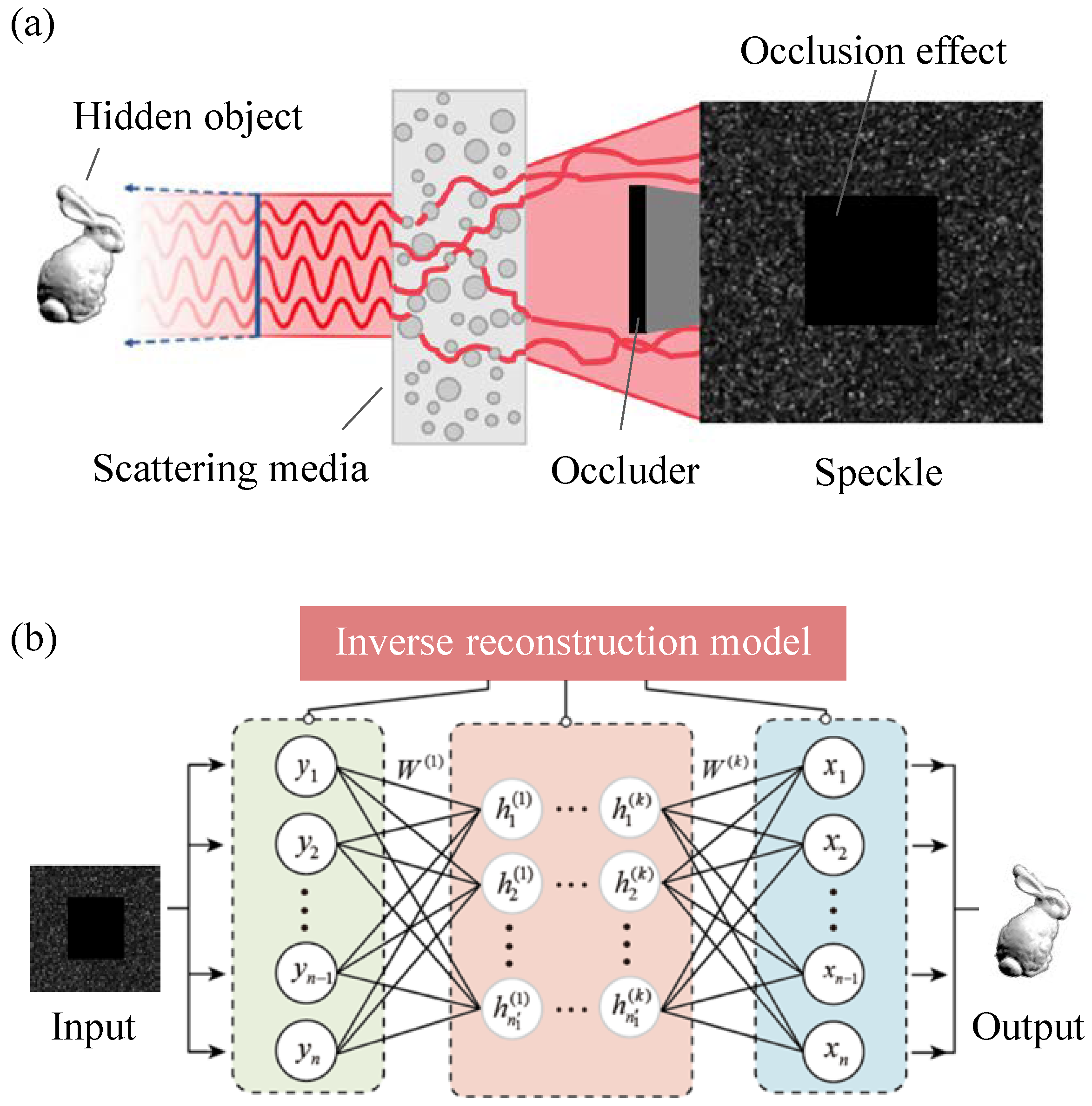
The main ideas underlying the proposed method are given as follows. In the NLOS scenarios shown in Figure 1a, the direct view of the object decreases due to the in-line opaque barriers. Generally speaking, for a incident wave field at the incident plane in such an NLOS imaging system, the corresponding wave filed at the output location can be described as Equation (1):
where is Green’s function [18] describing the transmission scattering mapping relation between incident location and detection location . represents the transmission matrix describing the occlusion effect caused by in-line-of-sight opaque barriers.
The recorded light intensity at output plane can de calculated using the output wave filed by:
Obviously, as seen from the Equation (2), the light intensity at position on the image plane is integral of a certain transformation of the entire illuminated object.
Owing to the scattering effect, the propagation direction of incident light changes randomly. Therefore, part of the incident light that should travel in a straight line and be occluded by in-line-of-sight opaque barriers still can be measured. That is, with the help of a scattering medium, the information of hidden objects that should be occluded and lost will be encoded in each pixel of the recorded speckle. According to the information transferred in scattering media which has been studied in theory [19,20], it is possible to recover the target from detected speckles even though speckles tend to have random distribution in spatial because of the light scattering. Moreover, because each part of the speckle involves information about the whole object plane, there is a potential for using an extremely small speckle block to reconstruct the object image.
Because the above-mentioned reconstruction process that recovers object images from detected degraded speckles can be regarded as an inverse problem, the problem that retrieves the target from a partial-covered speckle can be described as a well-known Tikhonov–Wiener optimization problem as follows:
where denotes the norm. In general, the first term expresses fitness, such as matching in the least-squares sense the measurement to the forward model for the original object. H expresses the transform operator characterizing the mapping relation between the captured pattern and ground truth I, and . is the regularizer function and tends to leverage prior knowledge to avoid the non-uniqueness of the ill-posed problem. is the regularization parameter. The optimization problem described in Equation (3) can be solved by pseudo-inverse solution, or its Moore–Penrose improvement [21] when setting as 0. The goal of this optimization problem is to minimize the difference between the estimation and the original object I.
When the forward operator in the above-mentioned reconstruction process is ill-posed or uncertain, the deep-learning-based approach has been proven to be especially attractive [22,23,24,25,26,27] while the common numerical method is out of work. In this work, inverse problems that recover object images from detected degraded speckles still can be solved using a deep learning network shown as in Figure 1b. As a data-driven algorithm, the deep learning model learns the forward operator H and regularizer function simultaneously in a non-explicit way.
The deep-learning-based reconstruction model conforms an encoder–decoder frame and the detailed network structure is given in Figure 2a. The left part acts as an encoder, which consists of four dense blocks connected by max-pooling layers for downsampling. As seen from Figure 2b, each dense block contains multiple layers, in which each layer consists of batch normalization (BN), the rectified linear unit (ReLU) non-linear activation function, and the convolution (conv) operator. The high-level feature is extracted layer by layer from the input speckle with the encoder process, which takes advantage of the down-sampling process to enhance robustness, avoid overfitting, and reduce computation load. The right part plays a role in the decoder by upsampling operation. During the upsampling process, the feature map of the encoder path is copied and cropped to the corresponding symmetrical decoder path to preserve high-frequency information. After the decoder path, an additional convolutional layer and a fully connected layer followed by the last layer produce the output. It should be noted that the number of downsampling layers and upsampling layers changes according to the input size. Specifically, the number of downsampling layers and upsampling layers should be decreased to guarantee that the is an integer when .
Our reconstruction model is designed to recover sparse objects. In order to train the model, the loss function is designed to measure differences between ground truths and predicted outputs. Here, the Negative Pearson correlation coefficient () [28] and the mean square error () are combined as the loss function.
The detailed loss functions are defined as follows:
where , , , , and represent the mean value of the original input I, the mean value of the predicted output , the size of inputs, and weight coefficient, respectively. In this work, is set as 0.001.
To train the network, 4500 speckle blocks of hidden objects are collected as training data. In addition, 300 speckle blocks are set as validation data and the remaining 200 speckle blocks are used as test data to test the trained model. Both test data and validation data are not included in the training data. During the training process, the initial learning rate is and the learning rate multiplies by 0.9 for every 10 epochs. The number of training epochs is 800 and the batch size is set as 50. The adopts adaptive moment estimation (Adam) is used to minimize the loss function to realize model convergence.
The training process of the scattering-assisted network is performed on a 7th generation i7 server with two graphics processing units (NVIDIA TITAN Xp) using TensorFlow with Python 3.6. In this work, the average reconstruction time of a hidden object is about 21 ms.
2.2. Experimental Setup
To demonstrate the ability of imaging around opaque barriers, a typical NLOS imaging system is designed as Figure 3. The direct line of sight between the DMD and camera is blocked by an opaque barrier. In addition, the area of scattering layers is larger than that of occlusion to ensure partial scattering light can be captured. In the experiment, a helium-neon laser (wavelength = 632.8 nm) is used to illuminate the DMD (DLC9500P24) where the surface displays objects from two different databases: MNIST (a public handwritten digits dataset) and EnglishHnd (a public handwritten English letters dataset). The VND and expander are used to control the illumination power and laser beam size, respectively. The light around the obstacle passes through a 4f lens system and is captured by a CCD where the center block with 512 × 512 pixels is used. During the experiment, various laminated black cardboards with different shapes and sizes are set as in-line opaque barriers. In addition, a ground glass diffuser with 220 grit is chosen to be the insertable scattering layer. Both distances from the DMD to the scattering medium and the scattering medium to the barrier are ∼10 cm.
Using the above experimental setup, the speckle where partial is covered by an occlusion can be captured. In general, it is extremely difficult for human vision to recognize the target directly from a random speckle, not to mention a partial-covered of that. However, as an effective method for feature extracting, it is feasible for the deep learning method to retrieve images utilizing the invariant information coded in speckles. Herein, according to the thought in Figure 1, partial-covered speckles can be put into a deep neural reconstruction network shown as Figure 2 to retrieve hidden-from-view objects.
3. Results and Discussion
3.1. Obstacle-Avoidance Imaging
First of all, to evaluate the obstacle-avoidance imaging ability of the proposed scattering-assisted method, the founding year, ‘1896’, and name abbreviation, ‘SJTU’, of Shanghai Jiao Tong University are used as targets shown in Figure 4a. In addition, these objects displayed on DMD are occluded by the barrier with a fixed shape as the area above the red dotted line in the first line of Figure 4a. For the sake of comparison, before inserting the scattering layer, the direct measurement results are also recorded. As seen from the second line of Figure 4a, the majority view is covered so that the captured information is too little for a human to identify directly. However, with the help of an extra scattering medium, the proposed method retrieves corresponding object images successfully, which can be seen in the 4th and 5th lines in Figure 4a. In contrast, the intensity map along the solid line of the ‘8’ and ‘S’ images is plotted in Figure 4b. Although the intensity result of the larger cropped area is closer to the ground truth (GT), the small block, 32 × 32 pixels, merely accounting for 0.39% () FoV of the camera, still works compared with direct measurement. It is worth mentioning that there is a data pre-processing for captured speckles before the image reconstruction process. From blocks in the 3rd line of Figure 4a, 32 × 32 and 128 × 128 blocks from the lower right corner of speckles are cropped respectively as network inputs instead of using the entire speckle, which is 512 × 512 pixels. On one hand, the cropped operation can reduce calculation costs since most areas of speckle are covered and the corresponding information of those is lost. On the other hand, success-reconstructed results using small cropped speckle blocks verify that each part of the speckle involves complete information about the hidden target and in turn clarify the feasibility of the scattering-assisted computational imaging method. In addition, when the collusion area changes, we can crop a small speckle block from the public remained view and then use the well-trained network to restore the object image from it, which validly avoids retraining the neural network due to the change of occlusion set. It is worth mentioning that, even if the recorded speckle is completely out of the target area, the proposed scattering-assisted method still can recover the image hidden from view using a remarkably small speckle.
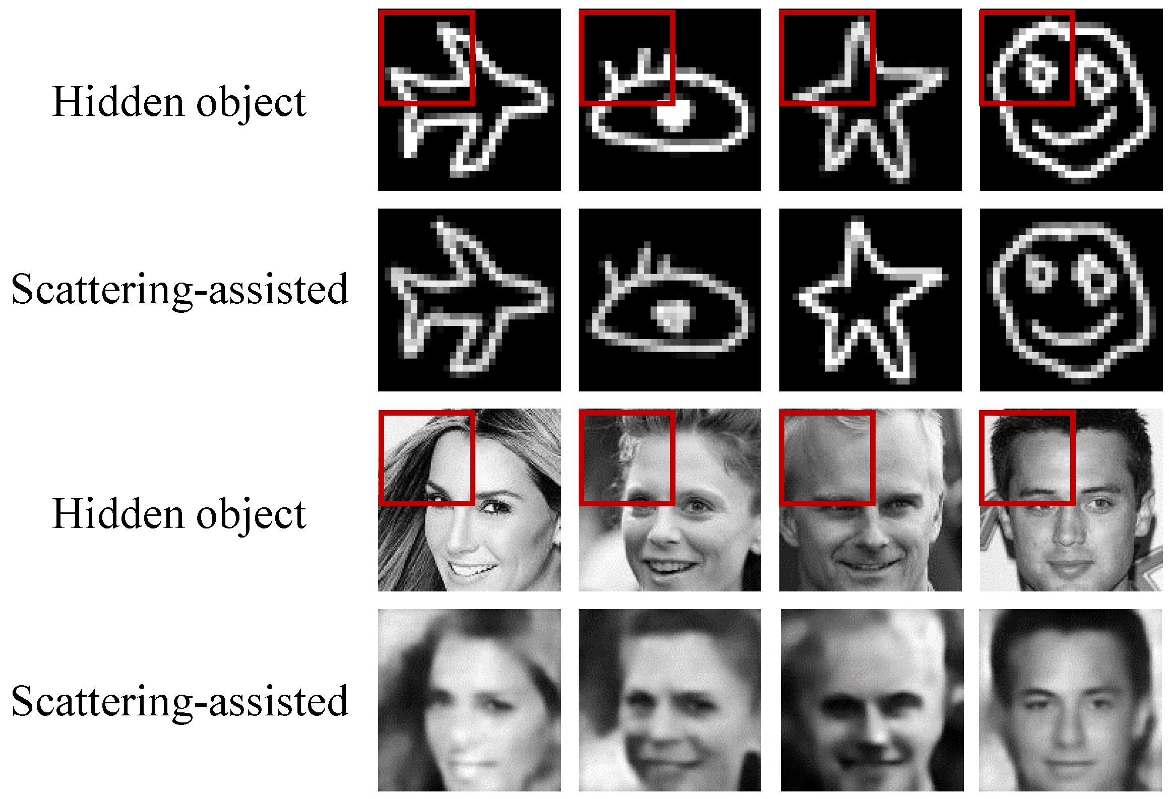
In addition, more complicated images like stick figures and faces are set as objects to perform scattering-assisted computational imaging. The corresponding results are shown in Figure 5, and the red box represents the remaining view due to the opaque barrier. The proposed method has great performance for eliminating the in-line occlusion effect in spatial sparse targets while failing to retrieve the detail feature in humans’ faces. In the future work, we will explore a more effective neural network architecture or a more powerful technique to improve the reconstruction performance for complicated non-sparse images.
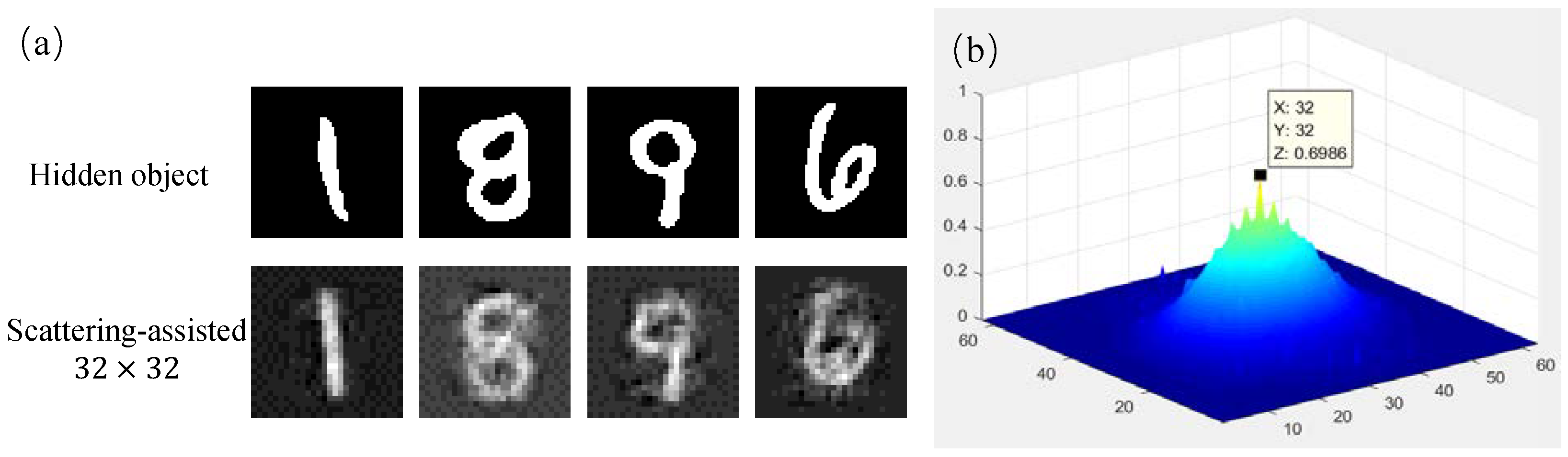
Moreover, we further explore the feasibility when using dynamic scattering medium to assist the obstacle-avoidance imaging. We use the turbid Intralipid solution and keep stirring the solution to create the dynamic scattering environment. In the imaging system with the dynamic scattering solution and the in-line opaque barrier, the partial-occluded speckles are collected through and then cropped as 32 × 32 blocks to train the network. The corresponding reconstruction results are given in Figure 6a. As seen from the result, though the reconstruction quality needs to be improved, and the proposed scattering-assisted computational imaging method still works when using a dynamic scattering medium, which demonstrates its practicality in the practical scenario. Different shots of the same object “1” are recorded through the dynamic solution and the correlation map between speckle blocks of two different 32 × 32 speckle shots is given in Figure 6b. According to our previous works [22,23], the correlation relationship between two speckle blocks from different shots of the same object guarantees the feasibility of using a single well-trained network model to reconstruct the hidden object from speckles collected under a dynamic scattering environment. In addition, we will make our best effort to improve the reconstruction quality under a dynamic scattering condition in future work.
3.2. Comparison
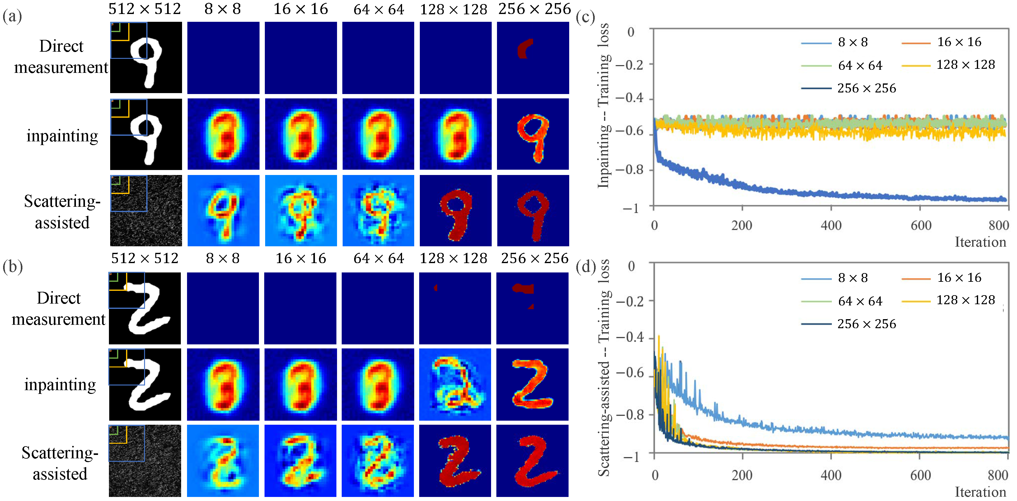
For further accessing the obstacle-avoidance imaging performance using the limited view, five settings with different occlusion proportions are explored in Figure 7. When different occlusions are set, only the upper left view of a camera with 8 × 8, 16 × 16, 64 × 64, 128 × 128 and 256 × 256 pixels remain. As a contrast, results of the direct measurement and image inpainting are given. The image inpainting [29,30] algorithm is a common computer vision technique utilizing the redundancy information of an incomplete direct measurement to remove covered parts in a visually plausible way. However, these methods usually fail to guarantee the unique optimal output when there is a larger-scale occlusion. Without the scattering medium, it is hard to identify the target from direct measurement results in the first row of Figure 7a,b because of insufficient information caused by the occlusion effect. First of all, the direct measurement is used by an image inpainting method to recover the object image. In addition, only when the view block is up to 256 × 256 pixels do image inpainting results seem close to the ground truth. However, the proposed method works until the direct in-line-of-sight scattering area is as little as 8 × 8 pixels, which means ∼0.024% of the entire view and approximately 99.976% occlusion proportion of direct sight. To quantitatively evaluate the performance, the NPCC value of each iteration for the proposed method is given in Figure 7d and that of the image inpainting method is in Figure 7c for comparison. For NPCC in the training process, the closer that value is to −1, the more well-trained the network is. When captured speckle block comes to 16 × 16 pixels which respond to approximately 0.097%() of the whole view, the scattering-assisted computational approach shows stable imaging performance. Meanwhile, until the speckle block comes to 256 × 256 pixels, the image inpainting network obtains great convergence, the speed of which is still slower than our method. There is no doubt that, for the transmission NLOS imaging scenarios, the proposed method is superior to a single image post-processing algorithm such as image inpainting because the scattering layer encodes the target information in the random speckle to guarantee the authenticity of reconstruction results and what image inpainting learns is just from the direct measurement where most target information is lost. As expected, the loss of the proposed method decreases concerning the visible block size until the value of NPCC nears −1. By the way, according to the set occlusion, the target is totally out of view when only the left upper blocks with 8 × 8 and 16 × 16 pixels are visible. In this case, the object is totally outside the view area where is a remarkably small speckle ratio(). That is, the proposed approach still works even when the target is out of sight as long as the scattered light can be captured. Therefore, with the assistance of scattering layers, the proposed method has great obstacle-avoidance imaging potential with a limited view even when the target is totally out of view.
3.3. Robustness Analysis
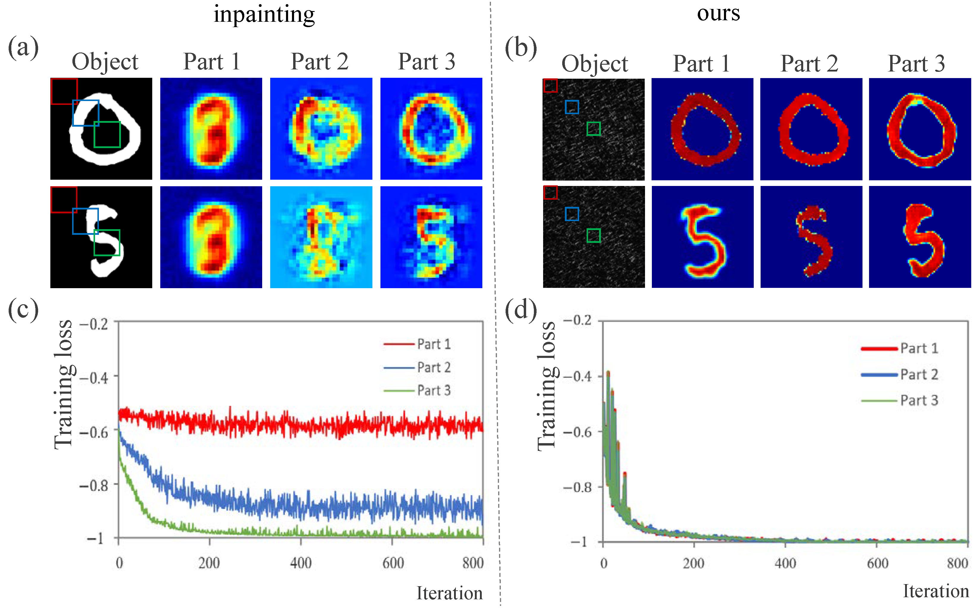
Figure 8a,b demonstrates the influence of occlusion positions, where three visible blocks of the same size are set as different-colored boxes show. In addition, corresponding results of digit ‘0’ are given as representative examples. The quantitative analysis is given in Figure 8c,d. For the inpainting method, when the selected visible region nears the central part, the loss of the inpainting method decreases obviously as Figure 8c shows, which is because the center tends to have richer target information than the corner. This clarifies that the position has a significant influence on the result of image inpainting. For our proposed method using speckle patterns, different occlusion positions have a little effect on reconstruction results as Figure 8d shows, implying that the method is viewing position-invariant. That is, our method not only performs well with the limited view but also is robust to the occlusion positions.
3.4. Generalization Analysis
Moreover, we further discuss the generalization performance of a single scattering-assisted network model when the position of the opaque barrier changes. We change the remaining view described as the solid box with 128 × 128 pixels and use the corresponding speckle block to train the reconstruction model, and then move the window along the direction of the arrow to crop the speckle as the test data. The movement distances are separately set as 0, 5, 10, 15, 20, 25, and 30 pixels. As seen from the result in Figure 9, the longer the movement distance is, the lower the image quality is. However, when the movement distance of the remaining view is under 10 pixels, the single well-trained model still can retrieve the high-quality image of the hidden object from the speckle block. Therefore, the proposed scattering-assisted computational imaging method is reasonably robust against the small change in the occlusion position caused by the camera jitter and other disturbances, performing great generalization performance and feasibility in practical obstacle-avoidance applications.
3.5. Photon-Limited Demonstration
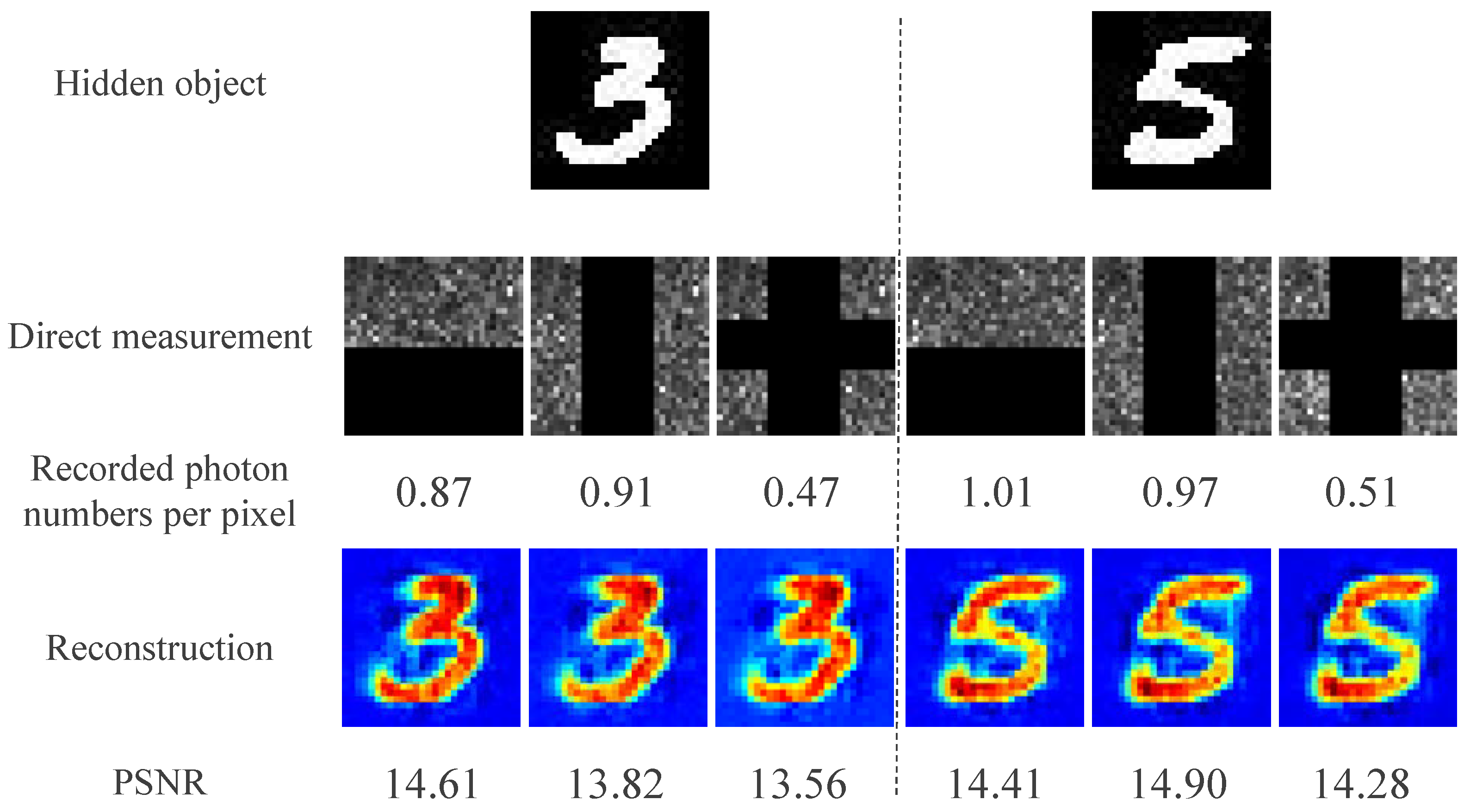
Moreover, in view of the photon-limited illumination condition in the practical imaging scenarios, extending the scope of our current work to photon-limited imaging for hidden objects is also of considerable interest. In the experiment, the number of detected photons remains at a single-photon level by decreasing the incident light power. For convenience, to record the number of photons and clarify the photon-limited application, the single-photon counting camera (SPC) is used as the camera in Figure 3. In addition, the corresponding result of potential in photon-limited imaging is demonstrated in Figure 10. Meanwhile, the avoidance-obstacle imaging performance of different occlusion shapes has been explored simultaneously. The reconstruction results in Figure 10 show that the proposed scattering-assisted method can recover the image from speckles with different occlusion shapes, verifying the feasibility of imaging around the different opaque. Even more to the point, as little as 0.47 photons per pixel are required to retrieve the target, ’3’, demonstrating the powerful ability of imaging around opaque barriers in photon-limited illumination conditions. Combining with results in Figure 7, it is possible to use a part of the speckle collected at the photon-limited illumination condition to recover the image of hidden objects. Thus, the total number of photons required to recover the hidden object can be further reduced by cutting the recorded photon-limited speckle as a smaller block.
4. Conclusions
In conclusion, we present a scattering assisted computational imaging method for objects hidden behind opaque obstacles. With the assistance of a scattering medium, the deep-learning-based computational method performs imaging using remarkably small speckle blocks, significantly broadening the view and overcoming the influence of in-line-of-sight occlusions. It is demonstrated that the hidden object can be recovered from speckle blocks even when the object itself is totally out of view. Compared to the common NLOS imaging requiring the reflected wall and ToF technique, the proposed method only needs a remarkably small block of speckle captured by a ordinary digital camera and an in-line “plug and play” scattering medium such as fogs, which is more cost-effective and accessible in the wild. Furthermore, the method not only is robust and applicable to various in-line occlusions with different shapes and positions without any calibration operations, but also can be extended to the photon-limited imaging application while only a few photons can be detected, making it desirable for avoidance-obstacle imaging and covert imaging in a number of real-life scenarios, such as surveillance, rescue missions and tracking incoming hidden adversaries in real-time.
Author Contributions
Conceptualization, Y.S., X.W., J.S. and G.Z.; methodology, Y.S.; validation, Y.S.; formal analysis, Y.S. and X.W.; investigation, Y.S.; writing—original draft preparation, Y.S.; writing—review and editing, Y.S. and X.W.; visualization, Y.S.; supervision, G.Z. and X.W. All authors have read and agreed to the published version of the manuscript.
Funding
The National Natural Science Foundation of China (61471239, 61631014, 61905140); Hi-Tech Research and Development Program of China (2013AA122901).
Institutional Review Board Statement
Not applicable.
Informed Consent Statement
Not applicable.
Data Availability Statement
The data that support the findings of this study are available from the corresponding author upon reasonable request.
Conflicts of Interest
The authors declare no conflict of interest.
References
- Gariepy, G.; Tonolini, F.; Henderson, R.; Leach, J.; Faccio, D. Detection and tracking of moving objects hidden from view. Nat. Photonics 2016, 10, 23–26. [Google Scholar] [CrossRef]
- O’Toole, M.; Lindell, D.B.; Wetzstein, G. Confocal non-line-of-sight imaging based on the light-cone transform. Nature 2018, 555, 338–341. [Google Scholar] [CrossRef] [PubMed]
- Hu, Q.; Xu, S.; Chen, X.w.; Wang, X.; Wang, K.X. Object recognition for remarkably small field-of-view with speckles. Appl. Phys. Lett. 2021, 118, 091103. [Google Scholar] [CrossRef]
- Faccio, D.; Velten, A.; Wetzstein, G. Nonline-of-sight imaging. Nat. Rev. Phys. 2020, 2, 318–327. [Google Scholar] [CrossRef]
- Wu, C.; Liu, J.; Huang, X.; Li, Z.P.; Yu, C.; Ye, J.T.; Zhang, J.; Zhang, Q.; Dou, X.; Goyal, V.K.; et al. Non–line-of-sight imaging over 1.43 km. Proc. Natl. Acad. Sci. USA 2021, 118, e2024468118. [Google Scholar] [CrossRef] [PubMed]
- Velten, A.; Willwacher, T.; Gupta, O.; Veeraraghavan, A.; Bawendi, M.G.; Raskar, R. Recovering three-dimensional shape around a corner using ultrafast time-of-flight imaging. Nat. Commun. 2012, 3, 1–8. [Google Scholar] [CrossRef]
- Zhu, Y.; Li, J. NLOS Imaging Assisted Navigation for BVI. In Proceedings of the 2nd International Workshop on Human-centric Multimedia Analysis, online, 12 October 2021; pp. 23–30. [Google Scholar]
- Saunders, C.; Murray-Bruce, J.; Goyal, V.K. Computational periscopy with an ordinary digital camera. Nature 2019, 565, 472–475. [Google Scholar] [CrossRef]
- Singh, A.K.; Naik, D.N.; Pedrini, G.; Takeda, M.; Osten, W. Looking through a diffuser and around an opaque surface: A holographic approach. Opt. Express 2014, 22, 7694–7701. [Google Scholar] [CrossRef]
- Jiao, A.; Tsang, P.W.M.; Poon, T.C. Restoration of digital off-axis Fresnel hologram by exemplar and search based image inpainting with enhanced computing speed. Comput. Phys. Commun. 2015, 193, 30–37. [Google Scholar] [CrossRef]
- Xia, H.; Montresor, S.; Guo, R.; Li, J.; Olchewsky, F.; Desse, J.M.; Picart, P. Robust processing of phase dislocations based on combined unwrapping and inpainting approaches. Opt. Lett. 2017, 42, 322–325. [Google Scholar] [CrossRef]
- Zhu, S.; Guo, E.; Gu, J.; Bai, L.; Han, J. Imaging through unknown scattering media based on physics-informed learning. Photonics Res. 2021, 9, B210–B219. [Google Scholar] [CrossRef]
- Han, Q.; Zhao, W.; Zhai, A.; Wang, Z.; Wang, D. Optical encryption using uncorrelated characteristics of dynamic scattering media and spatially random sampling of a plaintext. Opt. Express 2020, 28, 36432–36444. [Google Scholar] [CrossRef] [PubMed]
- Zhou, L.; Xiao, Y.; Chen, W. Learning-based optical authentication in complex scattering media. Opt. Lasers Eng. 2021, 141, 106570. [Google Scholar] [CrossRef]
- Choi, Y.; Yang, T.D.; Fang-Yen, C.; Kang, P.; Lee, K.J.; Dasari, R.R.; Feld, M.S.; Choi, W. Overcoming the diffraction limit using multiple light scattering in a highly disordered medium. Phys. Rev. Lett. 2011, 107, 023902. [Google Scholar] [CrossRef] [PubMed]
- Katz, O.; Ramaz, F.; Gigan, S.; Fink, M. Controlling light in complex media beyond the acoustic diffraction-limit using the acousto-optic transmission matrix. Nat. Commun. 2019, 10, 1–10. [Google Scholar] [CrossRef]
- Antipa, N.; Kuo, G.; Heckel, R.; Mildenhall, B.; Bostan, E.; Ng, R.; Waller, L. DiffuserCam: Lensless single-exposure 3D imaging. Optica 2018, 5, 1–9. [Google Scholar] [CrossRef]
- Devaney, A.J.; Marengo, E.A.; Gruber, F.K. Time-reversal-based imaging and inverse scattering of multiply scattering point targets. J. Acoust. Soc. Am. 2005, 118, 3129–3138. [Google Scholar] [CrossRef]
- Ishimaru, A. Wave Propagation and Scattering in Random Media; Academic Press: New York, NY, USA, 1978; Volume 2. [Google Scholar]
- Byrnes, N.; Foreman, M.R. Universal bounds for imaging in scattering media. New J. Phys. 2020, 22, 083023. [Google Scholar] [CrossRef]
- Penrose, R. A generalized inverse for matrices. In Mathematical Proceedings of the Cambridge Philosophical Society; Cambridge University Press: Cambridge, UK, 1955; Volume 51, pp. 406–413. [Google Scholar]
- Sun, Y.; Wu, X.; Zheng, Y.; Fan, J.; Zeng, G. Scalable non-invasive imaging through dynamic scattering media at low photon flux. Opt. Lasers Eng. 2021, 144, 106641. [Google Scholar] [CrossRef]
- Sun, Y.; Shi, J.; Sun, L.; Fan, J.; Zeng, G. Image reconstruction through dynamic scattering media based on deep learning. Opt. Express 2019, 27, 16032–16046. [Google Scholar] [CrossRef]
- Chen, T.; Lu, T.; Song, S.; Miao, S.; Gao, F.; Li, J. A deep learning method based on U-Net for quantitative photoacoustic imaging. In Photons Plus Ultrasound: Imaging and Sensing 2020; International Society for Optics and Photonics: San Francisco, CA, USA, 2020; Volume 11240, p. 112403V. [Google Scholar]
- Liu, S.; Meng, X.; Yin, Y.; Wu, H.; Jiang, W. Computational ghost imaging based on an untrained neural network. Opt. Lasers Eng. 2021, 147, 106744. [Google Scholar] [CrossRef]
- Wang, H.; Lyu, M.; Situ, G. eHoloNet: A learning-based end-to-end approach for in-line digital holographic reconstruction. Opt. Express 2018, 26, 22603–22614. [Google Scholar] [CrossRef] [PubMed]
- Situ, G. Learning to image through dense scattering media. In JSAP-OSA Joint Symposia; Optical Society of America: Washington, DC, USA, 2021; p. 12p_N404_6. [Google Scholar]
- Li, Y.; Xue, Y.; Tian, L. Deep speckle correlation: A deep learning approach toward scalable imaging through scattering media. Optica 2018, 5, 1181–1190. [Google Scholar] [CrossRef]
- Elharrouss, O.; Almaadeed, N.; Al-Maadeed, S.; Akbari, Y. Image inpainting: A review. Neural Process. Lett. 2020, 51, 2007–2028. [Google Scholar] [CrossRef]
- Qin, Z.; Zeng, Q.; Zong, Y.; Xu, F. Image inpainting based on deep learning: A review. Displays 2021, 69, 102028. [Google Scholar] [CrossRef]
Figure 1.
Sketch map of scattering-assisted imaging across in-line-of-sight opaque barriers. (a) the scattering-assisted imaging system. (b) the inverse reconstrcution model.
Figure 1.
Sketch map of scattering-assisted imaging across in-line-of-sight opaque barriers. (a) the scattering-assisted imaging system. (b) the inverse reconstrcution model.

Figure 2.
Detailed architecture of the neural network. (a) structure of the reconstruction model; (b) structure of the dense block.
Figure 2.
Detailed architecture of the neural network. (a) structure of the reconstruction model; (b) structure of the dense block.

Figure 3.
Detailed experimental setup. (VND: variable neutral density filter; DMD: digital micro-mirror device; L1: 300 mm lens; L2: 150 mm lens; F1: pinhole).
Figure 3.
Detailed experimental setup. (VND: variable neutral density filter; DMD: digital micro-mirror device; L1: 300 mm lens; L2: 150 mm lens; F1: pinhole).

Figure 4.
(a) The result of hidden object with both direct imaging and proposed scattering-assisted computational imaging method; (b) intensity plots from one line of objects corresponding to the intensity of ground truths (GT), where (i)–(ii) respond to the imaging results of ‘8’ using blocks with 32 × 32 and 128 × 128 pixels, respectively, and (iii)–(iv) respond to these of ‘S’.

Figure 5.
The scattering-assisted computational imaging result of complicated objects.

Figure 6.
The performance of a single well-trained model with the dynamic scattering medium. (a) reconstruction results; (b) correlation between different shots of same object “1”.
Figure 6.
The performance of a single well-trained model with the dynamic scattering medium. (a) reconstruction results; (b) correlation between different shots of same object “1”.

Figure 7.
Results for comparative experiments. (a) the corresponding results of digits ’9’ with different in-line-of-sight areas; (b) the corresponding results of ’2’ with different in-line-of-sight areas; (c) the loss (NPCC between outputs and ground truths) for different block sizes with training iterations of the inpainting algorithm; (d) the loss for different block sizes of the proposed method.

Figure 8.
Demonstration on the position robustness performance for both image inpainting (a) and the proposed method (b). The loss with training iterations of the image inpainting (c) and proposed method (d).
Figure 8.
Demonstration on the position robustness performance for both image inpainting (a) and the proposed method (b). The loss with training iterations of the image inpainting (c) and proposed method (d).

Figure 9.
The generalization performance of scattering-assisted computational imaging method. (a) the sketch map of changing the remaining view; (b) the reconstruction results using a single well-trained network model; quantitative analyses of image quality on (c) correlation and (d) PSNR.
Figure 9.
The generalization performance of scattering-assisted computational imaging method. (a) the sketch map of changing the remaining view; (b) the reconstruction results using a single well-trained network model; quantitative analyses of image quality on (c) correlation and (d) PSNR.

Figure 10.
The avoidance–obstacle performance for different occlusion shapes of the proposed method under the photon-limited condition.
Figure 10.
The avoidance–obstacle performance for different occlusion shapes of the proposed method under the photon-limited condition.

Publisher’s Note: MDPI stays neutral with regard to jurisdictional claims in published maps and institutional affiliations. |
© 2022 by the authors. Licensee MDPI, Basel, Switzerland. This article is an open access article distributed under the terms and conditions of the Creative Commons Attribution (CC BY) license (https://creativecommons.org/licenses/by/4.0/).
Share and Cite
MDPI and ACS Style
Sun, Y.; Wu, X.; Shi, J.; Zeng, G. Scattering-Assisted Computational Imaging. Photonics 2022, 9, 512. https://doi.org/10.3390/photonics9080512
AMA Style
Sun Y, Wu X, Shi J, Zeng G. Scattering-Assisted Computational Imaging. Photonics. 2022; 9(8):512. https://doi.org/10.3390/photonics9080512
Chicago/Turabian StyleSun, Yiwei, Xiaoyan Wu, Jianhong Shi, and Guihua Zeng. 2022. "Scattering-Assisted Computational Imaging" Photonics 9, no. 8: 512. https://doi.org/10.3390/photonics9080512
Note that from the first issue of 2016, this journal uses article numbers instead of page numbers. See further details here.