Numerical Analysis of Optical Trapping Force Affected by Lens Misalignments


1
State Key Laboratory of Modern Optical Instrumentation, College of Optical Science and Engineering, Zhejiang University, Hangzhou 310027, China
2
Quantum Sensing Center, Zhejiang Lab, Hangzhou 311121, China
*
Author to whom correspondence should be addressed.
Photonics 2021, 8(12), 548; https://doi.org/10.3390/photonics8120548
Submission received: 18 November 2021
/
Revised: 27 November 2021
/
Accepted: 29 November 2021
/
Published: 2 December 2021
(This article belongs to the Special Issue Optomechanics: Science and Applications)
Abstract
:Geometrical optics approximation is a classic method for calculating the optical trapping force on particles whose sizes are larger than the wavelength of the trapping light. In this study, the effect of the lens misalignment on optical force was analyzed in the geometrical optics regime. We used geometrical optics to analyze the influence of off-axis placement and the tilt of the lens on the trapping position and stiffness in an optical trap. Numerical calculation results showed that lens tilting has a greater impact on the optical trap force than the off-axis misalignments, and both misalignments will couple with each other and cause a shift of the equilibrium point and the asymmetry of the optical trap stiffness in different ways. Our research revealed the asymmetry in optical traps caused by lens misalignment and can provide guidance for optimize lens placement in future experiments.
1. Introduction
Optical tweezers have attracted wide attention due to their unique ability to manipulate tiny objects. Since Ashkin completed the pioneering work of capturing particles [1], optical tweezers have found broad application prospects in many fields ranging from biology [2,3,4] to surface plasmons [5], microparticle and nanoparticle manipulation [6,7,8], macroscopic quantum physics [9], and fundamental physics [10,11]. Optical tweezers in high vacuum play a significant role in ultra-precision measurement owing to their unique characteristics [12]. Among them, an increase in the sensitivity of acceleration measurement will help the study of forces related to mass or the number of atoms or nucleons in a sphere or millicharged dark matter particles [13]. The single-beam optical trap structure can be used to achieve a high-sensitivity acceleration measurement, and this acceleration measurement would be preferable for large-volume microspheres since the larger the microsphere, the higher the signal-to-noise ratio [14,15]. There are currently three different calculation methods based on the particle size in comparison with the laser wavelength. The first is the generalized Lorenz–Mie theory [16], which is a rigorous calculation method based on Maxwell’s equations [17]. The second is the Rayleigh regime, which is a method for calculating the optical trapping force mainly used for nanospheres that can be regarded as electric dipoles [18,19]. The last is the geometrical optics method suitable for calculating larger particles [20], which is the focus of our article.
The geometrical optics theory is based on the conservation of momentum: the optical force is equal to the change in the momentum flux of the trapping light. This idea has been used by Ashkin to explain the trapping forces on a dielectric sphere [21], and the related computational toolbox for optical tweezers in geometrical optics has also been developed [22]. However, the actual lens has aberrations, and the aberrations will have a significant impact on the optical trapping force [23,24]. Therefore, there is still room for further improvement of the ray optics method for analyzing the actual trapping force. For this reason, the calculation of the optical trapping force in this study does not use the traditional ideal lens model but uses the real lens model combined with the real ray tracing mode in Zemax [25]. This study will focus on exploring the influence of lens misalignments in a real optical tweezer setup.
Although optical tweezers are a practical and novel technology, they are hampered by installation imperfections, as are other precise optical systems. Specifically, even without considering the polarization state of the trapping light, some unexpected phenomena such as the detection coupling within axes [26] and difference of x, y-axes resonant frequencies [12] may occur due to misalignment of the lens, so the influence of lens mounting on experiments is worth discussing. To investigate in detail the force changes associated with the lens misalignment, we combine the ray optics method and ray tracing function in single-beam optical trap. Furthermore, we take advantage of this new application of ray optics to explore the effect of misalignment on the optical trap force curve and the stiffness of the optical trap. This study mainly considers two types of placement errors, which are off-axis and tilt from lens. Corresponding changes of the optical trap force curve and the optical trap stiffness are, respectively, provided. To evaluate the actual misalignment to the maximum extent possible, we have considered a situation in which the x- and y-axes have imperfect placement at the same time and drawn surface diagrams of the optical trap stiffness on a two-dimensional (2D) plane. Our work can explain the asymmetry and increased non-linear effect of the radial stiffness of the optical trap in the experiment. Furthermore, our results may be helpful for improving lens placement accuracy in future experiments.
2. Geometrical Optics Theory and Model in Optical Tweezers
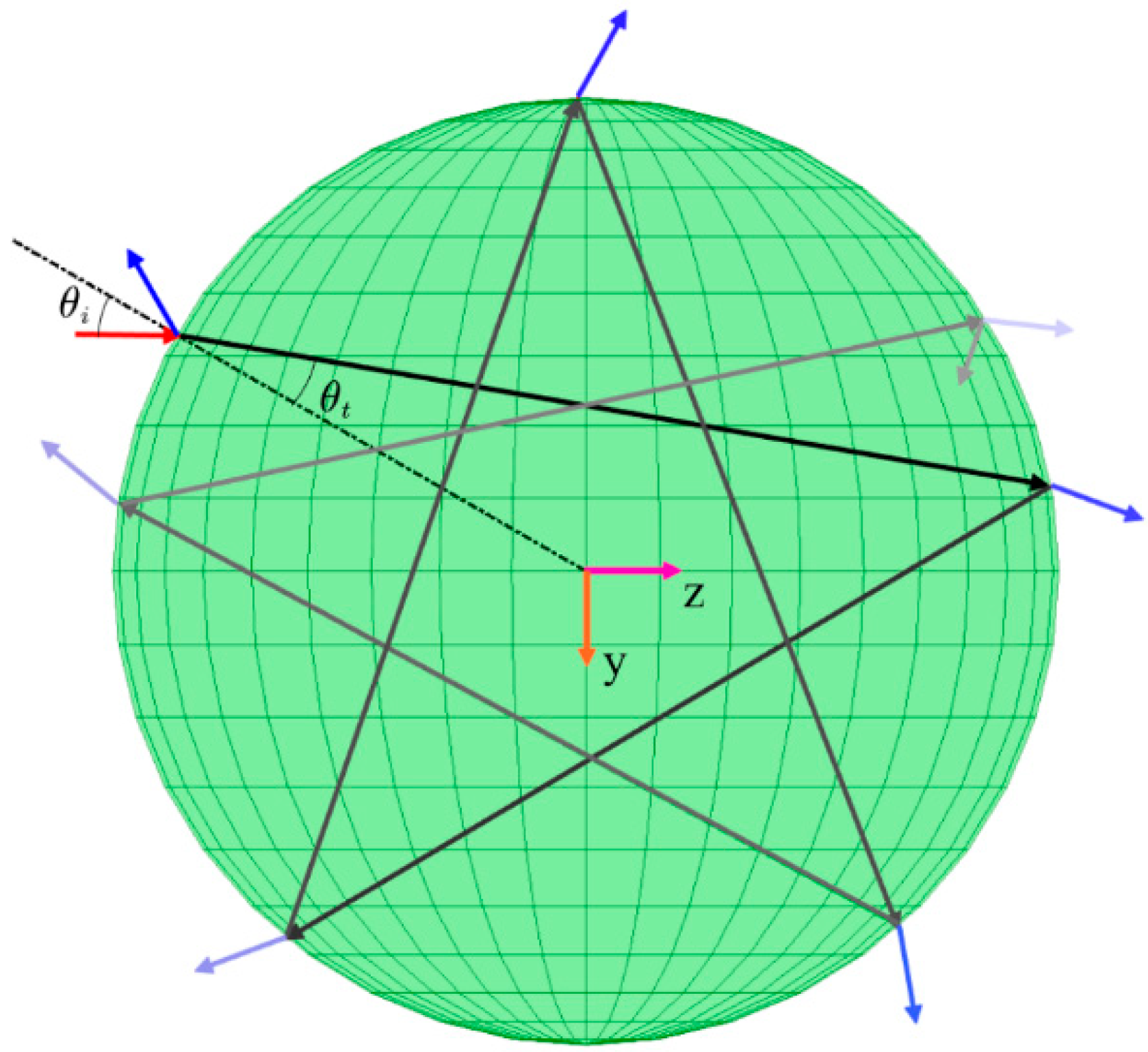
The geometrical optics method is suitable for calculating the optical trapping force received by the relatively large microsphere [21] since the diffraction effect of light can be ignored when the microsphere’s diameter is significantly larger than the light wavelength. Under such conditions, the Gaussian beam can be decomposed into a series of rays. Each ray is endowed with an appropriate light intensity according to the distance from its position to the center of the beam in order to ensure that the intensity profile of the laser beam is still as the Gaussian distribution. At the same time, it should be ensured that the polarization state is consistent with that before decomposition. We first consider a single ray impinging from a medium with the refractive index on a dielectric sphere with the refractive index . Since the refractive index of the microsphere is different from that of the surrounding environment, light will be transmitted and reflected at the same time when it strikes the surface of the microsphere. The energy distribution of the reflected and transmitted lights follows the Fresnel formula. Under the condition of circular polarization, the reflection and transmission coefficients can be written as [22]:
Here, represents the angle of incidence light, and represents the angle of refraction light. In addition, they have a relation of .
The light transmitted into the microsphere will be retransmitted and reflected when it hits the microsphere’s surface. In addition, when the light is reflected back to the microsphere, it undergoes the same scattering event as it travels to the boundary. The same process will continue to occur until there is no reflected light from the microsphere boundary, as shown in Figure 1, which was drawn with the computational toolbox for optical tweezers [22].
Since the light’s propagation direction and speed will change when it is reflected and transmitted on the microsphere’s surface, the momentum of the light decreases accordingly. The momentum of the microsphere will also change due to the momentum conservation of the system (that is, the microsphere is subjected to force). The light force in each scattering event is accumulated, and the sum of the results can be written as follows [20]:
Here P denotes the power of the incident light, which is proportional to the distance from the position of the light to the axis of symmetry of the Gaussian beam; and c represents the speed of light in a vacuum. R and T represent the optical power reflection and transmission coefficients, which can be calculated from Equations (1) and (2), respectively, under the condition of circularly polarized light. At the same time, the representation of the incident angle and refraction angle must follow the symbolic rule in geometrical optics, that is, the right-hand rule. So, in Figure 1, according to the rule.
Note that Equations (3) and (4) are only correct when the particle shape is spherical. In both equations, represents the force whose acting direction is parallel to the propagation direction of the incident light, and this force is a non-conservative force. represents the force whose acting direction is perpendicular to the propagation direction of the incident light, which is a conservative force.
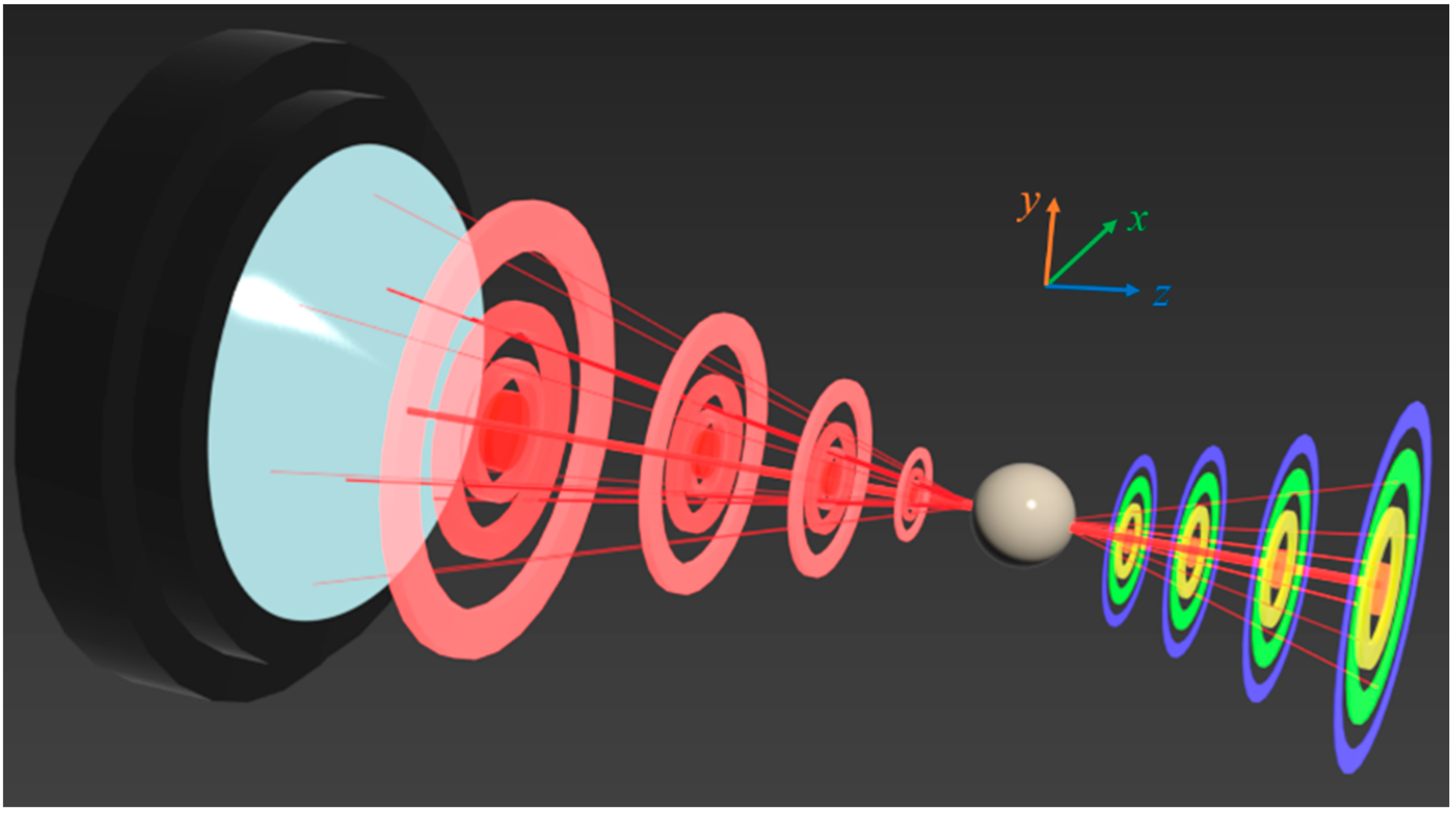
The total optical trapping force acting on the microsphere is obtained by vector superposition of the light force of each ray. We only need to know the angle of each ray entering the microsphere, and the corresponding cosine of the normal direction of the microsphere surface to calculate the optical trapping force exerted by the focused beam (Equations (3) and (4)). Thus, we can build the force calculation model of optical tweezers in geometrical optics, as shown in Figure 2.
In the model depicted in Figure 2, the Gaussian beam is assumed to pass through the telescope system to achieve beam expansion before entering the lens. Since the divergence angle of the Gaussian beam after beam expansion is small, it can be approximated as a plane wave.
Therefore, it is reasonable to discretize the Gaussian beam in front of the lens into a certain number of rays and assign appropriate power according to their location to ensure that the power profile of the optical field still has a Gaussian distribution. In this way, we ensure that every single ray that is bent by the lens has an appropriate power. According to the parameters of the real lens, the analytical equation of the bent ray can be obtained in the coordinate system shown in Figure 2. Moreover, combining the artificially set microsphere center position and diameter, we can easily write the corresponding spherical equation. Consequently, the incident point and incident angle of each ray on the microsphere can be obtained, and the total optical trapping force can be obtained by repeatedly using Equations (3) and (4) and accumulating the results. The total optical trapping force calculated by the model can still be decomposed into scattering and gradient forces, as the optical force generated by a single ray. The existence of gradient force will introduce stiffness, which can be expressed as , where represents the displacement of the microsphere in the optical trap. Only if is negative can microspheres be stably captured by the optical trap.
To account for the effects of aberrations such as spherical aberration and astigmatism, we used a real lens parameter that can be read with Zemax (instead of an ideal Gaussian model which only considers a numerical aperture parameter). At the same time, Zemax’s real ray tracing function can obtain the incident angle and other parameters of each ray impinging on the sphere. In this study, we used the optical tweezers calculation model to focus on solving the problem of optical force change induced by lens placement errors.
3. Numerical Calculation Results
3.1. Simulation Parameters
We explored a new application of the ray optics model of optical trapping force in analyzing lens misalignments. The Gaussian beam modes mentioned in this study are all fundamental modes. Unless otherwise indicated, the relevant calculation parameters described here remained the same throughout the analysis. The waist radius of a Gaussian beam with a wavelength of 780 nm is 2.5 mm (denoted as in this study). And the waist radius in the focal plane is 1.99 μm. The total laser power is 1 W. The diameter of the microspheres we use is 10 μm. Taking into account the wavelength-refractive dependence [27], we set the refractive index of the microsphere made of silica to 1.45. The real lens model used in this study is an aspheric plano-convex lens with a numerical aperture of 0.25. In addition, we define the z-direction in the coordinate system as the direction of gravity, so that gravity can be used to cancel the scattering force to achieve stable capture.
3.2. Verification of Accuracy
First, the accuracy of the simulation method described above should be evaluated. To illustrate the validity of our model, we use two different simulation methods to verify each other. The first calculation method, as mentioned above, introduces the lens parameters into the optical design software Zemax and uses the ray tracing function of the model to obtain the incident angle on the microsphere and other parameters for the calculation. We define this regime as the Zemax method. In the second method, we consider an ideal process (that is, the Gaussian beam focused by an ideal lens is transformed into one with a smaller waist radius instead of a series of rays pointing to the focal point). The ray direction in the calculation model is replaced by the normal direction of the equiphase surface of the Gaussian beam after lens transformation. The power of each ray is determined by the position of the incident point on the microsphere captured in the optical field. We define the second method as the traditional method.
In our simulation, a Gaussian beam propagates along the z-axis, as shown in Figure 2. The optical trapping force parallel to the z-axis is defined as a longitudinal force, and the one perpendicular to the z-axis is defined as a transverse force. In calculating the longitudinal force, we set the focal point of the lens as the origin of the coordinate system. In calculating the transverse force, we set the origin of the coordinate system at 100 to the right of the lens focus in Figure 2. Due to the symmetry, there is no transverse force when the microsphere moves along the z-axis, and there is also no optical force along the y-axis when it moves along the x-axis. The first step is to mutually validate the Zemax and traditional methods.
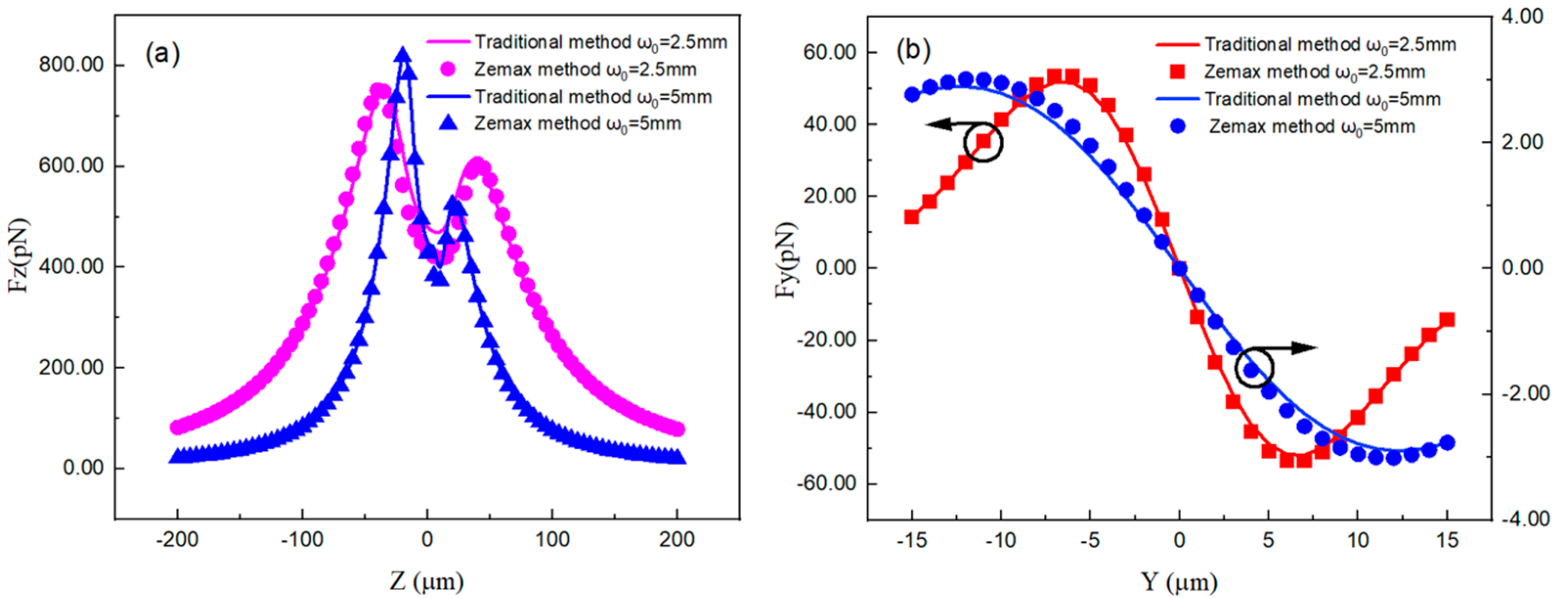
Figure 3 shows the comparison of the longitudinal force and transverse force received by the microspheres. The consistent results indicate that using Zemax method to perform ray tracing to obtain the angle and point of incidence is reliable. The discrepancy between the two calculation results near the point Z = 0 in Figure 3a can be explained by the different expression near the Gaussian beam waist. In the Zemax method, the beam waist is focused with no size, while the Gaussian beam waist has a certain size in traditional method. Hence, most differences between the two methods occur near the focal point, and the calculation results of the longitudinal force at the far field tend to be consistent. For further verification, we calculated the transverse force of the optical trap using two methods at Z = 100 μm. As shown in Figure 3b, the results of the two methods were consistent.
Importantly, the properties of the optical trapping force reflected by the two methods are consistent. For micron-sized sphere, the longitudinal force on the z-axis is always above zero, indicating that with the parameters used in the simulation, additional means are required to keep the microspheres levitated along z-axis, such as using gravity to balance the longitudinal force. The transverse force is always directed toward the center of the beam center, indicating that it is a radial restoring force and is the basis for the microspheres to be stably trapped. At the same time, the beam waist of the incident beam has a greater influence on the transverse force. When it changes from 2.5 to 5 mm, the transverse force on the microsphere decreases by an order of magnitude. After verifying the reliability of Zemax, we began to investigate the optical tweezer forces on a particle moving in two dimensions.
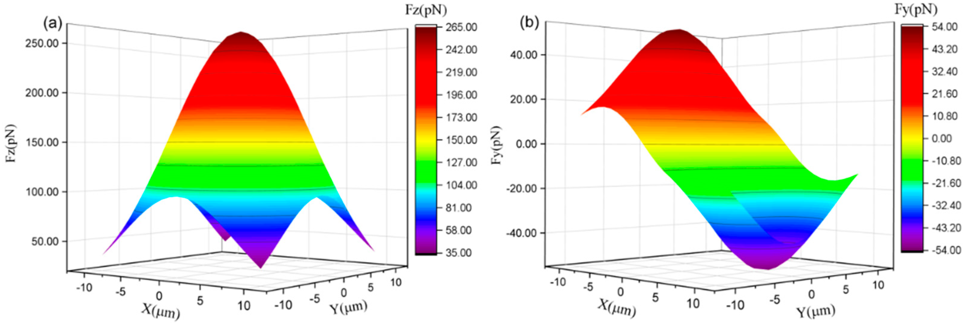
Figure 4 illustrates the forces exerted on the microsphere when it is moving across the cross-section of the optical trap. Owing to the symmetry, Figure 4a only shows the force exerting on the microsphere in the x-axis direction. Figure 4a shows that when the microsphere deviates from the point X = 0, the restoring force received by it is opposite to its motion direction. With its deviation on the y-axis, the absolute value of the restoring force Fx exerted on it will decrease. Figure 4b indicates that in the same cross-section of the beam, the longitudinal force on the optical axis is the largest, and the farther away the microsphere is from the optical axis, the less the longitudinal force it receives.
3.3. Lens Off-Axis Simulation
As mentioned earlier, one advantage of using Zemax’s real ray tracing function for optical trapping simulations is that the lens misalignment in the system can be analyzed. Here, we investigate the effects of lens eccentricity and tilting on the equilibrium position and stiffness of the transverse force. To be consistent with the preceding discussion, we still choose the point of Z = 100 μm, a possible stable trap point, to analyze the mechanical properties of the optical trap.
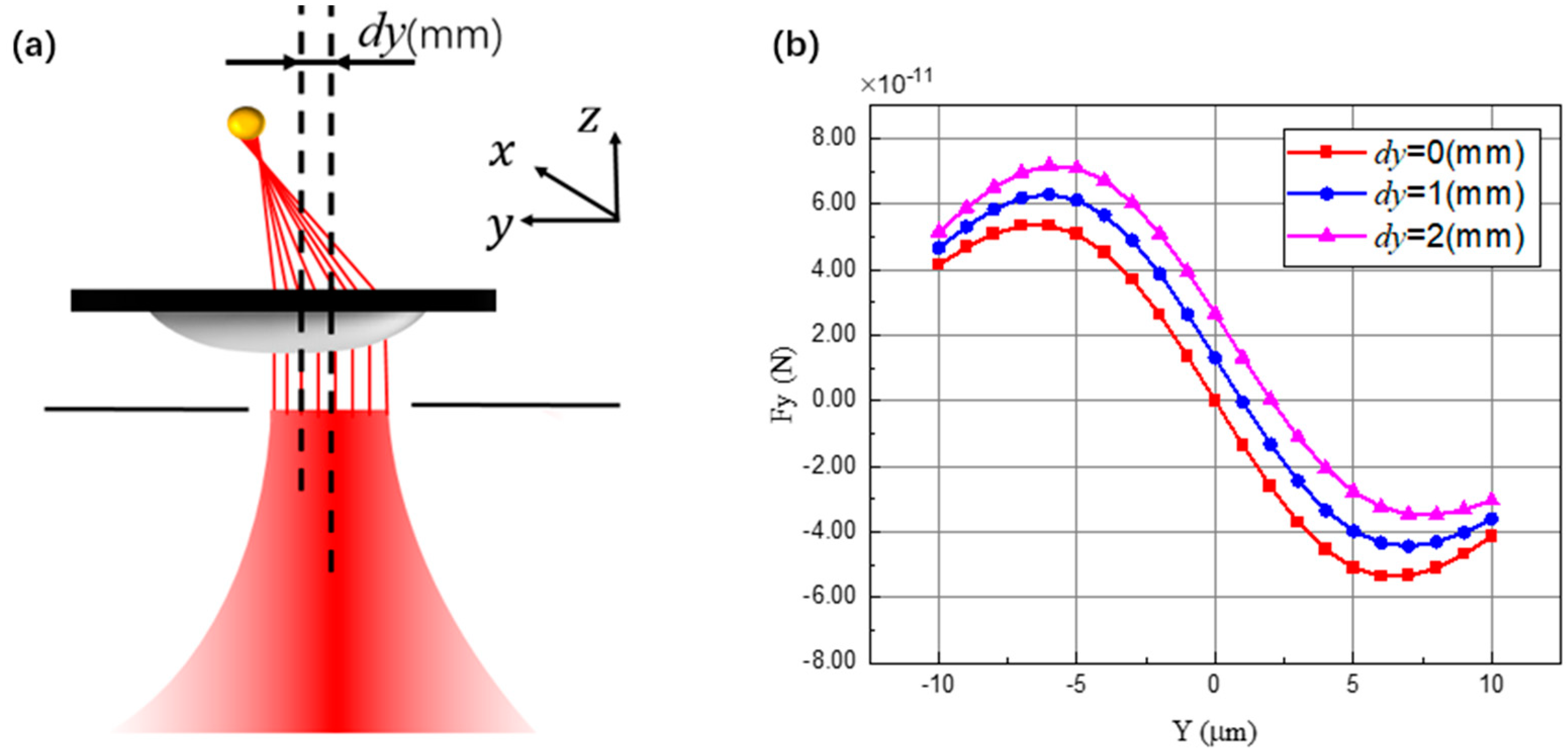
Ideally, beam center of the fundamental-mode Gaussian light should pass through lens center to satisfy the coaxial condition. However, owing to the limited position accuracy of the lens, it is difficult to satisfy the coaxial condition in the experiment. This off-axis misalignments between the lens and Gaussian beam will influence optical force calculation result, changing the trapping position and stiffness of optical trap, as shown in Figure 5a.
Figure 5a depicts the light propagating trajectory in off-axis model. Since the lens deviates from the optical axis, optical beam is deflected after passing through the lens. As a result, the center of the beam focused by the lens is shifted. Hence, we reset the origin of the coordinate at the center of the offset beam. Since the off-axis of the lens introduces additional deflection to the light, the optical trapping force received by the microsphere changes accordingly. Figure 5b illustrates the change in the restoring force curve when the microsphere moves along the y-axis, which is parallel to the off-axis direction of the lens for various values of dy.
When the lens is placed ideally, Figure 5b shows that the restoring force curve has perfect symmetry and the force balance point is also located at the center of the beam, as shown in the red line. When the lens moves up along the y-axis, the restoring force curve gradually loses symmetry, and the radial equilibrium position of the microspheres also shifts. When the lens moves in the positive direction of the y-axis, the balance point also moves in the positive direction relative to the center of the beam, as shown with blue and magenta lines. The reason for the deviation of the equilibrium point is the deflection of the chief ray. The scattering force generated by the chief ray should ideally be along the z-axis direction. However, when the lens is misaligned, a component of the scattering force runs along the y-axis. Hence, in the off-axis case, the microsphere will be affected by the transverse force at the center of the beam, leading to a shift in the balance point. Next, we proceed to the change in the stiffness of the optical trap under the influence of the lens off-axis.
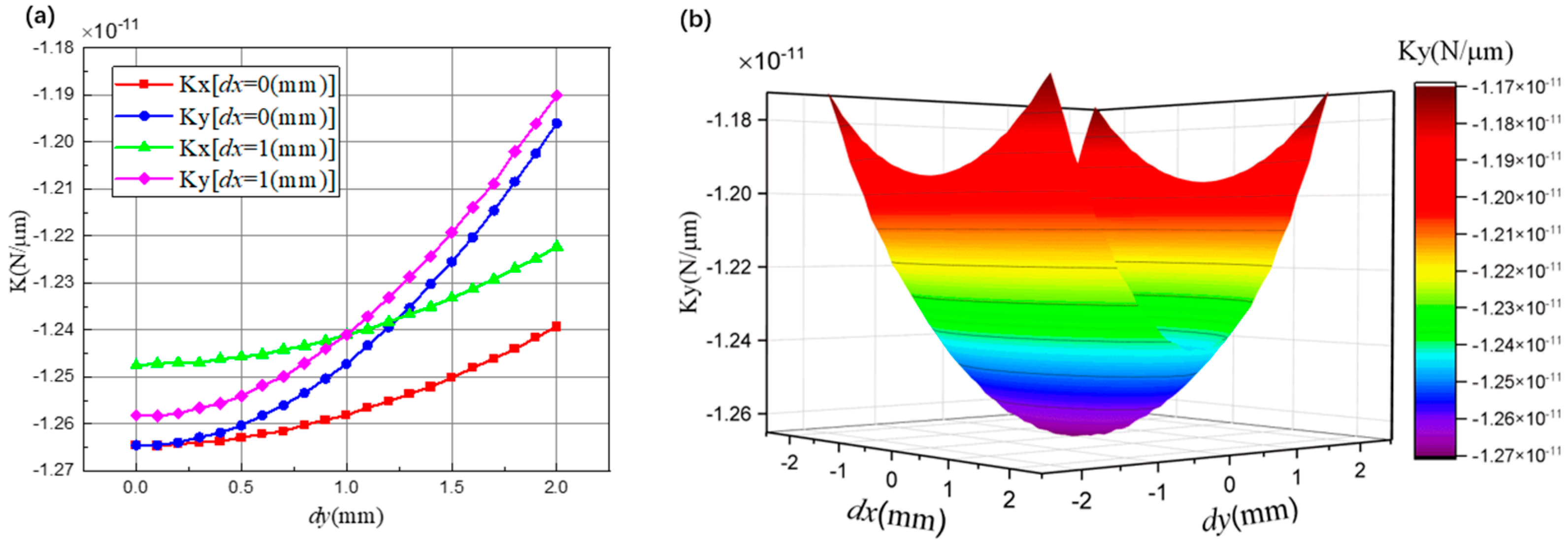
Since the experimental system will not only have the off-axis error of the lens in a certain direction, we have added the lens offset in the x-axis direction in Figure 6, which is represented by the parameter dx. In addition, with the shift of the lens, the symmetry of the optical tweezer system is broken, so the stiffness along the y-axis direction (Ky) and that along the x-axis direction (Kx) are no longer the same. Figure 6a illustrates the changing trend of Kx and Ky as the lens shifts continuously along the y-axis. The off-axis of the lens will decrease the absolute value of stiffness. The change in Ky is more obvious than that in Kx. As the degree of lens shift increases, the gap between Kx and Ky increases, as shown in Figure 6a. However, when dy is 2 mm, the difference between Kx and Ky only reaches 4%. Hence, the off-axis error of the lens will not severely damage the axial symmetry of the optical trap stiffness.
Figure 6a also shows the effect of the continuous off-axis in the y-direction on the stiffness of the optical trap when the lens has a fixed offset in the x-axis direction. The trend of changes in Kx and Ky is similar to the previous one, and when dx = dy = 1 mm, Kx = Ky, which shows that when the displacement error of the lens is symmetrical, the optical trap stiffness will also be symmetrical. Figure 6b illustrates the change in the stiffness of the optical trap when the lens is shifted in a 2D plane. When the lens is coaxial with the incident beam, the absolute value of the stiffness of the optical trap is the largest. The farther the lens center is from the optical axis, the smaller the absolute value of the optical trap stiffness. In Figure 6b, dx = 2 mm and dy = 2 mm are the maximum off-axis lens conditions, and the absolute value of the optical trap stiffness is reduced by 7.8% compared to the ideal placement.
3.4. Lens Tilting Simulation
The tilt of the lens is another common misalignment in the experimental system. As previously stated, we will now investigate the influence of the tilt error on the restoring force curve and the stiffness of the optical trap.
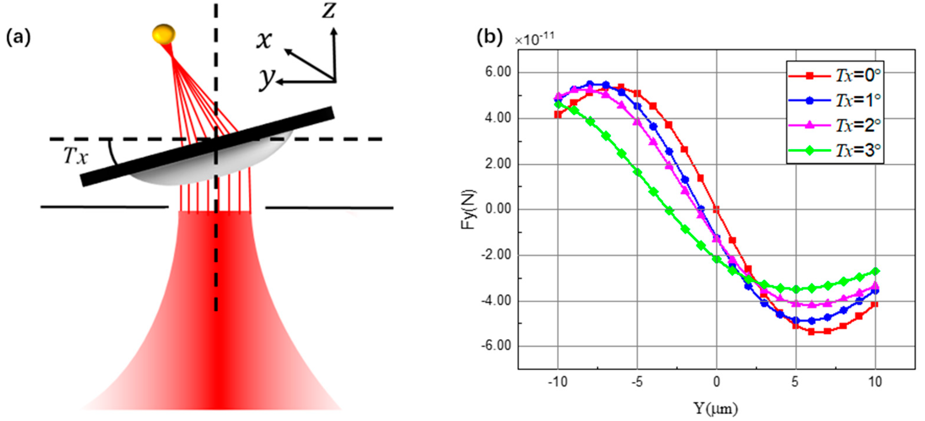
Ideally, lens should be orthogonal to the optical axis. However, owing to the limited placement accuracy of experiment, the placement of the lens may have a small inclination. The tilting angle of the lens around the x-axis is represented by the parameter Tx in Figure 7a. The tilt of the lens will deflect the chief ray, so the center of the focused beam is no longer on the optical axis. Therefore, we reset the origin of the coordinate system to the offset beam center. In other words, the point of Y = 0, X = 0 represents the position of the chief ray. In addition, we stipulate that when the lens is tilted, the vertex of the convex surface of the lens is always aligned with the center of the beam.
Figure 7b demonstrates the change in the restoring force curve of the optical trap caused by different tilt angles. The restoring force curve becomes increasingly asymmetric with an increase in the tilt angle. Furthermore, the clockwise tilt around the x-axis makes the radial equilibrium point move in the negative direction of the y-axis. According to our simulation, the clockwise rotation of the lens enhances the scattering force of each ray along the negative direction of the y-axis. Owing to the asymmetrical curve and the shift of the balance point, the linear interval of the restoring force curve obtained by the movement of the microsphere along the y-axis is also changed. This means that the tilt error of the lens makes certain areas in the optical trap force curve has a change in the stiffness of the optical trap.
We consider one further step to deal with the changing trend of stiffness under the influence of lens tilting. To make the simulation more realistic, we have increased the tilt angle around the y-axis direction (Ty) in Figure 8. As shown in Figure 8a, the tilt error of the lens breaks the symmetry of the optical trap stiffness in the x-axis direction (Kx) and the y-axis direction (Ky). When Ty is fixed and Tx increases, the absolute value of Kx will increase, but that of Ky will decrease; when Ty = 0° and Tx = 3°, the value of Kx is approximately 2.7 times that of Ky. Therefore, in the experiment, the tilt error of the lens may cause more severe influence to the stiffness symmetry of the optical trap system than the off-axis error.
Figure 8a also illustrates the influence of continuously changing Tx with fixed 1° of Ty on the stiffness. The changing trend of Kx and Ky is the same as that of Ty = 0°. Besides, when Tx = Ty = 1°, Kx = Ky, showing once again that symmetrical displacement will lead to symmetrical stiffness. Figure 8b indicates the change of the stiffness of the optical trap when the lens is continuously tilted around the x- and y-axes at the same time. When the lens is tilted around the y-axis, the absolute value of Ky will increase and that of Ky at Ty = 3° is approximately 23% higher than that at Ty = 0°. When the lens is tilted around the x-axis, the absolute value of Ky will decrease and that of Ky at Ty = 0° is approximately twice that at Ty = 3°. Thus, the tilt error of the lens has a greater impact on the stiffness of the optical trap in a direction orthogonal to the tilt axis.
3.5. Variation of Stiffness with Coupled Misalignments
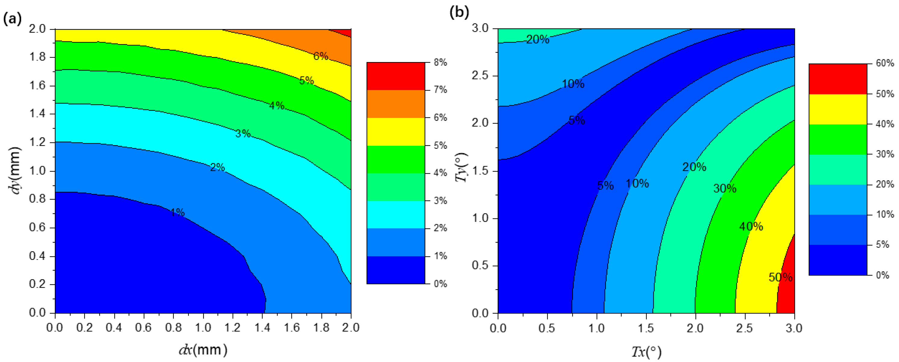
In Figure 9, we plot the percentage variation in Ky with different misalignment parameters. The difference introduced by the off-axis is shown in Figure 9a, and that introduced by the tilt is shown in Figure 9b.
Different colors represent the degree of change in the absolute value of Ky compared with the situation of perfect placement. The results indicate that the stiffness is mainly affected by the tilt error. The off-axis error basically does not cause a difference of more than 6%. However, since Tx and Ty have opposite effects on Ky, the area shown in Figure 9b is more complicated. Basically, the tilt error within 1° will not cause a difference of more than 10%.
From the aforementioned calculations, both the off-axis and tilt errors influence stiffness. Hence, we proceeded with analyzing the simultaneous existence of the tilt and off-axis errors to obtain more realistic simulations.
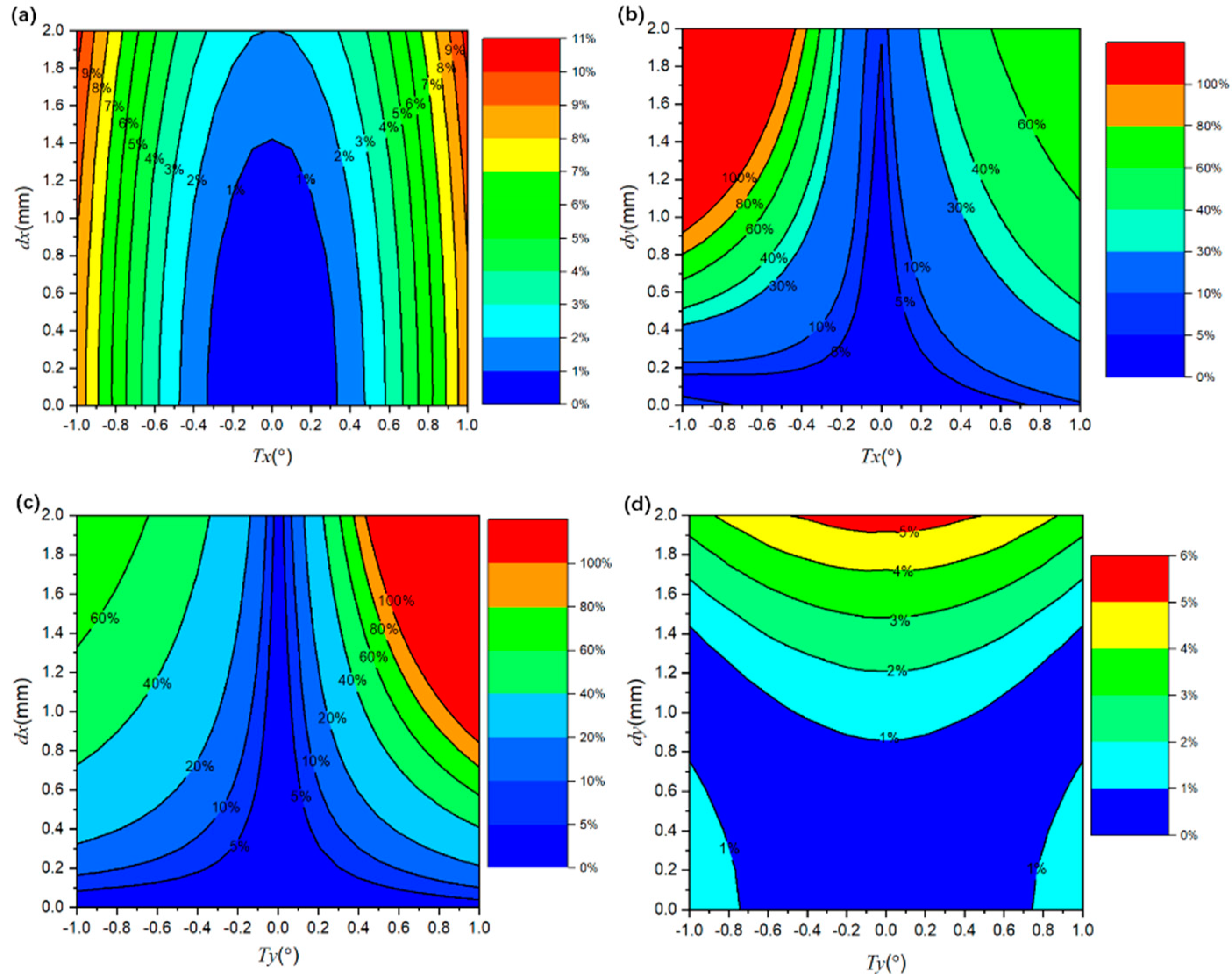
In Figure 10, we plot the percentage variation in Ky with various error combinations. The results indicate that the off-axis and tilt of lens will affect each other significantly. Figure 10a,d, respectively, show that the error combination of Tx and dx and that of Ty and dy have a relatively small impact on stiffness in the y-axis. However, Figure 10b,c indicate that combining errors will cause stiffness to change to a greater extent.
If we define a difference of less than 10% as an acceptable region in experiments, the tilt error of less than 0.3° and the off-axis error of less than 0.4 mm can basically meet the requirements according to Figure 10b,c. Additionally, owing to symmetry, we did not provide the change of Kx under the influence of imperfect placement.
4. Discussion
In conclusion, we have studied the influence of the tilt and off-axis of lens on the optical trapping force in optical tweezers. The typical case of a spherical particle with a size larger than the wavelength was considered. Both of these misalignments will cause the movement of the trapping position in the optical tweezers and break the symmetry of the optical trap stiffness in cross-sections in different ways. The off-axis error will weaken the stiffness in two orthogonal directions at the same time, but the degree of weakening in different directions is different. The tilt error will increase the stiffness in the direction parallel to the tilt axis and weaken the stiffness in the direction orthogonal to it. Under a 2-mm off-axis condition, the stiffness difference between the two orthogonal directions is 4%. Under the condition of tilting 3°, the stiffness in the tilting axis direction is 2.7 times the stiffness of the orthogonal direction. Therefore, lens tilting has a greater impact on the optical trapping force than has the off-axis error. In addition, the influence of the off-axis and tilt errors on stiffness has its characteristics. Off-axis of lens will weaken stiffness, and lens tilt will have different effects on stiffness in different directions.
Since the simultaneous off-axis and tilt simulation may introduce non-negligible deviations in the experimental results, it is necessary to discuss methods for eliminating these two systematic misalignments. According to the simulation results, different misalignments corresponds to different stiffness changes and trapping position, which can provide guidance in the experiment to reduce misalignments. Hence, our study will be useful in understanding the phenomenon of the asymmetry of optical trap stiffness in the experiment, and it may also guide the correction of imperfect installation of the lens according to the changing trend of stiffness.
Author Contributions
Conceptualization, W.L.; writing-original draft preparation, H.Z., W.L.; review, N.L., H.H. All authors have read and agreed to the published version of the manuscript.
Funding
Natural National Science Foundation of China (No. 11304282, 61601405), Joint Fund of Ministry of Education (No.6141A02011604), Major Scientific Research Project of Zhejiang Lab (No.2019MB0AD01) and National Program for Special Support of Top-Notch Young Professionals, Fundamental Research Funds for the Central Universities (No.2016XZZX004-01, No.2018XZZX001-08).
Institutional Review Board Statement
Not applicable.
Informed Consent Statement
Not applicable.
Data Availability Statement
The data that support the findings of this study and available from the corresponding author upon reasonable request.
Acknowledgments
The authors wish to thank the anonymous reviewers for their valuable suggestions.
Conflicts of Interest
The authors declare no conflict of interest.
References
- Ashkin, A. Acceleration and trapping of particles by radiation pressure. Phys. Rev. Lett. 1970, 24, 156. [Google Scholar] [CrossRef] [Green Version]
- Ashkin, A.; Dziedzic, J.M. Optical trapping and manipulation of viruses and bacteria. Science 1987, 235, 1517–1520. [Google Scholar] [CrossRef]
- Ashkin, A.; Dziedzic, J.M.; Yamane, T. Optical trapping and manipulation of single cells using infrared laser beams. Nature 1987, 330, 769–771. [Google Scholar] [CrossRef]
- Volpe, G.; Singh, G.P.; Petrov, D. Dynamics of a growing cell in an optical trap. Appl. Phys. Lett. 2006, 88, 231106. [Google Scholar] [CrossRef] [Green Version]
- Zhang, Y.; Min, C.; Dou, X.; Wang, X.; Urbach, H.P.; Somekh, M.G.; Yuan, X. Plasmonic tweezers: For nanoscale optical trapping and beyond. Light Sci. Appl. 2021, 10, 1–41. [Google Scholar] [CrossRef]
- Blakemore, C.P.; Rider, A.D.; Roy, S.; Wang, Q.; Kawasaki, A.; Gratta, G. Three-dimensional force-field microscopy with optically levitated microspheres. Phys. Rev. A 2019, 99, 023816. [Google Scholar] [CrossRef] [Green Version]
- Gieseler, J.; Novotny, L.; Quidant, R. Thermal nonlinearities in a nanomechanical oscillator. Nat. Phys. 2013, 9, 806–810. [Google Scholar] [CrossRef] [Green Version]
- Wang, K.; Schonbrun, E.; Steinvurzel, P.; Crozier, K. Trapping and rotating nanoparticles using a plasmonic nano-tweezer with an integrated heat sink. Nat. Commun. 2011, 2, 1–6. [Google Scholar] [CrossRef] [Green Version]
- Chen, Y. Macroscopic quantum mechanics: Theory and experimental concepts of optomechanics. J. Phys. B At. Mol. Opt. Phys. 2013, 46, 104001. [Google Scholar] [CrossRef] [Green Version]
- Geraci, A.A.; Papp, S.B.; Kitching, J. Short-range force detection using optically cooled levitated microspheres. Phys. Rev. Lett. 2010, 105, 101101. [Google Scholar] [CrossRef] [Green Version]
- Rider, A.D.; Moore, D.C.; Blakemore, C.P.; Louis, M.; Lu, M.; Gratta, G. Search for screened interactions associated with dark energy below the 100 μm length scale. Phys. Rev. Lett. 2016, 117, 101101. [Google Scholar] [CrossRef] [Green Version]
- Li, T.; Kheifets, S.; Medellin, D.; Raizen, M.G. Measurement of the instantaneous velocity of a Brownian particle. Science 2010, 328, 1673–1675. [Google Scholar] [CrossRef] [Green Version]
- Moore, D.C.; Rider, A.D.; Gratta, G. Search for millicharged particles using optically levitated microspheres. Phys. Rev. Lett. 2014, 113, 251801. [Google Scholar] [CrossRef] [Green Version]
- Monteiro, F.; Ghosh, S.; Fine, A.G.; Moore, D.C. Optical levitation of 10-ng spheres with nano-g acceleration sensitivity. Phys. Rev. A 2017, 96, 063841. [Google Scholar] [CrossRef] [Green Version]
- Monteiro, F.; Li, W.; Afek, G.; Li, C.-L.; Mossman, M.; Moore, D.C. Force and acceleration sensing with optically levitated nanogram masses at microkelvin temperatures. Phys. Rev. A 2020, 101, 053835. [Google Scholar] [CrossRef]
- Ren, K.F.; Gréhan, G.; Gouesbet, G. Prediction of reverse radiation pressure by generalized Lorenz–Mie theory. Appl. Opt. 1996, 35, 2702–2710. [Google Scholar] [CrossRef] [PubMed]
- Gouesbet, G.; Maheu, B.; Gréhan, G. Light scattering from a sphere arbitrarily located in a Gaussian beam, using a Bromwich formulation. J. Opt. Soc. Am. A 1988, 5, 1427–1443. [Google Scholar] [CrossRef]
- Harada, Y.; Asakura, T. Radiation forces on a dielectric sphere in the Rayleigh scattering regime. Opt. Commun. 1996, 124, 529–541. [Google Scholar] [CrossRef]
- Novotny, L.; Bian, R.X.; Xie, X.S. Theory of nanometric optical tweezers. Phys. Rev. Lett. 1997, 79, 645. [Google Scholar] [CrossRef] [Green Version]
- Zhou, J.H.; Ren, H.L.; Cai, J.; Li, Y.M. Ray-tracing methodology: Application of spatial analytic geometry in the ray-optic model of optical tweezers. Appl. Opt. 2008, 47, 6307–6314. [Google Scholar] [CrossRef]
- Ashkin, A. Forces of a single-beam gradient laser trap on a dielectric sphere in the ray optics regime. Biophys. J. 1992, 61, 569–582. [Google Scholar] [CrossRef] [Green Version]
- Callegari, A.; Mijalkov, M.; Gököz, A.B.; Volpe, G. Computational toolbox for optical tweezers in geometrical optics. J. Opt. Soc. Am. B 2015, 32, B11–B19. [Google Scholar] [CrossRef] [Green Version]
- Kampmann, R.; Sinzinger, S. Optical tweezers affected by monochromatic aberrations. Appl. Opt. 2017, 56, 1317–1326. [Google Scholar] [CrossRef] [Green Version]
- Dutra, R.S.; Viana, N.B.; Maia Neto, P.A.; Nussenzveig, H.M. Absolute calibration of optical tweezers including aberrations. Appl. Phys. Lett. 2012, 100, 131115. [Google Scholar] [CrossRef] [Green Version]
- Zemax, R. Zemax 13 Optical Design Program User’s Manual; Zemax LLC, 2014; Available online: www.zemax.com (accessed on 10 November 2021).
- Zhu, X.; Li, N.; Yang, J.; Chen, X.; Hu, H. Displacement detection decoupling in counter-propagating dual-beams optical tweezers with large-sized particle. Sensors 2020, 20, 4916. [Google Scholar] [CrossRef]
- Kitamura, R.; Pilon, L.; Jonasz, M. Optical constants of silica glass from extreme ultraviolet to far infrared at near room temperature. Appl. Opt. 2007, 46, 8118–8133. [Google Scholar] [CrossRef] [PubMed]
Figure 1.
Schematic diagram of the light path after a single ray is incident on the microsphere.

Figure 2.
Simplified schematic diagram of the calculation model of optical trap force in geometrical optics range where Gaussian beam can be decomposed into a set of optical rays.
Figure 2.
Simplified schematic diagram of the calculation model of optical trap force in geometrical optics range where Gaussian beam can be decomposed into a set of optical rays.

Figure 3.
Comparison of the longitudinal force received by the microspheres at different positions on the z-axis (a) and the transverse restoring force received by the microsphere moving along the x-axis (b) calculated by the two methods under the radiation of incident light with different waist radii.

Figure 4.
Longitudinal force (a) and transverse force (b) exerted on the microsphere as it moves in the x-y plane 100 microns to the right of the focus.
Figure 4.
Longitudinal force (a) and transverse force (b) exerted on the microsphere as it moves in the x-y plane 100 microns to the right of the focus.

Figure 5.
(a) Off-axis model of lens in optical trap system; (b) the restoring force curve corresponding to different off-axis distances of the lens when the microsphere moves along the y-axis.
Figure 5.
(a) Off-axis model of lens in optical trap system; (b) the restoring force curve corresponding to different off-axis distances of the lens when the microsphere moves along the y-axis.

Figure 6.
The influence of the off-axis of the lens on the stiffness of the optical trap. (a) When the offset of the lens in the x-axis direction is fixed and continuously shifted along the y-axis, the stiffness of the optical trap changes in the x-axis direction and the y-axis direction. (b) The changing trend of the y-axis stiffness.

Figure 7.
(a) The tilt model of the lens in the optical trap system. (b) The restoring force curve corresponding to different tilt angles of the lens when the microsphere moves along the y-axis.
Figure 7.
(a) The tilt model of the lens in the optical trap system. (b) The restoring force curve corresponding to different tilt angles of the lens when the microsphere moves along the y-axis.

Figure 8.
The influence of the tilt of the lens on the stiffness of the optical trap. (a) The tilt angle of the lens around the y-axis (Ty) is fixed and the tilt angle around the x-axis (Tx) continuously changes, the changing trend of the Kx and Ky. (b) The lens is tilted around both the x-axis direction and y-axis direction, the changing trend of the Ky.

Figure 9.
Variation of stiffness along y direction as a function of: (a) dx and dy (b) Tx and Ty.

Figure 10.
Stiffness variation along y direction as a function of (a) Tx and dx, (b) Tx and dy, (c) Ty and dx, (d) Ty and dx.
Figure 10.
Stiffness variation along y direction as a function of (a) Tx and dx, (b) Tx and dy, (c) Ty and dx, (d) Ty and dx.

Publisher’s Note: MDPI stays neutral with regard to jurisdictional claims in published maps and institutional affiliations. |
© 2021 by the authors. Licensee MDPI, Basel, Switzerland. This article is an open access article distributed under the terms and conditions of the Creative Commons Attribution (CC BY) license (https://creativecommons.org/licenses/by/4.0/).
Share and Cite
MDPI and ACS Style
Zhang, H.; Li, W.; Li, N.; Hu, H. Numerical Analysis of Optical Trapping Force Affected by Lens Misalignments. Photonics 2021, 8, 548. https://doi.org/10.3390/photonics8120548
AMA Style
Zhang H, Li W, Li N, Hu H. Numerical Analysis of Optical Trapping Force Affected by Lens Misalignments. Photonics. 2021; 8(12):548. https://doi.org/10.3390/photonics8120548
Chicago/Turabian StyleZhang, Hanlin, Wenqiang Li, Nan Li, and Huizhu Hu. 2021. "Numerical Analysis of Optical Trapping Force Affected by Lens Misalignments" Photonics 8, no. 12: 548. https://doi.org/10.3390/photonics8120548
Note that from the first issue of 2016, this journal uses article numbers instead of page numbers. See further details here.