End-to-End Real-Time Demonstration of the Slotted, SDN-Controlled NEPHELE Optical Datacenter Network


 , , and
Abstract
:
1. Introduction
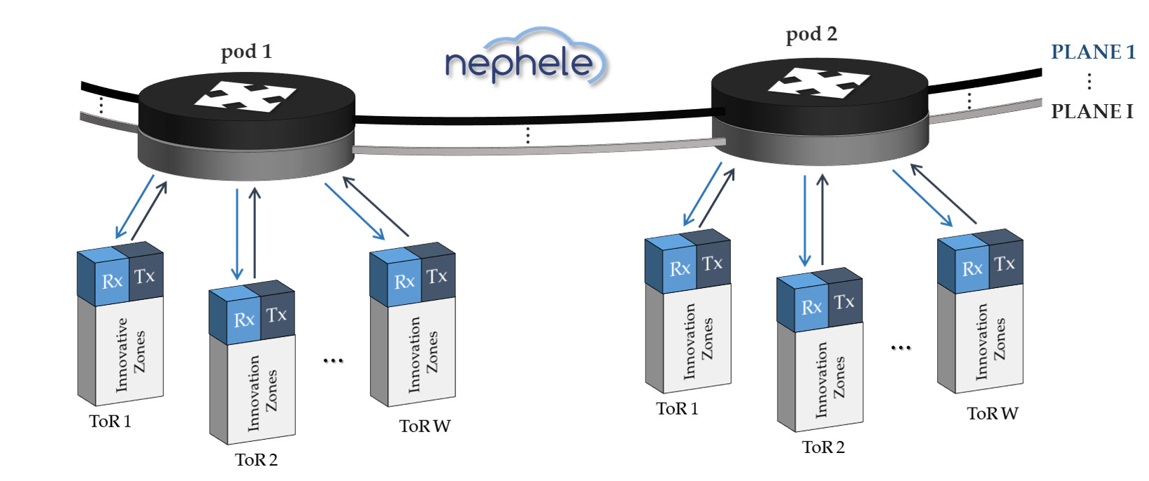
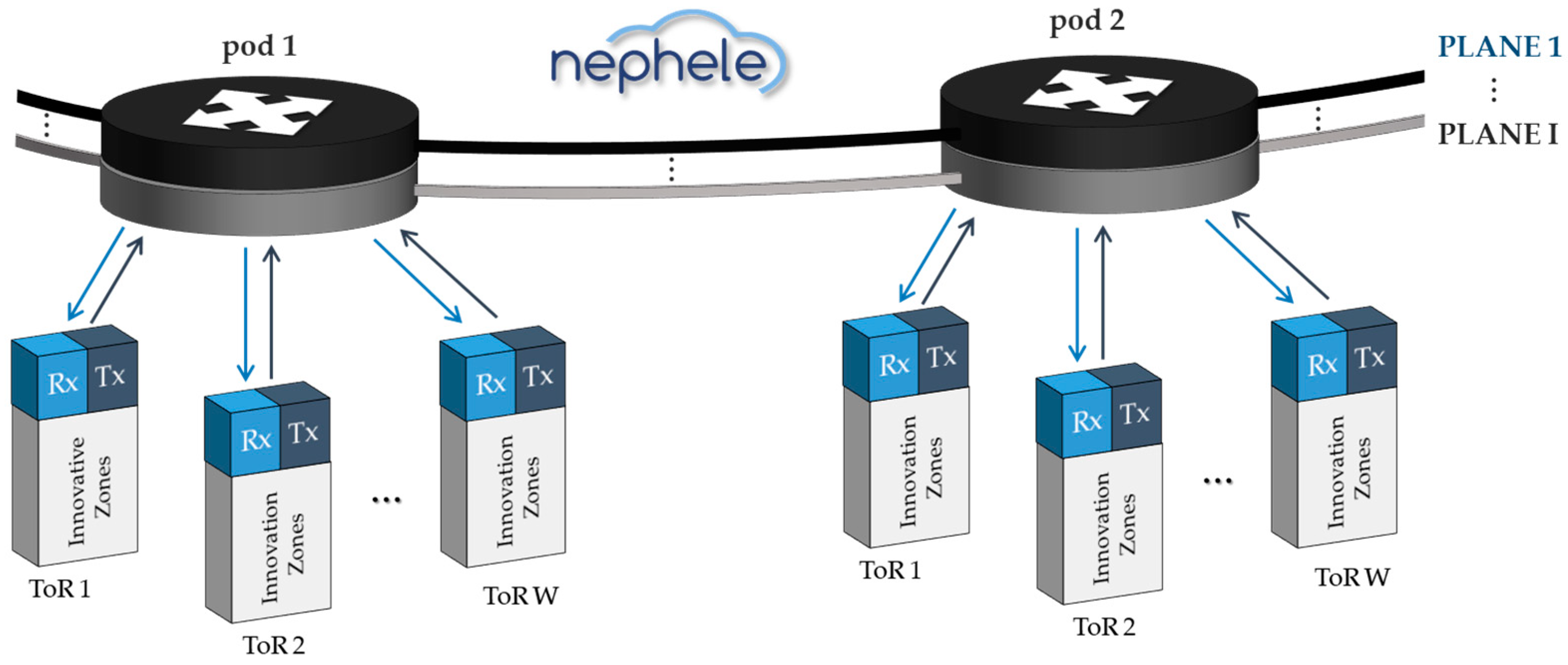
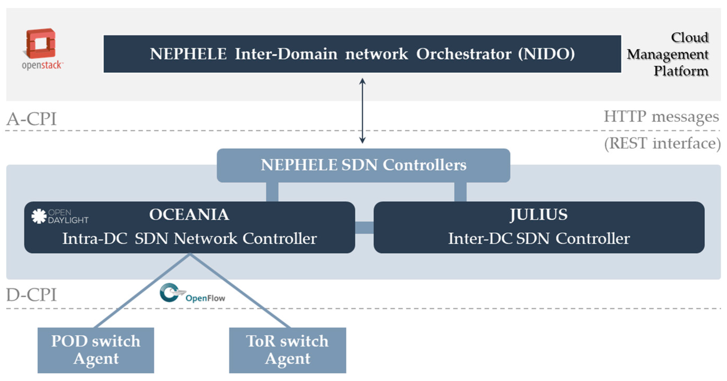
2. The NEPHELE Network Architecture
2.1. Data Plane Overview
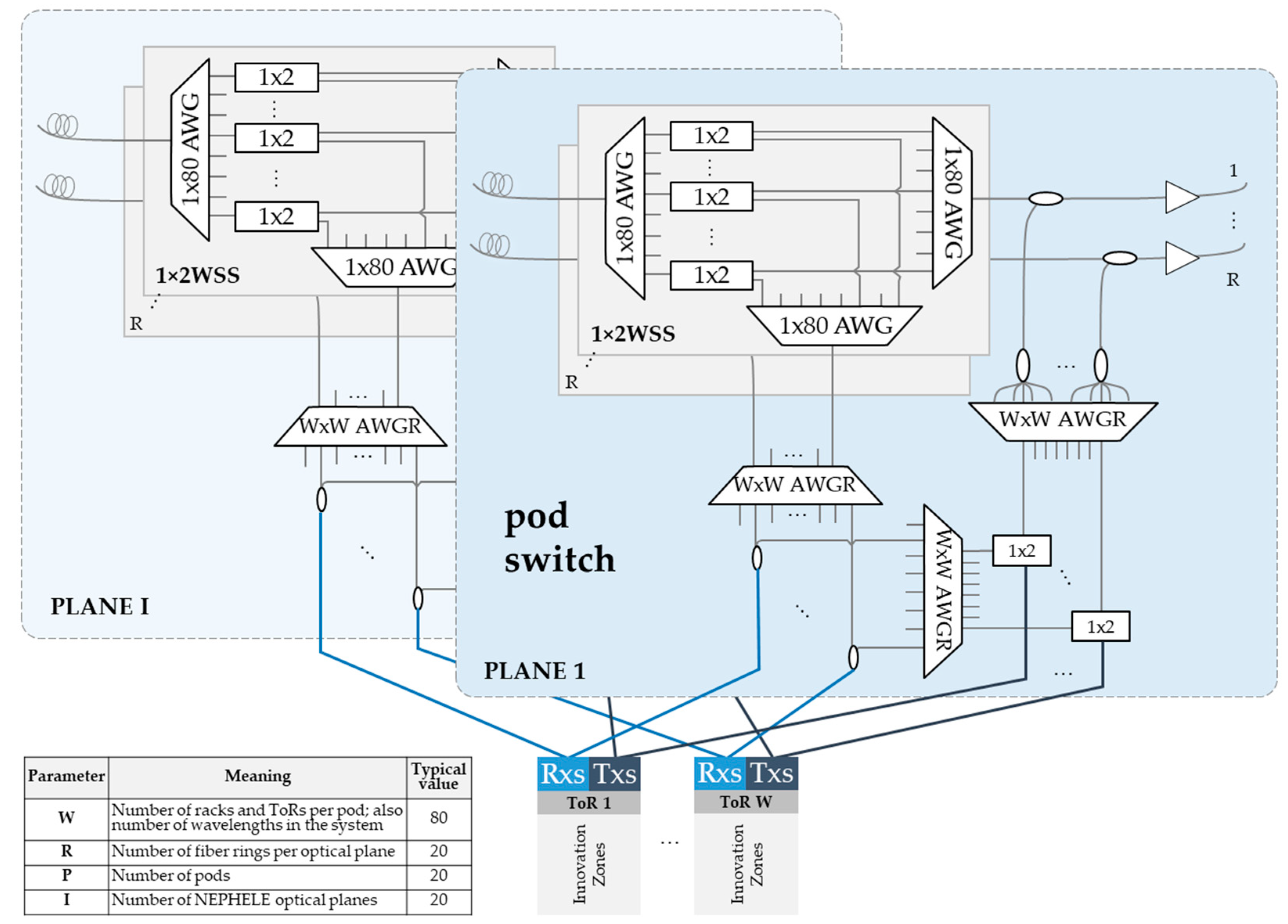
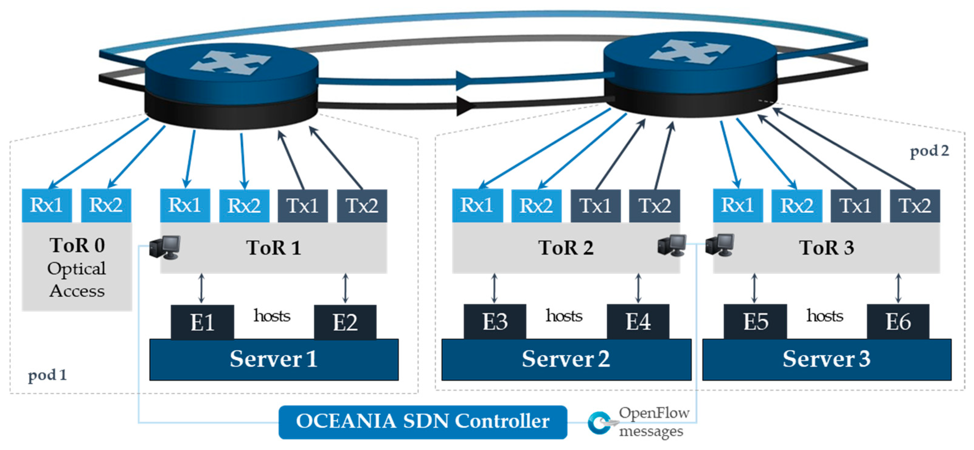
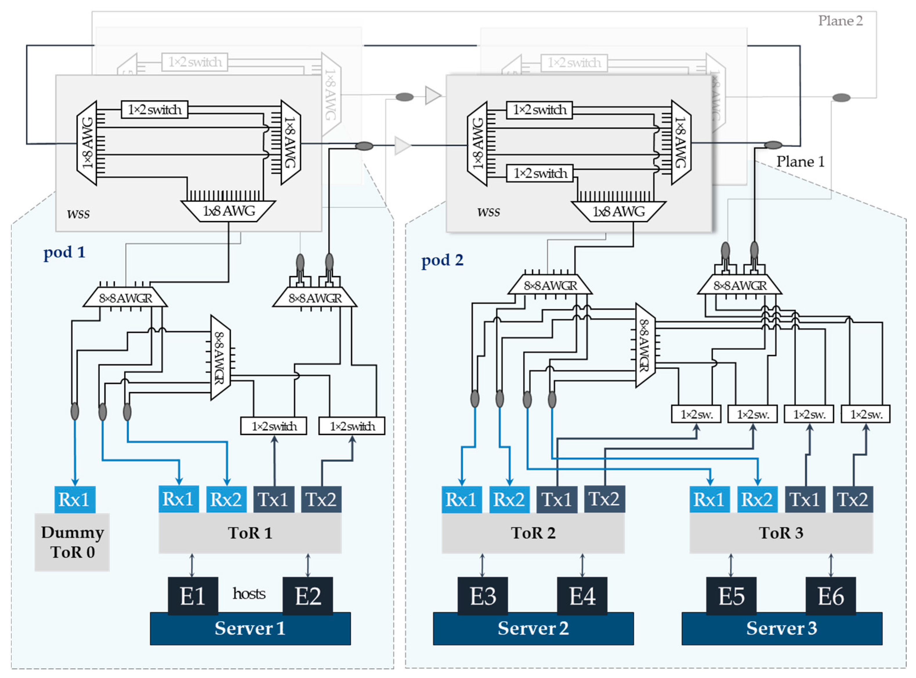
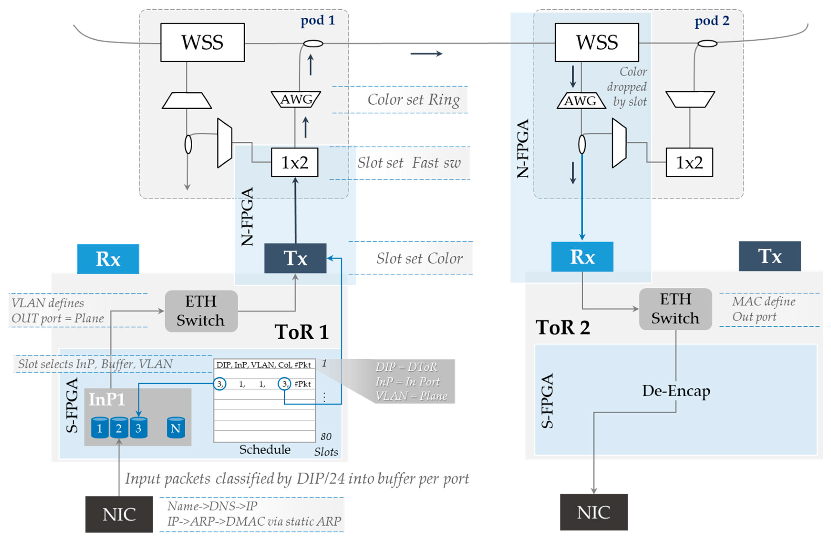
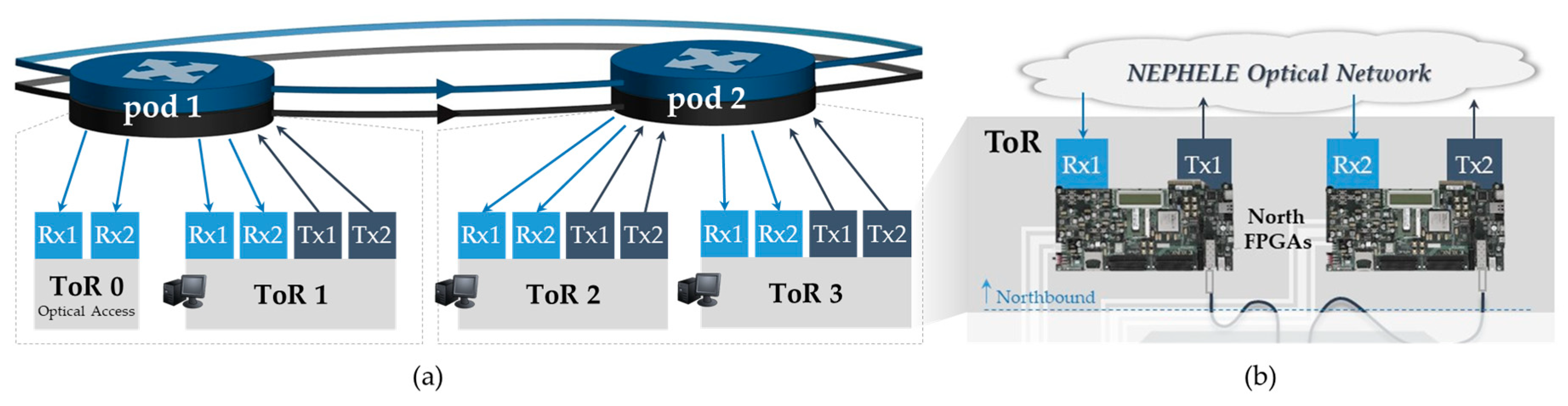
2.1.1. NEPHELE Pod Switch
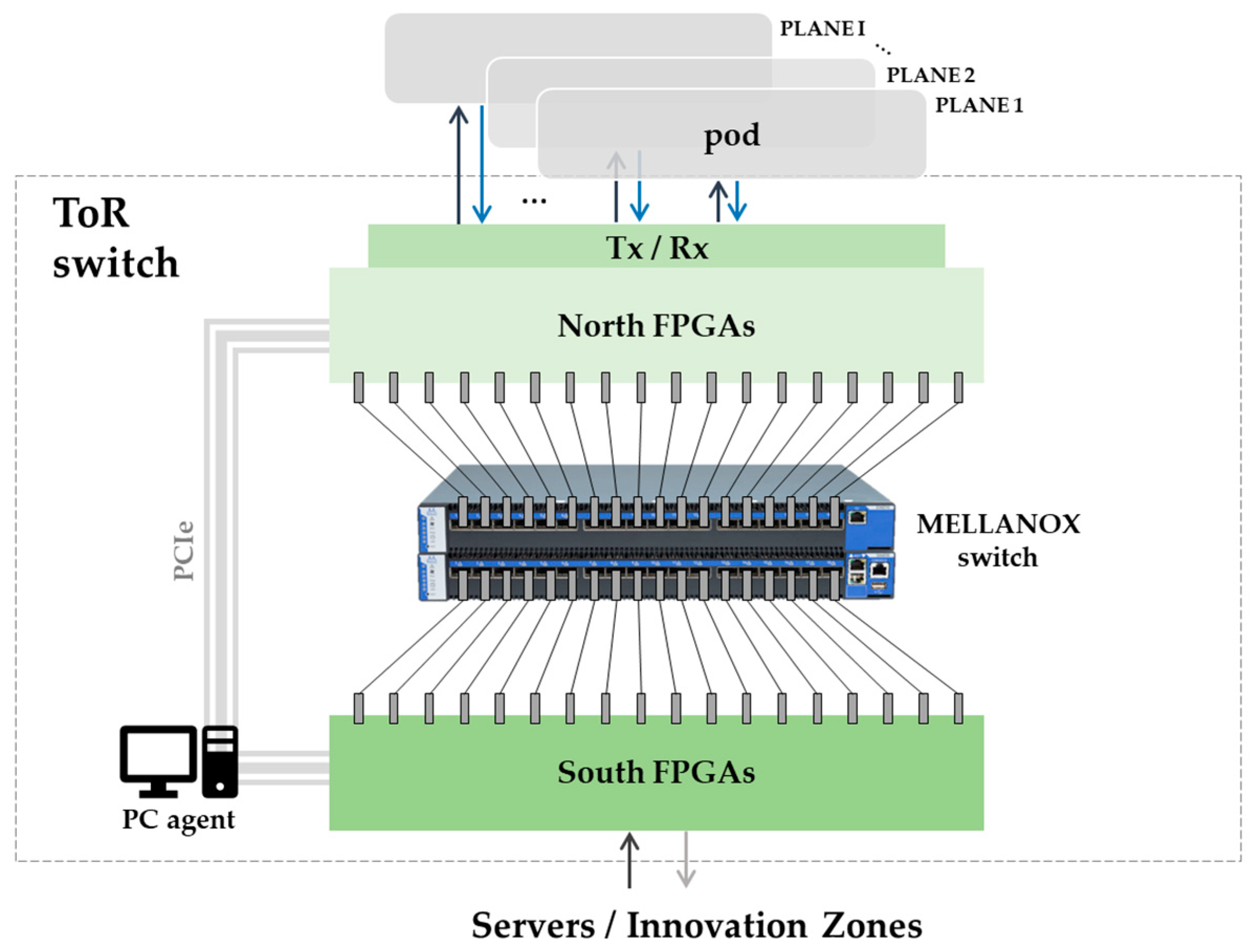
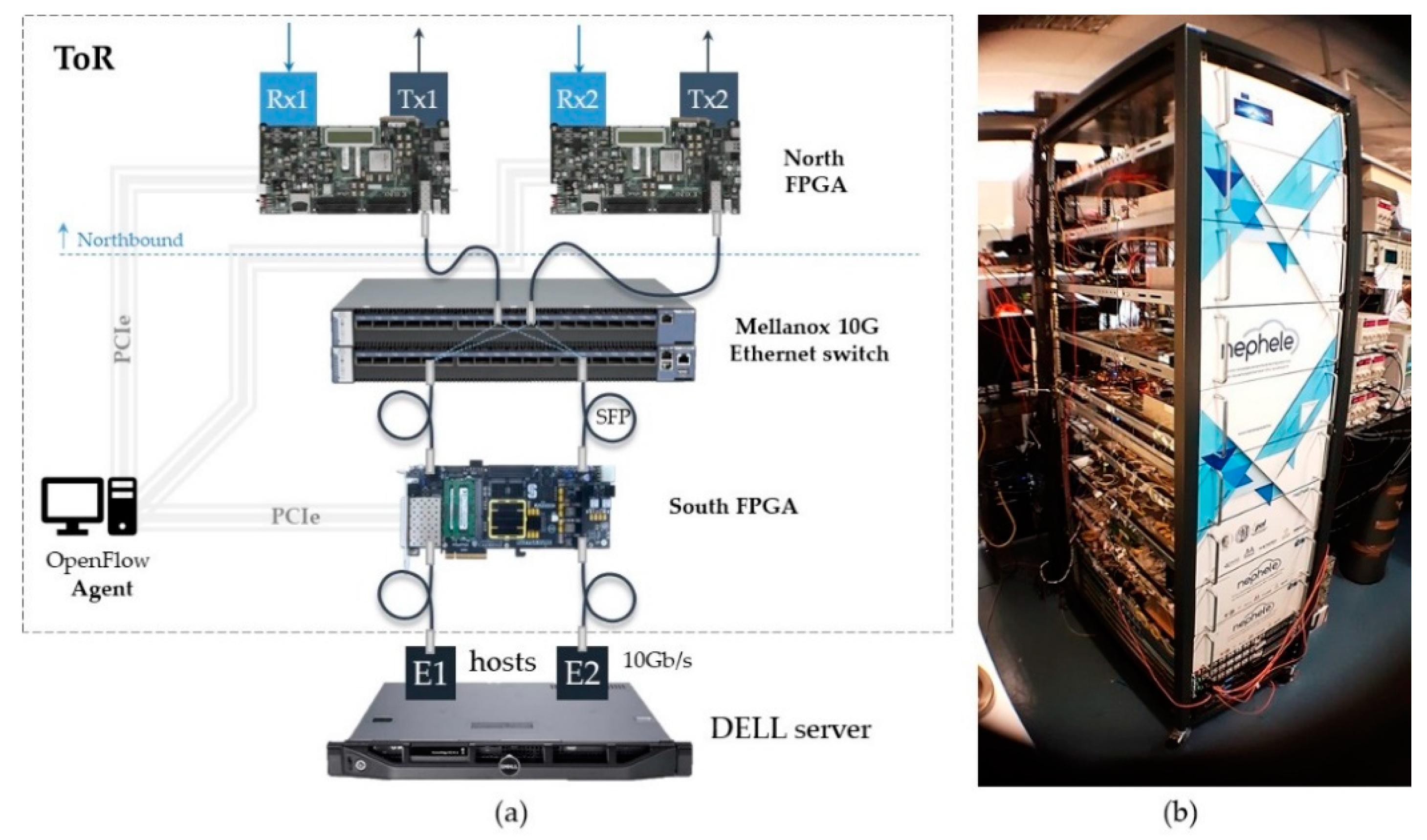
2.1.2. The NEPHELE Top-of-Rack Switch (ToR)
South FPGA (S-FPGA) Extender
Legacy Electrical Switch
North FPGA (N-FPGA) Extender
2.2. Control Plane Overview
3. The NEPHELE Demonstrator Assembly
A “Day” in the Life of a NEPHELE Packet
4. End-to-End Communication Scenarios and Real-Time Demo Results
4.1. Intra-Datacenter Communication
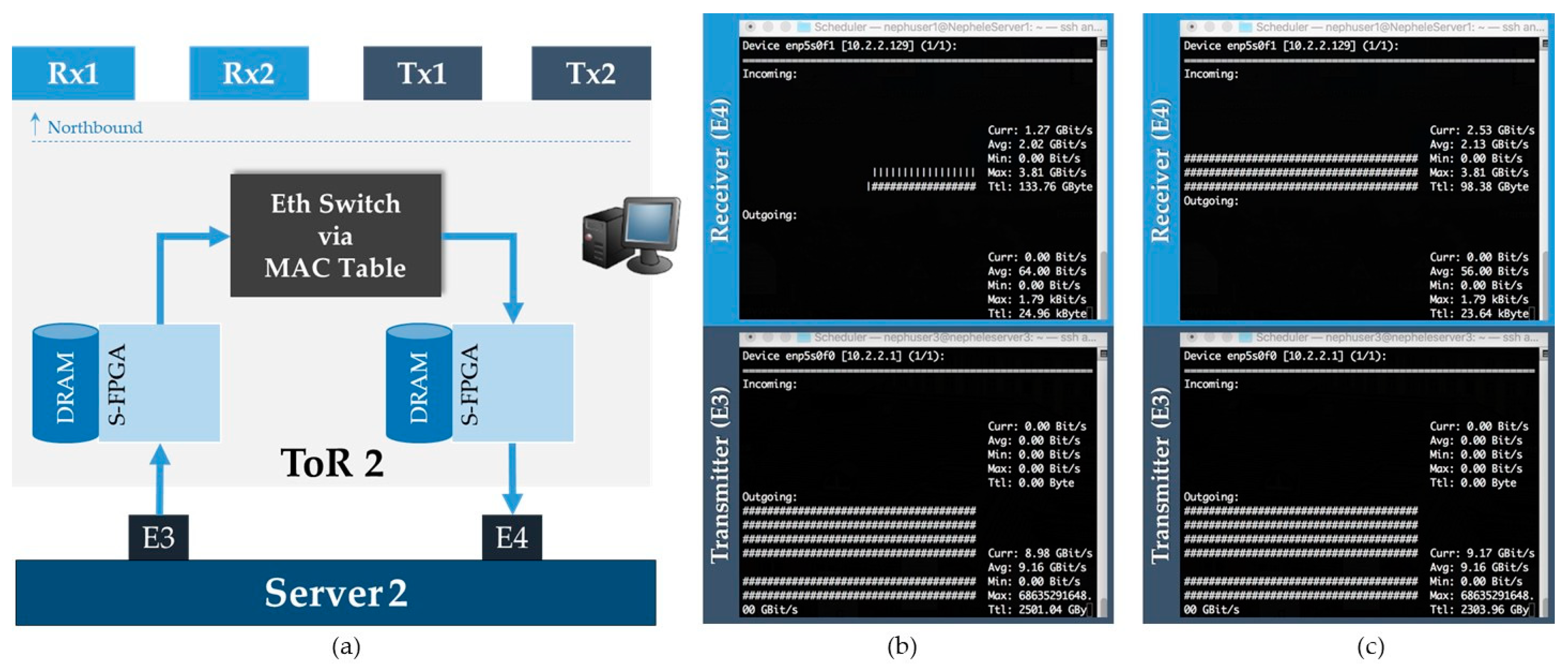
4.1.1. Intra-ToR Scenario
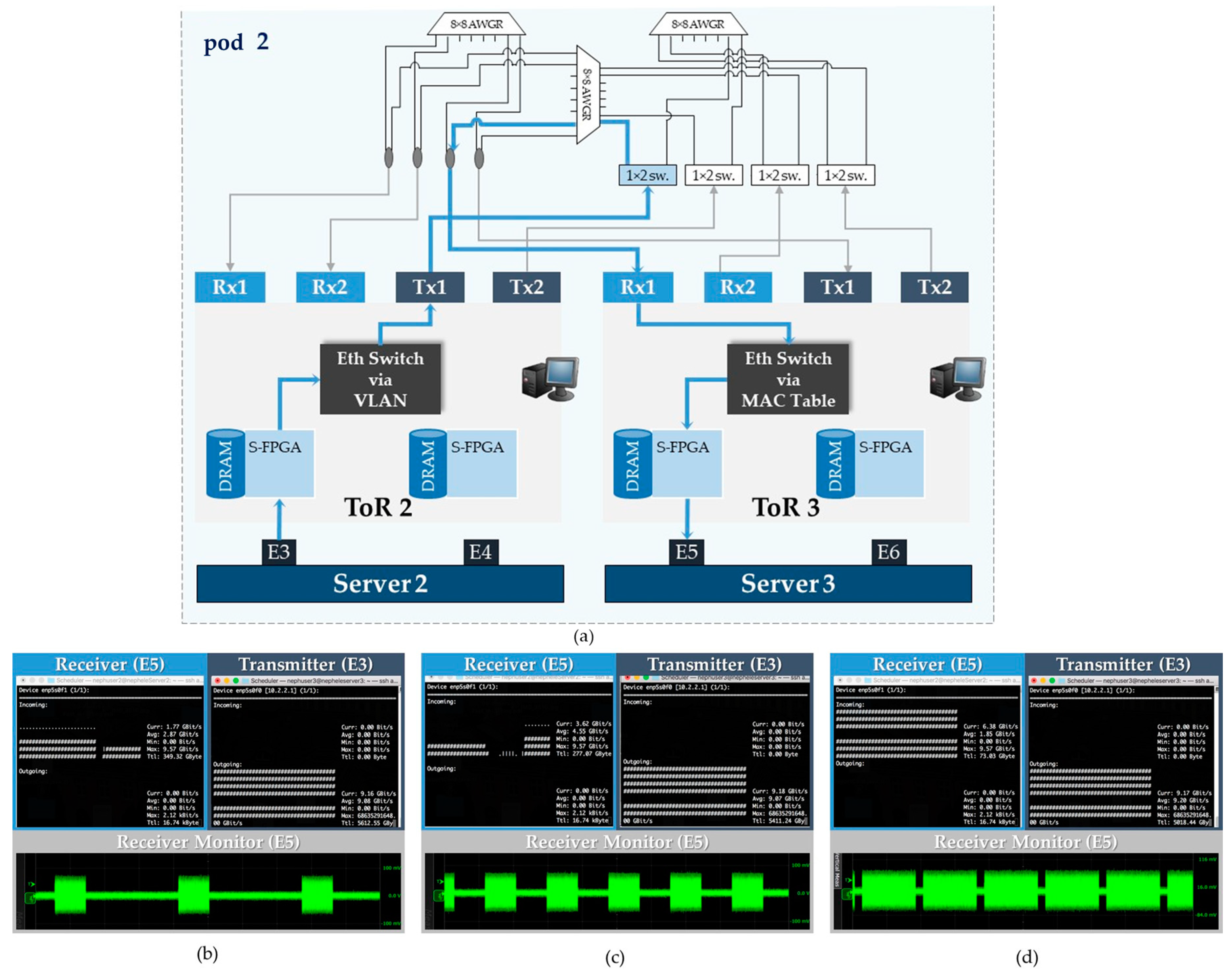
4.1.2. Intra-Pod Scenario
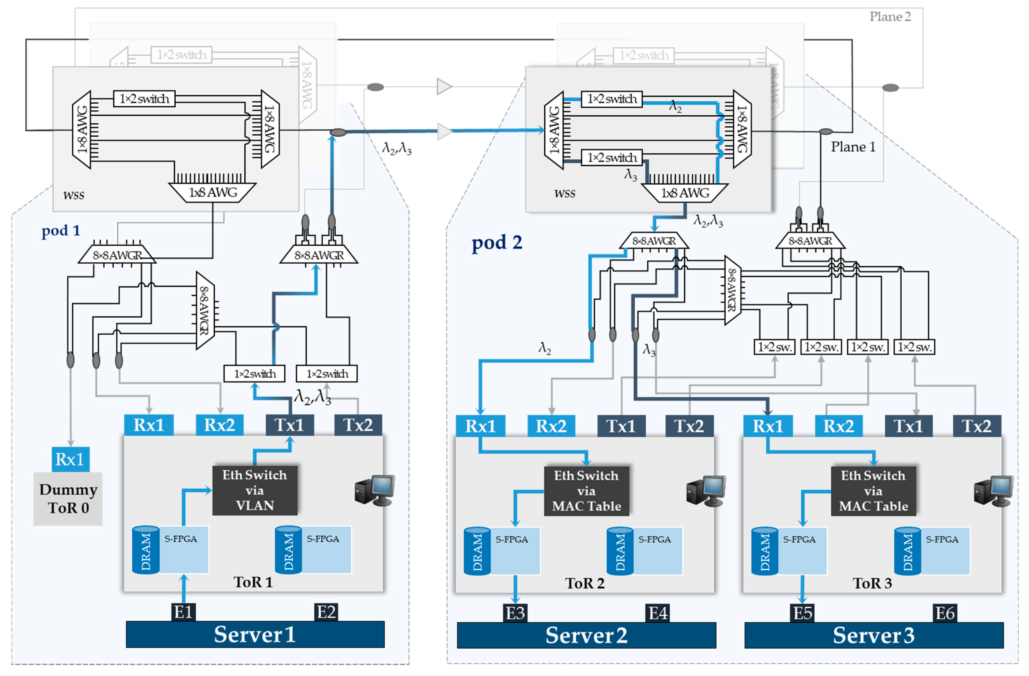
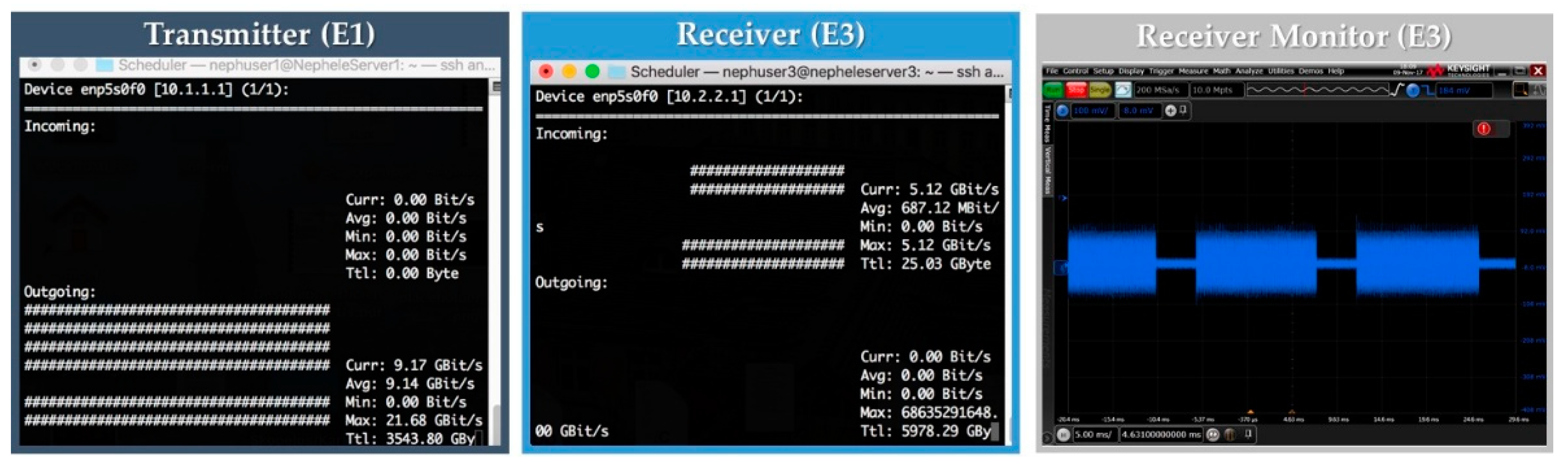
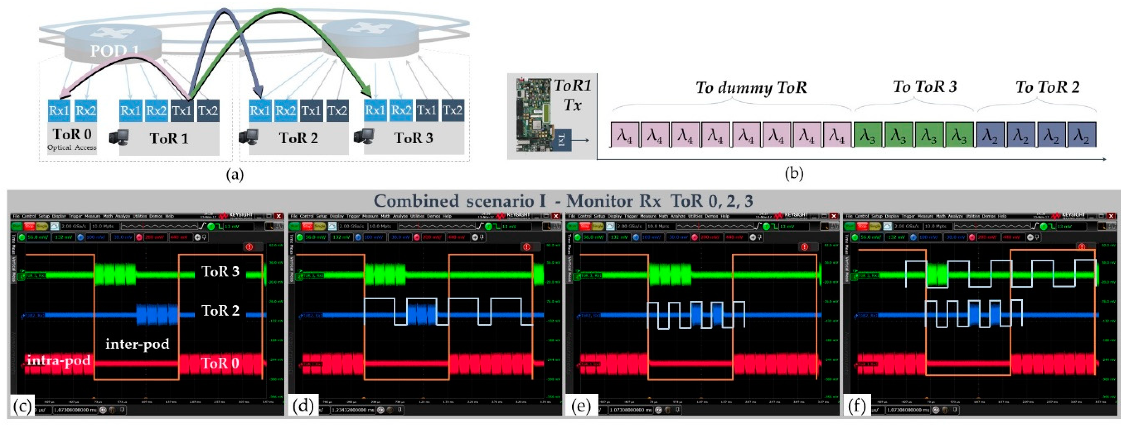
4.1.3. Inter-Pod Scenario I
4.1.4. Inter-Pod Scenario II
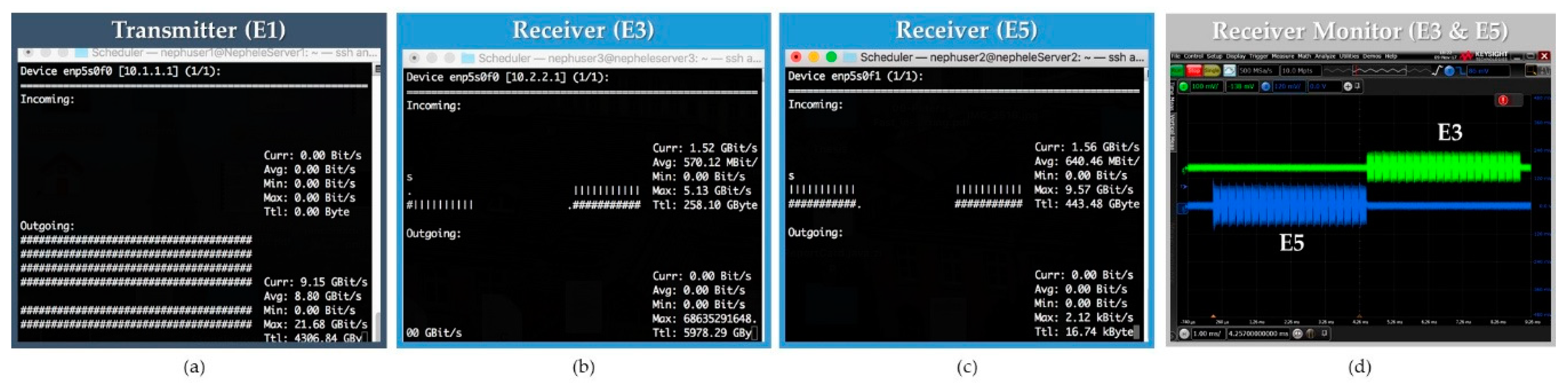
4.1.5. Combined Intra-Pod and Inter-Pod Communication Scenarios
Combined Scenario I
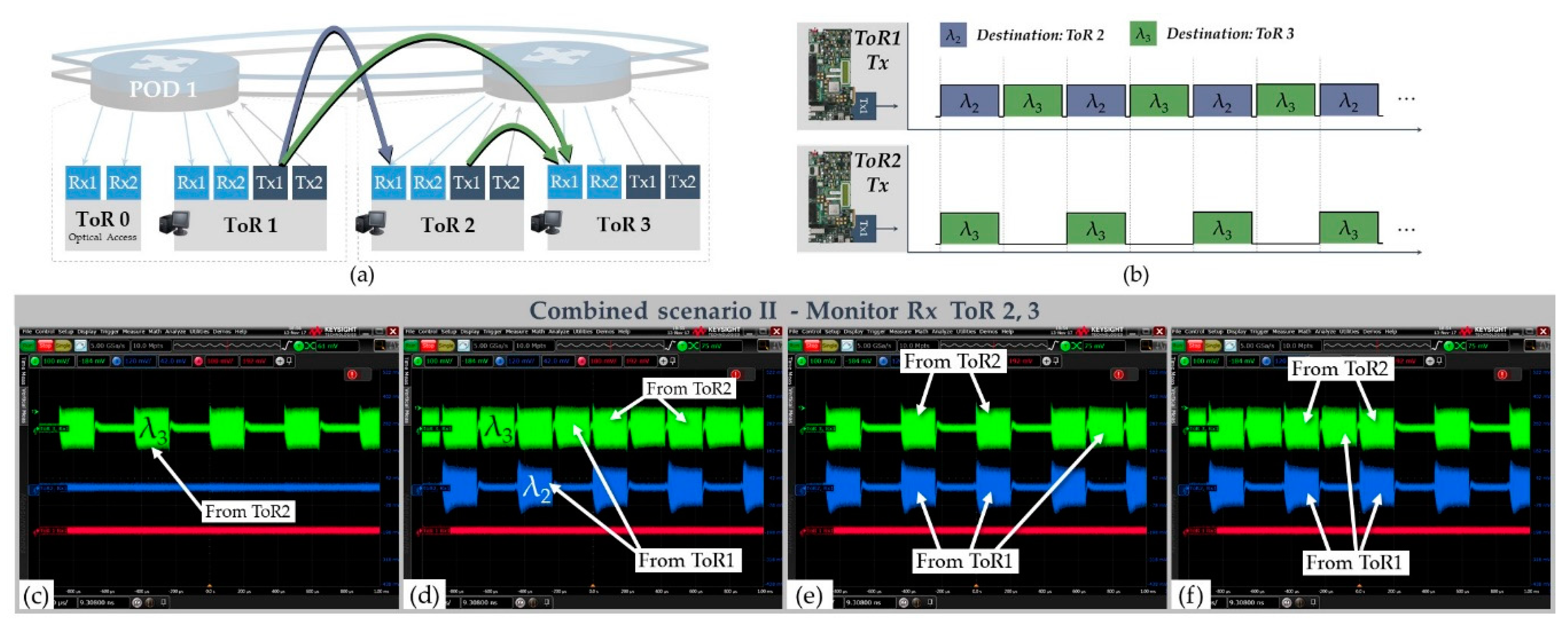
Combined Scenario II
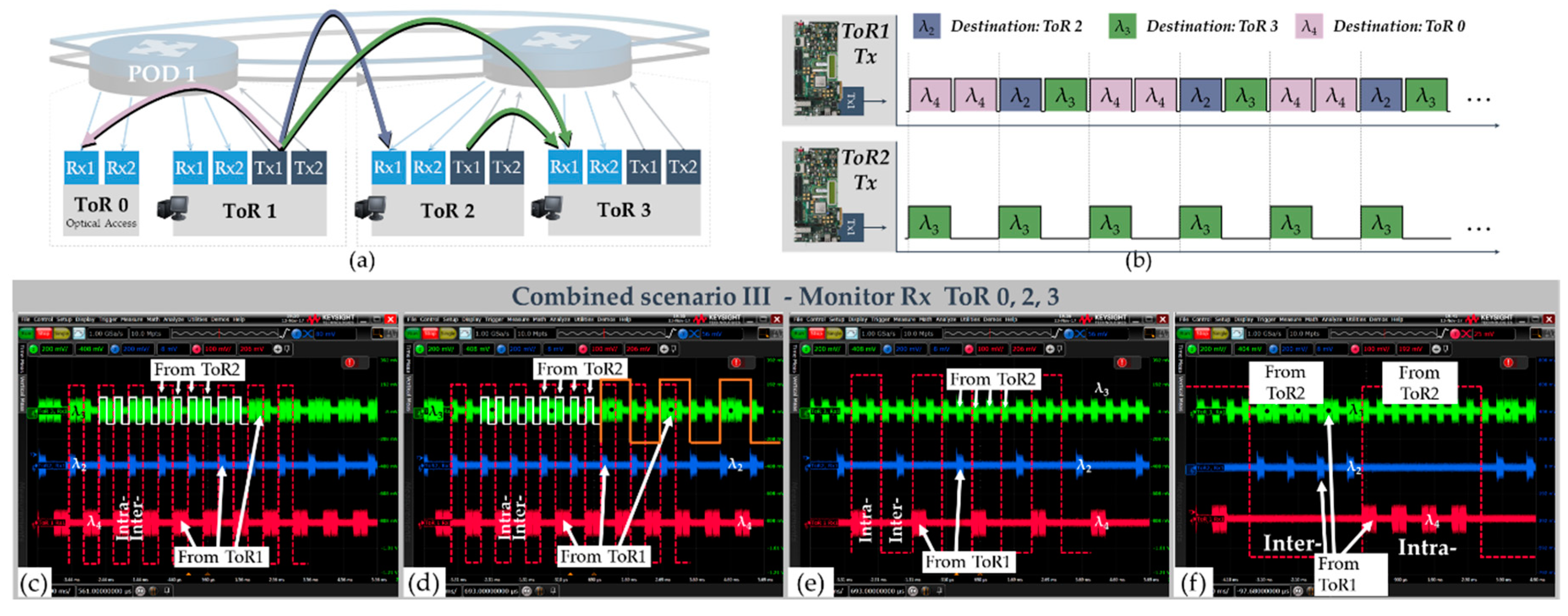
Combined Scenario III
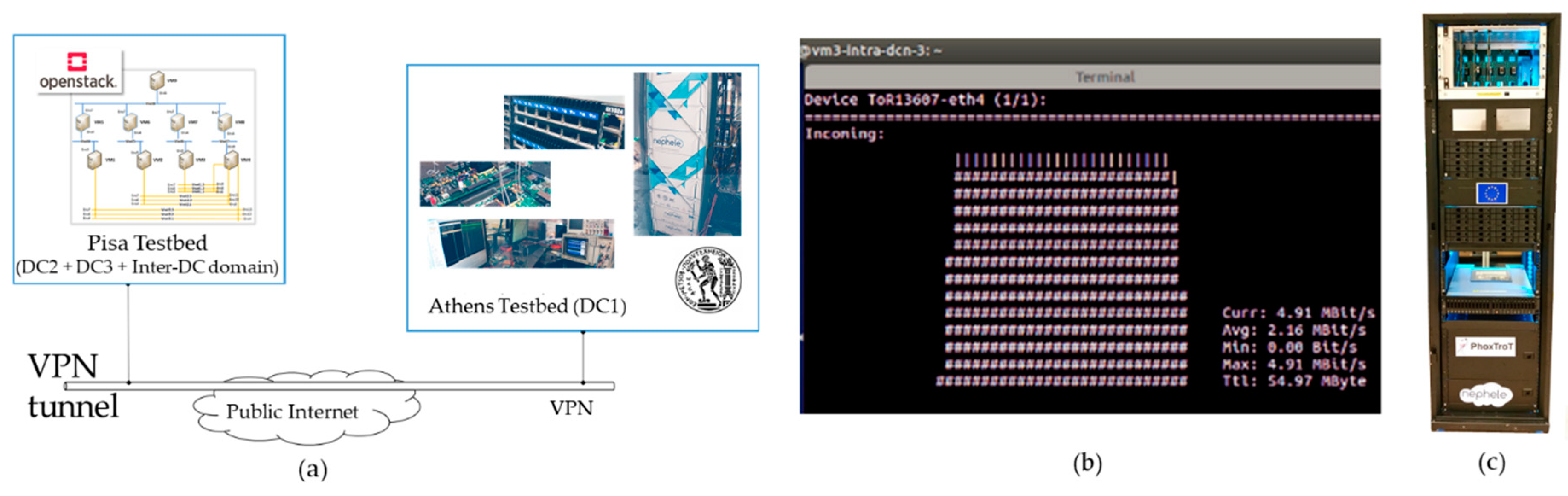
4.2. Inter-Datacenter Communication—Pisa and Athens Testbed Communication
5. Discussion
6. Conclusions
Supplementary Materials
Author Contributions
Funding
Acknowledgments
Conflicts of Interest
References
- Cisco. Cisco Annual Internet Report (2018–2023), White Paper. Available online: https://www.cisco.com/c/en/us/solutions/collateral/executive-perspectives/annual-internet-report/white-paper-c11-741490.html (accessed on 23 June 2020).
- Singh, A.; Ong, J.; Agarwal, A.; Anderson, G.; Armistead, A.; Bannon, R.; Boving, S.; Desai, G.; Felderman, B.; Germano, P.; et al. Jupiter Rising: A Decade of Clos Topologies and Centralized Control in Google’s Datacenter Network. ACM SIGCOMM Comput. Commun. Rev. 2015, 45, 183–197. [Google Scholar] [CrossRef] [Green Version]
- DellEMC. Data Center Networking—Quick Reference Guide. November 2019. Available online: https://www.dellemc.com/resources/en-us/asset/quick-reference-guides/products/networking/Dell_EMC_Networking_-_QRG_-_Data_Center.pdf?fbclid=IwAR2l6ueMbyuXNgCjGoNJ38hlfa_5tRIRtUeRrMmiAa8IIC55PzAsLqvp93k (accessed on 23 June 2020).
- OIF to Present “Cu (see you) Beyond 112 Gbps” Webinar to Debate Requirements for Next Generation Electrical Interconnects, Including Networking Trends and Cloud Scale Applications. Available online: https://www.businesswire.com/news/home/20200601005611/en/OIF-Present-%E2%80%9CCu-112-Gbps%E2%80%9D-Webinar-Debate (accessed on 23 June 2020).
- Mellette, W.M. A Practical Approach to Optical Switching in Data Centers. In Proceedings of the 2019 Optical Fiber Communications Conference and Exhibition (OFC), San Diego, CA, USA, 3 March 2019; pp. 1–3. [Google Scholar]
- Zang, D.; Chen, M.; Sun, N.; Proietti, R.; Yoo, S.J.; Cao, Z. OpticV: An energy-efficient datacenter network architecture by MEMS-based all-optical bypassing. In Proceedings of the 2016 IEEE Optical Interconnects Conference (OI), San Diego, CA, USA, 9 March 2016; pp. 70–71. [Google Scholar]
- Ezra, Y.B.; Lembrikov, B.I. Application of All-Optical Memory for Advanced Modulation Formats in Communication Intra-Datacenter Networks (Intra-DCNs). In Proceedings of the 20th ICTON, Bucharest, Romania, 1 July 2018; pp. 1–4. [Google Scholar]
- Zhong, Z.; Guo, C.; Shen, G. Scheduling Traffic Switching in An All-Optical Intra-Datacenter Network with Sub-Waveband Switching. In Proceedings of the Asia Communications and Photonics Conference (ACP), Hangzhou, China, 26 October 2018; pp. 1–3. [Google Scholar]
- Sato, K.I.; Hasegawa, H.; Niwa, T.; Watanabe, T. A Large-Scale Wavelength Routing Optical Switch for Data Center Networks. IEEE Commun. Mag. 2013, 51, 46–52. [Google Scholar] [CrossRef]
- Saridis, G.M.; Peng, S.; Yan, Y.; Aguado, A.; Guo, B.; Arslan, M.; Jackson, C.; Miao, W.; Calabretta, N.; Agraz, F.; et al. Lightness: A Function-Virtualizable Software Defined Data Center Network With All-Optical Circuit/Packet Switching. J. Lightwave Technol. 2016, 34, 1618–1627. [Google Scholar] [CrossRef] [Green Version]
- Xue, X.; Prifti, K.; Wang, F.; Yan, F.; Pan, B.; Guo, X.; Calabretta, N. SDN-Enabled Reconfigurable Optical Data Center Networks Based on Nanoseconds WDM Photonics Integrated Switches. In Proceedings of the 21st International Conference on Transparent Optical Networks (ICTON), Angers, France, 9 July 2019; pp. 1–4. [Google Scholar]
- Peng, S.; Guo, B.; Jackson, C.; Nejabati, R.; Agraz, F.; Spadaro, S.; Bernini, G.; Ciulli, N.; Simeonidou, D. Multi-Tenant Software-Defined Hybrid Optical Switched Data Centre. J. Lightwave Technol. 2015, 33, 3224–3233. [Google Scholar] [CrossRef] [Green Version]
- Kachris, C.; Tomkos, I. A survey on optical interconnects for data centers. IEEE Commun. Surv. Tutor. 2012, 14, 1021–1036. [Google Scholar] [CrossRef]
- Wang, G.; Andersen, D.G.; Kaminsky, M.; Papagiannaki, K.; Ng, T.S.E.; Kozuch, M.; Ryan, M. c-Through: Parttime optics in data centers. ACM SIGCOMM 2010, 327–338. [Google Scholar] [CrossRef]
- Farrington, N.; Porter, G.; Radhakrishnan, S.; Bazzaz, H.H.; Subramanya, V.; Fainman, Y.; Papen, G.; Vahdat, A. Helios: A hybrid electrical/optical switch architecture for modular data centers. In Proceedings of the ACM SIGCOMM 2010 Conference, New Delhi, India, 30 August–3 September 2010; pp. 339–350. [Google Scholar] [CrossRef]
- Singla, A.; Singh, A.; Ramachandran, K.; Xu, L.; Zhang, Y. Proteus: A topology malleable data center network. In Proceedings of the ACM SIGCOMM Workshop on Hot Topics in Networks, Los Angles, CA, USA, 20 October 2010; p. 8. [Google Scholar]
- Porter, G.; Strong, R.; Farrington, N.; Forencich, A.; Pang, C.-S.; Rosing, T.; Fainman, Y.; Papen, G.; Vahdat, A. Integrating microsecond circuit switching into the data center. ACM SIGCOMM Comput. Commun. Rev. 2013, 43, 447–458. [Google Scholar] [CrossRef] [Green Version]
- Benzaoui, N.; Estarán, J.M.; Dutisseuil, E.; Mardoyan, H.; De Valicourt, G.; Dupas, A.; Van, Q.P.; Verchere, D.; Ušćumlić, B.; Gonzalez, M.S.; et al. Cboss: Bringing traffic engineering inside data center networks. IEEE/OSA J. Opt. Commun. Netw. 2018, 10, 117–125. [Google Scholar] [CrossRef]
- Miao, W.; Yan, F.; Raz, O.; Calabretta, N. OPSquare: Assessment of a novel flat optical data center network architecture under realistic data center traffic. In Proceedings of the Optical Fiber Communication Conference, Anaheim, CA, USA, 20 March 2016; pp. 1–3. [Google Scholar]
- Mellette, W.M.; McGuinness, R.; Roy, A.; Forencich, A.; Papen, G.; Snoeren, A.C.; Porter, G. Rotornet: A scalable, low-complexity, optical datacenter network. In Proceedings of the SIGCOMM ’17, New York, NY, USA, 7 August 2017; pp. 267–280. [Google Scholar] [CrossRef]
- Mellette, W.M.; Das, R.; Guo, Y.; McGuinness, R.; Snoeren, A.C.; Porter, G. Expanding across time to deliver bandwidth efficiency and low latency. In Proceedings of the 17th {USENIX} Symposium on Networked Systems Design and Implementation ({NSDI} 20) 2020, Santa Clara, CA, USA, 25–27 February 2020. [Google Scholar]
- Kanonakis, K.; Yin, Y.; Ji, P.N.; Wang, T. SDN-controlled routing of elephants and mice over a hybrid optical/electrical DCN testbed. In Proceedings of the 2015 Optical Fiber Communications Conference and Exhibition (OFC) 2015, Los Angeles, CA, USA, 22 March 2015; pp. 1–3. [Google Scholar] [CrossRef]
- Mehmeri, V.D.; Olmos, J.J.; Monroy, I.T.; Spolitis, S.; Bobrovs, V. Architecture and evaluation of software-defined optical switching matrix for hybrid data centers. In Proceedings of the Advances in Wireless and Optical Communications (RTUWO), Riga, Latvia, 3 November 2016; pp. 55–58. [Google Scholar] [CrossRef]
- Wang, C.; Zhang, G.; Chen, H.; Xu, H. An ACO-based elephant and mice flow scheduling system in SDN. In Proceedings of the IEEE 2nd International Conference on Big Data Analysis (ICBDA), Beijing, China, 10 March 2017; pp. 859–863. [Google Scholar] [CrossRef]
- NEPHELE Project Website. Available online: http://www.nepheleproject.eu/ (accessed on 23 June 2020).
- Bakopoulos, P.; Christodoulopoulos, K.; Landi, G.; Aziz, M.; Zahavi, E.; Gallico, D.; Pitwon, R.; Tokas, K.; Patronas, I.; Capitani, M.; et al. NEPHELE: An end-to-end scalable and dynamically reconfigurable optical architecture for application-aware SDN cloud data centers. IEEE Commun. Mag. 2018, 56, 178–188. [Google Scholar] [CrossRef]
- Bakopoulos, P.; Tokas, K.; Spatharakis, C.; Avramopoulos, H. Slotted optical datacenter network with sub-wavelength resource allocation. In Proceedings of the IEEE Photonics Society Summer Topical Meeting Series (SUM), San Juan, Puerto Rico, 10–12 July 2017; pp. 161–162. [Google Scholar]
- Tokas, K.; Patronas, I.; Spatharakis, C.; Reisis, D.; Bakopoulos, P.; Avramopoulos, H. Slotted TDMA and optically switched network for disaggregated datacenters. In Proceedings of the 19th International Conference on Transparent Optical Networks (ICTON), Girona, Catalonia, Spain, 2–6 July 2017; pp. 1–5. [Google Scholar]
- Landi, G.; Patronas, I.; Kontodimas, K.; Aziz, M.; Christodoulopoulos, K.; Kyriakos, A.; Capitani, M.; Hamedani, A.F.; Reisis, D.; Varvarigos, E.; et al. SDN control framework with dynamic resource assignment for slotted optical datacenter networks. In Proceedings of the Optical Fiber Communication Conference OFC 2017, Los Angeles, CA, USA, 19 March 2017; pp. 1–2. [Google Scholar]
- Christodoulopoulos, K.; Kontodimas, K.; Siokis, A.; Yiannopoulos, K.; Varvarigos, E. Efficient bandwidth allocation in the NEPHELE optical/electrical datacenter interconnect. IEEE/OSA J. Opt. Commun. Netw. 2017, 9, 1145–1160. [Google Scholar] [CrossRef]
- Tokas, K.; Spatharakis, C.; Patronas, I.; Bakopoulos, P.; Landi, G.; Christodoulopoulos, K.; Capitani, M.; Kyriakos, A.; Aziz, M.; Pitwon, R.; et al. Real Time Demonstration of an End-to-End Optical Datacenter Network with Dynamic Bandwidth Allocation. In Proceedings of the 2018 European Conference on Optical Communication (ECOC), Rome, Italy, 23 September 2018; pp. 1–3. [Google Scholar]
- Spatharakis, C.; Tokas, K.; Patronas, I.; Bakopoulos, P.; Reisis, D.; Avramopoulos, H. NEPHELE: Vertical Integration and Real-Time Demonstration of an Optical Datacenter Network. In Proceedings of the 20th International Conference on Transparent Optical Networks (ICTON) 2018, Bucharest, Romania, 1 July 2018; pp. 1–4. [Google Scholar]
- Bakopoulos, P.; Tokas, K.; Spatharakis, C.; Patronas, I.; Landi, G.; Christodoulopoulos, K.; Capitani, M.; Kyriakos, A.; Aziz, M.; Reisis, D.; et al. Optical datacenter network employing slotted (TDMA) operation for dynamic resource allocation. In Proceedings of the Optical Interconnects XVIII, San Francisco, CA, USA, 22 February 2018. [Google Scholar] [CrossRef] [Green Version]
- NIDO Orchestrator. Available online: https://github.com/nextworks-it/nephele-nido (accessed on 23 June 2020).
- Landi, G.; Capitani, M.; Kretsis, A.; Kokkinos, P.; Christodoulopoulos, K.; Varvarigos, E. Joint intra-and inter-datacenter network optimization and orchestration. In Proceedings of the Optical Fiber Communications Conference and Exposition (OFC), San Diego, CA, USA, 11 March 2018; pp. 1–3. [Google Scholar]
- OCEANIA SDN Controller. Available online: https://github.com/nextworks-it/oceania-dcn-controller (accessed on 23 June 2020).
- Kretsis, A.; Corazza, L.; Christodoulopoulos, K.; Kokkinos, P.; Varvarigos, E. An emulation environment for SDN enabled flexible IP/optical networks. In Proceedings of the 18th International Conference on Transparent Optical Networks (ICTON), Trento, Italy, 10 July 2016; pp. 1–4. [Google Scholar]
- Peng, S.; Simeonidou, D.; Zervas, G.; Nejabati, R.; Yan, Y.; Shu, Y.; Spadaro, S.; Perelló, J.; Agraz, F.; Careglio, D.; et al. A novel SDN enabled hybrid optical packet/circuit switched data centre network: The LIGHTNESS approach. In Proceedings of the 2014 European Conference on Networks and Communications (EuCNC), Bologna, Italy, 23 June 2014; pp. 1–5. [Google Scholar] [CrossRef]
- Shu, Y.; Yan, S.; Jackson, C.; Kondepu, K.; Salas, E.H.; Yan, Y.; Nejabati, R.; Simeonidou, D. Programmable OPS/OCS hybrid data centre network. Opt. Fiber Technol. 2018, 44, 102–144. [Google Scholar] [CrossRef]
- Kondepu, K.; Jackson, C.; Ou, Y.; Beldachi, A.; Pagès, A.; Agraz, F.; Moscatelli, F.; Miao, W.; Kamchevska, V.; Calabretta, N.; et al. Fully SDN-Enabled All-Optical Architecture for Data Center Virtualization with Time and Space Multiplexing. J. Opt. Commun. Netw. 2018, 10, B90–B101. [Google Scholar] [CrossRef]
- Patronas, I.; Gkatzios, N.; Kitsakis, V.; Reisis, D.; Christodoulopoulos, K.; Varvarigos, E. Scheduler Accelerator for TDMA Data Centers. In Proceedings of the 26th Euromicro International Conference on Parallel, Distributed and Network-based Processing (PDP), Cambridge, UK, 21 March 2018; pp. 162–169. [Google Scholar]
- Photonics Communications Research Laboratory Website. Available online: https://www.photonics.ntua.gr/ (accessed on 23 June 2020).
- QLogic 57810 Dual Port 10Gb Network Adapter, Product Specifications. Available online: https://www.dell.com/en-my/shop/qlogic-57810-dual-port-10gb-direct-attach-sfp-network-adapter-full-height/apd/540-bbgs/networking (accessed on 23 June 2020).


| Destination ToR | Located Pod | Wavelengthλ (nm) | Interface | IP Address |
|---|---|---|---|---|
| ToR 1 | 1 | 1546.917 | E1 | 10.1.1.1 |
| E2 | 10.1.1.129 | |||
| ToR 2 | 2 | 1547.715 | E3 | 10.2.2.1 |
| E4 | 10.2.2.129 | |||
| ToR 3 | 2 | 1548.515 | E5 | 10.2.3.1 |
| E6 | 10.2.3.129 | |||
| ToR 4 | 1 | 1549.315 | Dummy ToR | |
© 2020 by the authors. Licensee MDPI, Basel, Switzerland. This article is an open access article distributed under the terms and conditions of the Creative Commons Attribution (CC BY) license (http://creativecommons.org/licenses/by/4.0/).
Share and Cite
Tokas, K.; Patronas, G.; Spatharakis, C.; Bakopoulos, P.; Kyriakos, A.; Landi, G.; Zahavi, E.; Christodoulopoulos, K.; Aziz, M.; Pitwon, R.; et al. End-to-End Real-Time Demonstration of the Slotted, SDN-Controlled NEPHELE Optical Datacenter Network. Photonics 2020, 7, 44. https://doi.org/10.3390/photonics7020044
Tokas K, Patronas G, Spatharakis C, Bakopoulos P, Kyriakos A, Landi G, Zahavi E, Christodoulopoulos K, Aziz M, Pitwon R, et al. End-to-End Real-Time Demonstration of the Slotted, SDN-Controlled NEPHELE Optical Datacenter Network. Photonics. 2020; 7(2):44. https://doi.org/10.3390/photonics7020044
Chicago/Turabian StyleTokas, Konstantinos, Giannis Patronas, Christos Spatharakis, Paraskevas Bakopoulos, Angelos Kyriakos, Giada Landi, Eitan Zahavi, Kostas Christodoulopoulos, Muzzamil Aziz, Richard Pitwon, and et al. 2020. "End-to-End Real-Time Demonstration of the Slotted, SDN-Controlled NEPHELE Optical Datacenter Network" Photonics 7, no. 2: 44. https://doi.org/10.3390/photonics7020044