
Influence of Electrolyte on the Electrode/Electrolyte Interface Formation on InSb Electrode in Mg-Ion Batteries


Abstract
:
1. Introduction
2. Materials and Methods
2.1. Synthesis of Materials
2.2. Electrode Preparation and Electrochemical Tests
2.3. XPS Analysis
3. Results and Discussion
3.1. Electrochemical Behavior of InSb Electrode in a Grignard-Based Electrolyte
3.2. Chemical Composition and Evolution of the InSb Electrode Surface
3.2.1. Surface Layer Composition in Grignard-Based Electrolyte
- C1s region
- Sb3d/O1s region
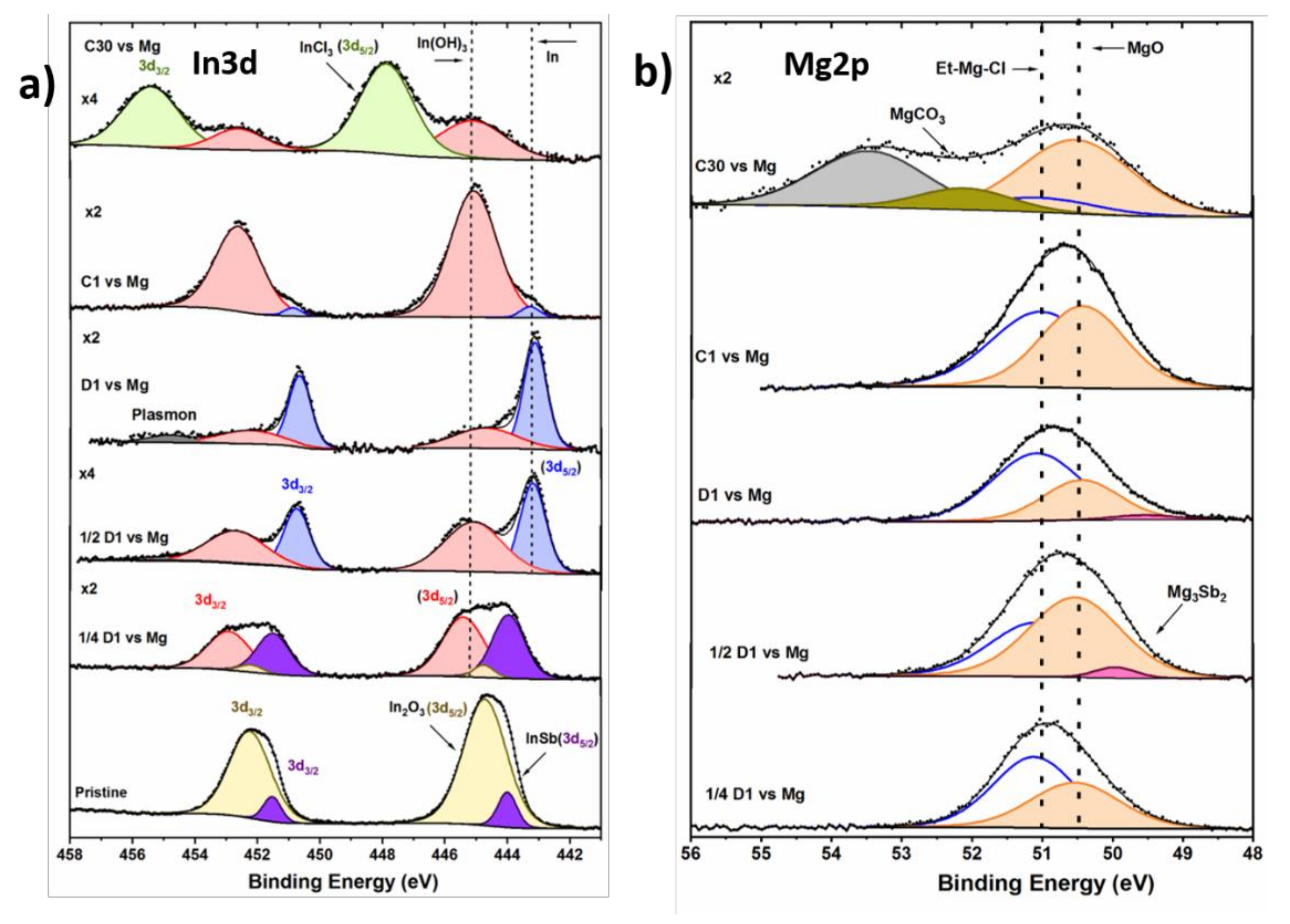
- In3d region
- Mg2p region
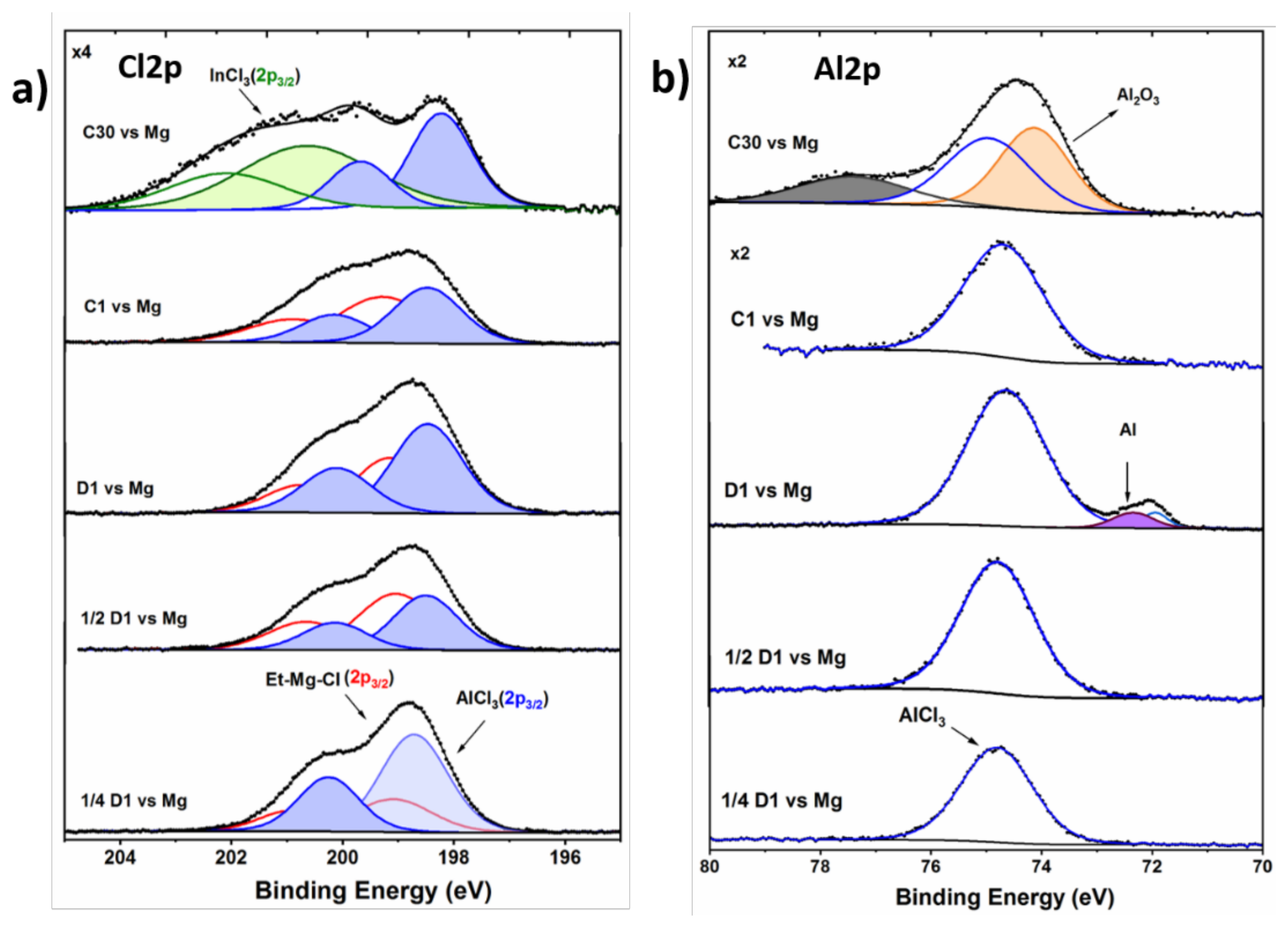
- Cl2p and Al2p regions
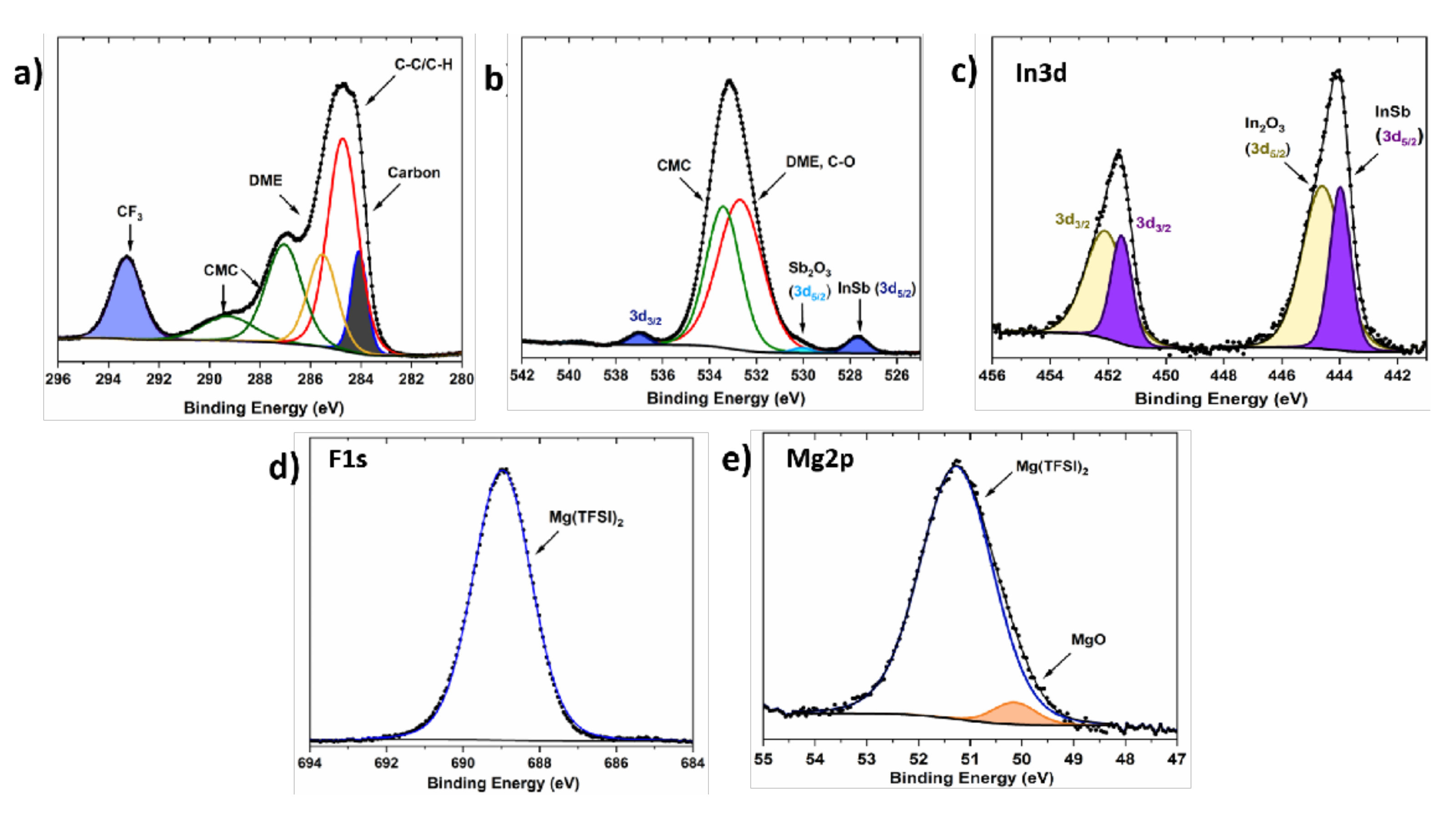
3.2.2. Surface Layer Composition in a Mg(TFSI)2-Based Electrolyte
3.2.3. Discussion
4. Conclusions
Supplementary Materials
Author Contributions
Funding
Institutional Review Board Statement
Informed Consent Statement
Data Availability Statement
Conflicts of Interest
Sample Availability
References
- Choi, J.W.; Aurbach, D. Promise and Reality of Post-Lithium-Ion Batteries with High Energy Densities. Nat. Rev. Mater. 2016, 1, 16013. [Google Scholar] [CrossRef]
- Yaksic, A.; Tilton, J.E. Using the Cumulative Availability Curve to Assess the Threat of Mineral Depletion: The Case of Lithium. Resour. Policy 2009, 34, 185–194. [Google Scholar] [CrossRef]
- Hasa, I.; Mariyappan, S.; Saurel, D.; Adelhelm, P.; Koposov, A.Y.; Masquelier, C.; Croguennec, L.; Casas-Cabanas, M. Challenges of Today for Na-Based Batteries of the Future: From Materials to Cell Metrics. J. Power Sources 2021, 482, 228872. [Google Scholar] [CrossRef]
- Ellis, B.L.; Nazar, L.F. Sodium and Sodium-Ion Energy Storage Batteries. Curr. Opin. Solid State Mater. Sci. 2012, 16, 168–177. [Google Scholar] [CrossRef]
- Dominko, R.; Bitenc, J.; Berthelot, R.; Gauthier, M.; Pagot, G.; Di Noto, V. Magnesium Batteries: Current Picture and Missing Pieces of the Puzzle. J. Power Sources 2020, 478, 229027. [Google Scholar] [CrossRef]
- Aurbach, D.; Lu, Z.; Schechter, A.; Gofer, Y.; Gizbar, H.; Turgeman, R.; Cohen, Y.; Moshkovich, M.; Levi, E. Prototype Systems for Rechargeable Magnesium Batteries. Nature 2000, 407, 724–727. [Google Scholar] [CrossRef] [PubMed]
- Gummow, R.J.; Vamvounis, G.; Kannan, M.B.; He, Y. Calcium-Ion Batteries: Current State-of-the-Art and Future Perspectives. Adv. Mater. 2018, 30, e1801702. [Google Scholar] [CrossRef] [PubMed]
- Ponrouch, A.; Frontera, C.; Bardé, F.; Palacín, M.R. Towards a Calcium-Based Rechargeable Battery. Nat. Mater. 2016, 15, 169–172. [Google Scholar] [CrossRef] [Green Version]
- Wu, X.; Leonard, D.P.; Ji, X. Emerging Non-Aqueous Potassium-Ion Batteries: Challenges and Opportunities. Chem. Mater. 2017, 29, 5031–5042. [Google Scholar] [CrossRef]
- Eftekhari, A. Potassium Secondary Cell Based on Prussian Blue Cathode. J. Power Sources 2004, 126, 221–228. [Google Scholar] [CrossRef]
- Lei, X.; Zheng, Y.; Zhang, F.; Wang, Y.; Tang, Y. Highly stable magnesium-ion-based dual-ion batteries based on insoluble small-molecule organic anode material. Energy Storage Mater. 2020, 30, 34–41. [Google Scholar] [CrossRef]
- Yoo, H.D.; Shterenberg, I.; Gofer, Y.; Gershinsky, G.; Pour, N.; Aurbach, D. Mg Rechargeable Batteries: An On-Going Challenge. Energy Environ. Sci. 2013, 6, 2265–2279. [Google Scholar] [CrossRef]
- Orikasa, Y.; Masese, T.; Koyama, Y.; Mori, T.; Hattori, M.; Yamamoto, K.; Okado, T.; Huang, Z.-D.; Minato, T.; Tassel, C.; et al. High Energy Density Rechargeable Magnesium Battery Using Earth-Abundant and Non-Toxic Elements. Sci. Rep. 2014, 4, 5622. [Google Scholar] [CrossRef] [Green Version]
- Lossius, L.P.; Emmenegger, F. Plating of Magnesium from Organic Solvents. Electrochim. Acta 1996, 41, 445–447. [Google Scholar] [CrossRef]
- Lu, Z.; Schechter, A.; Moshkovich, M.; Aurbach, D. On the Electrochemical Behavior of Magnesium Electrodes in Polar Aprotic Electrolyte Solutions. J. Electroanal. Chem. 1999, 466, 203–217. [Google Scholar] [CrossRef]
- Zhao-Karger, Z.; Bardaji, M.E.G.; Fuhr, O.; Fichtner, M. A New Class of Non-Corrosive, Highly Efficient Electrolytes for Rechargeable Magnesium Batteries. J. Mater. Chem. A 2017, 5, 10815–10820. [Google Scholar] [CrossRef]
- Mizrahi, O.; Amir, N.; Pollak, E.; Chusid, O.; Marks, V.; Gottlieb, H.; Larush, L.; Zinigrad, E.; Aurbach, D. Electrolyte Solutions with a Wide Electrochemical Window for Rechargeable Magnesium Batteries. J. Electrochem. Soc. 2007, 155, A103. [Google Scholar] [CrossRef]
- Kim, H.S.; Arthur, T.S.; Allred, G.D.; Zajicek, J.; Newman, J.G.; Rodnyansky, A.E.; Oliver, A.G.; Boggess, W.C.; Muldoon, J. Structure and Compatibility of a Magnesium Electrolyte with a Sulphur Cathode. Nat. Commun. 2011, 2, 427. [Google Scholar] [CrossRef]
- Barile, C.J.; Spatney, R.; Zavadil, K.R.; Gewirth, A.A. Investigating the Reversibility of in Situ Generated Magnesium Organohaloaluminates for Magnesium Deposition and Dissolution. J. Phys. Chem. C 2014, 118, 10694–10699. [Google Scholar] [CrossRef]
- Son, S.-B.; Gao, T.; Harvey, S.P.; Steirer, K.X.; Stokes, A.; Norman, A.; Wang, C.; Cresce, A.; Xu, K.; Ban, C. An Artificial Interphase Enables Reversible Magnesium Chemistry in Carbonate Electrolytes. Nat. Chem. 2018, 10, 532–539. [Google Scholar] [CrossRef]
- Singh, N.; Arthur, T.S.; Ling, C.; Matsui, M.; Mizuno, F. A High Energy-Density Tin Anode for Rechargeable Magnesium-Ion Batteries. Chem. Commun. 2012, 49, 149–151. [Google Scholar] [CrossRef] [PubMed]
- Arthur, T.S.; Singh, N.; Matsui, M. Electrodeposited Bi, Sb and Bi1-xSbx Alloys as Anodes for Mg-Ion Batteries. Electrochem. Commun. 2012, 16, 103–106. [Google Scholar] [CrossRef]
- Murgia, F.; Weldekidan, E.T.; Stievano, L.; Monconduit, L.; Berthelot, R. First Investigation of Indium-Based Electrode in Mg Battery. Electrochem. Commun. 2015, 60, 56–59. [Google Scholar] [CrossRef]
- Periyapperuma, K.; Tran, T.T.; Purcell, M.I.; Obrovac, M.N. The Reversible Magnesiation of Pb. Electrochim. Acta 2015, 165, 162–165. [Google Scholar] [CrossRef]
- Shao, Y.; Gu, M.; Li, X.; Nie, Z.; Zuo, P.; Li, G.; Liu, T.; Xiao, J.; Cheng, Y.; Wang, C.; et al. Highly Reversible Mg Insertion in Nanostructured Bi for Mg Ion Batteries. Nano Lett. 2014, 14, 255–260. [Google Scholar] [CrossRef] [PubMed]
- Niu, J.; Zhang, Z.; Aurbach, D. Alloy Anode Materials for Rechargeable Mg Ion Batteries. Adv. Energy Mater. 2020, 10, 2000697. [Google Scholar] [CrossRef]
- Matsui, M.; Kuwata, H.; Mori, D.; Imanishi, N.; Mizuhata, M. Destabilized Passivation Layer on Magnesium-Based Intermetallics as Potential Anode Active Materials for Magnesium Ion Batteries. Front. Chem. 2019, 7, 7. [Google Scholar] [CrossRef] [PubMed] [Green Version]
- Ikhe, A.B.; Han, S.C.; Prabakar, S.J.R.; Park, W.B.; Sohn, K.-S.; Pyo, M. 3Mg/Mg2Sn Anodes with Unprecedented Electrochemical Performance towards Viable Magnesium-Ion Batteries. J. Mater. Chem. A 2020, 8, 14277–14286. [Google Scholar] [CrossRef]
- Blondeau, L.; Foy, E.; Khodja, H.; Gauthier, M. Unexpected Behavior of the InSb Alloy in Mg-Ion Batteries: Unlocking the Reversibility of Sb. J. Phys. Chem. C 2019, 123, 1120–1126. [Google Scholar] [CrossRef]
- Blondeau, L.; Surblé, S.; Foy, E.; Khodja, H.; Gauthier, M. Electrochemical Reactivity of In-Pb Solid Solution as a Negative Electrode for Rechargeable Mg-Ion Batteries. J. Energy Chem. 2021, 55, 124–128. [Google Scholar] [CrossRef]
- Heiskanen, S.K.; Kim, J.; Lucht, B.L. Generation and Evolution of the Solid Electrolyte Interphase of Lithium-Ion Batteries. Joule 2019, 3, 2322–2333. [Google Scholar] [CrossRef]
- Fong, R.; von Sacken, U.; Dahn, J.R. Studies of Lithium Intercalation into Carbons Using Nonaqueous Electrochemical Cells. J. Electrochem. Soc. 1990, 137, 2009. [Google Scholar] [CrossRef]
- Peled, E.; Menkin, S. Review—SEI: Past, Present and Future. J. Electrochem. Soc. 2017, 164, A1703. [Google Scholar] [CrossRef]
- An, S.J.; Li, J.; Daniel, C.; Mohanty, D.; Nagpure, S.; Wood, D.L. The State of Understanding of the Lithium-Ion-Battery Graphite Solid Electrolyte Interphase (SEI) and Its Relationship to Formation Cycling. Carbon 2016, 105, 52–76. [Google Scholar] [CrossRef] [Green Version]
- Shirley, D.A. High-Resolution X-Ray Photoemission Spectrum of the Valence Bands of Gold. Phys. Rev. B 1972, 5, 4709–4714. [Google Scholar] [CrossRef] [Green Version]
- Wang, L.; Welborn, S.S.; Kumar, H.; Li, M.; Wang, Z.; Shenoy, V.B.; Detsi, E. High-Rate and Long Cycle-Life Alloy-Type Magnesium-Ion Battery Anode Enabled Through (De)Magnesiation-Induced Near-Room-Temperature Solid–Liquid Phase Transformation. Adv. Energy Mater. 2019, 9, 1902086. [Google Scholar] [CrossRef]
- Nguyen, D.-T.; Song, S.-W. Magnesium Stannide as a High-Capacity Anode for Magnesium-Ion Batteries. J. Power Sources 2017, 368, 11–17. [Google Scholar] [CrossRef]
- Xu, X.; Chao, D.; Chen, B.; Liang, P.; Li, H.; Xie, F.; Davey, K.; Qiao, S.-Z. Revealing the Magnesium-Storage Mechanism in Mesoporous Bismuth via Spectroscopy and Ab-Initio Simulations. Angew. Chem. Int. Ed. 2020, 59, 21728–21735. [Google Scholar] [CrossRef] [PubMed]
- Hong, S.; Jo, H.; Song, S.-W. Lithium Diffusivity of Tin-Based Film Model Electrodes for Lithium-Ion Batteries. J. Electrochem. Sci. Technol. 2015, 6, 116–120. [Google Scholar] [CrossRef]
- Liu, Y.; Wang, L.; Jiang, K.; Yang, S. Electro-Deposition Preparation of Self-Standing Cu-Sn Alloy Anode Electrode for Lithium Ion Battery. J. Alloys Compd. 2019, 775, 818–825. [Google Scholar] [CrossRef]
- Nguyen, G.T.H.; Nguyen, D.-T.; Song, S.-W. Unveiling the Roles of Formation Process in Improving Cycling Performance of Magnesium Stannide Composite Anode for Magnesium-Ion Batteries. Adv. Mater. Interfaces 2018, 5, 1801039. [Google Scholar] [CrossRef]
- Delpuech, N.; Dupré, N.; Mazouzi, D.; Gaubicher, J.; Moreau, P.; Bridel, J.-S.; Guyomard, D. Lestriez, B. Correlation between irreversible capacity and electrolyte solvents degradation probed by NMR in Si-based negative electrode of Li-ion cell. Electrochem. Commun. 2013, 33, 72–75. [Google Scholar] [CrossRef]
- Mandli, A.R.; Kaushik, A.; Patil, R.S.; Naha, A.; Hariharan, K.S.; Kolake, S.M.; Han, S.; Choi, W. Analysis of the effect of resistance increase on the capacity fade of lithium ion batteries. Energy Res. 2019, 43, 2044–2056. [Google Scholar] [CrossRef]
- Talaie, E.; Bonnick, P.; Sun, X.; Pang, Q.; Liang, X.; Nazar, L.F. Methods and Protocols for Electrochemical Energy Storage Materials Research. Chem. Mater. 2017, 29, 90–105. [Google Scholar] [CrossRef]
- Kumar, R.; Tokranov, A.; Sheldon, B.W.; Xiao, X.; Huang, Z.; Li, C.; Mueller, T. In Situ and Operando Investigations of Failure Mechanisms of the Solid Electrolyte Interphase on Silicon Electrodes. ACS Energy Lett. 2016, 1, 689–697. [Google Scholar] [CrossRef]
- Attias, R.; Salama, M.; Hirsch, B.; Goffer, Y.; Aurbach, D. Anode-Electrolyte Interfaces in Secondary Magnesium Batteries. Joule 2019, 3, 27–52. [Google Scholar] [CrossRef] [Green Version]
- Pantea, D.; Darmstadt, H.; Kaliaguine, S.; Roy, C. Electrical Conductivity of Conductive Carbon Blacks: Influence of Surface Chemistry and Topology. Appl. Surf. Sci. 2003, 217, 181–193. [Google Scholar] [CrossRef]
- Pantea, D.; Darmstadt, H.; Kaliaguine, S.; Sümmchen, L.; Roy, C. Electrical Conductivity of Thermal Carbon Blacks: Influence of Surface Chemistry. Carbon 2001, 39, 1147–1158. [Google Scholar] [CrossRef]
- El Ouatani, L.; Dedryvère, R.; Ledeuil, J.-B.; Siret, C.; Biensan, P.; Desbrières, J.; Gonbeau, D. Surface Film Formation on a Carbonaceous Electrode: Influence of the Binder Chemistry. J. Power Sources 2009, 189, 72–80. [Google Scholar] [CrossRef]
- Philippe, B.; Dedryvère, R.; Allouche, J.; Lindgren, F.; Gorgoi, M.; Rensmo, H.; Gonbeau, D.; Edström, K. Nanosilicon Electrodes for Lithium-Ion Batteries: Interfacial Mechanisms Studied by Hard and Soft X-Ray Photoelectron Spectroscopy. Chem. Mater. 2012, 24, 1107–1115. [Google Scholar] [CrossRef]
- Aswal, D.K.; Muthe, K.P.; Tawde, S.; Chodhury, S.; Bagkar, N.; Singh, A.; Gupta, S.K.; Yakhmi, J.V. XPS and AFM Investigations of Annealing Induced Surface Modifications of MgO Single Crystals. J. Cryst. Growth 2002, 236, 661–666. [Google Scholar] [CrossRef]
- Madec, L.; Gachot, G.; Coquil, G.; Martinez, H.; Monconduit, L. Toward Efficient Li-Ion Cells at High Temperatures: Example of TiSnSb Material. J. Power Sources 2018, 391, 51–58. [Google Scholar] [CrossRef]
- Bodenes, L.; Darwiche, A.; Monconduit, L.; Martinez, H. The Solid Electrolyte Interphase a Key Parameter of the High Performance of Sb in Sodium-Ion Batteries: Comparative X-Ray Photoelectron Spectroscopy Study of Sb/Na-Ion and Sb/Li-Ion Batteries. J. Power Sources 2015, 273, 14–24. [Google Scholar] [CrossRef]
- Li, W.; Liu, T.; Zhang, J.; Peng, N.; Zheng, R.; Yu, H.; Bai, Y.; Cui, Y.; Shu, J. Commercially Available InSb as a High-Performance Anode for Secondary Batteries towards Superior Lithium Storage. Sustain. Energy Fuels 2019, 3, 2668–2674. [Google Scholar] [CrossRef]
- Mohammad, I.; Blondeau, L.; Foy, E.; Leroy, J.; Leroy, E.; Khodja, H.; Gauthier, M. Nanostructured Intermetallic InSb as a High-Capacity and High-Performance Negative Electrode for Sodium-Ion Batteries. Sustain. Energy Fuels 2021, 5, 3825–3835. [Google Scholar] [CrossRef]
- Teterin, Y.A.; Maslakov, K.I.; Murav’ev, E.N.; Teterin, A.Y.; Bulychev, N.A.; Meshkov, B.B.; Stepnov, D.S. X-Ray Photoelectron Spectroscopy Study of Indium Tin Mixed Oxides on the Surface of Silicate Glass. Inorg. Mater. 2020, 56, 482–493. [Google Scholar] [CrossRef]
- Loh, J.Y.Y.; Kherani, N.P. X-Ray Photospectroscopy and Electronic Studies of Reactor Parameters on Photocatalytic Hydrogenation of Carbon Dioxide by Defect-Laden Indium Oxide Hydroxide Nanorods. Molecules 2019, 24, 3818. [Google Scholar] [CrossRef] [PubMed] [Green Version]
- Copperthwaite, R.G.; Kunze, O.A.; Lloyd, J.; Neely, J.A.; Tuma, W. Surface Analysis of InSb by X-Ray Photoelectron Spectroscopy (XPS). Z. Nat. A 1978, 33, 523–527. [Google Scholar] [CrossRef]
- Sahu, S.; Manivannan, A.; Shaik, H.; Mohan Rao, G. Local Structure of Amorphous Ag5In5Sb60Te30 and In3SbTe2 Phase Change Materials Revealed by X-Ray Photoelectron and Raman Spectroscopic Studies. J. Appl. Phys. 2017, 122, 015305. [Google Scholar] [CrossRef]
- Hieu, L.T.; So, S.; Kim, I.T.; Hur, J. Highly Reversible Lithiation/Delithiation in Indium Antimonide with Hybrid Buffering Matrix. Int. J. Energy Res. 2021, 45, 16145–16154. [Google Scholar] [CrossRef]
- Hu, Y.; Zhou, D.-Y.; Wang, B.; Wang, Z.-K.; Liao, L.-S. Chlorinated Indium Tin Oxide Electrode by InCl3 Aqueous Solution for High-Performance Organic Light-Emitting Diodes. Appl. Phys. Lett. 2016, 108, 153303. [Google Scholar] [CrossRef]
- Berestok, T.; Guardia, P.; Portals, J.B.; Estrade, S.; Llorca, J.; Peiro, J.; Cabot, A.; Brock, S.L. Surface Chemistry and Nano-/Microstructure Engineering on Photocatalytic In2S3 Nanocrystals. Langmuir 2018, 34, 6470–6479. [Google Scholar] [CrossRef] [PubMed] [Green Version]
- Aurbach, D.; Weissman, I.; Gofer, Y.; Levi, E. Nonaqueous Magnesium Electrochemistry and Its Application in Secondary Batteries. Chem. Rec. 2003, 3, 61–73. [Google Scholar] [CrossRef] [PubMed]
- Nguyen, D.-T.; Tran, X.M.; Kang, J.; Song, S.-W. Magnesium Storage Performance and Surface Film Formation Behavior of Tin Anode Material. ChemElectroChem 2016, 3, 1813–1819. [Google Scholar] [CrossRef]
- Wang, Z.; Bandyopadhyay, A.; Kumar, H.; Li, M.; Venkatakrishnan, A.; Shenoy, V.B.; Detsi, E. Degradation of Magnesium-Ion Battery Anodes by Galvanic Replacement Reaction in All-Phenyl Complex Electrolyte. J. Energy Storage 2019, 23, 195–201. [Google Scholar] [CrossRef]
- Jay, R.; Tomich, A.W.; Zhang, J.; Zhao, Y.; De Gorostiza, A.; Lavallo, V.; Guo, J. Comparative Study of Mg(CB11H12)2 and Mg(TFSI)2 at the Magnesium/Electrolyte Interface. ACS Appl. Mater. Interfaces 2019, 11, 11414–11420. [Google Scholar] [CrossRef]


| InSb/Mg Cell | Before Cycling | After Cycling |
|---|---|---|
| R1 (Ω) | 98 | 24 |
| R2 (Ω) | 6 | 12 |
| R3 (Ω) | − | 3 |
| W (Ω s−1/2) | 3300 | 100 |
| CPE1 (F sa−1) | 0.56 × 10⁻⁶ | 3.6 × 10⁻⁶ |
| CPE2 (F sa−1) | − | 2 × 10⁻⁴ |
Publisher’s Note: MDPI stays neutral with regard to jurisdictional claims in published maps and institutional affiliations. |
© 2021 by the authors. Licensee MDPI, Basel, Switzerland. This article is an open access article distributed under the terms and conditions of the Creative Commons Attribution (CC BY) license (https://creativecommons.org/licenses/by/4.0/).
Share and Cite
Mohammad, I.; Blondeau, L.; Leroy, J.; Khodja, H.; Gauthier, M. Influence of Electrolyte on the Electrode/Electrolyte Interface Formation on InSb Electrode in Mg-Ion Batteries. Molecules 2021, 26, 5721. https://doi.org/10.3390/molecules26185721
Mohammad I, Blondeau L, Leroy J, Khodja H, Gauthier M. Influence of Electrolyte on the Electrode/Electrolyte Interface Formation on InSb Electrode in Mg-Ion Batteries. Molecules. 2021; 26(18):5721. https://doi.org/10.3390/molecules26185721
Chicago/Turabian StyleMohammad, Irshad, Lucie Blondeau, Jocelyne Leroy, Hicham Khodja, and Magali Gauthier. 2021. "Influence of Electrolyte on the Electrode/Electrolyte Interface Formation on InSb Electrode in Mg-Ion Batteries" Molecules 26, no. 18: 5721. https://doi.org/10.3390/molecules26185721