Article

3D Printed Unibody Lab-on-a-Chip: Features Survey and Check-Valves Integration †

Optical Devices Laboratory, Department of Physics, Chemistry and Biology, Linköping University, S58183 Linköping, Sweden
*
Author to whom correspondence should be addressed.
This paper is an extended version of our paper published in the 2nd International Conference on Microfluidic Handling Systems, Freiburg, Germany, 8–10 October 2014.
These authors contributed equally to this work.
Micromachines 2015, 6(4), 437-451; https://doi.org/10.3390/mi6040437
Submission received: 6 February 2015 / Revised: 31 March 2015 / Accepted: 2 April 2015 / Published: 7 April 2015

Abstract

:
The unibody lab-on-a-chip (ULOC) concept entails a fast and affordable micro-prototyping system built around a single monolithic 3D printed element (unibody). A consumer-grade stereo lithography (SL) 3D printer can configure ULOCs with different forms of sample delivery, transport, handling and readout, while minimizing material costs and fabrication time. ULOC centralizes all complex fabrication procedures and replaces the need for clean room resources, delivering prototypes for less than 1 US$, which can be printed in 10 min and ready for testing in less than 30 min. Recent examples of ULOC integration of transport, chemical sensing for optical readout and flow mixing capabilities are discussed, as well as the integration of the first check-valves for ULOC devices. ULOC valves are strictly unidirectional up to 100 psi, show an exponential forward flow behavior up to 70 psi and can be entirely fabricated with the ULOC approach.

1. Introduction

Conventional microfabrication techniques involve specialized resources and skills beyond the scope of many potential lab-on-a-chip (LOC) users [1,2]. Simplified processes, which facilitate access to LOC fabrication, still require dedicated skills and expensive clean room infrastructure [2,3,4].
Emerging additive 3D structuring, like in thermoplastic extrusion systems [5,6,7] and micro-stereo lithography (SL) platforms [3,7,8,9,10], have the potential to greatly simplify fabrication and minimize infrastructure costs.
Here, we discuss the latest results on LOC devices fabricated with consumer-grade SL 3D printers, and, in particular, the concept of unibody LOC (ULOC [10]) and its possibility to integrate essential components and LOC principles. The ULOC concept is inspired by Apple®’s (Cupertino, CA, USA) unibody design, which is used to fabricate the body of such computers. The unibody replaces multiple parts by a single monolithic structure directly machined from a slab of aluminum alloy, which confers structural strength, minimizes the number of parts and simplifies the assembly of the functional components. The ULOC architecture exploits such a unibody idea, to create a single monolithic 3D printed microstructure that hosts the LOC’s functional components and transfers all complex fabrication tasks to the printer.
Low cost ULOCs are possible due to the resolution presently achievable with consumer-grade SL 3D printers [11]. Previous demonstrations of 3D printed fluidics, made with affordable printers [6], had restrictions on the resolution and surface roughness, which prevented regular LOC channel geometries and simple sealing procedures. In contrast, SL 3D printers support resolutions of 50 μm [9,10], and surface roughness under 200 nm, which permits arbitrary long, but dimensionally uniform channels, since they can be configured as open channels to facilitate the release of uncured resin and can be simply sealed with regular adhesive tape.
For similar resolutions, other additive systems cost 10- to 100-times more than the Miicraft printer used in this work (2290 US$) [10,11], but in order to exploit these capabilities, ULOC designs must be carefully conceived of to define all precision features on the stacking plane, which also leads to minimizing the structures’ height and, consequently, reduces printing time and resin consumption.
As any 3D printing technology, ULOC supports drastic modifications during the development process, which are uncompromised by the legacy of previous designs, such as reusing masks in classical microfabrication. This freedom to evolve designs is matched by the low development costs, typically ~0.5 US$/prototype, the affordable initial investment and the possibility to entirely operate outside a clean room environment.
ULOC can accommodate different operation principles, such as continuous flow and passive transport, as well as hosting paper fluidics [12] and microbeads [10,13]. In addition to these possibilities, the importance of actuation and flow control [14] is another relevant aspect to demonstrate with unibody architectures. The integration of a key fluidic component, such as robust unidirectional valves [15,16], is here demonstrated feasible and simple to implement, thus expanding the toolbox supported by this fabrication approach.

2. Experimental Section

2.1. Device Fabrication

Device structures were designed with free computer aided design (CAD) software for Mac (Autodesk® Inventor® Fusion, Autodesk Inc., San Rafael, CA, USA) on an Apple computer (13-inch, late 2010, 1.86 GHz Intel Core 2 Duo, 4 GB 1067 MHz, OS X 10.8.3–10.10.1, Apple Inc., Cupertino, CA, USA).
The devices were fabricated with a Miicraft® 3D printer (Rays Optics Inc., Hsin-Chu, Taiwan), which is a stereo lithography (SL) platform (2299 US$) with 450 ppi (~56 μm) lateral resolution and 50-μm resolution in the vertical direction. The printer is also capable of 5-μm resolution in the z-axis, but this requires a specialized driver for a commercial CAD package or upgrading to the recently-released Miicraft® Plus printer. In this work, the 50-μm resolution was the only configuration available.
CADs were exported as .stl mesh files and converted to bitmap exposure patterns by the Miicraft® Suite software (Rays Optics Inc.) provided with the 3D printer. Further edition possibilities have been reported elsewhere [9,10].
After optimization, devices were printed in the following conditions of exposure time, printing speed and vertical step size: 7 s, 2 cm/h, 50 μm. After printing, the devices were sonicated (FinnSonic m15, FinnSonic Oy, Lahti, Finland) in industrial-grade ethanol for 20 s and air-dried.
The printer uses a proprietary resin (138 US$/500 mL), with undisclosed formulations of a modified acrylate oligomer and monomer in combination with an epoxy monomer, a photo initiator and additives [11]. For this resin’s cost, the check-valve testing device, which weighted 3 g, corresponded to 0.82 US$/device. Optimized devices, typically minimizing the area and thickness, have been fabricated at 0.41 US$/device [17].
Unibody surface roughness was characterized with a stylus profiler (Dektak 6, Veeco Instrument Inc., Plainview, NY, USA) along 1-mm tracks resolved in 6000 points. The average roughness was 182 nm for the finished templates [9], which enables direct sealing with adhesive tape (3M Ruban Adhesive Scotch® Nastro Adhesive, 3M Europe, Diegem, Belgium) [10]. Unibody designs exploit this aspect by simplifying the fabrication to a single monolithic 3D printed structure, or unibody, around which the device functional components are assembled.
The same low surface roughness enabled efficient sealing with flat polydimethylsiloxane (PDMS) film, which was used to create the elastic element for the integrated check-valves. To fabricate the PDMS film, Dow Corning Sylgard 184 base and curing agent were mixed in a 10:1 proportion and stirred in a cup for 2 min. The mixture was degassed in a desiccator connected to a rotary pump for 30 min and subsequently poured on glass and spread to form a film between 300- and 500-μm thick, which was cured at 65 °C for 1 h in an environmental oven (Gallenkamp incubator, Weiss Technik, Loughborough, UK). The PDMS elements for the check-valves were cut with a blade in sectors of approximately 1.5 × 2 mm2 and placed in the unibody seats with a tweezer.
The devices were subsequently sealed with adhesive tape. Excess tape was trimmed with a cutter, and the tape was pressed against the unibody surface with a cotton tip in order to eliminate air trapped in small blisters. The total fabrication time, including the PDMS assembly and sealing, to produce a device ready for testing was less than 30 min.
Mixers were firstly front-sealed with adhesive tape, and in the model incorporating beads (G1145 SIGMA Glass beads, acid-washed, 150–212 μm (70–100 USA sieve), Sigma-Aldrich, St. Louis, MO, USA), these were delivered dry from the backside of the hole. Excess beads were brushed away from the unibody and the backside immediately sealed with adhesive tape [10].
The devices were completed with the manual insertion of silicone tubing (Esska.de GmbH, Hamburg, Germany) in the unibody printed connector. The connector diameter, required for proper sealing with the tubing was: 2.4 mm for a tubing inner diameter of 1.5 mm.
For lateral flow devices, the microchannels were filled with cellulose paste, made of cellulose powder (S3504 SIGMA Sigmacell Cellulose, Type 20, 20 μm, Sigma-Aldrich) mixed with water and squeegeed into the channels with a metal spatula. Surface excess was removed with a humid cotton tip before the paste dried, and the channels were left to dry for 10 min before pipetting the detection chemistry in the distal end of the structure. Once pipetted (Eppendorf Reference 0.5–10 μL), the device was immediately dried with an air jet to secure localization of the detection chemistry. The lateral flow devices did not require any further sealing or tuning. Further details of the detection chemistry have been reported elsewhere [10].

2.2. Check-Valve Characterization

The device in Figure 3a was specifically designed to optically characterize the forward and backward check-valve behavior simultaneously. The device was connected to two reservoirs containing rhodamine and fluorescein aqueous solutions. The reservoirs were connected to mechanical valves and to a pressure micro-injector (PMI-200, Dagan Corporation, Minneapolis, MN, USA). The injector delivered 100 ms-long pressure pulses to only one reservoir at time (the second one blocked with its corresponding mechanical valve), between 10 and 70 psi, at 10-psi intervals.
Every time a pressure pulse was applied, one check-valve was tested in the forward direction and simultaneously the opposite in the backward direction.
The device was video recorded during the experiment using a Samsung Galaxy Note 2 (Samsung, Seoul, South Korea), 8-Mpix rear side camera operating in full HD video acquisition (30 fps). Background illumination was provided by an iPod Touch screen (4th generation, 960 × 640 pixel screen resolution, with iOS 6 (Apple Inc., Cupertino, CA, USA), running Led Torch v1.37 app (http://www.smallte.ch), set to pure white (RGB 255, 255, 255).
For quantification purposes, the video was decomposed in individual frames using Adapter 2.1.0 (Macroplant LLC, McKinney, TX, USA) for Mac. Each video frame, which corresponds to a 33.3-ms interval, enabled measuring the displaced fluid by each pressure pulse (Figure 3b). Displacement quantification was made by subtracting subsequent video frames. ImageJ was used for image subtraction and to measure displaced distances in pixels, which were correspondingly calibrated in μm (Figure 3b). Since the channel dimensions are known, the flow rates corresponding to the displacements could thus be calculated. Error bars are computed upon pulse repetition up to 30 psi, whereas at higher pressures, the computing interval had to be reduced, which is reflected in larger error bars.
No leakage at 100-psi backward pressure is illustrated in the inserts in Figure 3c. The blue channel images are used to clearly visualize the location of colored substances, showing that none reach beyond the valve seat.

2.3. Cell Viability

Unibody biocompatibility was tested with the Almar Blue cell viability assay. Fibroblasts from Xenopus laevis were cultured in Leibovitz’s L-15 medium, supplemented with fetal bovine serum and penicillin-streptomycin-glutamine (all reagents were from Life technologies) as previously described [18].
For the viability assays, the cells were trypsinized and suspended in growth media to a concentration of 7 × 10⁴ cells/mL. Two additional concentrations of cell solutions were prepared by diluting this solution with growth media 1:2 and 1:4. A volume of 300 μL of the cell solutions, and pure growth media were then incubated on the different substrates and configurations located in 48-well plates (SPL Life Sciences, Pocheon-si, Korea) for 48 h. Two materials in two different configurations were tested: 100 μm-thick unibody resin placed at the bottom (occupying 50% of the well bottom area) and rolled around the wall of the individual wells and adhesive tape as the one used for sealing the channels, also at the bottom and on the wall of the individual wells. Cells incubated in empty wells were used as the control.
The AlamarBlue® assay was used to estimate cell viability after contact with the different materials. After 20 h of incubation, 30 μL of the resazurin-solution (10 mM resazurin (Chroma, Münster, Germany) in 0.7× PBS) was added and incubation continued [19]. After 24 h, 150 μL of the medium were transferred to a new 96-well microplate, and the fluorescence of reduced resazurin (resorufin) was measured using a microplate reader (FLUOstar Galaxy, BMG LABTECH GmbH, Offenburg, Germany) at wavelengths of 544 (±12) nm excitation and 590 (±10) nm emission.
The viability of the cells was expressed in % cell viability of the control cells. Fluorescence as a function of cell number was used in the control conditions to determine linearity and, thus, to compute the viability as a percentage of the control response.

3. Results and Discussion

Consumer-grade thermo polymer extrusion 3D printers [7], which are easy to operate, versatile and simple to maintain, are capable of microstructuring with resolutions in the 300–50 μm range [6,7] and a minimum layer height down to 25 μm [20]. On the other hand, affordable SL 3D printers, although limited to less materials and marginally more complex to operate, also deliver resolutions in the 50-μm range [8,9,10,11]. In the particular case of the ULOC architecture presented in this work, the resolution is not the dominant factor that simplifies fabrication, minimizes materials and makes the workflow robust and reliable. Central to ULOC construction is the remarkable surface finish of the stacking plane [9], which allows open channel sealing with regular adhesive tape, and the correlated advantage of printing open channels that enable easy removal of uncured resin and consistent dimensional features all along the layout [10].
Figure 1 illustrates the generic characteristics of an SL 3D printer that delivers less than 200-nm surface roughness. In an SL printer, each layer of the 3D printout is exposed to UV light through a digital micromirror device (DMD) that configures the layout of each stacking plane. The ppi count of this DMD element was 450 ppi and, at 854 × 480 pixels, defines the x-y resolution, at about 50 μm.
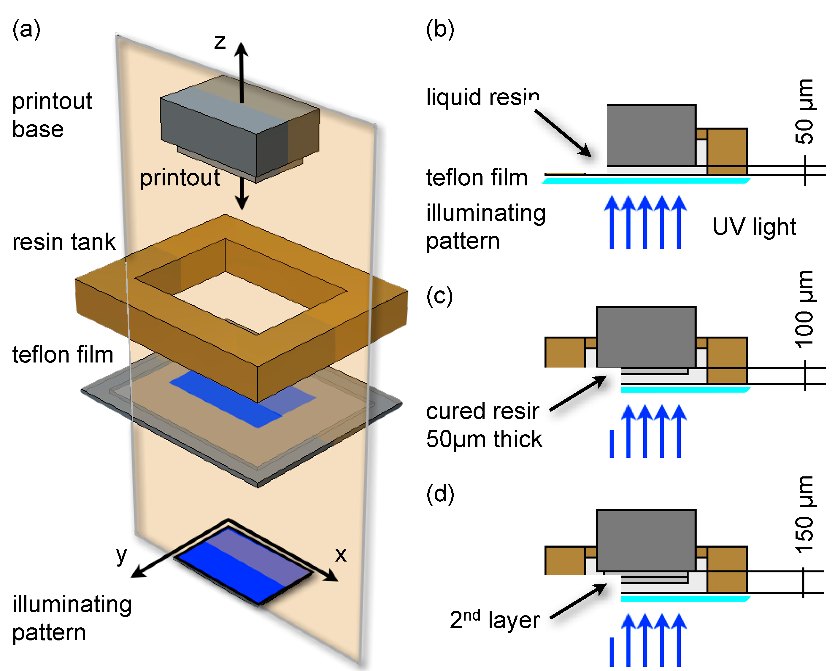
Figure 1a shows the spatial arrangement of the printer parts. A tank with a transparent bottom holds the printing resin in liquid form. The bottom of this tank is a 127 μm-thick Teflon film (DuPont™ Teflon® FEP film, Dupont, Wilmington, DE, USA), stretched by contact with a quartz glass (not indicated in the figure). The printout emerges adhered to a metal base that the printer positions in the z-axis at 50-μm resolution. Figure 1b,c describes the 3D build-up of the printout. Initially, the base is positioned at 50 μm from the Teflon surface, leaving a gap entirely filled with liquid resin (Figure 1b). When the resin is exposed (4 to 10 s, depending on the design), it cures through the gap and adheres to the surface of the metal base, capturing its texture in the printout, whereas the side in contact with the Teflon film does not adhere to the surface, but yet captures its surface texture. In the next step, the base is raised by 50 μm, and a new exposure occurs (Figure 1c). In this case, the layer binds to the previous cured layer, and the process is repeated for subsequent stacking planes (Figure 1d).
Figure 1. (a) 3D scheme of a generic stereo lithography (SL) printer arrangement. The illuminating pattern is provided by a digital micro-mirror device (DMD), which defines the x-y resolution of the UV exposure. Liquid resin in the tank is confined between the printout base and the tank bottom, which is a transparent Teflon film. (b) Cross-section of (a) indicating the first printed layer. A 50-μm gap between the Teflon surface and the printout base is set, and upon exposure, the far side of the layer sticks to the metal surface of the printout base. Both cured layer surfaces copy the surface textures of the metal and Teflon, respectively. (c) The printout base is raised 50 μm, and the next layer is exposed, binds to the previous layer and adheres through this to the metal base. (d) The printout base is raised another 50 μm, and a third layer is exposed. The process is repeated until completing the printout, which retains in its bottom surface the Teflon texture captured in the last exposure.
Micromachines 06 00437 g001
When the printout is ready, the last surface retains the Teflon texture, which, except for scratches and localized damage due to usage, typically renders a roughness under 200 nm. It is worth noticing that not only the final surface retains this surface finishing, but also any last exposed surfaces, such as the bottom of any embossed channel.
The described printing mechanism also suggests that intentionally decorating the Teflon surface with a texture is a potential alternative to introduce some level of nano-structuring on selected ULOC surfaces.
The discussed properties also apply for the fabrication of 3D printed templates for conventional PDMS on glass LOC [9]. In that case, the channels are defined as raised features, and the small surface roughness transferred to the PDMS replica enables direct sealing onto the glass surface.
Despite the ULOC benefits presented in this work, the same type of printer can be used in a more conventional fashion, without constraints in the printing configuration, but sacrificing the surface finish of the stacking plane. The unconstrained printer utilization has been used to fabricate 3D micromixers, droplet fluidics for liquid-liquid extraction and isotachophoresis separation devices. In contrast with ULOC, mixers grown perpendicularly to the stacking plane can take five hours to print at a cost of 20 US$ in resin [8].

3.1. Assembly, Connectors, Transport, Mixers and Detection

Besides its simplicity, versatility and economy, the possibility to integrate specialized 3D geometries and to host established LOC configurations are other important aspects of ULOC. Figure 2 collects demonstrated examples of such integration possibilities. Figure 2a corresponds to a three-channel design configured for H2O2 fluorescence detection on a microscope stage [10]. The 3D printed unibody solves several demanding fabrication aspects in a single procedure that takes about 10 min (depending on the printer settings). The ULOC integrates printed connectors (Figure 2b) that can directly plug into standard silicone tubing (in this case, prepared for 1.5- mm inner diameter tubing), either for continuous flow operation or for pipetting of fixed volumes. The three-channel configuration enables one to measure an unknown sample and the two limits of the calibration range, which in that case [10] was configured to resolve the lower limit of H2O2 in urine for whole body oxidative stress monitoring [21], an indicator associated with the development of numerous serious conditions, such as cancer [22] and heart failure [23].
To facilitate fabrication, the functional surface was separately prepared on a large PDMS area, which was subsequently cut and attached to the unibody. To allow this type of assembly procedure, regions sealed with adhesive tape and the region sealed with the PDMS film must stay separately confined. Figure 2c illustrates the 3D printed 100 μm-thick channel roof that permits such separate sealing of contiguous sectors. Closed channels can be obviously fabricated with the 3D printer; however, the ULOC principle precludes this approach for a number of reasons. Firstly, only free surfaces retain the quality finish achievable by the Miicraft printer, whereas the free standing surface of a printed ceiling is exposed without backing on a previous layer and captures the exposure profile instead of replicating the Teflon surface. This leads to poor reproducibility, since the exposure profile will change with the curing time, which can vary from 4 to 10 s, depending on the design, and introduces spurious fluctuations in the channels cross-section. Collaterally, closed channels are more difficult for removing uncured resin, thus demanding longer sonication and rinsing cycles that erode the benefits of the fast prototyping method. Thus, the roofed channels in Figure 2c are a compromise, which is only long enough to permit separate sealing of different sectors, and yet, short to remain easy to clean.
The open channel configuration of the unibody printouts also offers a very versatile way to integrate paper fluidics and to configure passive transport devices [10,12,24]. Classical paper fluidics uses cellulose membranes to control lateral flow transport and is an established technology in diagnostics and home tests [12]. Modern paper fluidics achieves more complex layouts by confining paper channels within hydrophobic boundaries, which can be produced by photolithography [25] or directly printed with solid ink [26] printers. The unibody printout offers a third alternative, to easily reconfigure a design, such as that in Figure 2a, into a paper fluidic device, by filling the printed channels with cellulose paste, a straightforward procedure that renders well-defined paper conduits. The concept has been demonstrated on a similar design as Figure 2b, but functionalized for colorimetric glucose detection within the clinical range [10].
Mixing is a common preparatory stage in chemical analyses and, accordingly, another important function to integrate in ULOC. Microfluidic dimensions favor laminar flow regimes, rendering mixing a slow diffusional process; thus, designs favoring turbulence to improve the mixing performance are required [27]. Since the bodies in ULOC designs are conceived of to accommodate the connectors, they entail a thickness of about 2.5 to 3 mm, which can be employed for fluidic purposes. In contrast with classical fabrication methods, introducing multiple depths in ULOC designs does not imply extra fabrication steps, masks or alignments, and exploiting the unibody thickness in the design permits small footprint solutions. Figure 2d illustrates this possibility.
A localized geometric feature, such as a 1-mm diameter hole at the join of the input channels, provides a compact architecture that improves the mixing performance (Figure 2d). In addition, this space can also accommodate glass microbeads, which can be used to further improve turbulence. The associated image illustrates the performance of the mixer hosting the microbeads and shows mixed flows at 30 μL/min in the first quarter of the serpentine, whereas a diffusional mixer (without the through hole) does not mix the flow in the complete extension of this device [10]. The compact layout and simple fabrication of the ULOC alternative can be further appreciated by comparing with a mixer in PDMS on glass (Figure 2e). The template was also 3D printed with the Miicraft printer [9], which is already a significant simplification from the fabrication of templates with conventional photolithography. Here, the connectors were integrated using a template with 2 mm-high pillars, which were used as a guide for silicone tubing that was plugged into the template before pouring the PDMS. In this way, the PDMS replica integrates the silicone connectors and can be directly attached to a glass slide and used. Thick features, such as these guiding pillars, complicate classical microfabrication and add multiple fabrication steps, whereas it does not tax the fabrication of 3D printed templates, which take the same effort regardless of the number of different thicknesses involved.
The chaotic mixer design in Figure 1e has the same general cross-section and was measured at the same flow rate as the ULOC mixer [9,10], but required more than 80% of the total extension to mix the streams; additionally, the motif used for the chaotic mixer must decorate the entire channel. The ULOC alternative did not involve PDMS processing, and after sonication, the unibody was simply sealed with adhesive tape and ready to operate [10].
Figure 2. Collection of recent unibody lab-on-a-chip (LOC) integration examples. (a) CAD of ULOC design, integrating connectors, three channels for embedded references and sectors suitable for independent sealing. The green frame highlights the detection area. (b) 3D detail and image of the integrated connectors, designed for tight plugging to 1.5 mm silicone tubing. (c) Detection region showing two sectors sealed with adhesive tape (red frame) and one sector closed with a H2O2-functionalized PDMS film (orange frame). The cross-section along the AA’ segment shows the 100-μm roofed channels used to independently seal different sectors. For detection, the upper PDMS side is imaged with an epi-fluorescence microscope [10]. (d) CAD design of an ULOC micromixer and details of geometric features used to enhance the mixing performance. The 1-mm diameter hole and the joint of the input channels are a very compact feature that improves turbulence and can be used to host microbeads that further improve performance. The image shows the mixing of two solutions at a 30 μL/min flow rate with integrated beads. (e) For comparison with ULOC mixers, a classical PDMS on glass chaotic mixer device fabricated with a 3D printer template is shown [9]. The fabrication demands more steps, and the chaotic mixer has a larger footprint than the ULOC feature, yet lesser performance. Edited from [9,10], reproduced by permission of The Royal Society of Chemistry.
Micromachines 06 00437 g002

3.2. Unidirectional Valves

Benchmark target assays, such as immunosorbent assays or surface plasmon resonance measurements [28], require sequentially delivered unidirectional flows [15] of samples and reagents to the detection area. Robust passive check-valves suitable for integration in ULOCs are thus key components to avoid reflow, and to establish essential logic elements in fluidic circuits. Critical for field uses is also the possibility to operate within a broad range of pressures to allow simple pressurization mechanisms, such as in finger pumps [29]. Here, we present the design of check-valves that exploit the characteristics of the ULOC principles for cost-effective fast prototyping and integration of common LOC materials, such as polydimethylsiloxane (PDMS), for the valve action.
Figure 3. 
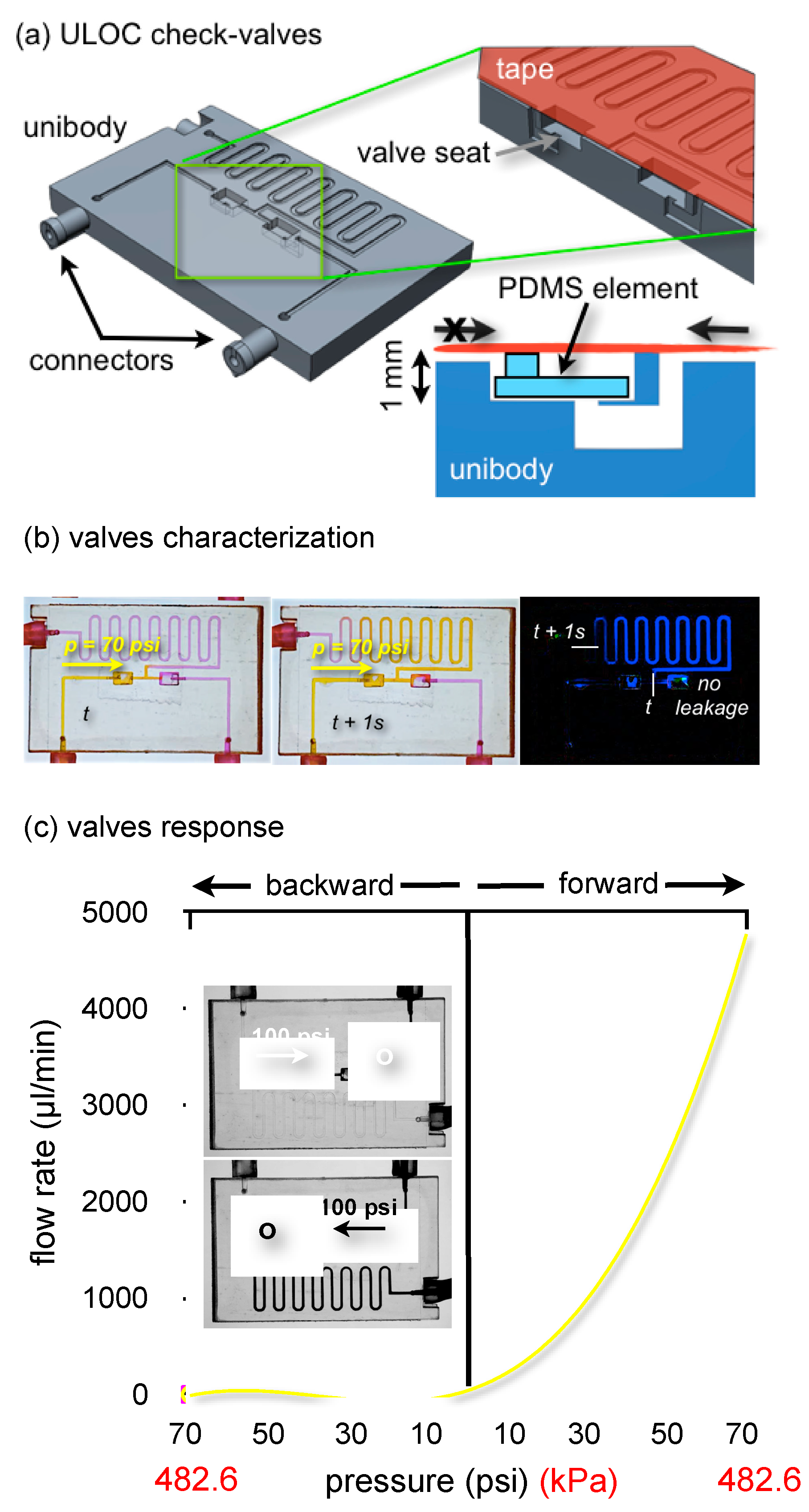
Twin check-valves integrated in a ULOC test device. (a) CAD of the ULOC design. The green frame highlights the valve seats and the cross-section of one valve. The asymmetric valve seat is directionally sealed by a 200 μm-thick and ~2 × 1.5-mm2 PDMS element. (b) Example of flow rate characterization using video frame subtraction and controlled pressure pulses. (c) Twin check-valves response using 100 ms-long pressure pulses (back and forward) between 10 and 70 psi at 10-psi intervals. Inserts show zero backward flow at 100 psi.
Micromachines 06 00437 g003
Figure 3a shows the valve design integrated in a ULOC conceived of for valve characterization. The 3D printed unibody integrates tight connectors to 1.5-mm I.D. silicone tubing and the seats for two PDMS film valves working in opposition, thus allowing the simultaneous characterization of the forward and backward behavior of each valve.
The valve seat is a 1-mm deep, 2 × 3 mm2 rectangular sector with a square 500-μm side orifice on one side. The 3D printer enables one to create this asymmetric geometry where the PDMS sits. Since the seat is a free surface, its small roughness permits a flat PDMS layer to efficiently seal the orifice when pressurized in the backwards direction, whereas it easily detaches when the flow comes from the orifice, thus offering small forward resistance. The nozzle connects to a 500 μm-wide, 200 μm-deep channel, which was sealed with regular adhesive tape.
Valves were characterized using 100-ms pressure pulses delivered by a micro-injector. Pressures were increased in steps of 10 psi, from 10 to 70 psi, and alternatively applied to the left and right valve, with the aid of two mechanical valves in line with the inputs. The entire experiment was captured in video at 30 fps, enabling the characterization of the flow rate by measuring the displacement of colored aqueous solutions with a 33.3-ms resolution. The quantification of the displacement was done by image subtraction of video frames corresponding to known time intervals (Figure 3b). This distance was then used to compute the average forward flow rate for each pressure.
Simultaneously, the backward behavior of the opposed twin valve is captured. Recorded video frames, such as those inserted in Figure 3c (blue channel only to make clearer the location of each substance), confirm the absence of backward flow up to 100 psi, showing that no fluorescein solution (black) has leaked into the rhodamine channel (light gray), which corresponds to zero backward flow in this direction. The same is verified for the mirrored configuration.
Only the PDMS seat chamber is flooded with fluorescein solution, thus defining a dead volume of about 3 μL in this device. The motivation for the size of the PDMS elements relates to the smallest elements that can be easily hand cut and assembled. Using a laser cutter or a 3D printed template for PDMS could significantly reduce the dimension of these valves and the consequent possibility to reduce the dead volume; however, we speculate that would require a different design to facilitate the assembly.
Although the long exit channel implies that essentially the 70 psi are applied to the valve in the backward configuration, an additional experiment was run with the exit channel blocked, which confirmed zero leakage in the backward direction, up to 100 psi. Figure 3c collects the characterization of both valves under forward and backward pressures up to 70 psi. Above 70 psi, the forward behavior departed from the exponential trend, whereas the back-flow of both valves remained identically zero up to 100 psi. Observed blistering of the tape seal at these pressures precluded operation beyond the 70-psi interval for regular tape.
The different forward response depends on the dimensions of the PDMS element, which in one case was 500 μm wider and behaved according to similar valve designs [16]. The ability of this simple feature to introduce differences in forward response is important to configure pressure-regulated sequential injection in a compact and robust way. As mentioned before, the hand-cut PDMS element is the least accurate part of this device, and to reduce variability, it could be fabricated in a different way; however, that will depend on the application, and for manually-actuated systems, the present performance would be sufficient.
Cured resin used in ULOC devices supports contact to several organic solvents [8], eliminating one of the limitations of many of the other materials available for 3D printers; however, cell viability studies are necessary to assess if ULOC is toxic for cell growth. For biocompatibility analysis, a cell viability test using the Almar Blue assay was performed.
Since ULOCs entail the printed unibody and adhesive tape, it is necessary to address the biocompatibility of both components. Cells may be affected by proximity to these materials or because they fail to grow in contact with them. Cured resin and tape were placed in the bottom and the walls of a microtiter plate and tested with four different cell concentrations in triplicates. Active cells change the medium color from blue to magenta, and by calibration with control cells, the color response can be used to quantify cell viability.
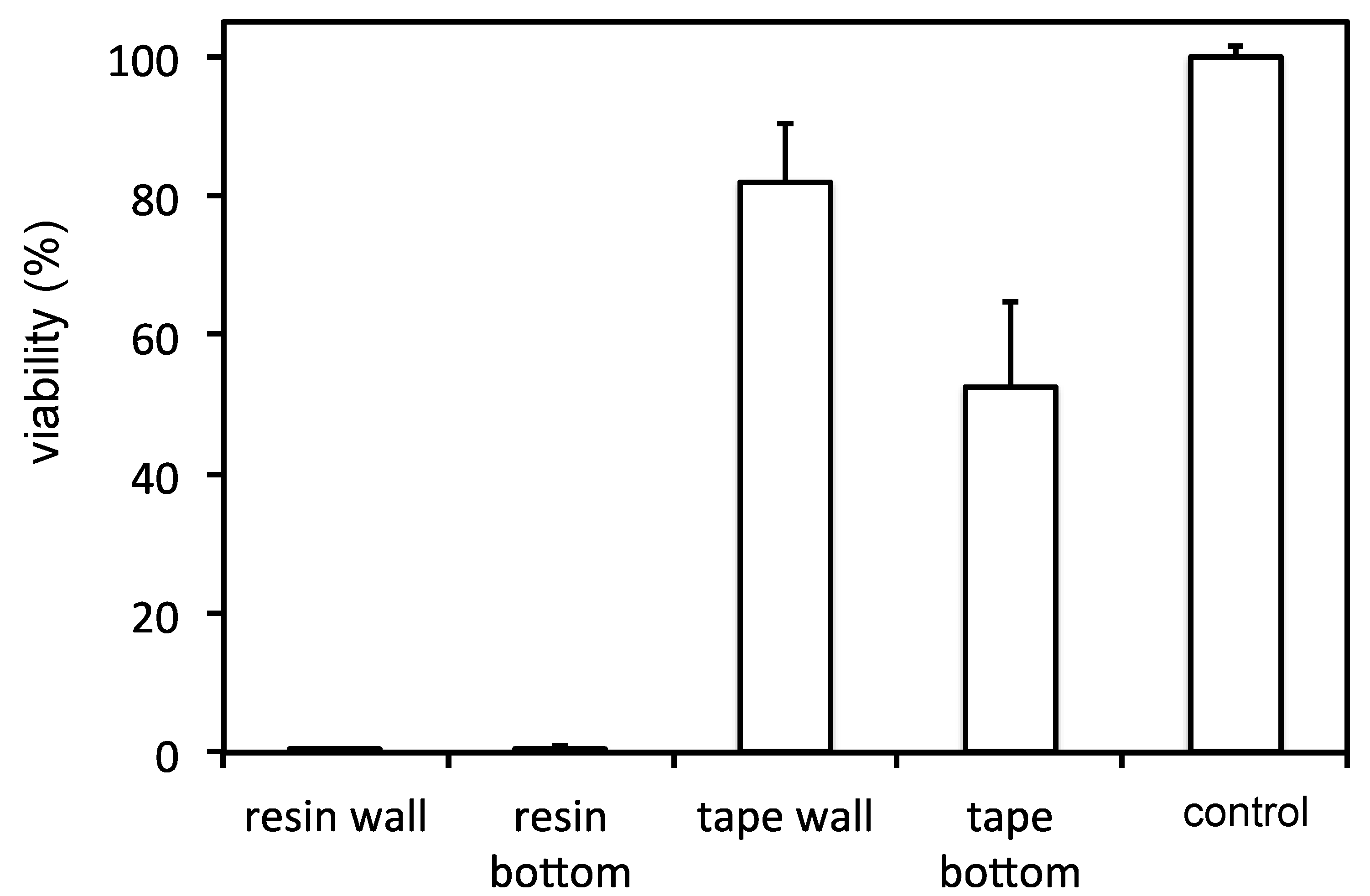
Figure 4 shows the results of the microplate reader quantification. The viability assay showed that cells died when in the presence of the cured unibody resin for 48 h. Additionally, a slow acidification of the growth medium could be detected due to the fact that the medium, which contains the pH indicator phenol red, turned orange (indicating pH of ~7) from its pink-red color at normal conditions (i.e., pH 7.4), after 48 h of incubation.
Figure 4. ULOC cell viability test assessing the toxicity of cured Miicraft resin close to cells (resin wall) and in contact with cells (resin bottom). An equivalent evaluation for cells with respect to adhesive tape was performed.
Micromachines 06 00437 g004
The adhesive tape, however, which usually is used to seal channels rather than for cell substrates, had very little effect on cell viability, especially when surrounding the wall of the growth wells. Its presence on the bottom of the well was not as well tolerated, most likely due to the texture of the adhesive coating, which compromised cell adhesion.
Accordingly, although the default resin is not biocompatible, the tape as normally used in ULOC is largely biocompatible. On the other hand, ISO 10993 biocompatible resins of similar cost as the Miicraft exist for more expensive printers that use laser illumination in the 325- and 355-nm range [30], whereas affordable Bio™ Mold (Asiga, Anaheim Hills, CA, USA) resins that can be used in contact with skin are suitable with printers using LED sources in 405- and 385-nm ranges, such as Miicraft [31].
The advantages of direct additive printing are exploited in ULOC to fabricate, in a single step, the geometries required to support the device function, but tailored to facilitate all of the other aspects of fabrication, such as material usage, printing time and assembly simplicity. Thus, the unibody design optimizes additive prototyping by minimizing material and by exploiting the planar dimension, where the printer can deliver sub-micrometric surface roughness.
The considered examples indicate the ULOC’s ability to integrate established principles and migrate classical LOC designs to a method that demands less resources and initial investment than classical microfabrication. ULOC can also integrate essential components as check-valves, the dimensions of which are compatible with manual configuration and assembly. The check-valves demonstrated here are an important contribution to ULOCs’ capabilities, which must be complemented by other valve configurations to offer the complete range of LOC possibilities.
The default material for the Miicraft printer is robust to handling common organic solvents and support chemical sensing applications. Although the default resin is not biocompatible, the tape can be used for its regular purpose in ULOC, whereas biocompatible formulations are commercially available.

4. Conclusions

These results demonstrate that consumer-grade SL 3D printers can drastically simplify custom LOC fabrication and still support complex features only accessible with advanced fabrication techniques.
The ULOC architecture makes it possible to exploit the quality of the surface finish granted by this fabrication technique, thus simplifying assembly and minimizing materials and prototyping time. These aspects have been demonstrated at convenient development costs of less than 1 US$ per prototype and for total fabrication times, including printing and assembly, under 30 min [10].
ULOC devices are a cost-effective, fast prototyping alternative to create essential functionalities for practical sample handling and readout, also providing a hybrid fabrication concept in which it is natural to blend 3D mechanical design with classical planar configurations, which was illustrated here with the integration of check-valves with a robust performance up to 70 psi.
The default resin used in ULOC fabrication is chemically robust, but not biocompatible, while the tape as used in ULOC is predominantly biocompatible.

Acknowledgments

This work has been supported by grants to Daniel Filippini, from the Swedish Research Council (Vetenskapsrådet) and the Carl Tryggers Foundation.

Author Contributions

The authors contributed equally to this work.

Conflicts of Interest

The authors declare no conflict of interest.

References

  1. Mitra, S.K.; Chakraborty, S. Microfluidics and Nanofluidics Handbook: Fabrication, Implementation, and Applications; CRC Press and Taylor & Francis Group: Boca Raton, FL, USA, 2012. [Google Scholar]
  2. Love, J.; Wolfe, D.; Jacobs, H.; Whitesides, G. Microscope projection photolithography for rapid prototyping of masters with micron-scale features for use in soft lithography. Langmuir 2001, 17, 6005–6012. [Google Scholar] [CrossRef]
  3. Sun, C.; Fang, N.; Wu, D.; Zhang, X. Projection micro-stereolithography using digital micro-mirror dynamic mask. Sens. Actuators A Phys. 2005, 121, 113–120. [Google Scholar] [CrossRef]
  4. Preechaburana, P.; Filippini, D. Fabrication of monolithic 3D micro-systems. Lab Chip 2011, 11, 288–295. [Google Scholar] [CrossRef] [PubMed]
  5. McDonald, J.; Chabiny, M.; Metallo, S.; Anderson, J.; Stroock, A.; Whitesides, G. Prototyping of microfluidic devices in poly(dimethylsiloxane) using solid-object printing. Anal. Chem. 2002, 74, 1537–1545. [Google Scholar] [CrossRef] [PubMed]
  6. Kitson, P.; Rosnes, M.; Sans, V.; Dragone, V.; Cronin, L. Configurable 3D-printed millifluidic and microfluidic “lab on a chip” reactionware devices. Lab Chip 2012, 12, 3267–3271. [Google Scholar] [CrossRef] [PubMed]
  7. Evans, B. Practical 3D Printers: The Science and Art of 3D Printing; Apress and Springer Science+Business Media: New York, NY, USA, 2012. [Google Scholar]
  8. Shallan, A.I.; Smejkal, P.; Corban, M.; Guijt, R.M.; Breadmore, M.C. Cost-effective three-dimensional printing of visibly transparent microchips within minutes. Anal. Chem. 2014, 86, 3124–3130. [Google Scholar] [CrossRef] [PubMed]
  9. Comina, G.; Suska, A.; Filippini, D. PDMS lab-on-a-chip fabrication using 3D printed templates. Lab Chip 2014, 14, 424–430. [Google Scholar] [CrossRef] [PubMed]
  10. Comina, G.; Suska, A.; Filippini, D. Low cost lab-on-a-chip prototyping with a consumer grade 3D printer. Lab Chip 2014, 14, 2978–2982. [Google Scholar] [CrossRef] [PubMed]
  11. MiiCraft®,MiiCraft 3D Printer. Available online: http://www.miicraft.com/products/ (accessed on 23 December 2014).
  12. Wong, R.; Harley, I.; Tse, Y. Lateral Flow Immunoassay; Humana Press and Springer Science+Business Media: New York, NY, USA, 2009. [Google Scholar]
  13. Lee, N.; Yang, Y.; Kim, Y.; Park, S. Microfluidic immunoassay platform using antbody-immobilized glas beads and its appliacation for the detection of Escherichia coli O157:H7. Bull. Korean Chem. Soc. 2006, 27, 479–484. [Google Scholar] [CrossRef]
  14. Au, A.K.; Lai, H.; Utela, B.R.; Folch, A. Microvalves and micropumps for BioMEMS. Micromachines 2011, 2, 179–220. [Google Scholar] [CrossRef]
  15. Yang, B.; Lin, Q. Planar micro-check valves exploiting large polymer compliance. Sens. Actuators A Phys. 2007, 134, 186–193. [Google Scholar] [CrossRef]
  16. Mosadegh, B.; Kuo, C.; Tung, Y.; Torisawa, Y.; Takayama, S. A monolithic passive check-valve for systematic control of temporal actuation in microfluidic devices. In Proceedings of the Twelfth International Conference on Miniaturized Systems for Chemistry and Life Sciences, San Diego, CA, USA, 12–16 October 2008; pp. 826–828.
  17. Suska, A.; Comina, G.; Filippini, D. Unibody three channels injector with integrated manual pumps. In Proceedings of the MFHS 2014–2nd International Conference on MicroFluidic Handling Systems, Freiburg, Germany, 8–10 October 2014; pp. 146–149.
  18. Suska, A.; Ibañez, A.B.; Lundström, I.; Berghard, A. G protein-coupled receptor mediated trimethylamine sensing. Biosens. Bioelectron. 2009, 25, 715–720. [Google Scholar] [CrossRef] [PubMed]
  19. Czekanska, E.M. Assessment of cell proliferation with resazurin-based fluorescent dye. Methods Mol. Biol. 2011, 740, 27–32. [Google Scholar] [PubMed]
  20. 3D Printer Guide. Available online: http://www.3dhubs.com/best-3d-printer-guide (accessed on 23 December 2014).
  21. Yuen, J.; Benzie, I. Hydrogen peroxide in urine as a potential biomarker of whole body oxidative stress. Free Radic. Res. 2003, 37, 1209–1213. [Google Scholar] [CrossRef] [PubMed]
  22. Halliwell, B. Oxidative stress and cancer: Have we moved forward? Biochem. J. 2007, 401, 1–11. [Google Scholar] [CrossRef] [PubMed]
  23. Singh, N.; Dhalla, A.K.; Seneviratne, C.; Singal, P.K. Oxidative stress and heart failure. Mol. Cell. Biochem. 1995, 147, 77–81. [Google Scholar] [CrossRef] [PubMed]
  24. Zimmermann, M.; Hunziker, P.; Delamarche, E. Autonomous capillary system for one-step immunoassays. Biomed. Microdevices 2009, 11, 1–8. [Google Scholar] [CrossRef] [PubMed]
  25. Martinez, A.W.; Phillips, S.T.; Whitesides, G.M. Three-dimensional microfluidic devices fabricated in layered paper and tape. Proc. Natl. Acad. Sci. USA 2008, 105, 19606–19611. [Google Scholar] [CrossRef] [PubMed]
  26. Carrilho, E.; Martinez, A.W.; Whitesides, G.M. Understanding wax printing: A simple micropatterning process for paper-based microfluidics. Anal. Chem. 2009, 81, 7091–7095. [Google Scholar] [CrossRef] [PubMed]
  27. Nguyen, N.; Wu, Z. Micromixers—A review. J. Micromech. Microeng. 2005, 15, R1–R16. [Google Scholar] [CrossRef]
  28. Preechaburana, P.; Collado Gonzalez, M.; Suska, A.; Filippini, D. Surface plasmon resonance chemical sensing on cell phones. Angew. Chem. 2012, 52, 11585–11588. [Google Scholar] [CrossRef]
  29. Iwai, K.; Shih, K.S.; Lin, X.; Brubaker, T.A.; Sochol, R.D.; Lin, L. Finger-powered microfluidic systems using multilayer soft lithography and injection molding processes. Lab Chip 2014, 14, 3790–3799. [Google Scholar] [CrossRef] [PubMed]
  30. Somos® WaterShed XC 11122: The Difference Is Clear. Available online: http://www.dsm.com/products/somos/en_US/offerings/offerings-somos-water-shed.html (accessed on 4 February 2015).
  31. ASIGA. Material World. Available online: https://www.asiga.com/products/materials/ (accessed on 4 February 2015).

