
Design and Performance Study for Electrothermally Deep-Sea Drive Microunits Using a Paraffin Phase Change Material

 , ,
, ,
Abstract
:1. Introduction
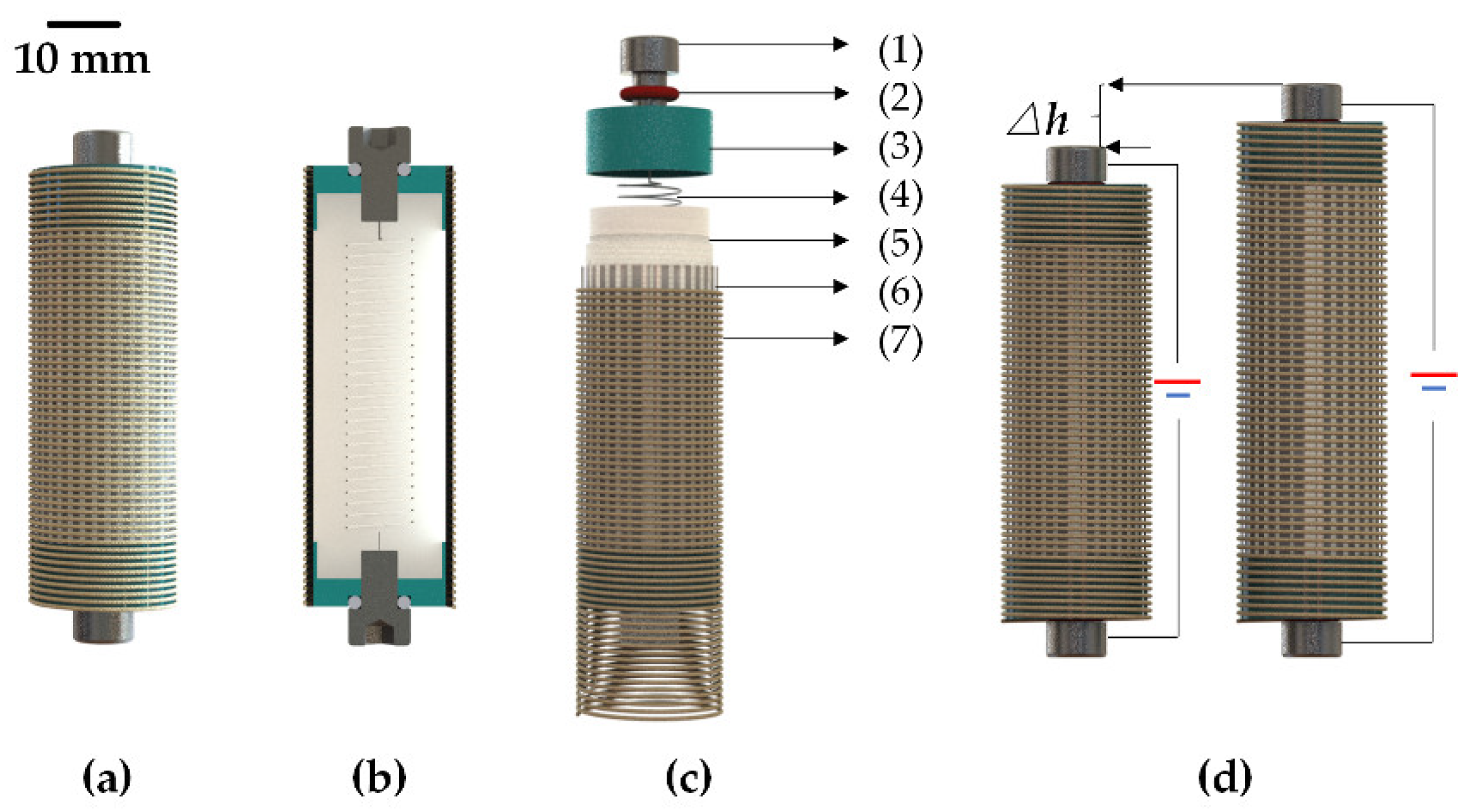
2. Design and Fabrication
2.1. Design
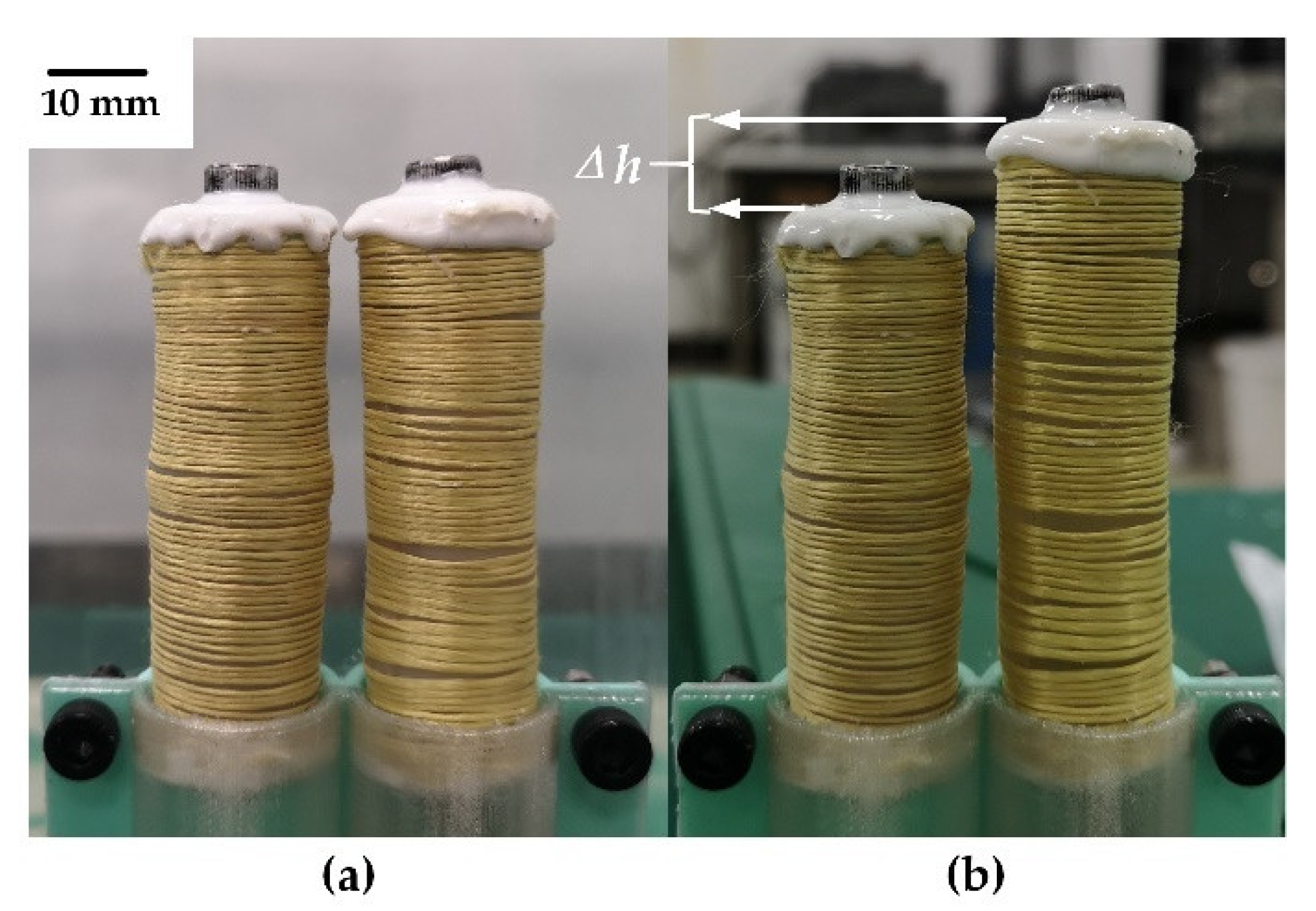
2.2. Fabrication
3. Experimental Procedures
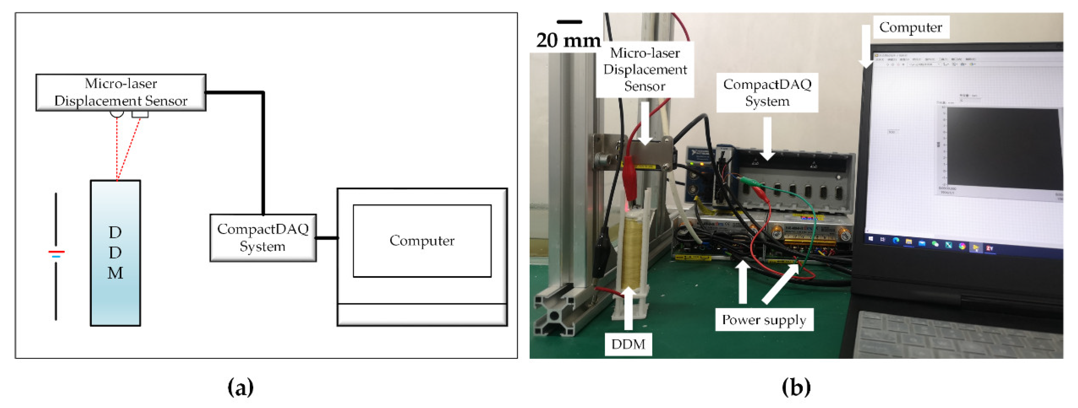
3.1. Displacement Characteristics Test
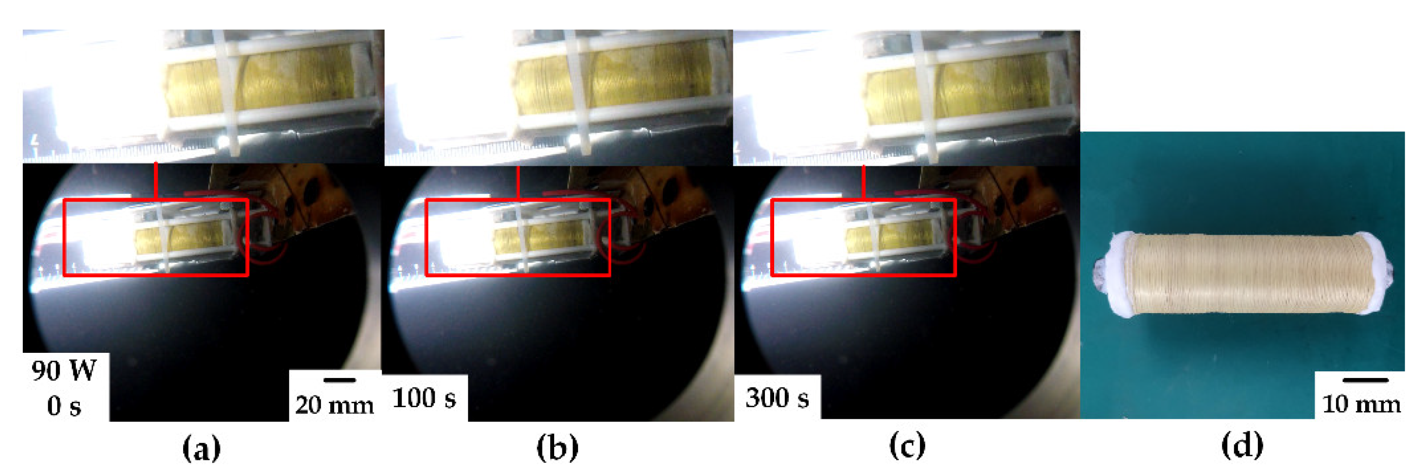
3.1.1. Air Displacement Characteristics Test
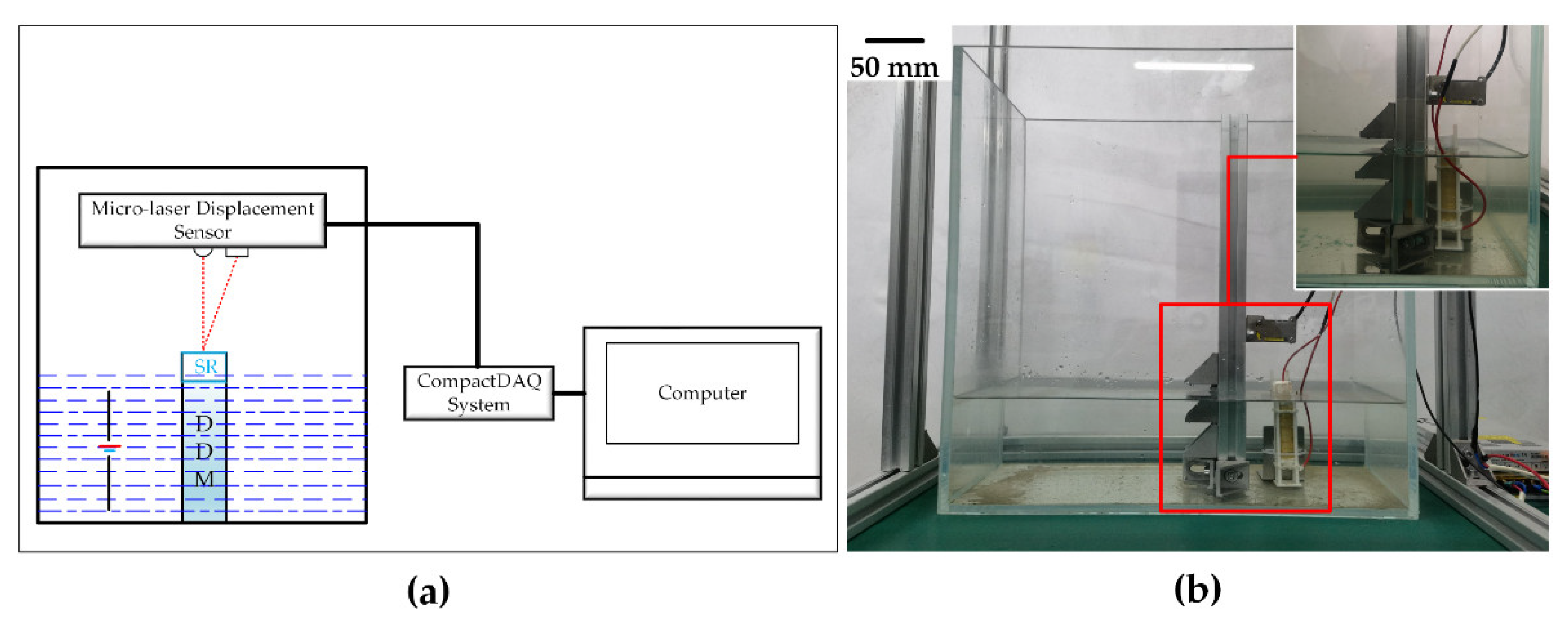
3.1.2. Underwater Displacement Characteristics Test
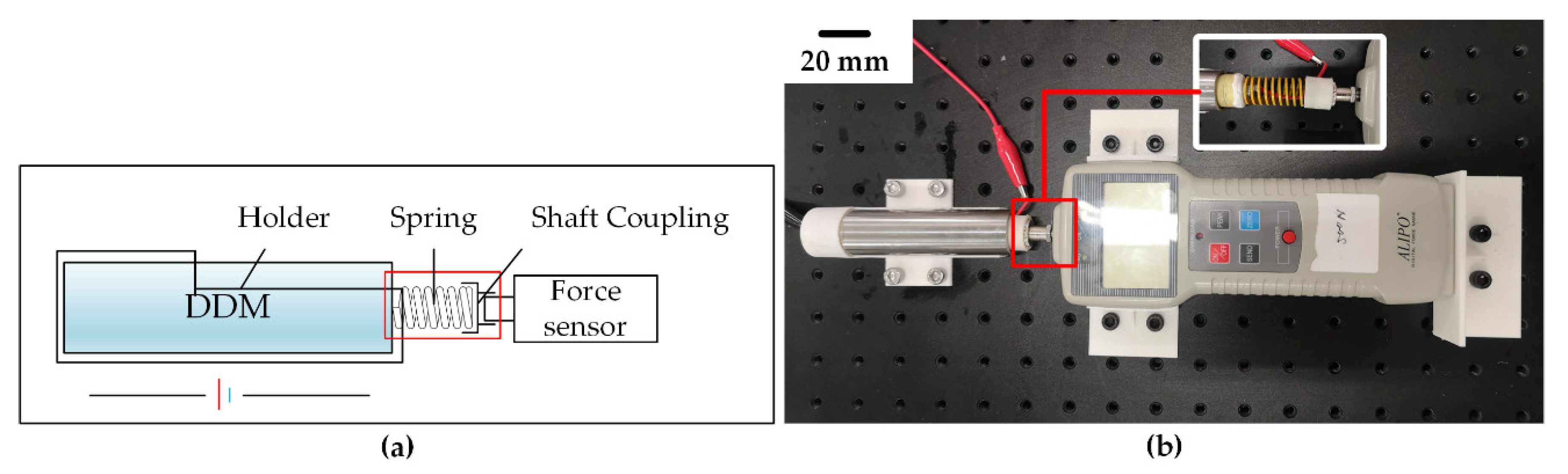
3.2. Force Characteristics Test
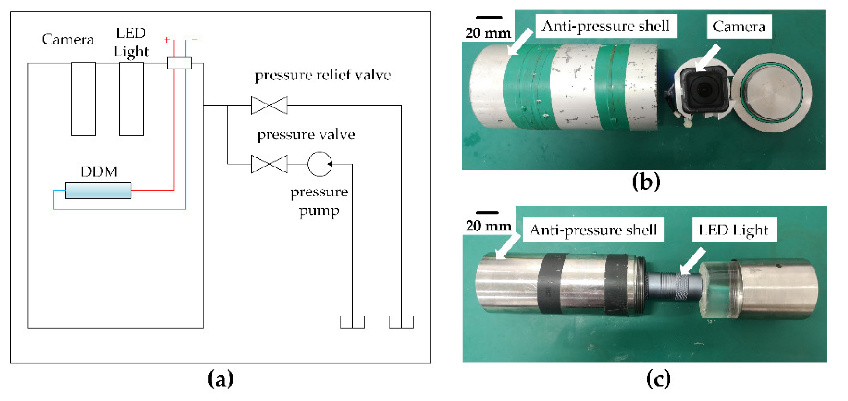
3.3. Anti-Pressure Characteristics Test
4. Results
4.1. Displacement Characteristics
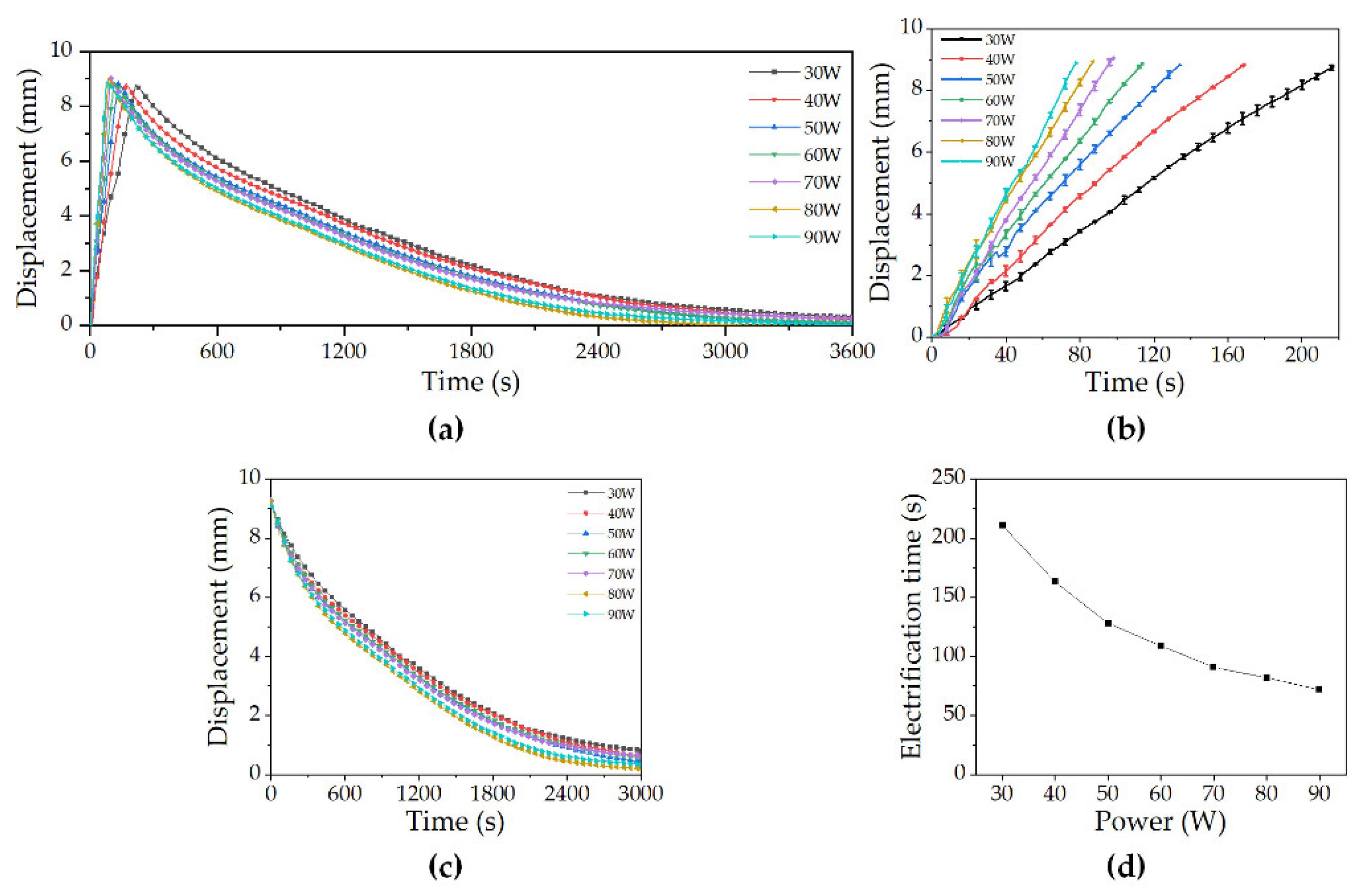
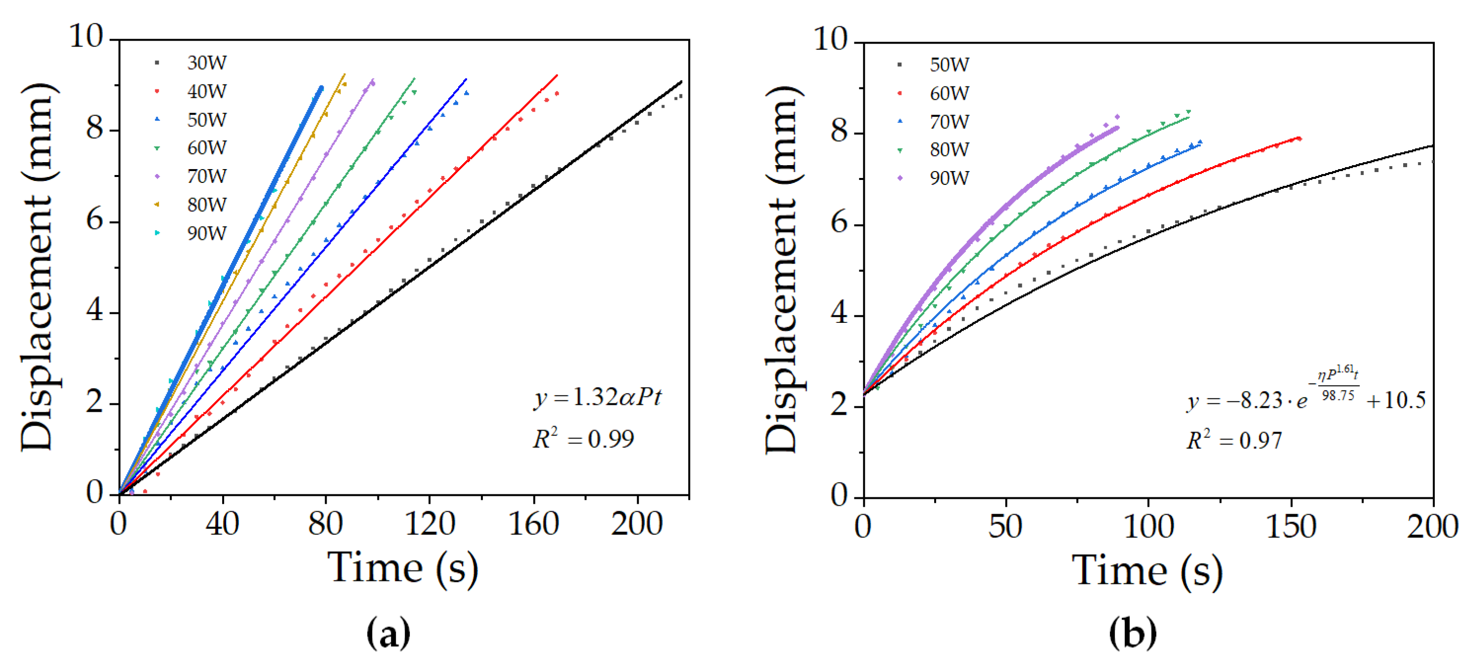
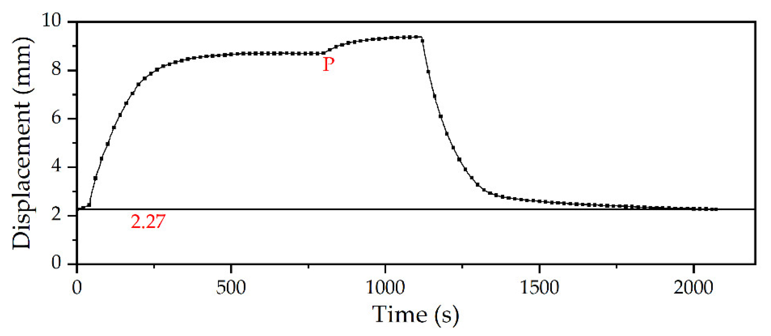
4.1.1. Air Displacement Characteristics
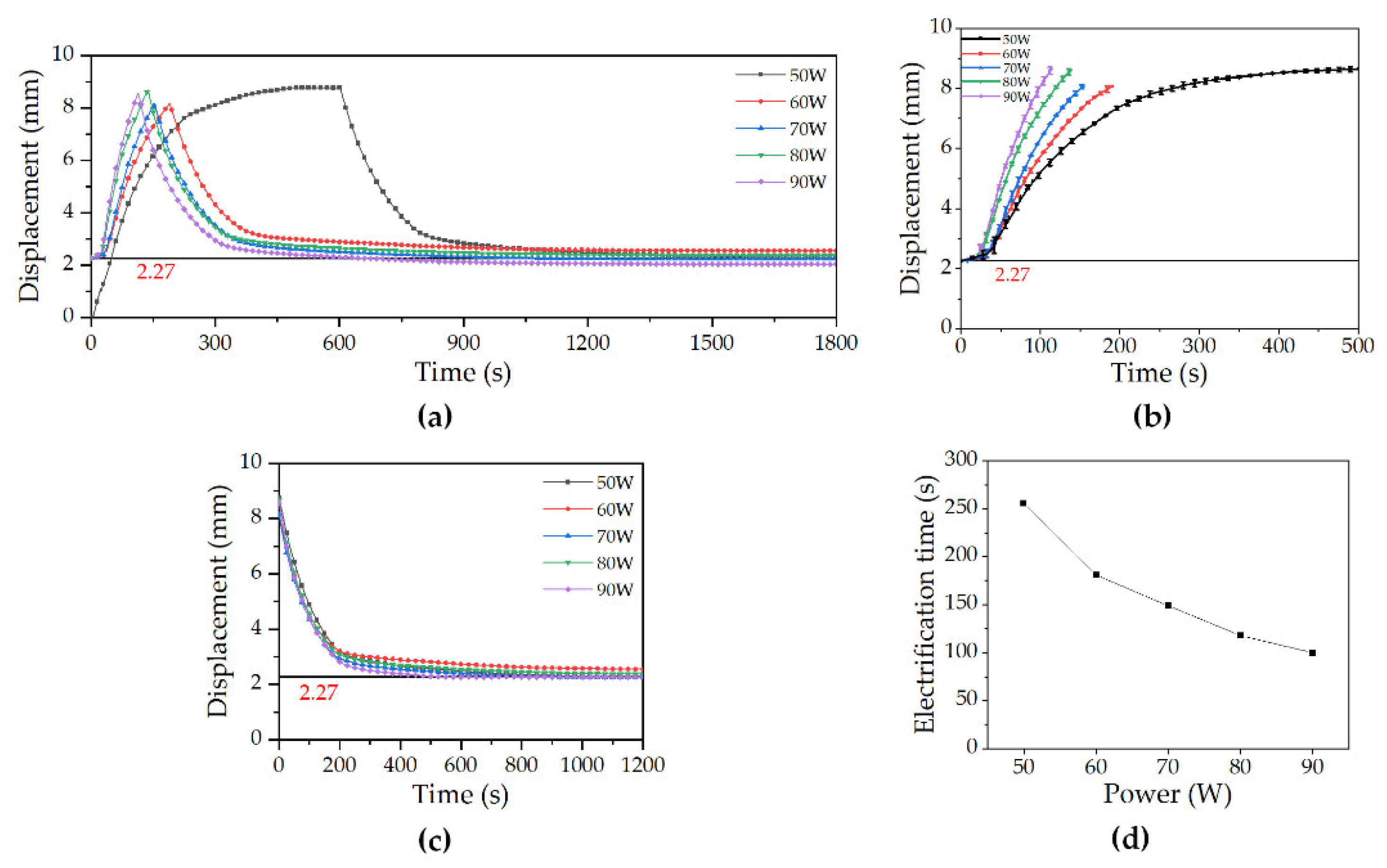
4.1.2. Underwater Displacement Characteristics
4.2. Force Characteristics
4.3. Anti-Pressure Characteristics
4.4. Displacement Characteristics Curve Fitting Analysis
5. Discussion
5.1. Air Displacement Characterization
5.2. Underwater Displacement Characterization
5.3. Force Characterization
6. Conclusions
Supplementary Materials
Author Contributions
Funding
Conflicts of Interest
References
- Wang, K.; Shen, Y.; Yang, Y.; Gan, X.; Liu, G.; Hu, K.; Li, Y.; Gao, Z.; Zhu, L.; Yan, G.; et al. Morphology and genome of a snailfish from the Mariana Trench provide insights into deep-sea adaptation. Nat. Ecol. Evol. 2019, 3, 823–833. [Google Scholar] [CrossRef] [PubMed] [Green Version]
- Petersen, S.; Auml, K.; Tschell, A.; Augustin, N.; Jamieson, J.; Hein, J.R.; Hannington, M.D. News from the seabed—Geological characteristics and resource potential of deep-sea mineral resources. Mar. Policy 2016, 70, 175–187. [Google Scholar] [CrossRef]
- Roberto, D.; Batista, C.J.; Cinzia, C.; Gianfranco, D.; Bella, G.; Cristina, G.; Gooday, A.J.; Nikolaos, L.; Marco, L.G.; Caterina, M. Deep-Sea Biodiversity in the Mediterranean Sea: The Known, the Unknown, and the Unknowable. PLoS ONE 2010, 5, e11832. [Google Scholar]
- Kunzig, R. Deep-Sea Biology: Living with the Endless Frontier. Science 2003, 302, 991. [Google Scholar] [CrossRef] [Green Version]
- McPhail, S. Autosub6000: A Deep Diving Long Range AUV. J. Bionics Eng. 2009, 6, 55–62. [Google Scholar] [CrossRef] [Green Version]
- Liu, Y.; Wu, D.; Li, D.; Deng, Y. Applications and Research Progress of Hydraulic Technology in Deep Sea. J. Mech. Eng. G 2018, 54, 14–23. [Google Scholar] [CrossRef]
- Cao, X.; Wei, C.; Zhao, S.; Cao, H. Study on the Change Law of Oil Density Characteristics Based on Deep Sea Environment Model. Lubr. Eng. 2020, 45, 41–46. [Google Scholar]
- Song, L.; Liu, Z.; Hu, J.; Li, X.; Du, C.; Li, Y.; Pan, Y. Stress Corrosion Cracking of 2205 Duplex Stainless Steel with Simulated Welding Microstructures in Simulated Sea Environment at Different Depths. J. Mater. Eng. Perform. 2020, 29, 5476–5489. [Google Scholar] [CrossRef]
- Umapathy, A.; Babu, S.M.; Vedachalam, N.; Venkatesan, K.; Kumar, N.K.S.; Gopakumar, K.; Ramadass, G.A.; Atmanand, M.A. Influence of Deep-Sea Ambient Conditions in the Performance of Pressure-Compensated Induction Motors. Mar. Technol. Soc. J. 2019, 53, 67–73. [Google Scholar] [CrossRef]
- Cao, X.; Tuo, S.; Zhang, C.; Moussa, A.D.; Lei, Z. Design and Modeling of Oceanographic Environment Adaptive Variable Pumps. IEEE Access 2020, 8, 73015–73026. [Google Scholar] [CrossRef]
- Li, L.; Wu, J. Deformation and leakage mechanisms at hydraulic clearance fit in deep-sea extreme environment. Phys. Fluids 2020, 32, 67115. [Google Scholar] [CrossRef]
- Nie, S.; Guo, M.; Yin, F.; Ji, H.; Ma, Z.; Hu, Z.; Zhou, X. Research on fluid-structure interaction for piston/cylinder tribopair of seawater hydraulic axial piston pump in deep-sea environment. Ocean Eng. 2021, 219, 108222. [Google Scholar] [CrossRef]
- Gill, J.J. Manufacturing issues of thin film NiTi microwrapper. Sens. Actuators A Phys. 2001, 148–156. [Google Scholar] [CrossRef]
- Ikeda, T.; Nakano, M.; Yu, Y.L.; Tsutsumi, O.; Kanazawa, A. Anisotropic Bending and Unbending Behavior of Azobenzene Liquid-Crystalline Gels by Light Exposure. Adv. Mater. 2003, 15, 201–205. [Google Scholar] [CrossRef]
- Ma, C.; Lu, W.; Yang, X.; He, J.; Le, X.; Wang, L.; Zhang, J.; Serpe, M.J.; Huang, Y.; Chen, T. Bioinspired Anisotropic Hydrogel Actuators with On-Off Switchable and Color-Tunable Fluorescence Behaviors. Adv. Funct. Mater. 2018, 28, 1704568. [Google Scholar] [CrossRef]
- Ogden, S.; Klintberg, L.; Thornell, G.; Hjort, K.; Bodén, R. Review on miniaturized paraffin phase change actuators, valves, and pumps. Microfluid Nanofluid 2014, 17, 53–71. [Google Scholar] [CrossRef] [Green Version]
- Zoller, P.; Walsh, D. Standard Pressure Volume Temperature Data for Polymers; CRC Press: Boca Raton, FL, USA, 1995. [Google Scholar]
- Wang, M.; Yu, G.; Zhang, X.; Zhang, T.; Yu, B.; Sun, D. Numerical investigation of melting of waxy crude oil in an oil tank. Appl. Therm. Eng. 2017, 115, 81–90. [Google Scholar] [CrossRef] [Green Version]
- Abdulrahman, R.S.; Ibrahim, F.A.; Dakhil, S.F. Development of paraffin wax as phase change material based latent heat storage in heat exchanger. Appl. Therm. Eng. 2019, 150, 193–199. [Google Scholar] [CrossRef]
- Mallya, N.; Haussener, S. Buoyancy-driven melting and solidification heat transfer analysis in encapsulated phase change materials. Int. J. Heat Mass Tran. 2021, 164, 120525. [Google Scholar] [CrossRef]
- Srivastava, S.P.; Handoo, J.; Agrawal, K.M.; Joshi, G.C. Phase-transition studies in n-alkanes and petroleum-related waxes—A review. J. Phys. Chem. Solids 1993, 54, 639–670. [Google Scholar] [CrossRef]
- Zhang, S.; Wang, L.; Nie, C.; He, Y.; Zhang, X.; Yan, X. Development of a large load space- used paraffin actuator. J. Beijing Univ. Aeronaut. Astronaut. 2017, 43, 1038–1044. [Google Scholar]
- Mann, A.; Germann, T.; Ruiter, M.; Groche, P. The challenge of upscaling paraffin wax actuators. Mater. Design 2020, 190, 108580. [Google Scholar] [CrossRef]
- Sharma, G.; Svensson, S.; Ogden, S.; Klintberg, L.; Hjort, K. High-pressure stainless steel active membrane microvalves. J. Micromech. Microeng. 2011, 21, 075010. [Google Scholar] [CrossRef]
- Jin, Z.; Qiu, C.; Jiang, C.; Wu, J.; Qian, J. Effect of valve core shapes on cavitation flow through a sleeve regulating valve. J. Zhejiang Univ. A Sci. 2020, 21, 1–14. [Google Scholar] [CrossRef]
- Qian, J.; Chen, M.; Liu, X.; Jin, Z. A numerical investigation of the flow of nanofluids through a micro Tesla valve. J. Zhejiang Univ. A Sci. 2019, 20, 50–60. [Google Scholar] [CrossRef]
- Swanson, T.D. MEMS Device for Spacecraft Thermal Control Applications. U.S. Patent 6,538,796, 25 March 2003. [Google Scholar]
- Lee, J.S.; Lucyszyn, S. Design and pressure analysis for bulk-micromachined electrothermal hydraulic microactuators using a PCM. Sens. Actuators A Phys. 2007, 133, 294–300. [Google Scholar] [CrossRef]
- Ayers, J.A.; Tang, W.C.; Chen, Z. Paraffin Actuated Micromirror for Endoscopic OCT. In Proceedings of the Asme Frontiers in Biomedical Devices Conference, Irvine, CA, USA, 8–9 June 2009. [Google Scholar]
- Hou, J.; Zou, W.; Li, Z.; Gong, Y.; Burnashev, V.; Ning, D. Development and Experiments of an Electrothermal Driven Deep-Sea Buoyancy Control Module. Micromachines 2020, 11, 1017. [Google Scholar] [CrossRef]
- Huang, H.; Guo, Y.; Zhao, X.; Yuan, Z.; Leng, J.; Wei, Y. A film-type pressure self-adaptive watertight junction box in deep-sea equipment. Ocean Eng. 2019, 189, 106387. [Google Scholar] [CrossRef]
- Li, G.; Li, M.; Li, N.; Zhou, E. The performance study on the Kevlar twaron fabric. New Chem. Mater. 2011, 39, 51–53. [Google Scholar]


| Parameter | Symbol | Values |
|---|---|---|
| Mass of prototype | MDDM | 12,908.49 mm3 |
| Mass of filled paraffin PCM | MPCM | 11.62 g |
| Volume of paraffin PCM | VPCM | 30 g |
| Height of prototype | h | 70 mm |
| Radius of prototype | r | 10 mm |
| Thickness of SR shell | b | 1 mm |
| Displacement | Δh | 8.62 mm |
| Resistance of heating wire | R | 9 Ω |
| Volume expansion rate of PCM | α | 17% |
| Test No. | Test Environment | Environment Temperature (°C) | Environment Pressure (MPa) | Power (W) |
|---|---|---|---|---|
| 1 | Air | 18 | 0.1 | 30, 40, 50, 60, 70, 80, 90 |
| 2 | Water | 6 | 0.1 | 50, 60, 70, 80, 90 |
| 3 | Air | 18 | 0.1 | / |
| 4 | Water | 17.8 | 110 | 50, 60, 70, 80, 90 |
| Test Environment | Power (W) | Electrification Time (s) | Percentage Error (%) |
|---|---|---|---|
| Air | 90 | 30 50 70 | −0.40% 5.51% 2.64% |
| Underwater | 90 | 35 55 65 | 1.25% 0.86% −0.15% |
Publisher’s Note: MDPI stays neutral with regard to jurisdictional claims in published maps and institutional affiliations. |
© 2021 by the authors. Licensee MDPI, Basel, Switzerland. This article is an open access article distributed under the terms and conditions of the Creative Commons Attribution (CC BY) license (https://creativecommons.org/licenses/by/4.0/).
Share and Cite
Ning, D.; Li, Z.; Liang, G.; Wang, Q.; Zou, W.; Gong, Y.; Hou, J. Design and Performance Study for Electrothermally Deep-Sea Drive Microunits Using a Paraffin Phase Change Material. Micromachines 2021, 12, 415. https://doi.org/10.3390/mi12040415
Ning D, Li Z, Liang G, Wang Q, Zou W, Gong Y, Hou J. Design and Performance Study for Electrothermally Deep-Sea Drive Microunits Using a Paraffin Phase Change Material. Micromachines. 2021; 12(4):415. https://doi.org/10.3390/mi12040415
Chicago/Turabian StyleNing, Dayong, Zihao Li, Gangda Liang, Qibo Wang, Weifeng Zou, Yongjun Gong, and Jiaoyi Hou. 2021. "Design and Performance Study for Electrothermally Deep-Sea Drive Microunits Using a Paraffin Phase Change Material" Micromachines 12, no. 4: 415. https://doi.org/10.3390/mi12040415