Mechanical Properties of a Thermally-aged Cast Duplex Stainless Steel by in Situ Tensile Test at the Service Temperature


School of Materials Science and Engineering, Tsinghua University, Beijing 100084, China
*
Author to whom correspondence should be addressed.
Metals 2019, 9(3), 317; https://doi.org/10.3390/met9030317
Submission received: 31 January 2019
/
Revised: 7 March 2019
/
Accepted: 8 March 2019
/
Published: 12 March 2019
Abstract
:Z3CN20.09M cast duplex stainless steel (CDSS) has been used for primary coolant water pipes in pressurized water reactors due to its excellent mechanical properties. Such pipes operate at an elevated service temperature (~320 °C) and experience issues of thermal aging embrittlement. In situ tensile tests were conducted to investigate the deformation mechanisms of Z3CN20.09M CDSS after long-term thermal aging at 475 °C for up to 2000 h in both optical microscope and scanning electron microscope at 320 °C. For the 320 °C tests, the tensile stress and other mechanical properties, e.g. the yield stress and the ultimate tensile strength, increase during the thermal aging process and recover to almost the same level as the unaged condition after annealing heat-treatment, which is caused by the formation and dissolution of precipitation during aging and anneal heat-treatment, respectively. For the slip mechanism, straight slip lines form first in the austenite phase. When these slip lines reach the austenite/ferrite interface, three kinds of slip systems are found in the ferrite phase. During the fracture process, the austenite phase is torn apart and the ferrite phase shows a significant elongation. The role of the ferrite phase is to hold the austenite matrix, thus increasing the tensile strength of this steel.
1. Introduction
Compared with ferritic and austenitic stainless steels, cast duplex stainless steels consisting of ferrite and austenite are unique engineering materials widely applied in chemical, petrochemical, nuclear and other industries because of their excellent combination of mechanical properties and corrosion resistance [1,2,3]. One use for CDSS is in coolant water pipes in the pressurized water reactor (PWR) which are designed for at least a 40-year service life and to work in service temperatures ranging from 288 °C to 327 °C [4]. Hence, such pipes experience problems of thermal aging embrittlement during service that cause degradation in mechanical properties [5,6,7,8,9,10,11,12,13,14,15]. It has been reported that the thermal aging embrittlement in CDSS was caused by the precipitation that formed in the ferrite phase after long-term thermal aging, e.g. the G-phase precipitates and the spinodal decomposition during which the ferrite phase decomposes into a Fe-rich α-phase and a Cr-rich α’-phase [10,11,13,14,15]. Many researchers have found that the mechanical properties of CDSS are strongly dependent on the strength of each individual phase [16,17] and their microstructures, e.g. the volume fraction and the morphology of the ferrite phase, have meaningful influence on the fracture toughness, thermal aging embrittlement, high-temperature ductility, impact properties and corrosion resistance of duplex stainless steel [18,19,20,21,22,23,24].
In addition to the mechanical properties, some researchers have also investigated the deformation behaviors and damage mechanisms of CDSS. Cingara [25] found that in two types of ferritic-martensitic duplex stainless steels, the voids nucleation occurs through either cracking in the martensite phase, the separation of adjacent martensite regions, or decohesion at the ferrite/martensite interface. Serre [26] used an atomic force microscopy (AFM) technique to study the slip systems in an austenitic-ferritic duplex stainless steel and classified several different slip bands in ferrite grains according to their morphology.
There are two main reasons to study the slip deformation mechanisms. First of all, due to the service conditions of relatively high-frequency impact force with high temperature for the studied steel, it is necessary to unveil the details of slip deformation mechanisms, which would be beneficial to a deep understanding of the relationship between microstructures and mechanical properties. In addition, the study of slip deformation mechanisms can help to pinpoint the deformation behaviors in local regions where micro-cracks form then start propagation, an opportunity which is not available in typical macro tests on CDSS. Secondly, the 3D numerical simulation method shows an advantage over experiments, not only in its costs but also in revealing some important phenomena that cannot be directly observed by experiments. The understanding of slip deformation mechanisms can be used as benchmarks for further numerical simulations. To investigate the slip deformation with time, many in situ or quasi in situ tests have been conducted using CDSS. Guo [4] used an in situ scanning electron microscopy (SEM) technique to study the mechanical properties and slip deformation of an unaged CDSS at various temperatures, ranging from 25 °C to 750 °C. Wang [27] conducted quasi in situ optical microscope (OM) tests on the thermally aged CDSS at room temperature. As the coolant water pipes suffer from the problems of both long-term thermal aging and high-temperature service, it makes a lot of sense to conduct in situ tests on the CDSS at service temperature to investigate the mechanical properties, the slip mechanisms and the damage mechanisms in CDSS.
In the present work, in situ OM and SEM tensile tests have been employed at the service temperature (320 °C) on the CDSS samples that undergo different heat-treatments. The evolution of mechanical properties and the deformation behaviors under different heat-treatment conditions are our focus in this study.
2. Materials and Methods
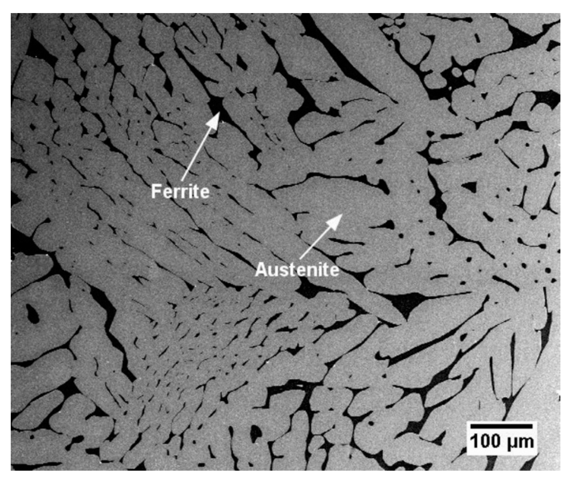
The material studied in this work was a Z3CN20.09M austenitic-ferritic cast duplex stainless steel which has been widely used for primary coolant pipes in pressurized water reactors (PWR). For CDSS, the main alloy elements are Fe, Cr, Ni, Mn, Si and C. For the widely used CF3s and CF8s, carbon contents are <0.03 wt. % and <0.08 wt. %, respectively [28]. For the steel Z3CN20.09M studied in this work, the carbon content should be less than 0.04 wt. %. Chemical compositions of this steel are listed in Table 1. The typical microstructure of the Z3CN20.09M CDSS is shown in Figure 1, in which δ ferrite shows a complex dendritic morphology with the volume fraction of about 20%. More information of this steel, such as the three-dimensional (3D) microstructure, can be found elsewhere [5]. The as received material was thermally aged at 475 °C for up to 2000 h, which is essentially equivalent to that of 45 years at the service temperature [11] according to the Arrhenius equation [29]. A part of the 2000 h-aged material was further annealed at 550 °C for 3 h to dissolve the precipitates formed during the thermal aging process [11,13,14].
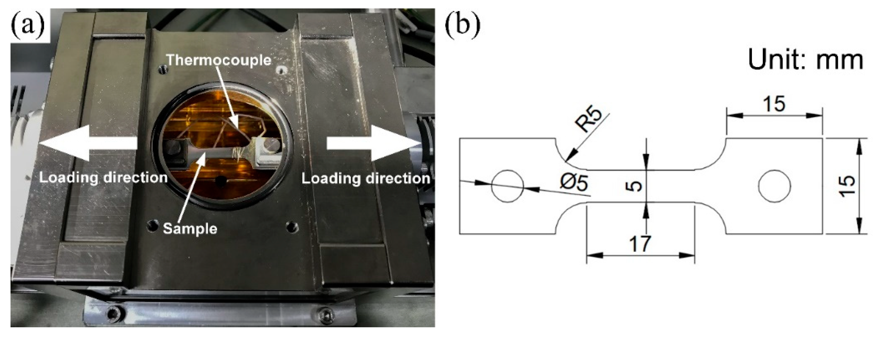
The in situ tensile tests were performed at room temperature (20 °C) and service temperature (320 °C), respectively, using a high temperature confocal scanning violet laser microscope (VL2000DX-SVF15FTC, Lasertec Corporation, Japan). Tests were conducted with a constant displacement rate of 0.25 mm·min−1 to maintain a strain rate target of ~10−4·s−1. For the high temperature tests, specimens were heated with a heating rate of 100 °C·min−1. After reaching the desired temperature, specimens were hold for 5 minutes prior to the tensile tests. In order to prevent oxidation at the elevated temperature, the tests conducted at 320 °C were carried out in an argon atmosphere with an airflow rate of 100 mLmin−1. The testing stage of VL2000DX-SVF15FTC high temperature confocal scanning violet laser microscope is shown in Figure 2a, in which the temperature was measured via a thermocouple attached to the bottom of the specimen. The dimensions of the specimen were shown in Figure 2b. Dog-bone-shaped specimens were machined from the steels with different aging conditions using electro-discharge machining (EDM) method with a thickness of about 1.2 mm. Such specimens were mechanically polished up to 2000 grit silicon carbide paper with a mirror finish, the final thickness is ~1 mm. To enhance the imaging quality and distinguish the austenite and ferrite phases, the specimens were electro-etched in a solution of 20 wt. % potassium hydroxide at ~70 °C. Electro-etching process was conducted using a 3 V direct current power supply for 15 seconds. At least three specimens were performed on each condition. It should be noted that although the confocal microscope has the advantage of high resolution, it bears the disadvantage of a shallow depth of field, which makes it difficult to capture the microstructural features during large deformation. In order to observe the tearing process and the necking deformation, several extra tests were conducted using a SS550 scanning electron microscope (SEM) equipped with a servo-hydraulic testing system (Shimadzu Corporation, Kyoto, Japan) at 320 °C.
After the tensile tests, the fractured specimens were imaged using a ZEISS Merlin field emission scanning electron microscope (SEM) (Carl Zeiss Microscopy, München, Germany). In order to characterize the microstructure evolution such as the formation of spinodal decomposition and G-phase precipitation under different conditions i.e., the 2000 h aging condition and the annealed condition. Transmission electron microscopy (TEM) tests were carried out using the specimens prepared by a twin-jet electropolishing method with a Tecnai G2 20 S-TWIN transmission electron microscope (FEI Company, Hillsboro, OR, USA).
3. Results and Discussion
3.1. Microstructural Characterization
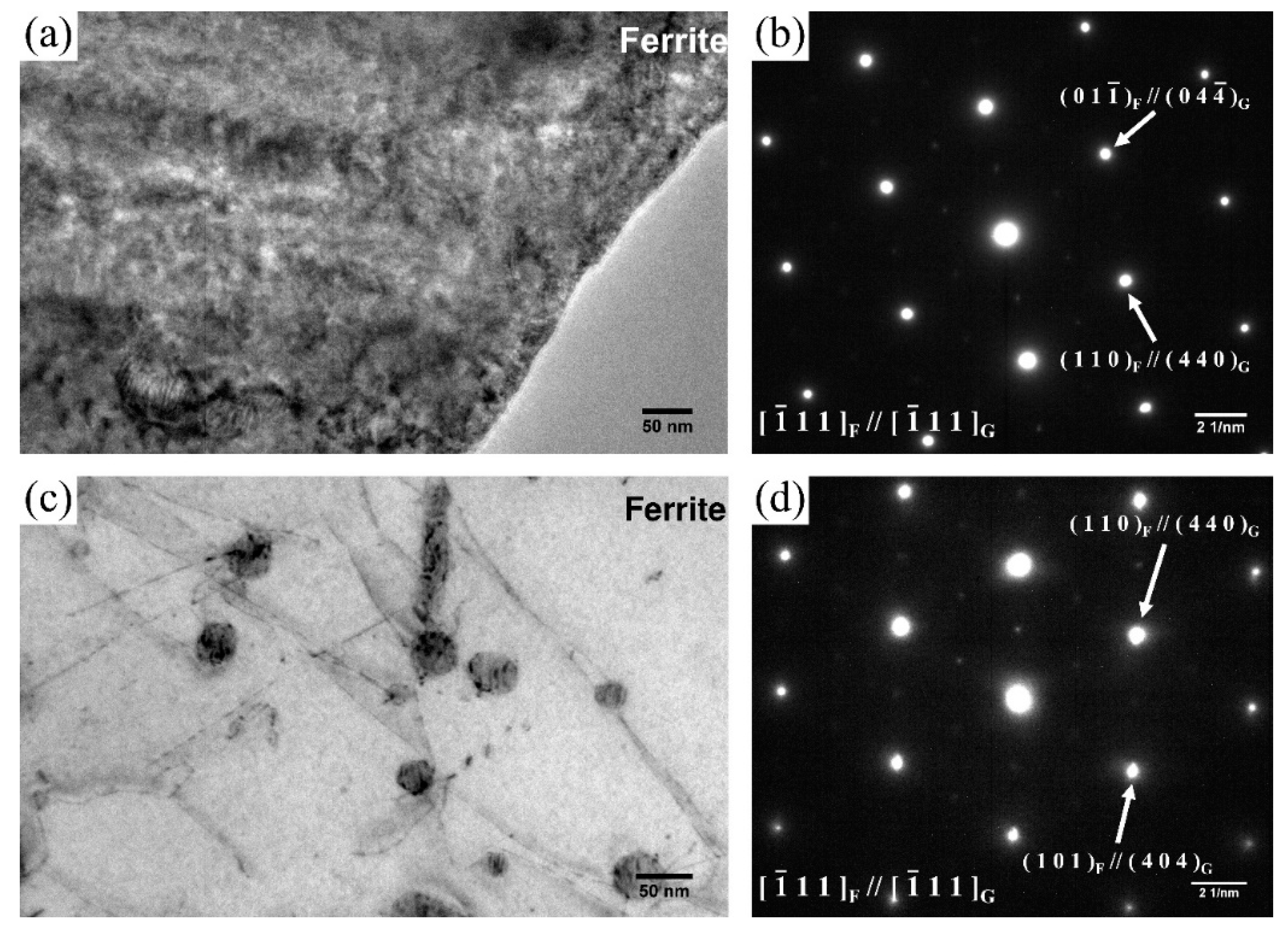
Figure 3 shows the TEM images of ferrite phase in the material under different heat-treatment conditions. Mottled structures and some small particles are found in the ferrite phase, as shown in Figure 3a. These mottled structures are caused by the spinodal decomposition. The diffraction spots shown in the electron diffraction (ED) pattern in Figure 3b prove the existence of G-phases in the 2000 h-aged specimen. Figure 3c shows the TEM image of the ferrite phase aged for 2000 h, then annealed at 550 °C for 3 h. In Figure 3c, such mottled structures as in Figure 3a disappear and the retained particles are G-phases, which can be verified by the ED result in Figure 3d. Therefore, it can be concluded that after the long-term thermal aging process, both the spinodal decomposition and G-phase precipitates form in the ferrite phase. Then the spinodal decomposition can be dissolved by further annealing, with only the G-phases left. Based on the ED pattern shown in Figure 3b,d, the G-phase shows a face-centered cubic structure with the lattice parameter almost four times of the ferrite matrix. A similar result for the G-phase was also found by other researchers [14].
3.2. Stress–Strain Behavior
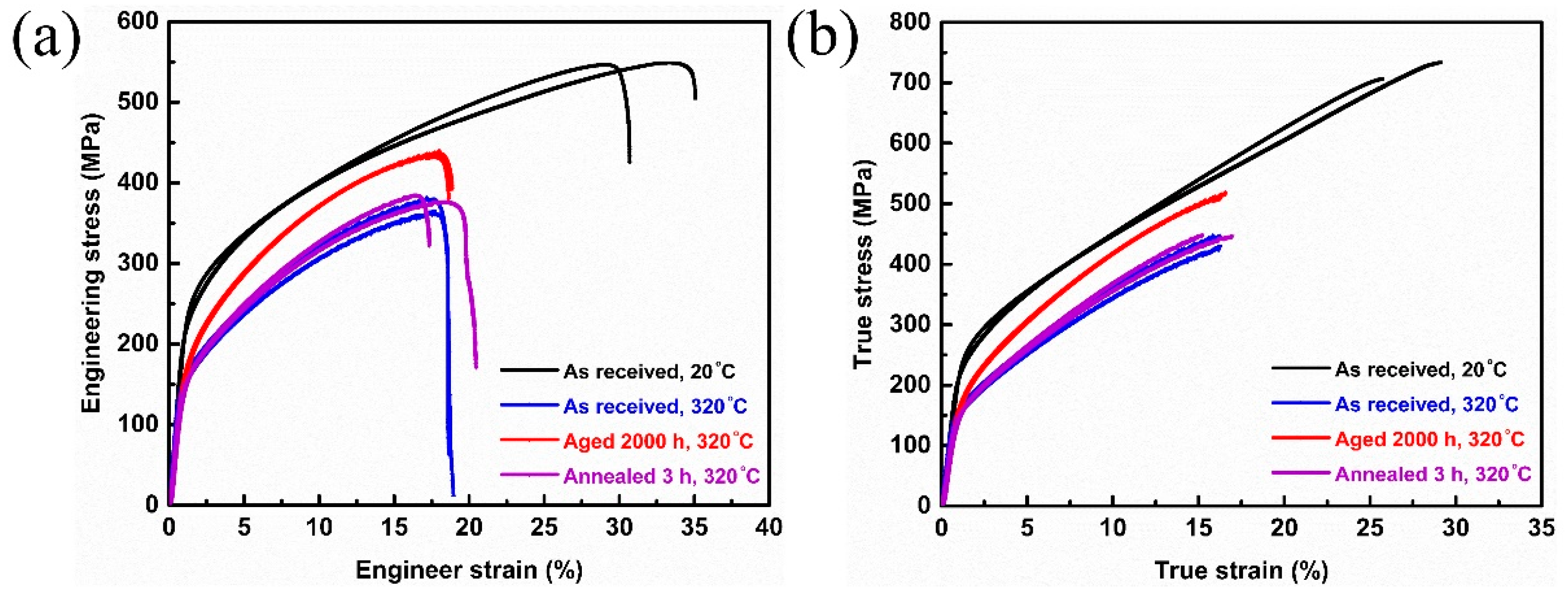
Figure 4a,b show the engineering stress–strain curves and true stress-strain curves obtained from the in situ tensile tests, respectively. Figure 4 shows four kinds of different test conditions: “as received, 20 °C” represents the as received specimens condition tested at 20 °C; “as received, 320 °C” represents the as received specimens condition tested at 320 °C; “aged 2000 h, 320 °C” represents the aged at 475 °C for 2000 h condition tested at 320 °C and “annealed 3 h, 320 °C” represents the aged at 475 °C for 2000 h then annealed at 550 °C for 3 h condition tested at 320 °C. For each condition, two curves are selected. The true stress-strain curves shown in Figure 4b were converted from the engineering stress–strain curves in Figure 4a using the equation , . Here σ is the engineering stress, ε is the engineering strain, σ′ is the true stress and ζ is the true strain.
In Figure 4, it can be clearly seen that the as received specimens tested at room temperature have the best ductility and the highest tensile stress compared with all the other conditions tested at 320 °C, which means working at service temperature (320 °C) will cause degradation in the mechanical properties of the CDSS. Such results were also reported by other researchers [4,30,31] in various steels. Regarding the tests at 320 °C, the curves of 2000 h-aged condition present an obvious shift compared with the as received condition, then the curves of the annealed condition drop to almost the same level with the as received condition. Similar phenomenon was also found in the nanoindentation tests [11,14] and micropillar compression of ferrite phase [11]. Many researchers have found that the ferrite phase shows a significant hardening through the formation of spinodal decomposition and the precipitation hardening caused by the G-phases [11,13,14,15] during long-term thermal aging. Then after annealing at 550 °C for a short time, the mechanical properties of ferrite phase recovered to almost the same level as the unaged condition due to the dissolution of spinodal decomposition [11,14], while the mechanical properties of austenite phase remain the same with different aging conditions [11,32]. Thus, such differences on tensile stress can be explained by the evolution of ferrite hardness during the aging process.
The yield stresses, ultimate tensile strengths (UTS), uniform elongations and total elongations of the different samples (as received, 2000 h-aged and annealed samples) tested at 20 °C and 320 °C are obtained from the engineering stress-strain curves and summarized in Table 2. By fitting the plastic portion of the true stress-strain curves to the Hollomon equation [33], the strength coefficient (K) and the strain hardening exponent (n) obtained from the true stress-strain are also listed in Table 2. From Table 2, it can be concluded that the trends of yield stress, the UTS and the strength coefficient correlates well with the curves shown in Figure 4. For the room temperature tests, the yield stress, the UTS and the strength coefficient are the highest among all the conditions; for 320 °C tests, the 2000 h condition was higher than the as received condition while the yield stress, the UTS and the strength coefficient dropped to be similar to the as received condition after further annealing. This phenomenon can also be explained by the hardening and recovery of ferrite phase among different aging conditions [11,14]. It is worth noting that all the samples under the three heat-treatment conditions exhibit similar ductility, which is clearly shown in Table 2. The ductility was measured by the point when the specimens fractured, although the ferrite phase has the problem of thermal aging embrittlement, the volume fraction is only about 20% [34], so the fracture is mainly controlled by the austenite phase. Based on other research [11,14,32], the mechanical properties of austenite phase remain the same after the long-term thermal aging and further annealing. Thus, the ductility is similar among different aging conditions. Former nano indentation tests [11] showed after being aged at 475 °C for 2000 h, the micro-hardness of ferrite phase increases to almost twice as the unaged condition, while in both Figure 4 and Table 2 the effect of thermal ageing on tensile properties of Z3CN20.09M seem not so big. Such a phenomenon can also be explained by the ~20% volume fraction of ferrite phase. The tensile properties, which were controlled by both the ferrite and austenite phases, did not increase as much as during the pure ferrite phase.
3.3. Slip Mechanism
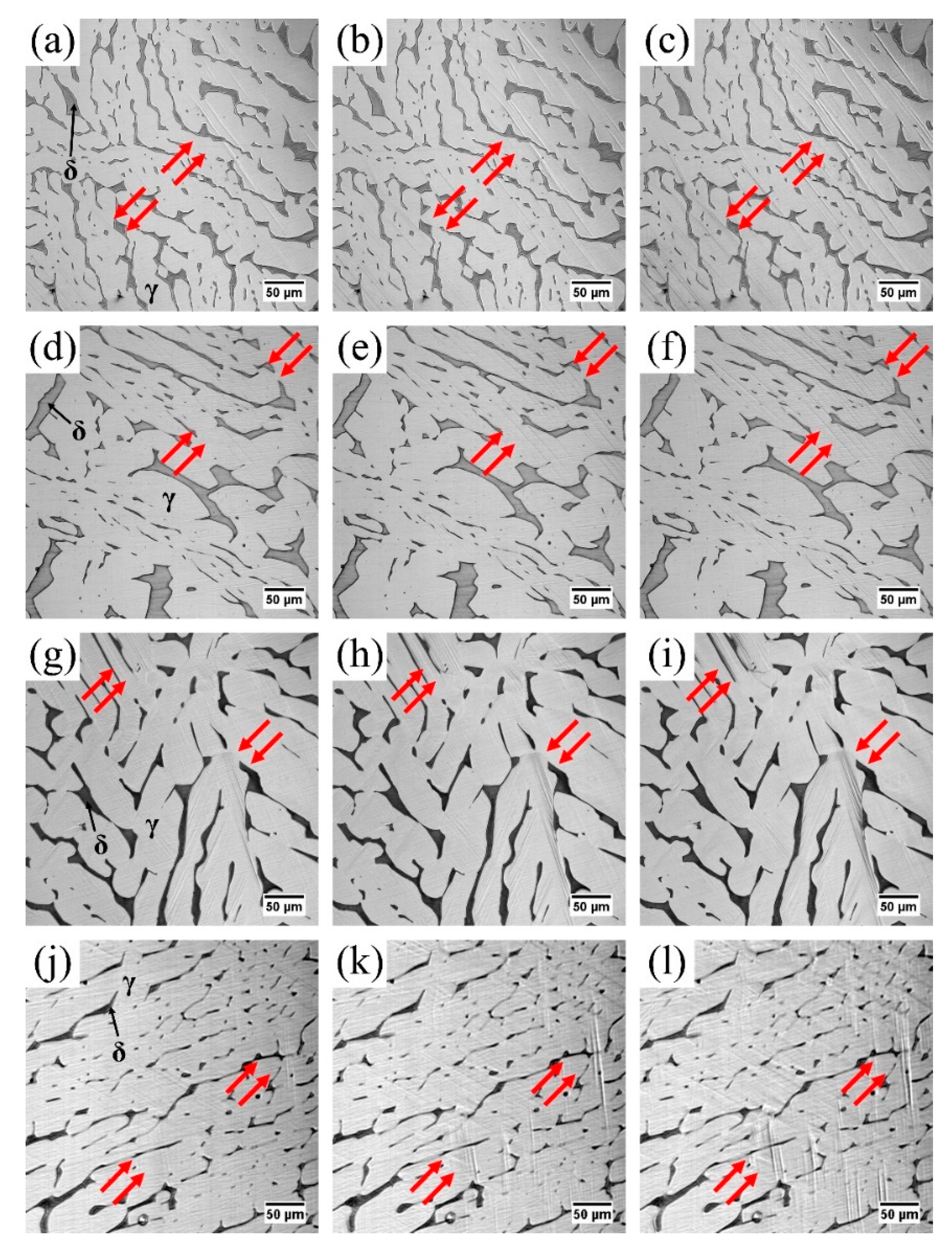
Figure 5 shows the primary stage of the plastic deformation of Z3CN20.09M CDSS under different conditions. The tensile axis is along the horizontal direction in all the figures. In Figure 5, it can be clearly seen that under all the conditions, the straight slip lines are parallel with each other (pointed by the red arrows in Figure 5) which initiate in the austenite phase with most of the lines being terminated at the austenite/ferrite interface boundaries. In addition, with time increasing these slip lines multiply and coarsen to form several slip bands. Such a phenomenon was also observed by Guo [4] and other researchers [27]. In Figure 5, the slip lines in two adjacent austenite phases tend to form along similar directions, which is almost perpendicular to the loading direction. Rajasekhar [35] investigated different modes of solidification process and the steel in our present study can attribute to the “F mode” solidification process that the ferrite phase forms from the liquid metal first, then a certain amount of ferrite transforms to austenite phase. Thus, the misorientation among adjacent austenite phase is small [34]. This causes similar directions of slip lines between the adjacent austenite phases.
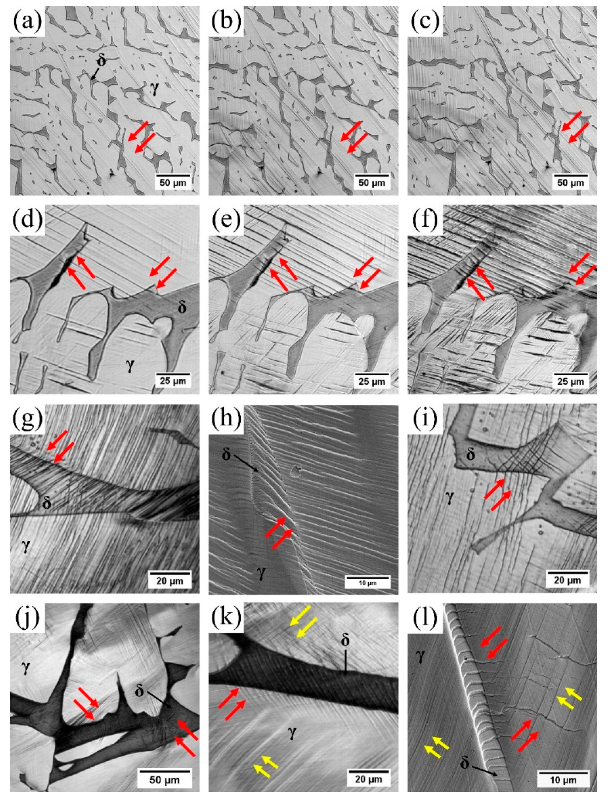
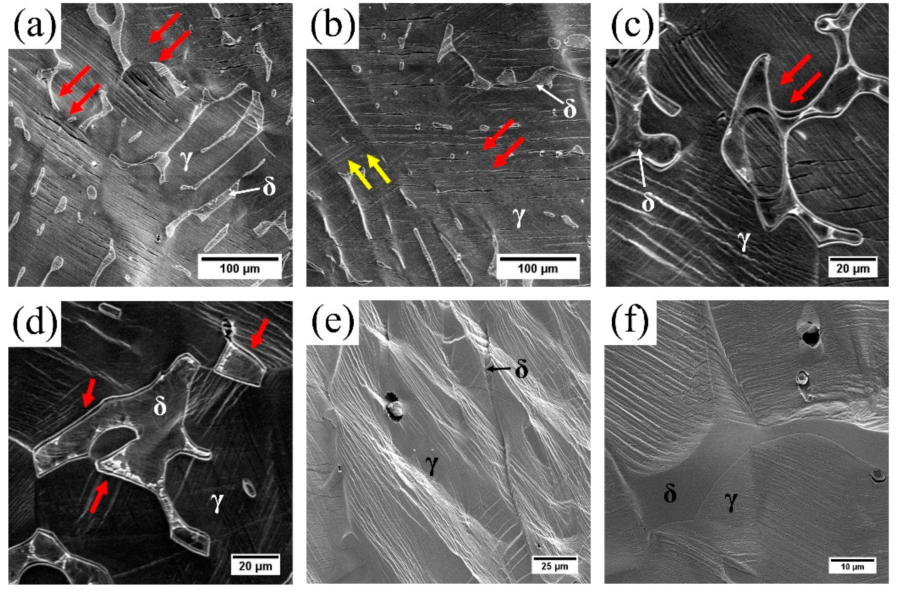
The slip bands between the austenite and ferrite phases can be categorized into several types. Figure 6 shows different types of slip bands between ferrite and austenite phases. In Figure 6a–c, some of the slip lines go across the narrow ferrite grains directly; the same phenomenon can also be found in Figure 5c,l. This indicates that the deformation of such narrow ferrite grains are controlled by the surrounded austenite grains. For some thick ferrite grains, the slip bands in austenite phase tend to bypass the ferrite grains first (shown in Figure 6d), which can be explained by the fact that even though in two-dimensional (2D) view the austenite grains seem to be divided by the ferrite grains, they may actually connect in the 3D view. So in 2D view the slip lines in austenite phases seem to bypass the ferrite grains while they were connected in 3D. Then the slip lines from the austenite grains start to pass through the ferrite grain boundaries (shown in Figure 6e,f). During this process, some slip lines from the austenite phase may not change the stretching directions (Figure 6e,f), some may change the directions with straight lines (Figure 6g), some show curved slip lines in the ferrite grains (Figure 6h) and some may form multiple slip lines in the ferrite phases (Figure 6i). The slip bands form in the austenite phase first, and with the increasing deformation in the phase they start to initiate in the ferrite phase from the interface boundaries where stress concentration easily develops. Since the ferrite phase (bcc) and the austenite phase (fcc) have their own slip systems, the stretching directions of the slip lines in ferrite grains can be different from the adjacent austenite grain. Some slip bands in the ferrite phase may also form in the bulk of the ferrite phase instead of from the austenite/ferrite, as shown in Figure 6j. The situations shown in Figure 6a–j can be found under all the testing conditions, while a certain kind of slip deformation can only be observed in some narrow ferrite grains from the “aged 2000 h, 320 °C” condition. In Figure 6k,l, the slip bands in the ferrite grains pass through the interface boundary and affect the austenite phase, showing a different slip direction (red arrows) from the slip lines in austenite (yellow arrows). This can be attributed to the fact that the hardness of the aged ferrite is much higher than the austenite [11].
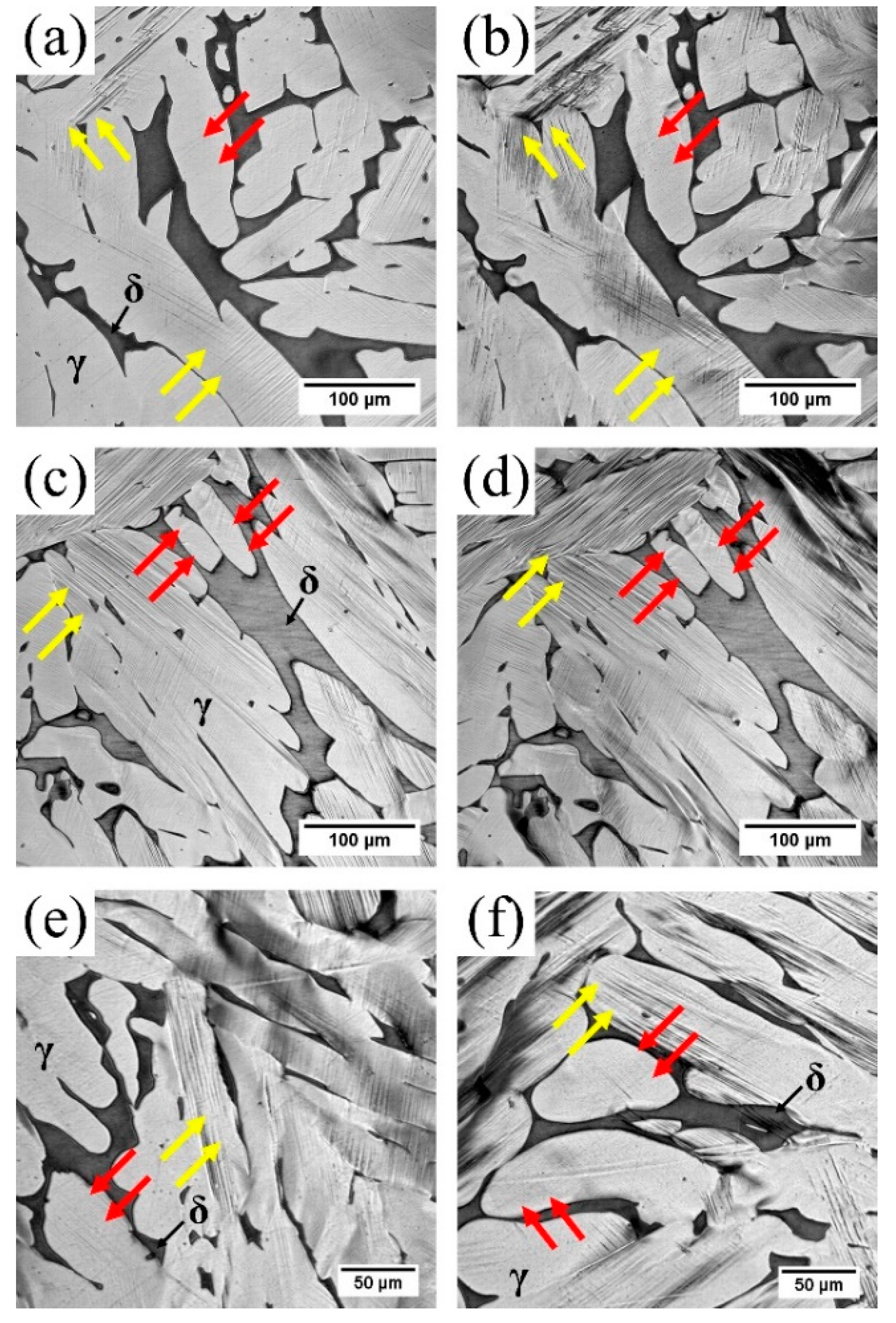
Figure 7 shows the effects of ferrite microstructure on blocking the slip bands. During tensile tests, the local slip lines are dependent on the ferrite distribution. In Figure 7a,c, the initial slip lines occur in the austenite matrix (yellow arrows) while the region that is surrounded by the ferrite grains has no obvious slip lines (red arrows). In Figure 7b,d, with the increasing deformation, the slip lines in austenite matrix are getting coarse while these regions surrounded by ferrite grains are still “flat”, which means only minor deformation occurred. A similar phenomenon is also observed in Figure 7e,f. It can be concluded that the ferrite phase plays a vital role on the deformation in Z3CN20.09M CDSS. Based on our previous study [34], ferrite shows a complex dendritic morphology in 3D view, which can obstruct the plastic deformation in the austenite phase.
3.4. Schematic Diagram of Slip Deformation Mechanisms
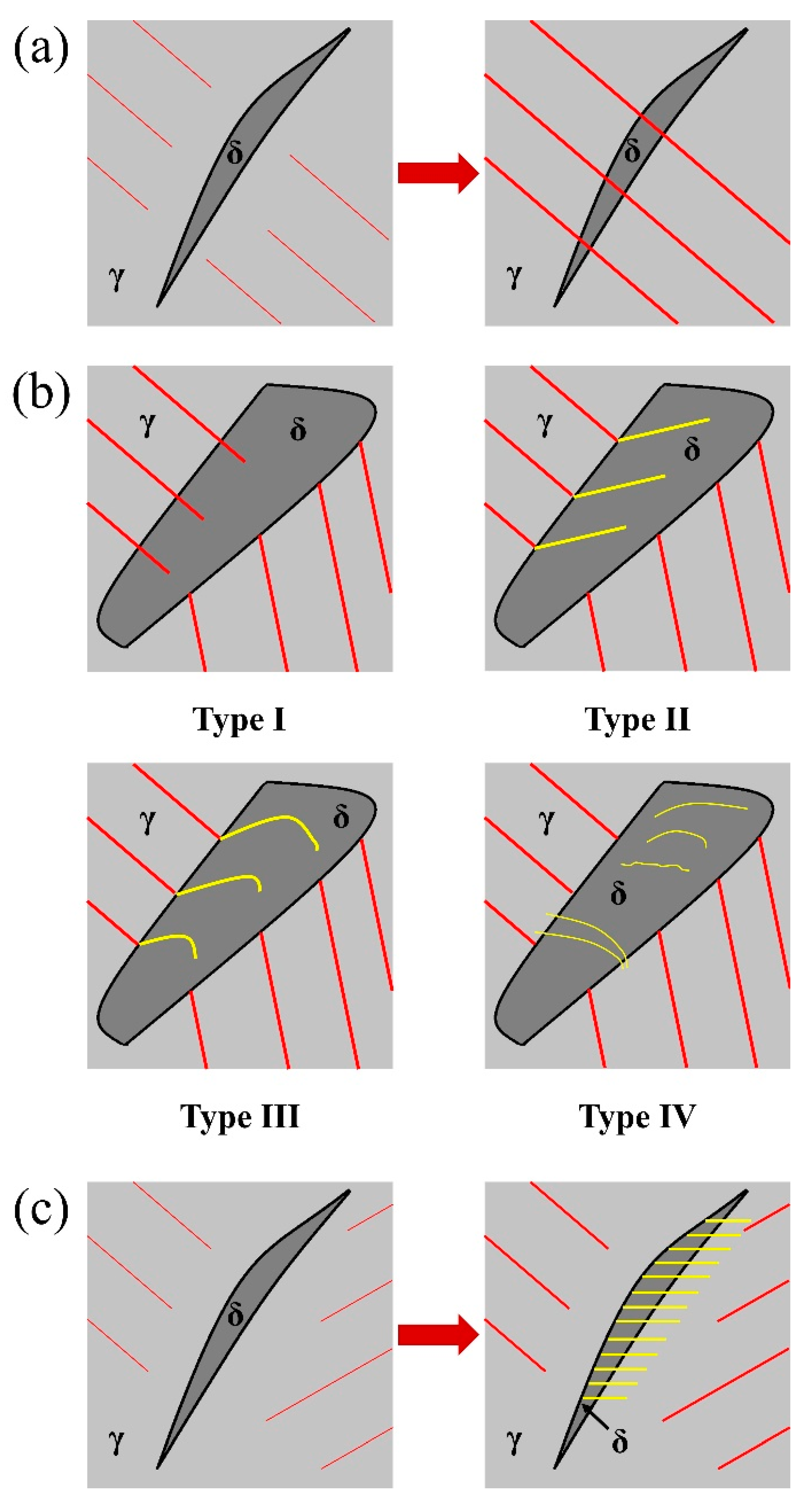
The deformation mechanisms of the Z3CN20.09M can be summarized in Figure 8. The slip lines initiate in the soft austenite matrix, then these slip lines multiply and coarsen to form the slip bands and finally reach the austenite/ferrite interface. Figure 8a is the situation with the narrow ferrite grains, the slip lines go through the ferrite phase directly without changing the direction, and this situation represents Figure 6a–c. For some thick ferrite grains, the slip lines still initiate in the soft austenite matrix and the directions are different on different sides of the ferrite grain. When such slip lines reached the austenite/ferrite interface, four different types of slip deformation could occur, as shown in Figure 8b. In Type I, these slip lines go through the ferrite grain without changing the direction, which represents Figure 6d–f. In Type II, straight slip bands form in the ferrite phase with a new direction, which represents Figure 6g. Type III is similar to condition 2 while the new slip lines are not straight lines, which represents Figure 6h. In Type IV, some slip bands form inside ferrite grain without any connection with the interface boundary, which represents Figure 6j. Most of the slip deformation in this steel can be explained by one or several situations mentioned in Figure 8a,b, e.g. the slip deformation shown in Figure 6i can be explained by the mixture of Type II and Type III. In Figure 8c, a certain kind of slip deformation which was only observed in narrow ferrite grains from the aged steel tested at 320 °C should be noted: the slip bands in ferrite grains pass through the interface boundary and affect the austenite phase, which represents Figure 6k,l.
These different kinds of slip deformation mechanisms can be explained by the crystallographic relation between austenite and ferrite phases. For the face-centered cubic (fcc) austenite there are 12 slip systems ({1 1 1} <1 1 0>) and for the body-centered cubic (bcc) ferrite there are 48 slip systems ({1 1 0} <1 1 1>, {1 1 2} <1 1 1> and {1 2 3} <1 1 1>). To let the slip bands pass through the austenite/ferrite interface boundary, the Kurdjumov–Sachs (KS) crystallographic relation must be satisfied: {1 1 1}γ//{1 1 0}δ and <1 1 0>γ//<1 1 1>δ [36]. When a ferrite grain is plastically compatible with the adjacent austenite grain (the Euler angles achieved by EBSD between these two systems is less than 10 °), the slip bands formed in the austenite phase can pass the austenite/ferrite interface boundary. If the shear of ferrite grain is promoted, the slip bands can pass across the ferrite grain. If not promoted, the slip lines will stop in the ferrite grain [26]. If the ferrite grain is not plastically compatible with the neighboring austenite grain (the angle between these two systems is big), the ferrite grain will show self-plastic activity during tensile process, which represents Figure 6j and Type IV in Figure 8b. Figure 8c also can be explained by the self-plastic activity of ferrite as the hardness of the aged ferrite is much higher than the austenite, the slip bands caused by the self-plastic activity of ferrite affect the adjacent austenite grain.
3.5. Fracture Analysis
With the increasing load, crack sites were found during in situ tensile tests. Figure 9 shows three cases of crack sites in the Z3CN20.09M CDSS. For all the images in Figure 9, the tensile axis moves along the vertical direction. Figure 9a,b show that small cracks initiated in the austenite phase (red arrows), which is also the initiation place of the slip lines. In Figure 9a the cracks were in the same direction with the slip bands (red arrows) and in Figure 9b, the cracks were nearly perpendicular to the loading direction (red arrows) instead of the slip direction (yellow arrows). Such differences can be explained by the different morphologies of the ferrite phase. In Figure 9a, these regions where cracks formed were surrounded by the ferrite phase, which can obstruct the plastic deformation of austenite, so the cracks were caused by the slip bands. In Figure 9b, for the austenite matrix itself, the cracks tend to form along the perpendicular direction of loading axis (red arrows) instead of the slip direction (yellow arrows). This is because the austenite matrix is softer than the ferrite phase and the austenite phase tends to have large grains instead of the complex dendritic ferrite phase. Consequently, the cracks formed in the vertical plane of the loading direction, which has the largest tear strength component force. In Figure 9c,d, the interface boundaries of austenite/ferrite phase was separated. As the phase separation were observed in both the unaged and aged materials, such a phenomenon may not be caused by the spinodal decomposition and G-phase precipitation. Cingara [25] and Guo [4] also found phase separation in duplex phase steel during tensile tests and they explained such a phenomenon as being caused by the decohesion at the interface. Thus, the phase separation shown in Figure 9c,d can be explained by decohesion of the ferrite phase. In Figure 9e,f, the cracks were formed adjacent to the impurities, which are MnS, FeO or a complex combination of a sulfur compound and oxide [4].
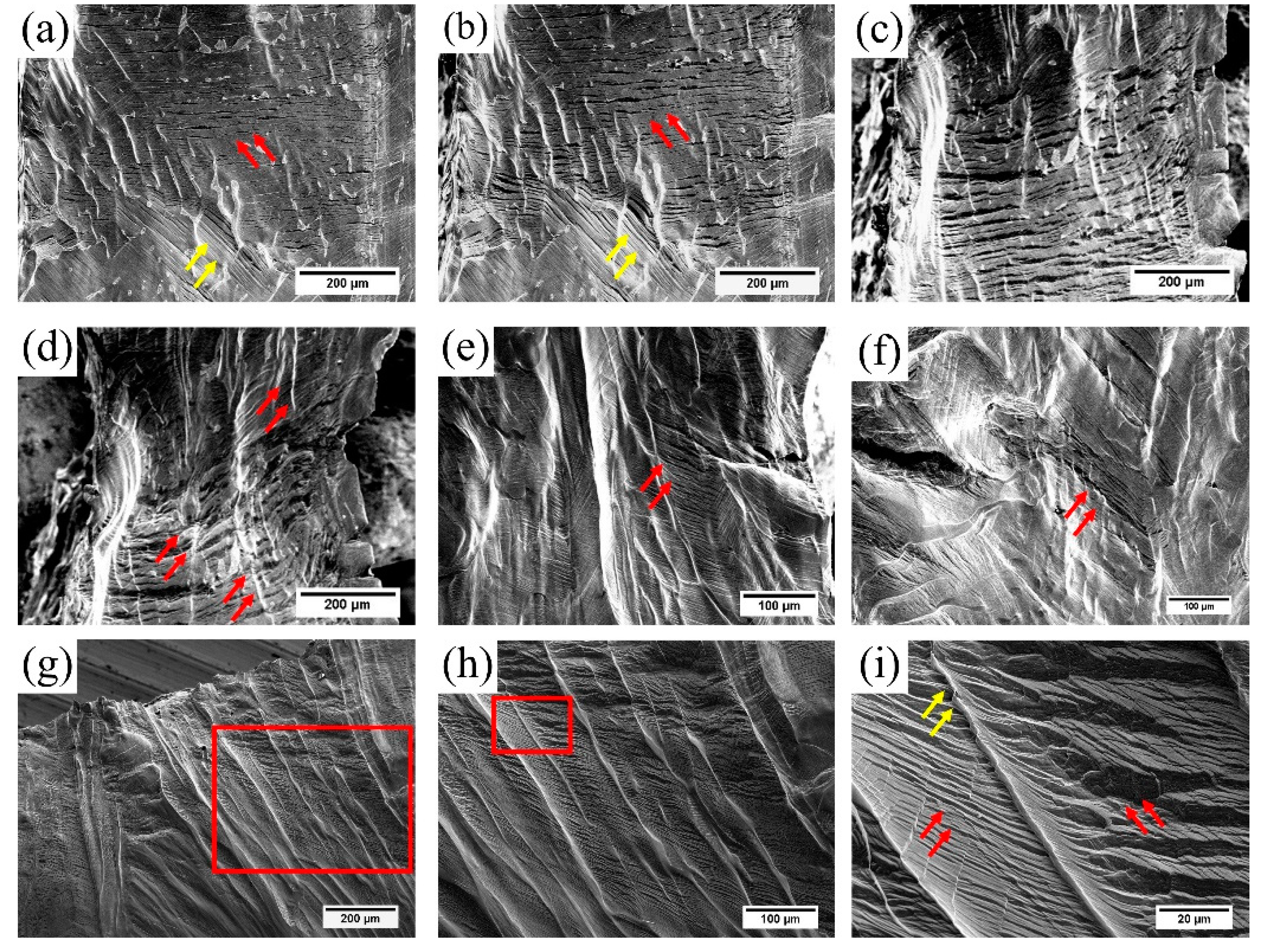
Figure 10 shows the fracture process of the steel. From Figure 10a we can see that there are two kinds of cracks in the specimen: (1) the cracks formed from the slip bands (yellow arrows) and (2) the cracks formed by the tear force (red arrows). With the increasing tensile load, the small cracks propagate and separate the austenite phases (Figure 10b,c). Figure 10d shows the necking deformation, and it is observed that the austenite phase is torn apart and the ferrite phase shows a significant elongation (red arrows). Figure 10g–i show that the ferrite near the fractured region is elongated and rotated (yellow arrows in Figure 10i) with the adjacent austenite phase torn apart (red arrows in Figure 10i). Such phenomena are observed in the samples under all the conditions, as shown in Figure 10e,f. Thus, it can be concluded that the fracture is primarily caused by the failure of the austenite phase and the role of the ferrite phase is to hold the austenite matrix and increase the tensile strength of this steel. This conclusion can also explain the increase on tensile stress in Figure 4 after aging as the hardness of ferrite increases after long-term thermal aging [11,14], thus increasing the tensile strength of the steel.
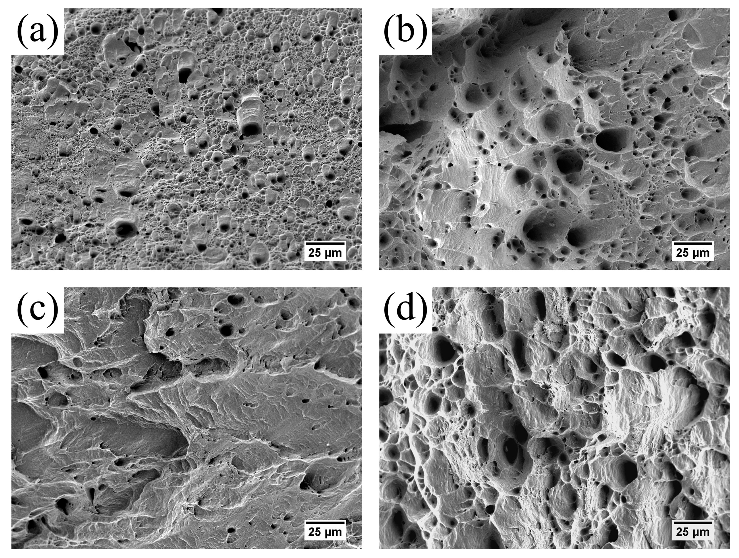
Figure 11 shows the fractographic images of sample under different conditions. Figure 11a shows an obviously ductile fracture with many fine dimples which indicates the as received specimen testing at room temperature has good plasticity. Compared with Figure 11a, Figure 11b also has a ductile fracture with some large dimples, which implies that testing at a high temperature reduces the plasticity of the steel. After being aged for 2000 h, brittle fracture with cleavage faces is observed in Figure 11c. Then after being further annealed at 550 °C for 3 h, the fracture surface in Figure 11d shows the ductile fracture feature to some degree with many some large dimples. Similar results were also found by Guo [4] and Li [15], which can be explained by the reduction in mechanical properties at higher temperature and the thermal aging embrittlement of the ferrite phase, including the “recovery” via anneal heat-treatment [11,13,14,15].
4. Conclusions
In the present work, the in situ tensile behaviors of a thermally-aged cast duplex stainless steel at service temperature (320 °C) was studied. From this study, the following can be concluded:
Working at service temperature will cause degradation in the mechanical properties of CDSS, and the specimens tested at room temperature have the best ductility and the highest tensile stress compared with other specimens tested at 320 °C. For the high temperature tests, the aged specimens show a prominent increase in tensile stress. Then after annealing at 550 °C for 3 h, the tensile properties recovered to almost the same level as the received condition, which is due to the recovery of the thermal aging embrittlement during annealing.
For the slip mechanism, at the primary stage, straight slip lines form first in the austenite phase. Then these slip lines multiply and get coarsen to form the slip bands which reach and are impeded by the austenite/ferrite interface. For the narrow ferrite grains, two kinds of slip systems occur and one kind can only be observed in the aged specimens. For the thick ferrite grains, four kinds of slip systems are observed and discussed.
For the fracture analysis, the crack sites tend to form in the soft austenite matrix, from the slip bands, along the austenite/ferrite interface boundary or in the proximity of the impurities. During the fracture process, the austenite phase is torn apart and the ferrite phase shows a significant elongation. It can be concluded that the fracture is primarily caused by the austenite phase and the role of the ferrite phase is to hold the austenite matrix and increase the tensile strength of the steel.
Author Contributions
Conceptualization, Q.Z. and T.J.; Methodology, Q.Z.; Software, Q.Z.; Validation, Q.Z.; S.M., T.J.; Formal Analysis, Q.Z.; Investigation, Q.Z. and S.M.; Resources, Q.Z. and T.J.; Data Curation, Q.Z. and S.M.; Writing—Original Draft Preparation, Q.Z.; Writing—Review & Editing, S.M., and T.J.; Visualization, Q.Z.; Supervision, T.J.; Project Administration, T.J.; Funding Acquisition, T.J.
Funding
This research received no external funding.
Conflicts of Interest
The authors declare no conflict of interest.
References
- Park, Y.; Lee, Z. The effect of nitrogen and heat treatment on the microstructure and tensile properties of 25Cr–7Ni–1.5Mo–3W–xN duplex stainless steel castings. Mater. Sci. Eng. A 2001, 297, 78–84. [Google Scholar] [CrossRef]
- Pohl, M.; Storz, O.; Glogowski, T. Effect of intermetallic precipitations on the properties of duplex stainless steel. Mater. Charact. 2007, 58, 65–71. [Google Scholar] [CrossRef]
- Li, S.L.; Wang, Y.L.; Wang, X.T. Effects of long term thermal aging on high temperature tensile deformation behaviours of duplex stainless steels. Mater. High Temp. 2015, 32, 524–529. [Google Scholar] [CrossRef]
- Guo, E.; Wang, M.; Jing, T.; Chawla, N. Temperature-dependent mechanical properties of an austenitic–ferritic stainless steel studied by in situ tensile loading in a scanning electron microscope (SEM). Mater. Sci. Eng. A 2013, 580, 159–168. [Google Scholar] [CrossRef]
- Kwon, J.; Woo, S.; Lee, Y.; Park, J.; Park, Y. Effects of thermal aging on the low cycle fatigue behavior of austenitic–ferritic duplex cast stainless steel. Nucl. Eng. Des. 2001, 206, 35–44. [Google Scholar] [CrossRef]
- Weng, K.L.; Chen, H.R.; Yang, J.R. The low-temperature aging embrittlement in a 2205 duplex stainless steel. Mater. Sci. Eng. A 2004, 379, 119–132. [Google Scholar] [CrossRef]
- Iacoviello, F.; Casari, F.; Gialanella, S. Effect of “475 °C embrittlement” on duplex stainless steels localized corrosion resistance. Corros. Sci. 2005, 47, 909–922. [Google Scholar] [CrossRef]
- Xue, F.; Wang, Z.; Shu, G.; Yu, W.; Shi, H.; Ti, W. Thermal aging effect on Z3CN20.09M Cast Duplex Stainless Steel. Nucl. Eng. Des. 2009, 239, 2217–2223. [Google Scholar] [CrossRef]
- Wang, Z.; Xue, F.; Guo, W.; Shi, H.; Zhang, G.; Shu, G. Investigation of thermal aging damage mechanism of the Cast Duplex Stainless Steel. Nucl. Eng. Des. 2010, 240, 2538–2543. [Google Scholar] [CrossRef]
- Li, S.L.; Wang, Y.L.; Zhang, H.L.; Li, S.X.; Zheng, K.; Xue, F.; Wang, X.T. Microstructure evolution and impact fracture behaviors of Z3CN20-09M stainless steels after long-term thermal aging. J. Nucl. Mater. 2013, 433, 41–49. [Google Scholar] [CrossRef]
- Zhang, Q.; Singaravelu, A.S.S.; Zhao, Y.; Jing, T.; Chawla, N. Mechanical properties of a thermally-aged cast duplex stainless steel by nanoindentation and micropillar compression. Mater. Sci. Eng. A 2019, 743, 520–528. [Google Scholar] [CrossRef]
- Li, S.; Wang, Y.; Wang, X.; Xue, F. G-phase precipitation in duplex stainless steels after long-term thermal aging: A high-resolution transmission electron microscopy study. J. Nucl. Mater. 2014, 452, 382–388. [Google Scholar] [CrossRef]
- Yamada, T.; Okano, S.; Kuwano, H. Mechanical property and microstructural change by thermal aging of SCS14A cast duplex stainless steel. J. Nucl. Mater. 2006, 350, 47–55. [Google Scholar] [CrossRef]
- Li, S.L.; Zhang, H.L.; Wang, Y.L.; Li, S.X.; Zheng, K.; Xue, F.; Wang, X.T. Annealing induced recovery of long-term thermal aging embrittlement in a duplex stainless steel. Mater. Sci. Eng. A 2013, 564, 85–91. [Google Scholar] [CrossRef]
- Li, S.; Wang, Y.; Li, S.; Zhang, H.; Xue, F.; Wang, X. Microstructures and mechanical properties of cast austenite stainless steels after long-term thermal aging at low temperature. Mater. Design. 2013, 50, 886–892. [Google Scholar] [CrossRef]
- Stewart, J.L.; Jiang, L.; Williams, J.J.; Chawla, N. Prediction of bulk tensile behavior of dual phase stainless steels using constituent behavior from micropillar compression experiments. Mater. Sci. Eng. A 2012, 534, 220–227. [Google Scholar] [CrossRef]
- Stewart, J.L.; Williams, J.J.; Chawla, N. Influence of Thermal Aging on the Microstructure and Mechanical Behavior of Dual-Phase, Precipitation-Hardened, Powder Metallurgy Stainless Steels. Metall. Mater. Trans. A 2012, 43, 124–135. [Google Scholar] [CrossRef]
- Kamiya, O.; Kumagai, K.; Kikuchi, Y. Effects of delta ferrite morphology on low-temperature fracture toughness of austenitic stainless steel weld metal. Weld. Int. 1992, 6, 606–611. [Google Scholar] [CrossRef]
- Shiao, J.J.; Tsai, C.H.; Kai, J.J.; Huang, J.H. Aging embrittlement and lattice image analysis in a Fe-Cr-Ni duplex stainless steel aged at 400 °C. J. Nucl. Mater. 1994, 217, 269–278. [Google Scholar] [CrossRef]
- Timofeev, B.T.; Nikolaev, Y.K. About the prediction and assessment of thermal embrittlement of Cr–Ni austenitic–ferritic weld metal and castings at the ageing temperatures 260–425°C. Int. J. Pres. Ves. Pip. 1999, 76, 849–856. [Google Scholar] [CrossRef]
- Chen, T.H.; Weng, K.L.; Yang, J.R. The effect of high-temperature exposure on the microstructural stability and toughness property in a 2205 duplex stainless steel. Mater. Sci. Eng. A 2002, 338, 259–270. [Google Scholar] [CrossRef]
- Chéhab, B.; Bréchet, Y.; Véron, M.; Jacques, P.J.; Parry, G.; Mithieux, J.D.; Glez, J.C.; Pardoen, T. Micromechanics of high-temperature damage in dual-phase stainless steel. Acta Mater. 2010, 58, 626–637. [Google Scholar] [CrossRef]
- Li, S.; Wang, Y.; Zhang, H.; Li, S.; Wang, G.; Wang, X. Effects of prior solution treatment on thermal aging behavior of duplex stainless steels. J. Nucl. Mater. 2013, 441, 337–342. [Google Scholar] [CrossRef]
- Tavares, S.S.M.; Feijó, G.F.; Farneze, H.N.; Sandim, M.J.R.; Souza Filho, I.R.D. Influence of Microstructure on the Corrosion Resistance of AISI 317L (UNS S31703). Mater. Res. 2017, 20, 108–114. [Google Scholar] [CrossRef] [Green Version]
- Avramovic-Cingara, G.; Ososkov, Y.; Jain, M.K.; Wilkinson, D.S. Effect of martensite distribution on damage behaviour in DP600 dual phase steels. Mater. Sci. Eng. A 2009, 516, 7–16. [Google Scholar] [CrossRef]
- Serre, I.; Salazar, D.; Vogt, J.B. Atomic force microscopy investigation of surface relief in individual phases of deformed duplex stainless steel. Mater. Sci. Eng. A 2008, 492, 428–433. [Google Scholar] [CrossRef]
- Wang, Y.; Yao, Y.H.; Wang, Z.P.; Jin, Y.H.; Zhang, X.L.; Liu, J.N. Thermal ageing on the deformation and fracture mechanisms of a duplex stainless steel by quasi in-situ tensile test under OM and SEM. Mater. Sci. Eng. A 2016, 666, 184–190. [Google Scholar] [CrossRef]
- Byun, T.S.; Yang, Y.; Overman, N.R.; Busby, J.T. Thermal Aging Phenomena in Cast Duplex Stainless Steels. Jom-Us 2016, 68, 507–516. [Google Scholar] [CrossRef]
- McNaught, A.D.; Wilkinson, A. IUPAC Compendium of Chemical Terminology, 2nd ed.; Blackwell Science Publications: Oxford, UK, 1997; p. 111. [Google Scholar]
- Byun, T.S.; Hashimoto, N.; Farrell, K. Temperature dependence of strain hardening and plastic instability behaviors in austenitic stainless steels. Acta Mater. 2004, 52, 3889–3899. [Google Scholar] [CrossRef]
- Choudhary, B.K.; Samuel, E.I.; Sainath, G.; Christopher, J.; Mathew, M.D. Influence of Temperature and Strain Rate on Tensile Deformation and Fracture Behavior of P92 Ferritic Steel. Metall. Mater. Trans. A 2013, 44, 4979–4992. [Google Scholar] [CrossRef]
- Liu, G.; Wang, Y.; Li, S.; Du, K.; Wang, X. Deformation behavior of thermal aged duplex stainless steels studied by nanoindentation, EBSD and TEM. Mater. High Temp. 2016, 33, 15–23. [Google Scholar] [CrossRef]
- Hollomon, J.H. Tensile deformation. Trans. AIME 1945, 162, 268–290. [Google Scholar]
- Zhang, Q.; Niverty, S.; Singaravelu, A.S.S.; Williams, J.J.; Guo, E.; Jing, T.; Chawla, N. Microstructure and micropore formation in a centrifugally-cast duplex stainless steel via X-ray microtomography. Mater. Charact. 2019, 148, 52–62. [Google Scholar] [CrossRef]
- Rajasekhar, K.; Harendranath, C.S.; Raman, R.; Kulkarni, S.D. Microstructural evolution during solidification of austenitic stainless steel weld metals: A color metallographic and electron microprobe analysis study. Mater. Charact. 1997, 38, 53–65. [Google Scholar] [CrossRef]
- Zieliński, W.; Świątnicki, W.; Barstch, M.; Messerschmidt, U. Non-uniform distribution of plastic strain in duplex steel during TEM in situ deformation. Mater. Chem. Phys. 2003, 81, 476–479. [Google Scholar] [CrossRef] [Green Version]
Figure 1.
Typical microstructure of the Z3CN20.09M cast duplex stainless steel.

Figure 2.
(a) The in situ tensile testing stage of VL2000DX-SVF15FTC high temperature confocal scanning violet laser microscope and (b) the dimensions of the specimen.
Figure 2.
(a) The in situ tensile testing stage of VL2000DX-SVF15FTC high temperature confocal scanning violet laser microscope and (b) the dimensions of the specimen.

Figure 3.
TEM results of Z3CN20.09M. (a) Aged at 475 °C for 2000 h and (c) aged at 475 °C for 2000 h then annealed at 550 °C for 3 h. (b,d) are the corresponding electron diffraction (ED) pattern of (a,c), respectively.
Figure 3.
TEM results of Z3CN20.09M. (a) Aged at 475 °C for 2000 h and (c) aged at 475 °C for 2000 h then annealed at 550 °C for 3 h. (b,d) are the corresponding electron diffraction (ED) pattern of (a,c), respectively.

Figure 4.
Stress-strain curves of Z3CN20-09M stainless steel with different aging conditions: (a) engineering stress–strain curves and (b) the corresponding true stress–strain curves. Here the “as received, 20 °C” represents the as received specimens condition tested at 20 °C; the “as received, 320 °C” represents the as received specimens condition tested at 320 °C; “aged 2000 h, 320 °C” represents the aged at 475 °C for 2000 h condition tested at 320 °C and “annealed 3 h, 320 °C” represents the aged at 475 °C for 2000 h then annealed at 550 °C for 3 h condition tested at 320 °C.

Figure 5.
The primary stage of the plastic deformation of Z3CN20.09M CDSS. Figure (a–c) were the “as received, 20 °C” condition. Figure (d–f) were the “as received, 320 °C” condition. Figure (g–i) were the “aged 2000 h, 320 °C” condition. Figure (j–l) were the “annealed 3 h, 320 °C” condition. The tensile axis is along the horizontal direction in all the figures. denotes austenite phase, and is the ferrite phase.

Figure 6.
Different types of slip bands between ferrite and austenite phases in Z3CN20.09M CDSS. Figure (a–f) were the microstructure snapshots during the in situ tensile test using the sample with the “as received, 20 °C” condition. Figure (g–i) were the results from the samples with the “annealed 3 h, 320 °C” condition. Figure (j–l) were microstructures using the sample under the “aged 2000 h, 320 °C” condition. It should be noted that Figure (h,l) were imaged by SEM after the tensile tests and their tensile axis is the vertical direction. In other images, the tensile axis is along the horizontal direction. denotes austenite phase, and is the ferrite phase.

Figure 7.
Effects of ferrite shapes on blocking the slip bands in Z3CN20.09M CDSS. Figure (a,b,e,f) were the microstructure snapshots during the in situ tensile test using the samples under the “aged 2000 h, 320 °C” condition. Figure (c,d) were the microstructures from the sample with the “annealed 3 h, 320 °C” condition. The tensile axis is along the horizontal direction in all the figures. denotes the austenite phase, and is the ferrite phase.

Figure 8.
The slip deformation mechanisms of the Z3CN20.09M. (a) Narrow ferrite grains; (b) thick ferrite grains and (c) a certain kind of slip deformation that only happened in the thermally aged steel.
Figure 8.
The slip deformation mechanisms of the Z3CN20.09M. (a) Narrow ferrite grains; (b) thick ferrite grains and (c) a certain kind of slip deformation that only happened in the thermally aged steel.

Figure 9.
Crack sites in the Z3CN20.09M CDSS during tensile tests. In Figure (a,b), small cracks initiated in the austenite phase. In Figure (c,d), the interface boundaries of austenite/ferrite phase were separated. In Figure (e,f), the cracks were formed adjacent to the impurities. Figure (a–d) were from the samples under the “as received, 320 °C” condition tested by Shimadzu SS550, Figure (e,f) were from the samples under the “aged 2000 h, 320 °C” condition which were imaged by SEM after tensile tests. The tensile axis moves along the vertical direction in all the figures.

Figure 10.
Fracture process in Z3CN20.09M CDSS during tensile tests. Figure (a–f) were from the samples under the “as received, 320 °C” condition with the same region; Figure (e) was from the sample under the “aged 2000 h, 320 °C” condition; Figure (f) was from the sample under the “annealed 3 h, 320 °C” condition. Figure (a–f) were all tested by Shimadzu SS550. Figure (g,h) were from the samples under the “as received, 320 °C” condition then imaged by SEM after tensile tests. Figure (h) is the magnified image of the rectangular region in Figure (g), and Figure (i) is the magnified image of the rectangular region in Figure (h). The tensile axis moves along the vertical direction in all the figures.

Figure 11.
Fractographic image of Z3CN20.09M CDSS with different tensile conditions. (a) The “as received, 20 °C” condition; (b) the “as received, 320 °C” condition; (c) the “aged 2000 h, 320 °C” condition; (d) the “annealed 3 h, 320 °C” condition. Figures are imaged by SEM after tensile tests.
Figure 11.
Fractographic image of Z3CN20.09M CDSS with different tensile conditions. (a) The “as received, 20 °C” condition; (b) the “as received, 320 °C” condition; (c) the “aged 2000 h, 320 °C” condition; (d) the “annealed 3 h, 320 °C” condition. Figures are imaged by SEM after tensile tests.


Table 1.
Chemical composition of the tested Z3CN20-09M cast duplex stainless steel (wt. %).
| Cr | Ni | Mn | Si | C | P | S | Cu | Mo | Fe |
|---|---|---|---|---|---|---|---|---|---|
| 20.895 | 8.755 | 0.84 | 1.04 | 0.03 | 0.02 | 0.004 | 0.015 | 0.349 | Bal |
Table 2.
Mechanical properties of the tested Z3CN20-09M CDSS with different heat-treatment conditions.
Table 2.
Mechanical properties of the tested Z3CN20-09M CDSS with different heat-treatment conditions.
| Conditions | Yield Stress (MPa) | UTS (MPa) | Uniform Elongation (%) | Total Elongation (%) | Strength Coefficient (MPa) | Strain Hardening Exponent |
|---|---|---|---|---|---|---|
| As received–20 °C | 249 ± 9 | 548 ± 2 | 31.3 ± 3.1 | 32.9 ± 3.1 | 1290 ± 25 | 0.512 ± 0.030 |
| As received–320 °C | 147 ± 4 | 378 ± 11 | 18.1 ± 1.3 | 19.7 ± 1.5 | 1057 ± 18 | 0.477 ± 0.014 |
| Aged for 2000 h–320 °C | 165 ± 1 | 427 ± 16 | 17.2 ± 0.7 | 18.1 ± 0.9 | 1154 ± 31 | 0.448 ± 0.009 |
| Aged 2000 h annealed 3 h–320 °C | 141 ± 5 | 369 ± 20 | 16.2 ± 1.7 | 17.6 ± 2.8 | 1077 ± 44 | 0.477 ± 0.007 |
© 2019 by the authors. Licensee MDPI, Basel, Switzerland. This article is an open access article distributed under the terms and conditions of the Creative Commons Attribution (CC BY) license (http://creativecommons.org/licenses/by/4.0/).
Share and Cite
MDPI and ACS Style
Zhang, Q.; Ma, S.; Jing, T. Mechanical Properties of a Thermally-aged Cast Duplex Stainless Steel by in Situ Tensile Test at the Service Temperature. Metals 2019, 9, 317. https://doi.org/10.3390/met9030317
AMA Style
Zhang Q, Ma S, Jing T. Mechanical Properties of a Thermally-aged Cast Duplex Stainless Steel by in Situ Tensile Test at the Service Temperature. Metals. 2019; 9(3):317. https://doi.org/10.3390/met9030317
Chicago/Turabian StyleZhang, Qingdong, Sida Ma, and Tao Jing. 2019. "Mechanical Properties of a Thermally-aged Cast Duplex Stainless Steel by in Situ Tensile Test at the Service Temperature" Metals 9, no. 3: 317. https://doi.org/10.3390/met9030317
Note that from the first issue of 2016, this journal uses article numbers instead of page numbers. See further details here.