Coarse Grained Heat-Affected Zone Microstructure and Brittleness of Ti-Nb-B Microalloyed High Toughness and Wear Resistant Steel

1
The State Key Laboratory of Refractories and Metallurgy, Hubei Province Key Laboratory of Systems Science on Metallurgical Processing, International Research Institute for Steel Technology, Wuhan University of Science and Technology, Wuhan 430081, China
2
Wuhan Branch of Baosteel Central Research Institute (R & D Center of Wuhan Iron & Steel Co., Ltd.), Wuhan 430080, China
*
Authors to whom correspondence should be addressed.
Metals 2019, 9(3), 289; https://doi.org/10.3390/met9030289
Submission received: 11 February 2019
/
Revised: 18 February 2019
/
Accepted: 22 February 2019
/
Published: 4 March 2019
Abstract
:The effects of B, Ti-Nb, and Ti-Nb-B microalloying on the microstructure and properties of the coarse grain heat affected zone (CGHAZ) of C-Mn-Si-Mo wear-resistant steel have been investigated by means of thermal simulation, mechanical property test, microstructure analysis, and theoretical formula calculation. The B, Ti-Nb, and Ti-Nb-B microalloyed C-Mn-Si-Mo wear-resistant steels prepared by a controlled rolling + direct quenching + low temperature (CR + DQ + T) process have martensite/bainite (M/B) dual-phase microstructure and fully-refined effective grain size, which make the base metal to have high hardness and impact toughness. At the heat input of 20 kJ/cm, the impact toughness of CGHAZ of three kinds of microalloyed wear-resistant steels decreased in varying degrees. The main reasons for brittleness were coarse grain embrittlement and microstructural embrittlement. Ti-Nb-B microalloying can effectively prevent grain growth in CGHAZ while avoiding the formation of pearlite, small lump ferrite, and large grain carbides at the grain boundaries, thereby reducing the embrittlement of coarse grain and microstructure.
1. Introduction
The rapid development of industry requires long-lasting performance of wear-resistant steel. It is common to increase the carbon content and multi-alloying to increase the hardness but this results in poor solderability of the material [1]. During the welding process, different regions of the base metal are subjected to different welding thermal cycles, resulting in uneven microstructure and mechanical properties of the weld heat affected zone (HAZ). Dudziński et al. [2] reported that when the temperature peak is too high and the cooling rate is slow, the coarse-grained heat-affected zone (CGHAZ) stays in the high-temperature zone for a long time, which makes the austenite grain coarser. After the phase transformation is completed, the grain in the region become coarser and the local embrittlement is severe, which results in the poor welding performance of high hardness and wear resistant steel. It is generally believed that the embrittlement of the weld heat affected zone is related to the chemical composition, microstructure, and the welding process of the parent metal, and there are complex links among various factors, so this problem has been highly concerning.
At present, the research on CGHAZ of wear-resistant steel is mainly focused on welding heat input, only a few studies have focused on the influence of the composition and microstructure of the base metal. In this paper, controlled rolling (CR) + direct quenching (DQ) + low temperature tempering (T) processes have been used to obtain high hardness and high toughness wear-resistant steels with different compositions of microalloying. The effect of microalloying composition on the brittleness of CGHAZ is studied under the condition of a large welding heat input.
2. Experimental Materials and Methods
Considering the influence of chemical composition on the structure transformation, solid solution strengthening, fine grain strengthening, precipitation strengthening, and other factors, the carbon equivalent should be controlled within the weldable range [3]. By taking C-Mn-Si-Mo as the base chemical composition and adding appropriate amounts of B, Ti-Nb, or Ti-Nb-B, the chemical composition of three microalloyed wear-resistant steels was derived (Table 1).
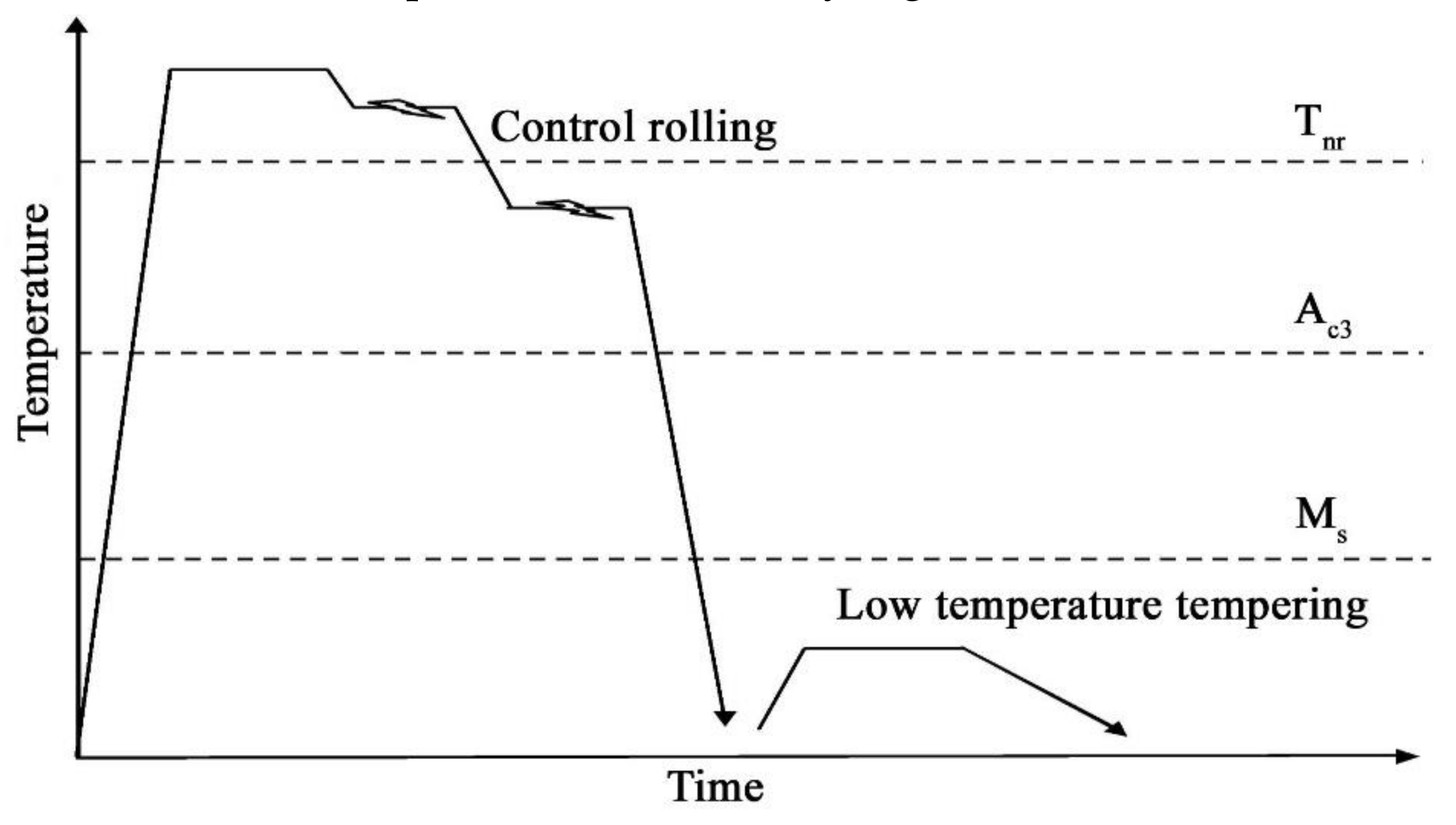
The samples were smelted by a vacuum induction furnace, casted into a 50-kg steel ingot, and then billeted into a hot rolled billet (170 mm × 170 mm × 220 mm). After the billet was heated to 1250 °C for 3 h and heat treated by CR + DQ + T process, it was finally processed into a steel plate with a thickness of 12 mm. The CR + DQ + T process are shown by Figure 1.
Each test steel was processed into five 90 mm (in the rolling direction) × 11 mm × 11 mm specimens. Table 2 has shown the process of welding thermal simulation, where Cooling time (t8/5) is the cooling time from 800 to 500 °C, which will finally decide the phase transition products in HAZ [1]. The single pass welding thermal cycle of the test steel was carried out on a Gleeble–3800 (Dynamic Systems Inc., Tarrytown, NY, US) thermal simulator to simulate CGHAZ, to determine the mechanical properties, and to observe microstructure.
The hardness was measured by using a BRIN200D-TL semi-automatic Brinell hardness tester (Foundrax, Somerset, UK). The impact energy sample had the dimensions of 10 mm × 10 mm × 55 mm and the measurements were taken on a ZBC 2452–3 (MTS, Eden Prairie, MN, US) pendulum impact tester. The metallographic samples were etched with 4% nitric acid and the microstructure was observed under a LEI2CAQ5501IW (Leica, Buffalo Grove, IL, US) optical microscope. After grinding and polishing, the austenite grain boundary was corroded by saturated picric acid and detergent, and the grain size grade was evaluated by truncation method according to GB/T 6394–2002. The specimens for transmission electron microscopy (TEM) were prepared by carbon membrane extraction replica method and observed under JEM–2100F (JEOL, Tokyo, Japan). The specimen was produced as following process, a thin carbon layer (250 nm) was deposited on the polished sample surface by using a vacuum evaporator, then scratched and divided into several 2 mm squares, finally fished out on Cu-grids and then washed in ethanol. The size of the particles was counted by the truncation method and the precipitated phase was analyzed by INCA energy spectrometer (Oxford, UK). The TEM film samples were prepared and the microstructure of the samples was observed and analyzed in a JEM–2100F.
3. Results
3.1. Properties and Microstructure of the Base Metal
The mechanical properties of the three kinds of base metal are shown in Table 3. The hardness of sample #1 reaches the requirement of 450 grade wear-resistant steel; while samples #2 and #3 meet the requirements of the 500-grade wear-resistant steel. All three samples have high impact toughness.
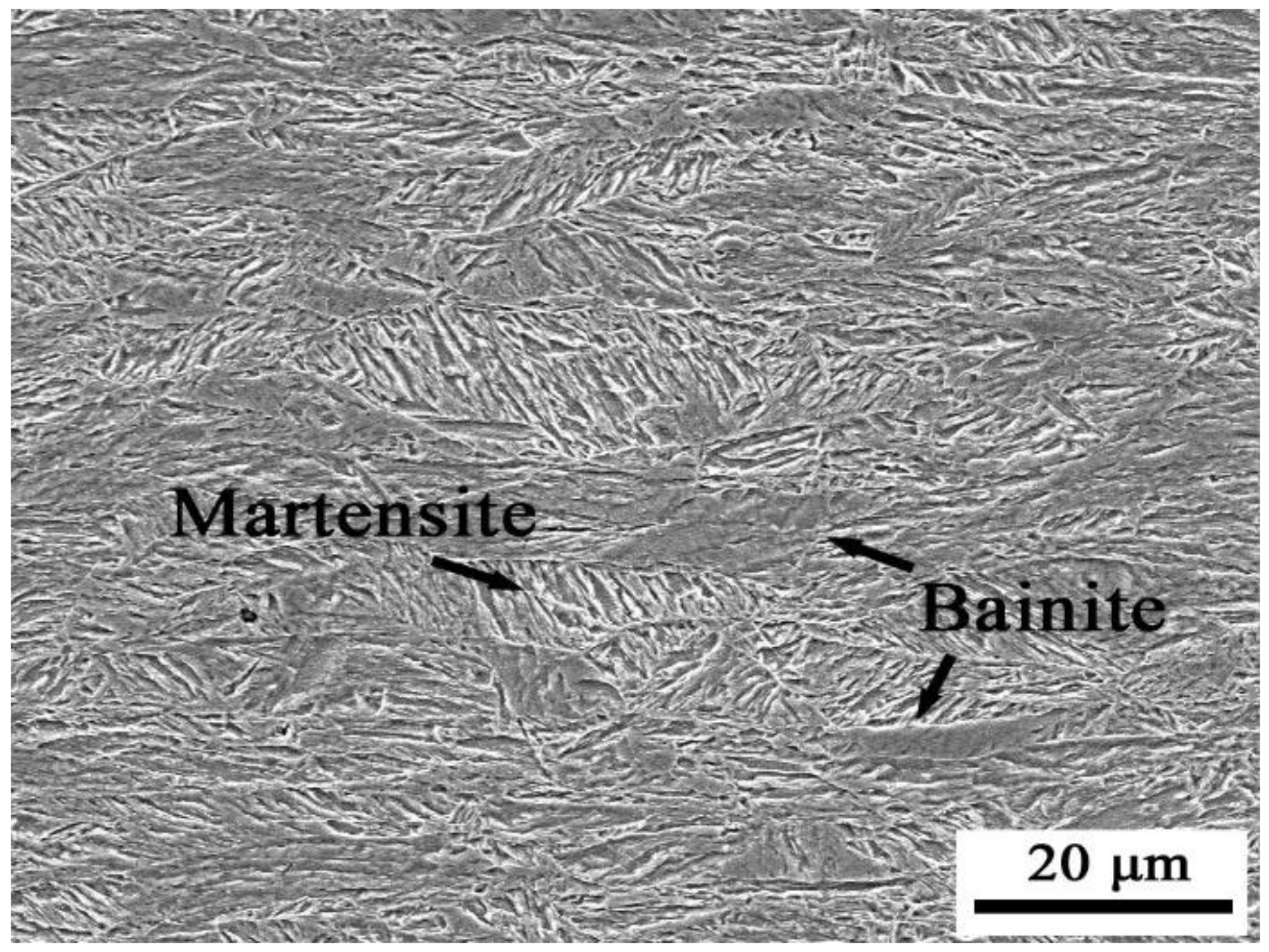
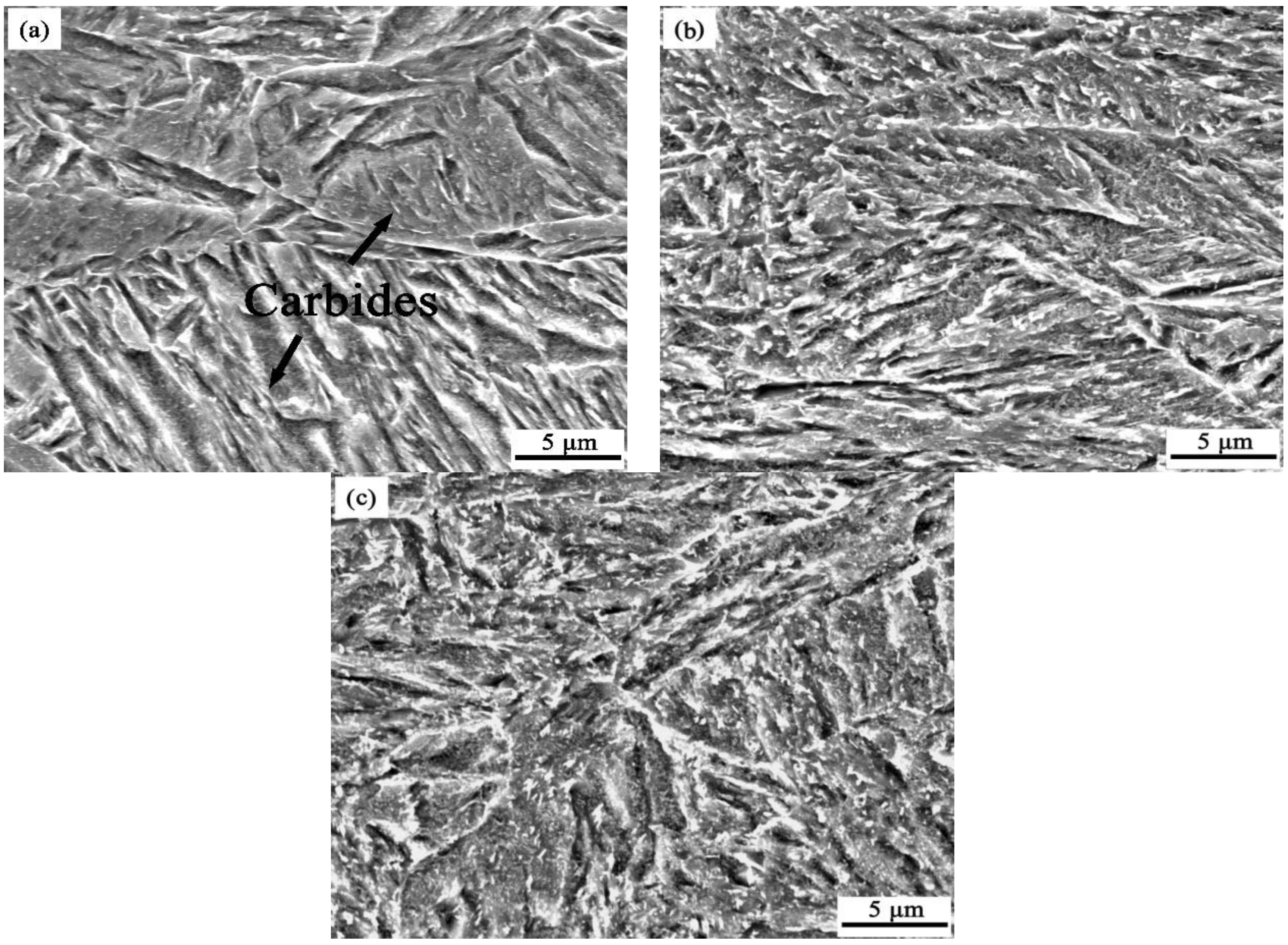
During the CR process, austenite grains are fully broken and refined during repeated recrystallization by rolling at a high reduction rate in the recrystallization zone. However, in the austenite non-recrystallization zone, a large number of dislocations are generated as austenite grains are distorted by rolling at a high reduction rate and low temperature. Lattice distortion and dislocation can reduce the activation energy for stress induced phase transition nucleation but can increase the nucleation site. Austenite grains are divided into small areas by bainite lath that is transformed initially during the DQ process, and then to a martensite phase transition in the small areas. The martensite lath grows in many directions and some amount of that penetrates the austenite. The martensite blocks are quite narrow and intersect each other. Microstructures are fully refined during the CR and DQ processes, as shown in Figure 2. After direct quenching, during the low temperature tempering, carbides precipitate out of the matrix, while the morphology of microstructure does not change evidently and the grain boundary remains clear. As shown in Figure 3, the SEM microstructures of the three samples are uniform and fine, all are tempered martensite with a small amount of bainite. Through the CR + DQ + T process, the effective grain size [4] can be refined to make the base material have high hardness and good impact toughness [5], which could be explored in further studies about the brittleness of wear-resistant steel welded CGHAZ. Under the conditions of high reduction rate, high cooling rate, and low tempering temperature, it can be seen that Ti, Nb, and B have little effect on the microstructure and mechanical properties of the base metal.
3.2. Properties and Microstructure of Coarse Grain Heat Affected Zone
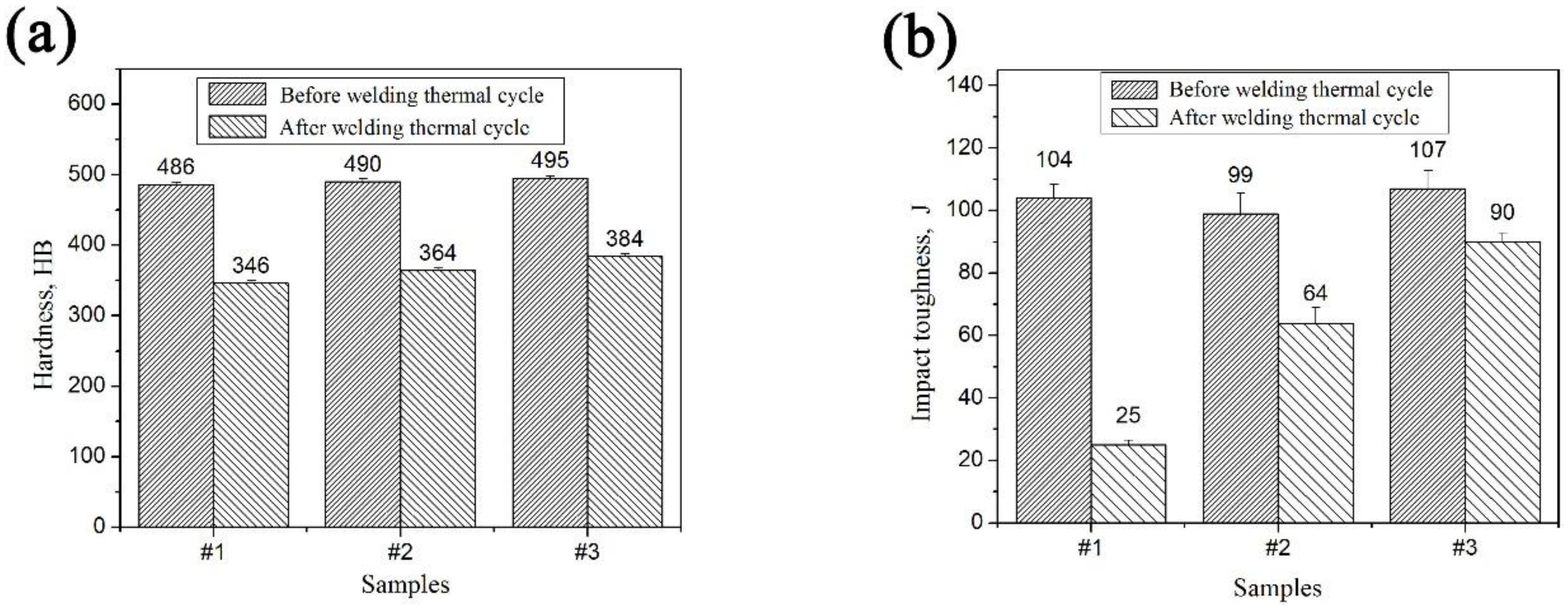
The hardness and impact toughness of the CGHAZ obtained from the three samples after single pass welding thermal cycling process are shown in Table 4. Compared with the base metal, the hardness of CGHAZ of samples #1, #2 and #3 was decreased by 28.8%, 25.8%, and 22.4%, respectively, while the toughness of the same samples was decreased by 75.9%, 35.4%, and 15.1%, respectively. The CGHAZ of the three samples showed different degrees of embrittlement, among which sample #1 was the most serious embrittlement phenomenon, and sample #3 showed good anti-brittleness.
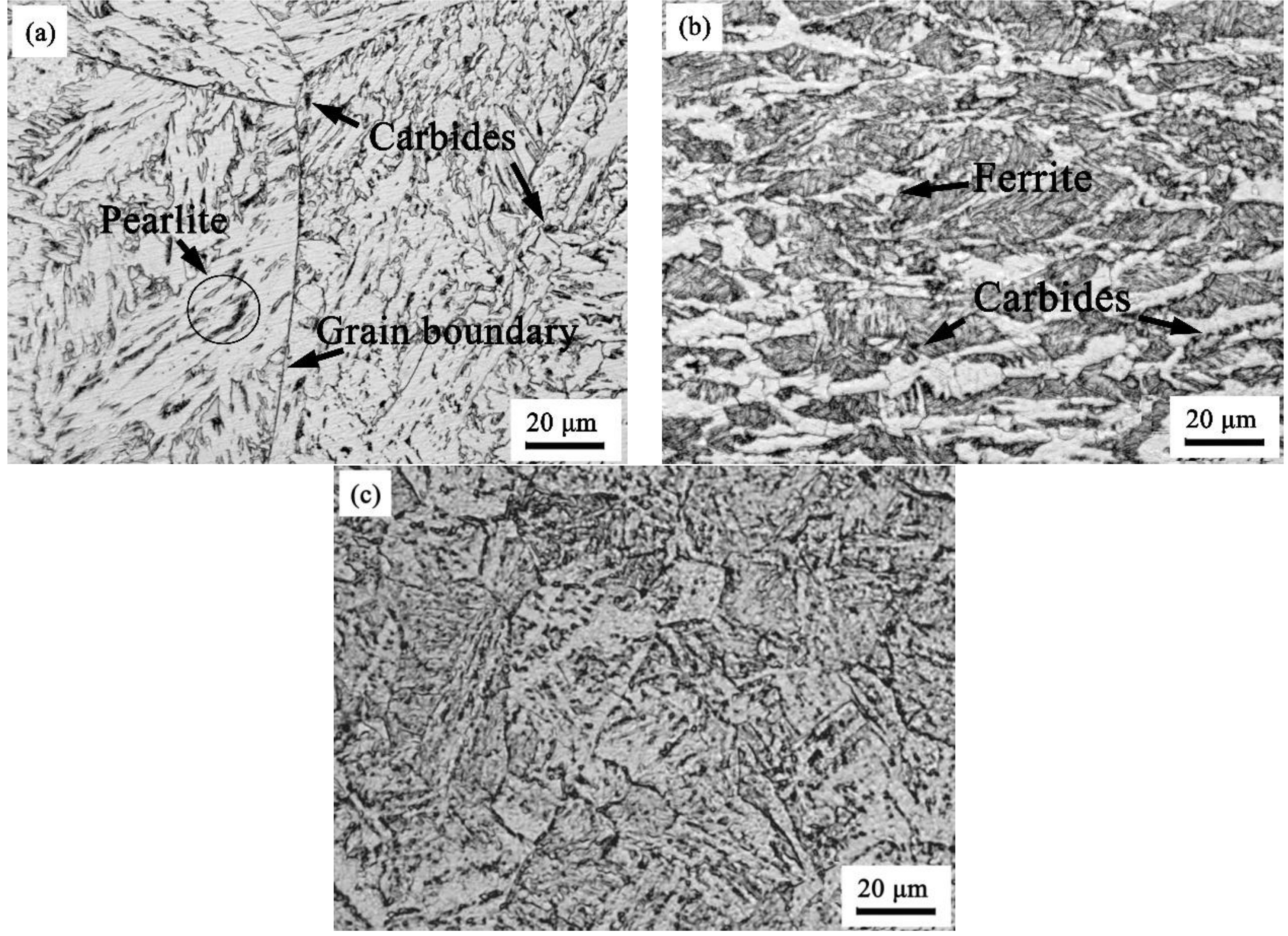
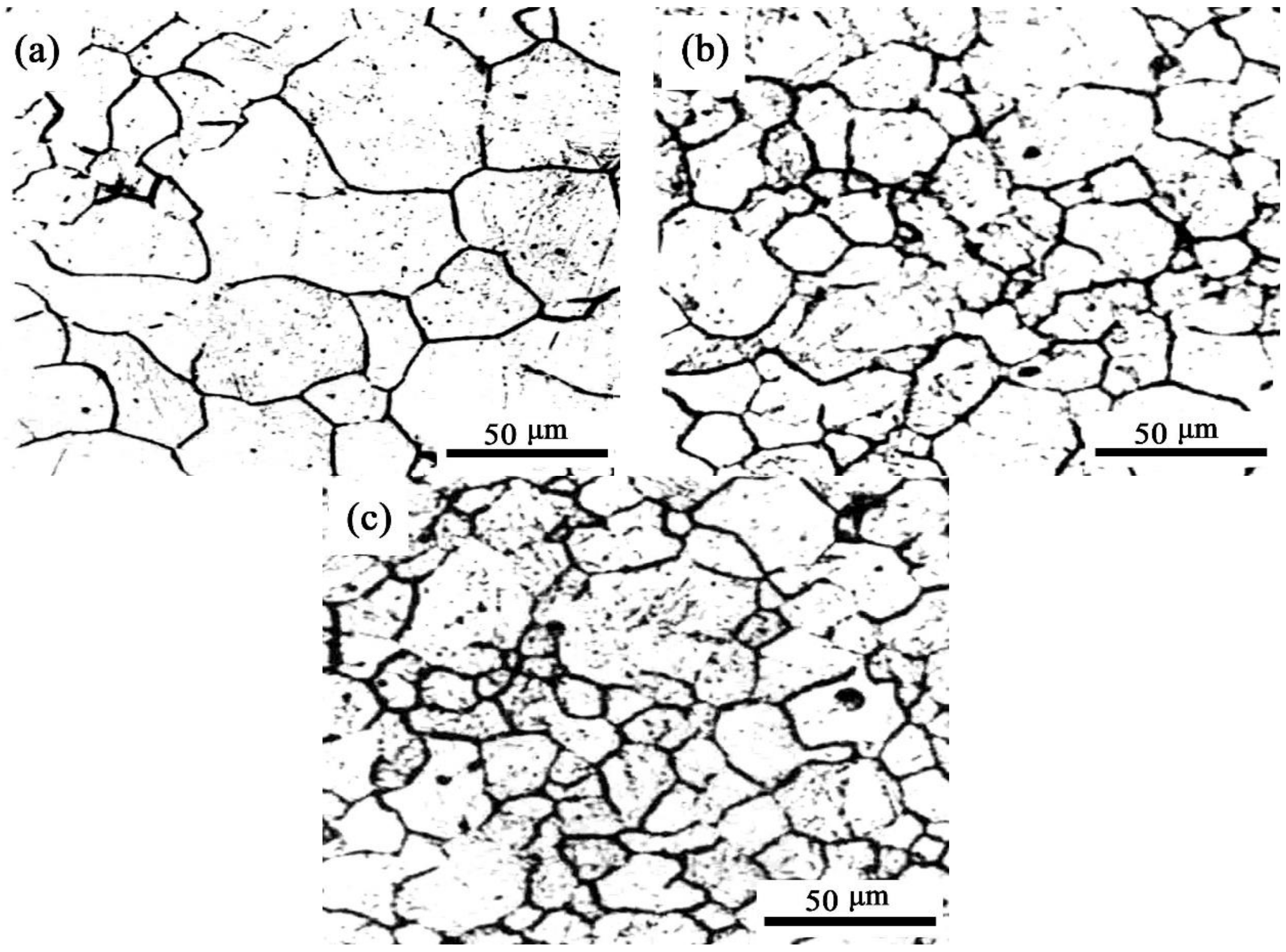
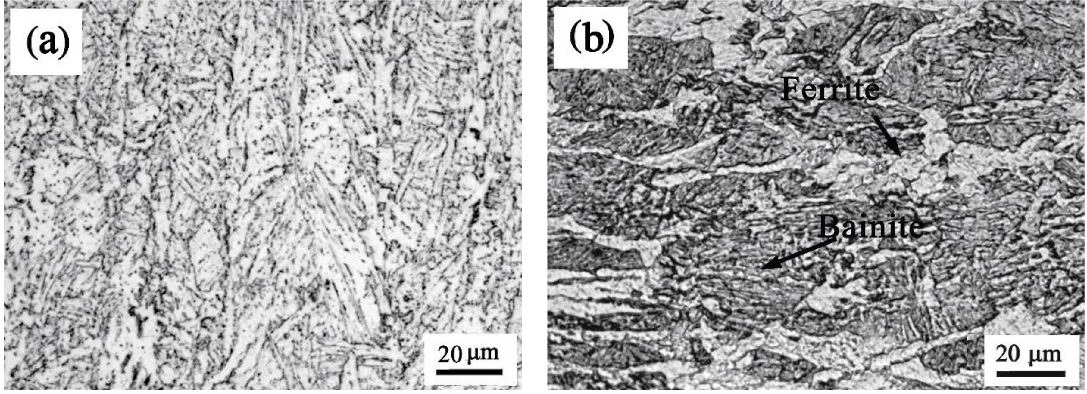
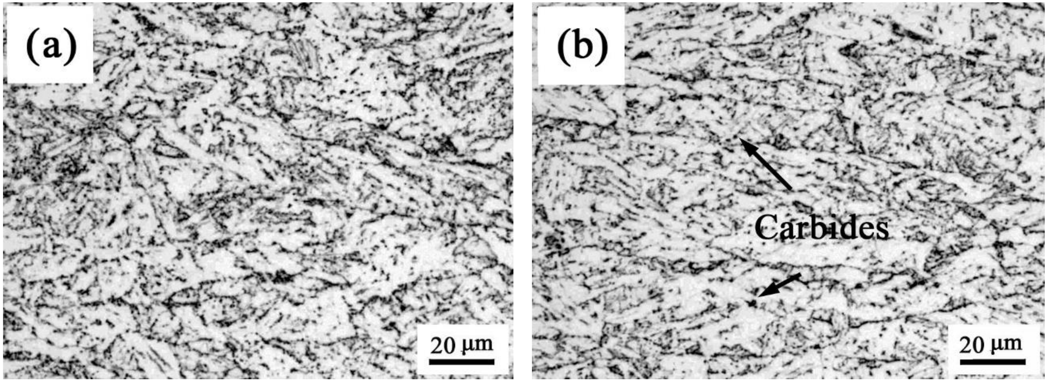
The CGHAZ microstructures of the samples #1, #2 and #3 are illustrated in Figure 4. It can be seen that the microstructure and morphology of the samples have changed greatly in contrast to the base metal, and the CGHAZ microstructures of the different microalloyed samples are significantly different. In Figure 4a, the microstructure is bainite along with a small amount of pearlite and carbide. In Figure 4b, the microstructure is bainite, polygonal ferrite and carbide. Figure 4c shows a uniform bainitic microstructure. In the process of welding thermal simulation, the peak temperature is high, the cooling rate and driving force of phase transformations are relatively small and there is no deformation induced effect, so the effects of Ti, Nb, and B microalloying elements on the microstructure and mechanical properties become more intense.
4. Discussion
4.1. Effect of Ti and Nb on the Microstructure of CGHAZ
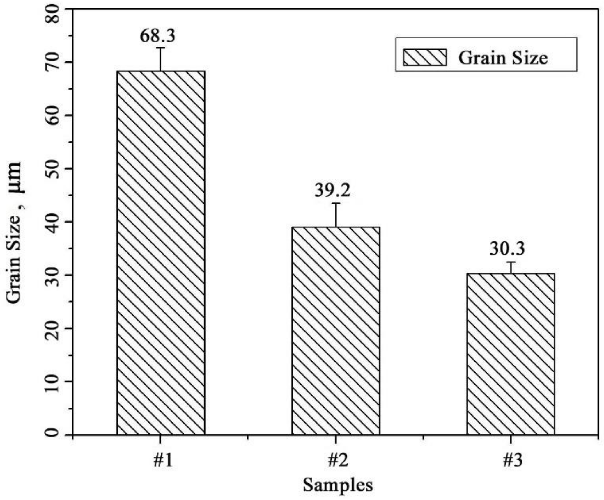
In contrast to sample #1, Ti and Nb were added to the chemical composition of sample #3. Under the same conditions, as shown in Figure 4a,c, Ti and Nb showed a significant influence on the microstructure type and refinement degree of CGHAZ. As shown in Figure 5, the grain size grades of CGHAZ austenite in samples #1, #2, and #3 were 4.5 ± 0.2, 7.5 ± 0.3 and 7.7 ± 0.3, respectively, and the grain size of CGHAZ austenite in samples containing Ti and Nb was found to be finer. The measured CGHAZ austenite grain size of three samples was shown in Figure 6.
The undissolved Ti and Nb carbonitride particles in the heating process effectively prevented the austenite grain growth by pinning the grain boundary. During the cooling process, the Ti and Nb carbonitride particles can increase the phase change nucleation point and prevent the grain boundary migration. Therefore, the addition of Ti, Nb alloy elements play a significant role in refining microstructure. Jha et al. [6] showed that a higher number of Ti, Nb carbonitride particles lead to a smaller size and more uniform distribution, and thus exert a more obvious effect on the refining of the microstructure.
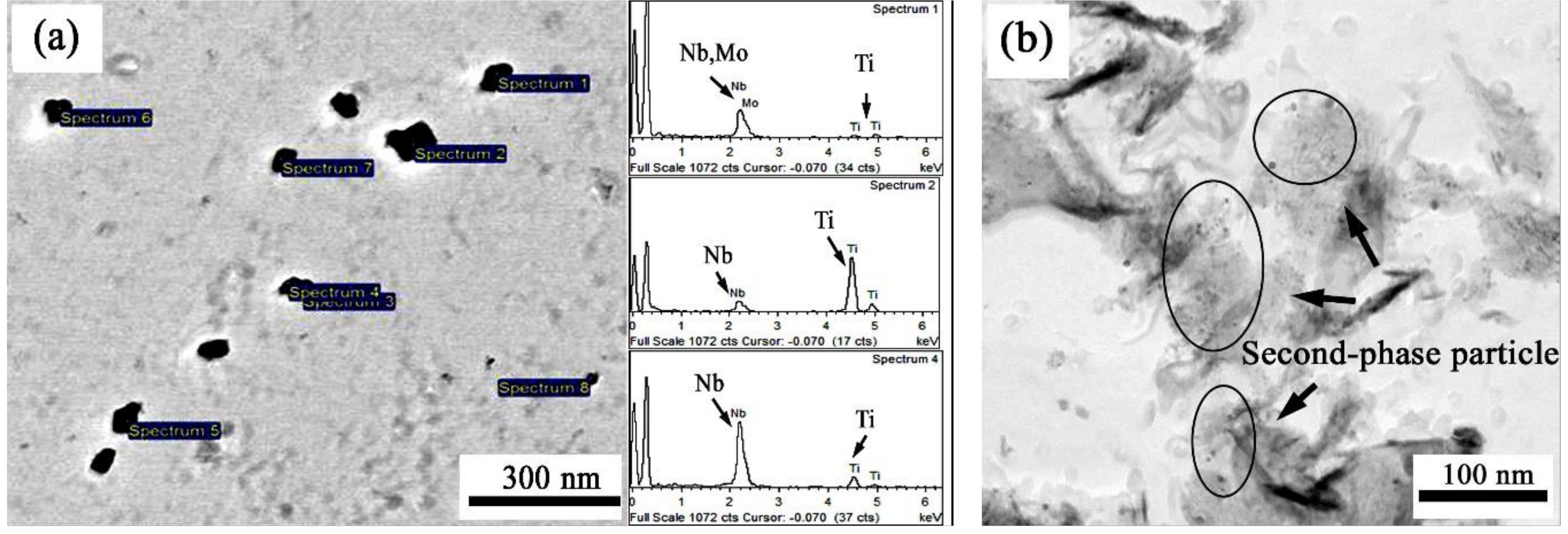
Figure 7 shows the morphology of the precipitate phase of base metal sample #3 under transmission electron microscope and its corresponding EDS spectrum. Sample was prepared by carbon membrane extraction replica method. It can be seen that there are a large number of second-phase particles with a small size and uniform distribution of the base metal, which are mainly spherical or ellipsoidal and less rectangular or irregular in shape. Spherical or ellipsoid precipitates are mainly (Nb, Ti) (CN), while rectangular or irregular precipitates are mainly (Ti, Nb) (CN). Some precipitated phases contain trace Mo, and the size of precipitated phases is in the range of 5–30 nm. Due to the addition of Ti, Nb, Mo, and other alloying elements in sample #3, under the influence of mixing entropy and deformation induction, the second phases always tend to be formed with more alloying elements rather than fewer alloying elements, and will be more uniform and fine, as the solid solubility of the alloying elements in the high-element second phase will decrease in the iron matrix compared with that of the same element in the low-element second phase [7].
In this study, CGHAZ was derived from the welding thermal simulation. The thermal cycle process is the process of re-austenization and solid phase transformation during the heating process of the base metal. The peak temperature of the thermal cycle Tp is 1320 °C, and the cooling time is t8/5 for 45 s. The cooling rate is about 6.7 °C/s. Due to the high re-austenitizing temperature, Ti and Nb carbonitride particles are easy to dissolve and mature, which affects the refinement of CGHAZ microstructure. Therefore, the dissolution and maturation of the second phase particles in the base metal during thermal cycling should be further studied.
In order to avoid the formation of large-sized nitrides in samples, the content of N was kept very low relative to that of C. N first binds with Ti to form TiN, and then forms carbides. Therefore, it is necessary to first consider the dissolution of the binary second phase such as TiN, alloying element carbide, etc., during heating. The solid solubility limit of TiN, TiC, NbC and MoC in austenite can be calculated by the following formulas [8]:
log{[Ti][N]}γ = 0.32–8000/T
log{[Ti][C]}γ = 2.75–7000/T
log{[Nb][C]}γ = 2.96–7510/T
log{[Mo][C]}γ = 1.29–523/T
log[C]γ = 1.36–1480/T (FeC3 in γ-iron)
In the formulas, [M] (M = Ti, Nb, Mo, C, N) is the solid solution amount of M element in austenite; gamma represents austenite; T is the temperature of the solid solution, in Kelvin (K). Firstly, the solution temperature (TAS) of carbides or nitrides can be calculated from the formulas. The TAS of TiN is 1611.5 °C, and those of other precipitates are all lower than the peak temperature of 1320 °C. When the precipitate of TiN is in ideal stoichiometric proportion (1:1), [Ti] and [N] can be calculated as 0.0177 and 0.00112 at 1320 °C. Then, we can calculate the molar fraction of TiN in the metal at 1320 °C, by the following formula:
fTiN=(Ti-[Ti]+N-[N]) (dFe/100dTiN)
In the formula, Ti and N are the molar fraction in steel, [Ti] and [N] are the solid solubility, dFe and dTiN are the density of steel and TiN, respectively. According to the formula calculation, at the peak temperature of 1320 °C, the molar fraction of TiN is 0.0125%, while the carbides of Fe, Nb, and Mo are dissolved.
As mentioned above, the solid solubility of the corresponding elements in the multicomponent second phase in the iron matrix decreases compared with that in the low-component second phase, and the second phase tends to form higher elements without forming multiple low-component second phases. Therefore, according to the solid solubility theory of multicomponent second phase [9], the number of undissolved multi-component second phase particles at 1320 °C is much larger than that of the theoretically calculated binary second phase, and exists mainly in the form of carbonitrides of spherical Ti [10].
The degree of maturation of insoluble particles is further considered. The results show that Ostwald ripening is mainly controlled by the diffusion of solute elements and the interfacial reaction at large particles [11]. Ti is a substitution solid solution element with high diffusion activation energy and high C content, which reduces Ti activity. Therefore, Ti diffusion rate in the matrix is slower than C and N, and it is the controlling element of maturation degree [12]. Moreover, the carbonitride of Ti has a semi-coherent relationship with austenite and contains higher interface energy. The results of Paju et al. [13] showed that the second phase particles can reach equilibrium maturation size at a high temperature if kept for a long time, but it is difficult for Ti carbonitrides to mature due to the short holding time at the high temperature during the thermal cycle. Therefore, in the process of welding thermal simulation, there are still a large number of fine second phase particles in samples #2 and #3 containing Ti and Nb at a high temperature, which can effectively refine the grain and microstructure of CGHAZ.
In addition to the above effects on grain refinement and microstructure refinement, Ti and Nb also have some effects on the structure type. According to the theory of solid-state transformation [14], diffusion of C and other alloying elements exists during bainite transformation, while Ti and Nb cause a decrease in the activity of C and inhibit the diffusion of C atoms [15]. In the thermal cycle cooling stage of sample #1 without Ti and Nb, the C atoms can easily diffuse to grain boundaries to agglomerate and grow carbides or to form carbon-rich regions. Pearlite are formed when the temperature reach the eutectoid transition point in this region.
4.2. Effect of Boron on the Microstructure of CGHAZ
In the process of microstructure transformation, boron is adsorbed on the grain boundary, filled with defects, reduces the energy level of grain boundary, inhibits the formation of pre-eutectoid ferrite during austenite cooling, prolongs the incubation period of austenite transformation, and improves hardenability. However, if boron and other interacting elements are not effectively controlled, boride is formed at grain boundaries, which might cause a negative impact, such as nitrogen could easily combine with boron. Therefore, in order to ensure the hardenability of boron, strong nitride forming elements (such as Ti, Al) are usually added to steel to reduce the negative effect of nitrogen on boron by "fixing nitrogen and protecting boron".
The interaction of N, B, and Ti can be expressed by effective B (Beffective) and excess Ti (Tiexcess). Some studies have shown that when effective B is controlled from 0.002% to 0.003%, the hardenability can be best improved [16].
The calculation of effective B refers to the empirical formula proposed by Kapadia [17]:
Beffective = B − [(N − 0.002) − Ti/5]
In the formula, B, N, and Ti are the total addition of each element, and 0.002 is the amount of N fixed by considering Al and Si in the steel.
When there is an excess of Ti in the steel, Ti fixes all N in the steel, and effective B is the total amount of B added. Empirical formulas are used to calculate excess Ti:
Tiexcess = Ti − [5 (N − 0.003)]
In the formula, N and Ti are the total amounts of each element added.
From the sample composition and CGHAZ microstructures (see Figure 4 above), it can be seen that the effective B content calculated by formula (6) is 0.0008% without Ti added to sample #1, which can improve hardenability and avoid the transformation of pre-eutectoid ferrite but most of B will precipitate as boride. No B was added to sample #2, so the ferrite transformation area was enlarged, resulting in a small block of the ferrite structure. After adding B and 0.07% Ti to sample #3, the outcome of formula (7) indicates that there is an excess of Ti in steel. Effective B is the total amount of added B, which is 0.0028%. Therefore, the hardenability is stronger than that of sample 1# and uniform bainite structure is obtained.
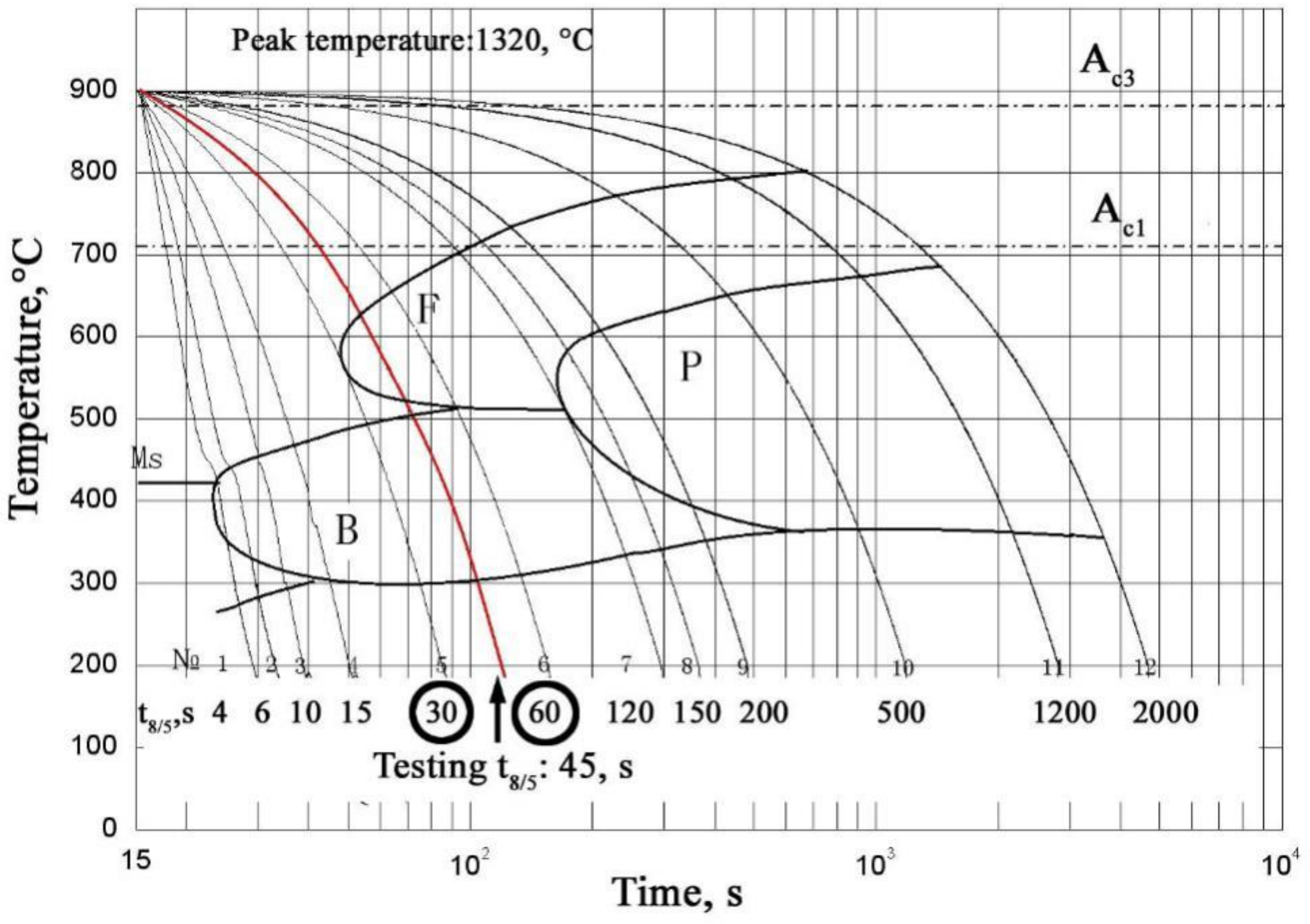
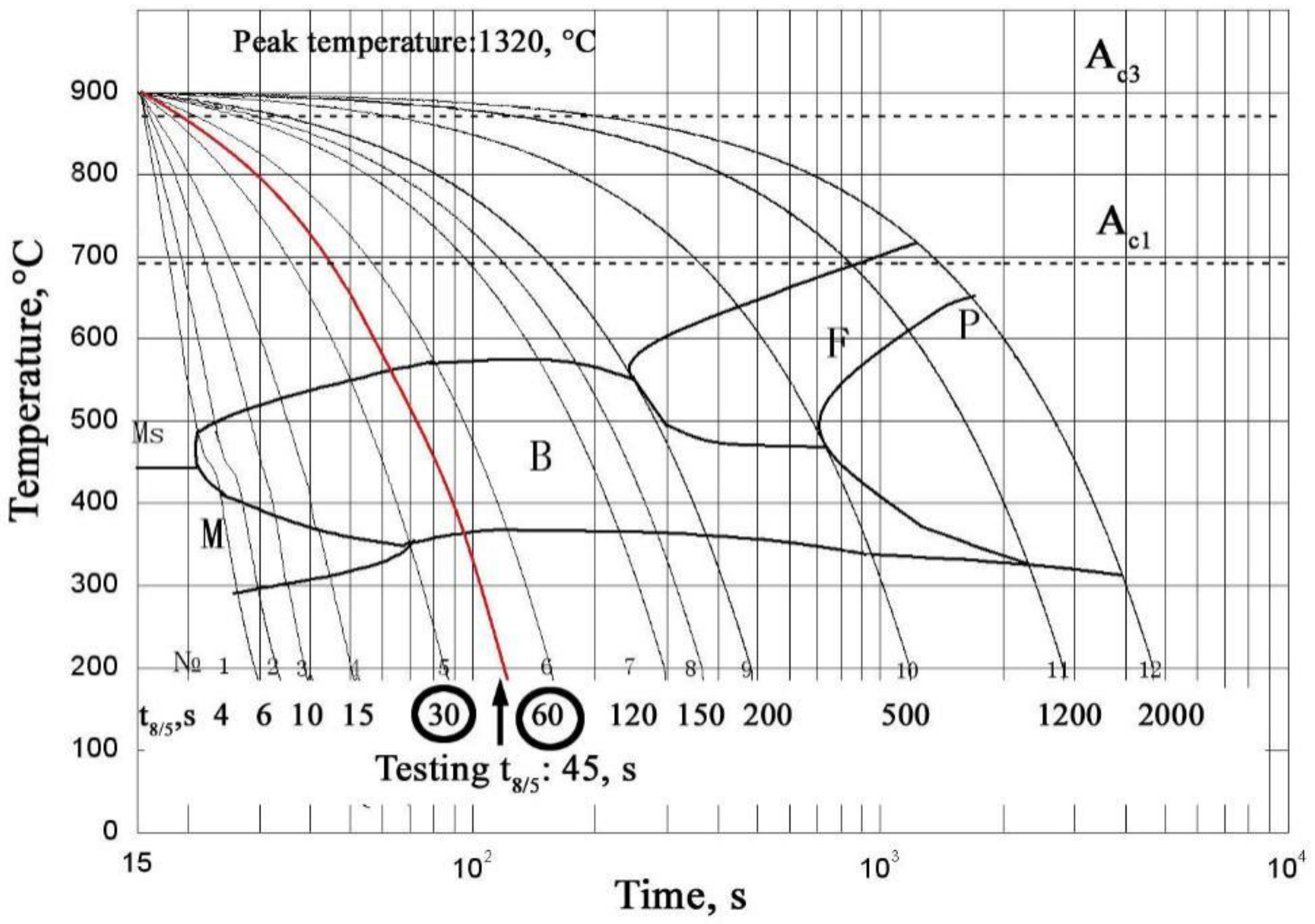
In order to certify the effect of boron on microstructure transformation, the welding CCT curves of the #2 and #3 samples are shown in Figure 8 and Figure 9, respectively. By using the same method as in Table 2, the t8/5 are from 4 s to 2000 s. We can find that the addition of boron moves the regions of ferrite and pearlite to the right, especially the region of ferrite.
Meanwhile, when the t8/5 is close to 45 s at the welding CCT curves, the micrographs of #2 and #3 are presented in Figure 10 and Figure 11.
It is seen that in Figure 10a and 10b that the microstructures are the bainite and ferrite+bainite respectively. The red cooling curve represents the thermal cycle cooling process of sample #2, and the t8/5 is about 45 s between 30 s and 60 s, the microstructure is ferrite+bainite, as shown in Figure 4b. In Figure 11, it is seen that the microstructure is bainite. The red cooling curve represents the thermal cycle cooling process of sample #3, and the microstructure is also bainite, as shown in Figure 4c. The microstructure transformation during the cooling process is consistent with the previous experimental result.
4.3. Effect of CGHAZ Microstructure on Brittleness
From the test results shown in Table 3 and Table 4, the hardness and impact toughness are compared in Figure 12, it can be seen that the decrease in the CGHAZ impact toughness of three kinds of high hardness and high impact toughness samples after welding thermal cycle is much larger than that of hardness. Thus it can be said that different compositions of microalloying mainly affect the brittleness resistance of wear-resistant steel CGHAZ. According to a study [18], the brittleness of low-alloy wear-resistant steel CGHAZ is mainly due to the coarse grain embrittlement and microstructural embrittlement [19].
There is a linear quantitative relationship between the brittle transition temperature and grain size, which is the main parameter to measure the brittleness of bainitic and martensitic steels. The effect of grain size on brittleness usually satisfies the following equation:
VTrs = B − AD−1/2
In the formula, VTrs represents the brittle transition temperature, A and B are constants, D is the effective grain size.
As shown by the austenite grain size of CGHAZ (see Figure 6), the grain size of sample #1 without Nb and Ti became highly coarsened after thermal cycling, and the impact toughness was also significantly lower than that of samples #2 and #3. This indicates that coarse grain embrittlement is the main cause of CGHAZ embrittlement.
As shown in Figure 4, the microstructures of samples #1, #2 and #3 are different. The CGHAZ microstructures of the three samples were further analyzed by transmission electron microscopy. The CGHAZ microstructures of samples #1, #2, and #3 under TEM are shown in Figure 13, Figure 14 and Figure 15, respectively.
Figure 13 shows the CGHAZ microstructure of sample #1. It is seen that a large number of carbides are distributed in the bainite matrix and on the grain boundary. Carbides on the grain boundary form continuous chain-like particles. Figure 13b shows pearlite on the bainite grain boundary. The magnified image in Figure 13c shows carbide particles (about 0.5 μm in length), dislocation accumulation can also be seen in the matrix.
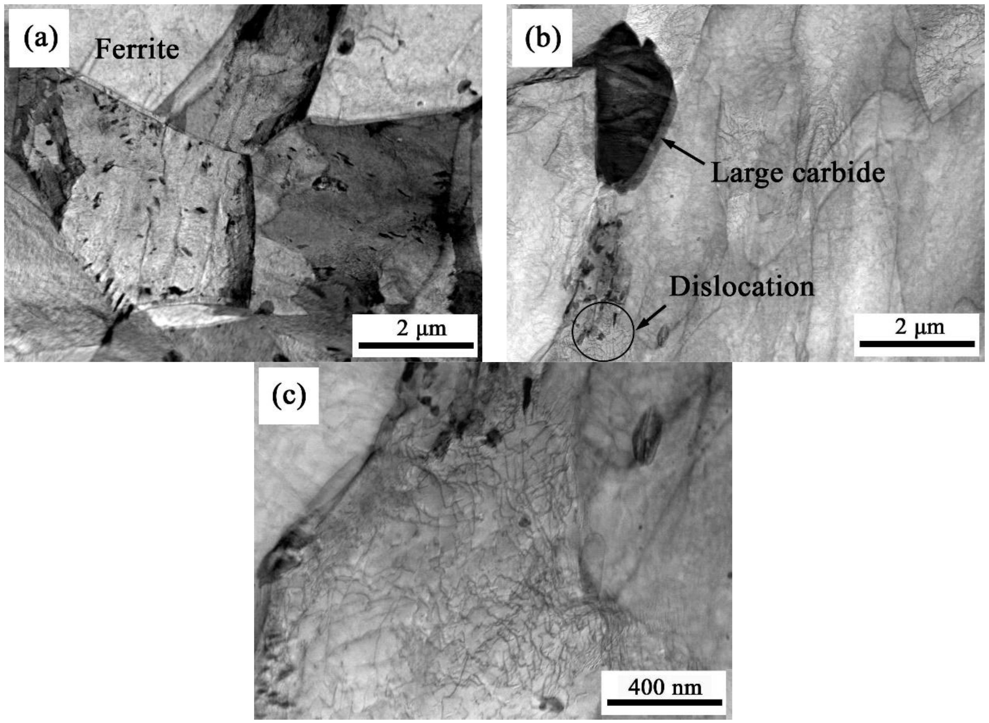
Figure 14 is the CGHAZ microstructures of sample #2. Figure 14a,b show that there are small blocks of ferrite and large particles of carbide (about 2.1 μm in length) at the grain boundary of bainite, and a large number of fine carbides and Nb and Ti precipitates on the bainite matrix. Partially enlarged Figure 14c shows a large number of dislocations plugging on the matrix near the large particles of carbide.
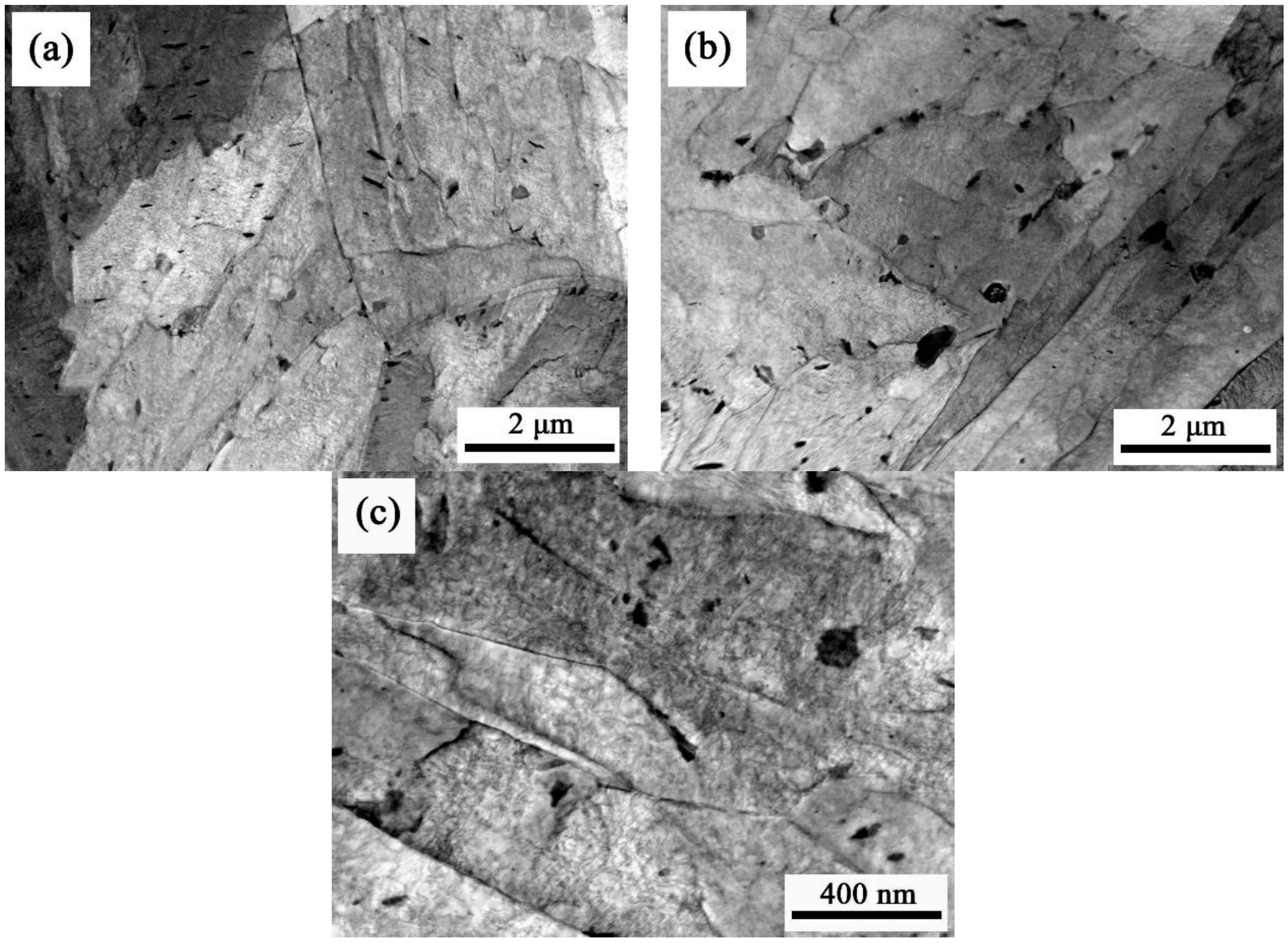
Figure 15 shows the CGHAZ microstructures of sample #3. Figure 15a,b show that the bainite microstructure is uniform with a large number of carbides, of which the largest one is about 0.6 μm and smaller than that of samples #1 and #2, Nb-Ti precipitates are distributed on the matrix without large particles. Partially enlarged Figure 15c shows that dislocation plugging on the matrix is not obvious.
According to the analysis of the above two sections, the difference in the CGHAZ microstructures of the three samples is mainly related to the microalloying composition of Nb, Ti, and B. There is a small amount of effective B in sample #1, and most of the B and other alloys collectively grow at the grain boundary in the form of a compound to weaken the grain boundary. Due to the insufficient hardenability, at the same time as bainite transformation, C diffuses to the grain boundary and enriches and pearlite transforms, which together with large particle carbides causes matrix dislocations, resulting in the local stress concentration. Finally, the grain boundary weakening and local stress concentration lead to brittleness. The non-addition of B to sample #2 resulted in the worst austenite stability and ferrite transformation. The C-rich region where C diffuses to the vicinity of the ferrite forms large-grain carbides and causes matrix dislocations to be accumulated, resulting in local stress concentration. The resulting small piece of ferrite also weakens the grain boundaries. Finally, the local stress concentration and weakening of the grain boundaries lead to brittleness. Sample #3 was added with alloying elements such as Ti, Nb, and B, and the added B was all effective B, which made the sample to have the best hardenability and the resulting bainite structure was more uniform. Ti and Nb lower the activity of C, making the carbide and precipitate phase finer. Finally, the uniform bainite microstructure is generated and the formation of a large particle hard phase is avoided, which can effectively reduce the embrittlement of the structure. In summary, different compositions of microalloying resulted in different types of microstructures. The CGHAZ microstructures of B and Ti-Nb microalloyed wear-resistant steels have poor uniformity, which weakens grain boundaries and leads to the brittleness of microstructures.
5. Conclusions
- (1)
- B, Ti-Nb, and Ti-Nb-B microalloyed C-Mn-Si-Mo wear-resistant steels with high hardness and good impact toughness can be treated by CR + DQ + T process. Since the M/B dual-phase microstructure is obtained, and the effective grains are fully refined.
- (2)
- When the heat input is 20 kJ/cm, the impact toughness of B, Ti-Nb, Ti-Nb-B microalloyed wear-resistant steel CGHAZ decreases by 75.9%, 35.4%, and 15.1%, respectively, compared with the base metal. Coarsened grain during welding thermal cycle is the main reason, and the abnormal structure on grain boundaries increases the tendency of embrittlement.
- (3)
- Ti-Nb-B compound microalloying can reduce the degree of embrittlement of CGHAZ since undissolved Nb-Ti second-phase particles can prevent grains from coarsening. The dissolved boron (Beffective) can improve hardenability by avoiding perlitic and ferritic transformation during the cooling process and improve the uniformity of bainitic microstructure.
Author Contributions
Conceptualization, K.W.; methodology, D.L.; software, O.I.; validation, D.L., H.D. and K.W.; formal analysis, D.L. and H.D.; investigation, D.L.; resources, O.H.; data curation, O.H.; writing—original draft preparation, D.L. and H.D.; writing—review and editing, K.W. and H.D.; visualization, D.L. and H.D.; supervision, K.W.; project administration, K.W.; funding acquisition, K.W.
Funding
This research was funded by [Major Technology Innovation of Hubei Province] grant number [2016AAA022], [Natural Science Foundation of Hubei Province] grant number [2016CFA004] and the 111 Project.
Conflicts of Interest
The authors declare no conflict of interest.
References
- Gao, Z.; Niu, J. Study on microstucture and impact ductility of simulated weld HAZ of high-strength wear-resistant steel NM360. Rev. Adv. Mater. Sci. 2013, 33, 232–237. [Google Scholar]
- Dudziński, W.; Konat, L.; Pekalski, G. Structural and strength characteristics of wear-resistant martensitic steels. Arch. Foundry Eng. 2008, 8, 21–26. [Google Scholar]
- Graville, B.A. Cold cracking in welds in HSLA steels. In Proceedings of the International Conference of Welding in HSLA Micro-alloyed Structural Steels, Rome, Italy, 9–12 November 1976; pp. 85–101. [Google Scholar]
- Dhua, S.K.; Mukerjee, D.; Sarma, D.S. Influence of thermomechanical treatments on the microstructure and mechanical properties of HSLA-100 steel plates. Metall. Mater. Trans. A 2003, 34A, 241–253. [Google Scholar] [CrossRef]
- Yang, X.; Zhang, L.; Shi, Y.; Yu, S.; Dong, C.; Hua, W.; Li, X. Effective microstructure unit in control of impact toughness in CGHAZ for high strength bridge steel. J. Wuhan Univ. Technol. Mater. Sci. Ed. 2018, 33, 177–184. [Google Scholar] [CrossRef]
- Jha, G.; Das, S.; Sinha, S.; Lodh, A.; Halder, A. Design and development of precipitate strengthened advanced high strength steel for automotive application. Mater. Sci. Eng. 2013, A561, 394–402. [Google Scholar] [CrossRef]
- Funakawa, Y. Mechanical properties of ultra fine particle dispersion strengthened ferritic steel. Mater. Sci. Forum Trans. Tech. 2012, 706–709, 2096–2100. [Google Scholar] [CrossRef]
- Yong, Q.L. Secondary Phase in Steels; Metallurgical Industry Press: Beijing, China, 2006; pp. 361–372. ISBN 7-5024-4000-3. [Google Scholar]
- Mao, X.P.; Chen, Q.L.; Sun, X.J. Metallurgical interpretation on grain refinement and synergistic effect of Mn and Ti in Ti-microalloyed strip produced by TSCR. J. Iron Steel Res. Int. 2014, 21, 30–40. [Google Scholar] [CrossRef]
- Kestenbach, H.J.; Camposm, S.S.; Morales, E.V. Role of interphase precipitation in microalloyed hot strip steels. Mater. Sci. Technol. 2006, 22, 615–626. [Google Scholar] [CrossRef]
- Yang, G.-W.; Sun, X.-J.; Yong, Q.-L.; Li, Z.-D.; Li, X.-X. Austenite grain refinement and isothermal growth behavior in a low carbon vanadium microalloyed steel. J. Iron Steel Res. Int. 2014, 21, 757–764. [Google Scholar] [CrossRef]
- Funakawa, Y.; Shiozaki, T.; Tomita, K.; Yamamoto, T.; Maeda, E. Development of high strength hot-rolled sheet steel consisting of ferrite and nanometer sized carbides. ISIJ Int. 2004, 44, 1945–1951. [Google Scholar] [CrossRef]
- Jang, J.H.; Heo, Y.U.; Lee, C.H.; Bhadeshia, H.K.D.H.; Suh, D.W. Interphase precipitation in Ti-Nb and Ti- Nb-Mo bearing steel. Mater. Sci. Technol. 2013, 29, 309–313. [Google Scholar] [CrossRef]
- Mecozzi, M.G.; Sietsma, J.; van der Zwaag, S. Analysis of γ→α transformation in a Nb micro-alloyed C-Mn steel by phase field modeling. Acta Mater. 2006, 54, 1431–1440. [Google Scholar] [CrossRef]
- Wang, H.H.; Qin, Z.P.; Wan, X.L.; Wei, R.; Wu, K.M.; Misra, D. Continuous cooling transformation behavior and impact toughness in heat-affected zone of Nb-containing fire-resistant steel. Met. Mater. Int. 2017, 23, 848–854. [Google Scholar] [CrossRef]
- Li, L.; Han, T.; Han, B. Embrittlement of intercritically reheated coarse grain heat-affected zone of ASTM4130 steel. Metall. Mater. Trans. A 2018, 49, 1254–1263. [Google Scholar] [CrossRef]
- Poorhaydari, K.; Ivey, D.G. Heat-affected zone property diagrams for a grade 100 microalloyed steel. Weld. World 2018, 62, 551–564. [Google Scholar] [CrossRef]
- Ghosh, A.; Das, S.; Chatterjee, S. Ageing behavior of a Cu-bearing ultrahigh strength steel. Mater. Sci. Eng. 2008, 486A, 152–157. [Google Scholar] [CrossRef]
- Song, H.; Li, C.; Lan, L.; Zhao, D.; Wang, G. Impact toughness of an NM400 wear-resistant steel. J. Iron Steel Res. Int. 2013, 20, 72–77. [Google Scholar] [CrossRef]
Figure 1.
CR + DQ + T process.

Figure 2.
SEM micrographs of one of the three samples after DQ.

Figure 3.
SEM micrographs of (a) sample #1, (b) sample #2, and (c) sample #3.

Figure 4.
CGHAZ micrographs of (a) sample #1 (Bainite + pearlite), (b) sample #2 (Bainite + ferrite), and (c) sample #3 (Bainite).
Figure 4.
CGHAZ micrographs of (a) sample #1 (Bainite + pearlite), (b) sample #2 (Bainite + ferrite), and (c) sample #3 (Bainite).

Figure 5.
CGHAZ austenite grain boundary of (a) sample #1, (b) sample #2, and (c) sample #3.

Figure 6.
Measured CGHAZ austenite grain size of three samples.

Figure 7.
Precipitate phase of base material of Ti-Nb microalloyed samples.

Figure 8.
Welding CCT curve of #2 sample.

Figure 9.
Welding CCT curve of #3 sample.

Figure 10.
The microstructues of sample #2 cooled by t8/5 (a) 30 s and (b) 60 s, respectively.

Figure 11.
The microstructues of sample #3 cooled by t8/5 (a) 30 s and (b) 60 s, respectively.

Figure 12.
Compared hardness (a) and impact toughness (b) before and after welding thermal cycle.

Figure 13.
TEM micrograph (a), (b) and (c) showing the CGHAZ microstructure of sample #1; (c) is magnified photograph of circled region in (b).
Figure 13.
TEM micrograph (a), (b) and (c) showing the CGHAZ microstructure of sample #1; (c) is magnified photograph of circled region in (b).

Figure 14.
TEM micrograph (a), (b) and (c) showing the CGHAZ microstructure of sample #2; (c) is magnified photograph of circled region in (b).
Figure 14.
TEM micrograph (a), (b) and (c) showing the CGHAZ microstructure of sample #2; (c) is magnified photograph of circled region in (b).

Figure 15.
TEM micrograph (a), (b) and (c) showing the CGHAZ microstructure of sample #3.


Table 1.
Chemical composition of the investigated steel samples, wt%.
| Samples | C | Mn | Si | P | S | Mo | B | Al | Ti | Nb | N |
|---|---|---|---|---|---|---|---|---|---|---|---|
| #1 | 0.239 | 1.402 | 0.223 | 0.008 | 0.002 | 0.407 | 0.0028 | 0.033 | - | - | 0.0045 |
| #2 | 0.241 | 1.398 | 0.219 | 0.007 | 0.003 | 0.402 | - | 0.034 | 0.067 | 0.023 | 0.0043 |
| #3 | 0.238 | 1.403 | 0.221 | 0.008 | 0.002 | 0.405 | 0.0027 | 0.033 | 0.064 | 0.021 | 0.0046 |
Table 2.
Single-pass welding thermal simulation process.
| Heating Rate, °C/s | Peak Temperature, °C | Peak Temperature Holding Time, s | Cooling Time, s | Cooling Rate, °C/s | Heat Input, kJ/cm |
|---|---|---|---|---|---|
| 100 | 1320 | 1 | 45 | 6.7 | 20 |
Table 3.
The mechanical properties of the base metal.
| Samples | Hardness | Impact Toughness | ||||||
|---|---|---|---|---|---|---|---|---|
| HBW10/3000 | Akv (20 °C), J | |||||||
| No. 1 | No. 2 | No. 3 | Average | No. 1 | No. 2 | No. 3 | Average | |
| #1 | 486 | 489 | 483 | 486 ± 3.0 | 97 | 112 | 104 | 104 ± 7.5 |
| #2 | 489 | 488 | 495 | 491 ± 3.8 | 89 | 124 | 84 | 99 ± 21.8 |
| #3 | 495 | 498 | 492 | 495 ± 3.0 | 122 | 96 | 102 | 106 ± 13.6 |
Table 4.
Mechanical properties of CGHAZ.
| Samples | Hardness | Impact Toughness | ||||||
|---|---|---|---|---|---|---|---|---|
| HBW10/3000 | Akv (20 °C), J | |||||||
| No.1 | No.2 | No.3 | Average | No.1 | No.2 | No.3 | Average | |
| #1 | 345 | 343 | 350 | 346 ± 3.6 | 24 | 23 | 28 | 25 ± 2.6 |
| #2 | 361 | 368 | 363 | 364 ± 3.6 | 58 | 53 | 82 | 64 ± 15.5 |
| #3 | 384 | 380 | 389 | 384 ± 4.5 | 91 | 85 | 95 | 90 ± 5.0 |
© 2019 by the authors. Licensee MDPI, Basel, Switzerland. This article is an open access article distributed under the terms and conditions of the Creative Commons Attribution (CC BY) license (http://creativecommons.org/licenses/by/4.0/).
Share and Cite
MDPI and ACS Style
Li, D.; Wu, K.; Dong, H.; Isayev, O.; Hress, O. Coarse Grained Heat-Affected Zone Microstructure and Brittleness of Ti-Nb-B Microalloyed High Toughness and Wear Resistant Steel. Metals 2019, 9, 289. https://doi.org/10.3390/met9030289
AMA Style
Li D, Wu K, Dong H, Isayev O, Hress O. Coarse Grained Heat-Affected Zone Microstructure and Brittleness of Ti-Nb-B Microalloyed High Toughness and Wear Resistant Steel. Metals. 2019; 9(3):289. https://doi.org/10.3390/met9030289
Chicago/Turabian StyleLi, Defa, Kaiming Wu, Hangyu Dong, Oleg Isayev, and Oleksandr Hress. 2019. "Coarse Grained Heat-Affected Zone Microstructure and Brittleness of Ti-Nb-B Microalloyed High Toughness and Wear Resistant Steel" Metals 9, no. 3: 289. https://doi.org/10.3390/met9030289
Note that from the first issue of 2016, this journal uses article numbers instead of page numbers. See further details here.