Thermal Processing of Jarosite Leach Residue for a Safe Disposable Slag and Valuable Metals Recovery
by
 , , , and
Minna Rämä
1,* ,
,
Samu Nurmi
1,
Ari Jokilaakso
1,
Lassi Klemettinen
1,
Pekka Taskinen
1 and
Justin Salminen
2 1
Department of Chemical and Metallurgical Engineering, School of Chemical Engineering, Aalto University, Kemistintie 1, P.O. Box 16100, FI-00076 Aalto, Finland
2
Boliden Kokkola Oy, P.O. Box 26, 67101 Kokkola, Finland
*
Author to whom correspondence should be addressed.
Metals 2018, 8(10), 744; https://doi.org/10.3390/met8100744
Submission received: 4 September 2018
/
Revised: 19 September 2018
/
Accepted: 20 September 2018
/
Published: 21 September 2018
(This article belongs to the Special Issue Sustainable Utilization of Metals - Processing, Recovery and Recycling)
Abstract
:In electrolytic production of zinc, the iron levels in the solutions are controlled by precipitation of jarosite or goethite. These precipitates also co-precipitate unrecovered valuable metals (Zn, Pb, Cu, Ag) as well as elements of concern (As, Cd, Hg). After stabilization, the residues are traditionally landfilled. This work investigates pyrometallurgical treatment of jarosite residue to convert the material into reusable clean slag and to recover the valuable metals within the residue. The pyrometallurgical treatment is divided into two functional steps. First, the material is melted in an oxidizing atmosphere, after which the oxide melt is reduced to produce an inert, clean slag. Then, a liquid metal or speiss phase collects the valuable metals, such as silver. The aim was to examine the optimal process conditions for reaching the target values for remaining metals in the slag; Pb < 0.03 wt %, Zn < 1 wt %. As a conclusion, the limiting factor in sulfur, lead, and zinc removal is the contact between the oxidizing or reducing gas and the molten sample. The mass transfer and volatile metals removal were significantly improved with a gas lance installation. The improved gas-liquid interaction enabled the first steps of gas flow rate optimization and ensured the sufficiently low end-concentrations of the aforementioned elements.
1. Introduction
Approximately 85% of zinc worldwide is currently produced via RLE (Roasting-Leaching-Electrowinning) processes, which generate 0.5‒0.9 tonnes of dry jarosite residue for every tonne of zinc produced, as iron level in the leaching solution is controlled by precipitation [1,2,3]. The iron precipitation is also possible by producing goethite, paragoethite, or hematite; however, the jarosite process is used most commonly worldwide [4]. The chemical formula of jarosite is ZFe3(SO4)2(OH)6, where Z represents either Ag+, H3O+, K+, Li+, Na+, NH4+, or ½ Pb2+ [5]. On an industrial scale, typical cations used for precipitation are Na+, K+, and NH4+. Jarosite leach residues may also contain unrecovered base metals (Zn, Pb, Cu), critical elements (In, Ga, Ge, Sb), precious metals (Ag and Au), and elements of concern (As, Cd, Hg) [2,6,7]. These iron-rich leach residues are not suitable for use because of their classification as hazardous waste due to the heavy metals they contain [8].
Landfilling of iron rich sludge is still allowed in many countries; hence, stockpiling the waste is still commonly practiced [2]. However, the overall goal to improve yields and resource efficiency, legislative matters, as well as the aim towards a circular economy have increased the interest in processing these residues into a usable form. The goal is to produce an inert slag that could be used for construction purposes and, simultaneously, to recover the valuable metals from the residue [9,10]. Some production sites have already started to treat the generated residues with different pyrometallurgical technologies [2,11,12].
Several driving forces for process development, including both economic and environmental aspects, have been recognized. First of all, large amounts of already stockpiled or continuously produced iron-rich residues could be utilized, for example in road building or other construction material applications, instead of being disposed of [11,13]. The availability of land for this kind of hazardous waste landfilling is also limited, and causes additional costs [10,13,14]. In addition, recycling of the valuable metals within the residues is hindered due to the present practice, which results in these metals ending up in the landfills. However, the global aim for more efficient utilization of natural resources necessitates the use of residues as secondary raw material sources [2,10].
Pyrometallurgical treatment of jarosite leach residue has proved to be the most promising processing route due to its ability to both produce a clean slag and to recover most of the valuable metals. However, more detailed knowledge of the processing possibilities, as well as the effects of different processing parameters and variables, are required for process development and optimization.
A computational equilibrium model [15] created with MTDATA software (National Physical Laboratory, Teddington, UK) [16] and Mtox database (Version 8.2) [17] was used to do a preliminary scope for suitable conditions for the thermal treatment of jarosite residue. The model [15], earlier studies [18], and industrial processes [12] have proved that the pyrometallurgical treatment of this kind of residue can be divided into two functional steps. The first step of the treatment is conducted under oxidizing conditions to thermally decompose the material, releasing the sulfates and OH-groups, and to melt the material. During the second step, the formed oxide melt is reduced and the volatile elements are removed to the gas phase. Thereby, a clean slag and a liquid metal alloy are formed. The formation of the metal alloy during the reduction stage plays an important role due to its ability to collect various low-concentration metals from the material, such as Ag, As, and Sb [19].
High-temperature (1400 °C) experiments were conducted in a laboratory with industrial jarosite samples to investigate how to convert the jarosite residue into a clean (Pb < 0.03 wt %, Zn < 1 wt %) and inert slag product and to determine in what conditions the volatile metals and elements are extracted from the residue. The pyrometallurgical treatment in laboratory-scale showed that the targets can be reached with selected process conditions [20]. However, due to the low sample masses in the earlier study, it was not possible to conduct detailed elemental analyses for the samples. Thus, in this work, larger sample sizes will be used, allowing full chemical analysis to be performed as well. Different process parameter (treatment time, gas flow rates, gas lance/no gas lance) values were tested to determine the optimal conditions for reaching the targeted results.
The microstructures and phase compositions were determined using a scanning electron microscope equipped with an energy dispersive spectrometer (SEM-EDS). The inductively coupled plasma-optical emission spectroscopy (ICP-OES) method was used to determine the chemical composition of the bulk samples.
2. Materials and Methods
High-temperature (1400 °C) laboratory-scale experiments were conducted with industrial jarosite samples (about 15 wt % Fe, 4 wt % Zn, and 3 wt % Pb). The exact initial composition of the test material is omitted, and it may also have some variation due to the heterogeneous nature of industrial residue.
The test material was dried at 80 °C for 18 h to reduce its moisture content. After drying, the material was homogenized by grinding it manually in a mortar. Pre-treatment of the material was conducted at 700 °C for 15 min in air (65 mL/min) to release some of the OH-groups and sulfates by thermal decomposition. Several batches of pre-treatments were mixed to obtain a homogenous material for the experiments. The measured mass losses obtained in the pre-treatments were compared to previous TGA (thermogravimetric analysis) measurements [15] to verify the sufficiency of the treatment.
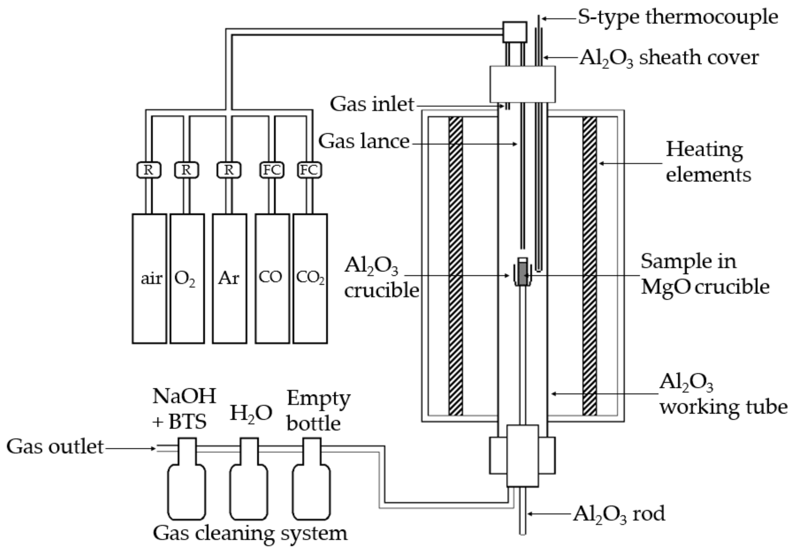
Figure 1 shows a schematic of the experimental arrangement. Pre-treatments as well as oxidation and oxidation-reduction experiments were all conducted in a vertical tube furnace (LTF 16/-/450, Lenton, Nottingham, UK) equipped with an alumina working tube (impervious pure alumina, 45/38 mm OD/ID). Temperature was monitored with a calibrated Pt/Pt10Rh thermocouple (Johnson Matthey, London, UK, uncertainty ± 3 °C) inside an alumina sheath, connected to multimeters (models 2000 and 2010, Keithley, Solon, OH, USA). Experimental gases (air: 80% N2, purity 5.0 and 20% O2, purity 5.0, O2: purity 5.0, Ar: purity 5.0, CO: purity 3.7, CO2: purity 5.3, all from AGA Linde, Riihimäki, Finland) were injected from the top of the furnace either into the working tube or directly onto the sample through an alumina rod acting as a gas lance (3 mm ID), see Figure 1. Either rotameters (air, O2, Ar; Kytola Instruments, Muurame, Finland) or mass flow controllers (CO, CO2; Aalborg DFC26, USA) were used for regulating the gas flow rates.
A gas cleaning system connected to the furnace ensured the safe neutralization or recovery of the off-gases and volatilized elements. An underpressure pump (LabVac LVH40, Piab, Sweden) enhanced the gas outflow from the furnace into the gas cleaning system. The first bottle of the system was empty and was used to prevent the escape of the liquids into the furnace in case of a blockage in the gas train. The second and third bottles contained H2O and a NaOH solution (6.5 M, 98% NaOH pellets from J.T.Baker, Phillipsburg, NJ, USA), respectively. BTS indicator (Bromothymol blue, C27H28Br2O5S, Sigma-Aldrich, St. Louis, MO, USA) was dissolved into the NaOH solution to indicate the point where NaOH was consumed from the scrubber solution.
The test material was held in dense MgO crucibles (SC10030, 20/75 mm ID/H, Tateho Ozark Technical Ceramics, Webb City, MO, USA) during the pre-treatments and experiments. The sample was introduced into the hot zone of the furnace by elevating the alumina rod entering the furnace through a leak-proof plug at the bottom of the furnace. The sample was lifted to the hot zone under inert atmosphere (argon) gradually to prevent possible cracking of the crucible, after which the atmosphere was changed to oxidizing. After an oxidation experiment, the atmosphere was changed back to inert, and the sample was lowered to the colder section of the furnace for cooling. In the oxidation-reduction experiments, the atmosphere was directly changed from oxidizing to reducing, and again back to inert after the reduction stage was completed, followed by lowering of the sample for cooling.
Table 1 shows the experimental parameters used in the experiments. All the experiments were conducted at 1400 °C, as that temperature was previously shown to be required for melting the test material with smaller samples [20]. The target was to investigate the optimal conditions for reaching the desired results and, furthermore, how to enhance the process, for example, by adding a gas lance to the experimental arrangement.
The first oxidation experiments (O1 and O2) conducted with 65 mL/min oxygen flow rate (STP) were for testing if 30 or 60 min treating time is needed for efficient sulfur removal. Based on the analysis results, the next experiments (O3 and O4) were conducted with doubled and quadrupled oxygen flow rates, respectively, to enhance the removal of sulfur from the material. The 60 min treating time was selected based on the results, which showed that 30 min treating time is not enough for sulfur removal. For the experiments O5 and O6, an oxygen gas lance straight above the sample was used to enhance the contact between oxygen and the sample and, thus, to perform the oxidation stage faster and with less oxygen.
Desulfurization during the oxidation stage occurs when sulfur in the material combusts and sulfur dioxide gas is formed as follows:
S + O2 (g) → SO2 (g)
Based on this reaction, the theoretical need of oxygen for complete sulfur removal was calculated. The 30 min experiments O1 and O5, conducted with oxygen flow rate of 65 mL/min, were performed with the stoichiometric amount of oxygen. The 60 min experiments with the same oxygen flow rate (O2 and O6) had oxygen approximately 2 times the stoichiometric requirement. Experiments O3 and O4 had oxygen about 4 and 8 times the stoichiometric need, respectively. The oxidation stage of the oxidation-reduction experiments was conducted with about 4 times the amount of oxygen compared to the theoretical need in the experiments O-R1 and O-R3, and with about 8 times the amount of oxygen in the experiments O-R2 and O-R4. The ratio between the used and stoichiometrically needed oxygen in each experiment can be expressed as O2 excess factor, and its effect on the sulfur removal efficiency during the oxidation experiments was investigated.
Oxidation time of 60 min and temperature of 1400 °C were used in all oxidation-reduction experiments. Based on the analysis results of the oxidation experiments, the oxidation stage in these experiments was selected to be conducted with two different oxygen flow rates; 130 and 260 mL/min (O-R1 and O-R2, respectively). The reduction time of 120 min was selected based on the earlier study conducted with smaller samples [20]. The reducing gas used was a 50:50 mixture of CO and CO2 with a total flow rate of 260 mL/min. For enhancing the removal of zinc and lead from the material to the gas phase, the experiments O-R3 and O-R4 were conducted with a gas injection lance. Otherwise, the same experimental conditions were used as in the first oxidation-reduction experiments to demonstrate the effect of the lance.
The samples casted in epoxy resin were prepared for SEM-EDS analysis using traditional dry metallographic methods. The polished sections were cleaned in an ultrasonic bath for 15 min in ethanol. To ensure sufficient electrical conductivity during the analysis, a thin carbon layer was evaporated on the sample surfaces with a sputtering device (Leica EM SCD050, Leica microsystems, Wetzlar, Germany). The microstructure and phase composition were examined with an SEM (Zeiss LEO 1450 W-filament SEM, Carl Zeiss AG, Oberkochen, Germany) equipped with an EDS (Oxford X-Max 50 mm2, Oxford Instruments, Oxford, UK). The acceleration voltage was set to 15 kV, and the standards employed for the main elements were albite (Al and Na, K-series peaks), apatite (Ca, K-series), barite (Ba, L-series), copper (Cu, K-series), hematite (Fe, K-series), lead (Pb, M-series), olivine (Mg and O, K-series), pyrite (S, K-series), quartz (Si, K-series), sanidine (K, K-series), and zinc sulfide (Zn, K-series). XPP-ZAF matrix correction procedure was applied for processing the raw data [21].
The bulk chemical composition of the samples was determined with an ICP-OES apparatus (iCAP 6000 series, Thermo Fisher Scientific, Pittsburgh, PA, USA). Microwave-assisted digestion of samples was performed with HNO3, HCl, and HBF4 using a MARS 6 microwave digestion system (CEM Corporation, Matthews, NC, USA).
3. Results and Discussion
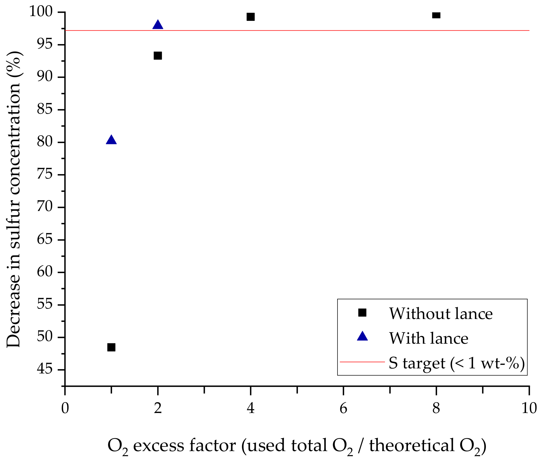
To reach the target S < 1 wt % in the slag after oxidation, sulfur content of the material needs to decrease 97.2% compared to the dried material. During the oxidation experiments O1–O4, 48.5%, 93.3%, 99.3%, and 99.7% decreases in sulfur content were observed, respectively. In the oxidations O1 and O2, performed with 65 mL/min oxygen flow rate and treating times of 30 and 60 min, respectively, the targeted sulfur level after the treatment was not reached. Using the amount of oxygen needed based on the theory, or double that amount, did not result in efficient sulfur removal. In both O3 and O4, the sulfur removal was more efficient, and the target was reached. Thus, four times the amount of theoretically needed oxygen was enough to remove sulfur to an adequate level.
During the experiments O5 and O6, conducted with the gas lance, the desulfurization was 80.2% and 97.9%, respectively, compared to that of the dried material. Therefore, the oxygen flow rate of 65 mL/min was not enough with a treating time of 30 min (O5), but with 60 min treatment (O6), the sulfur concentration decreased below the target value. Thereby, when the gas lance was used, the amount of theoretically needed oxygen was insufficient for efficient sulfur removal, but twice that amount resulted in an acceptable level of sulfur in the sample. Evidently, adding a gas lance to the experimental arrangement considerably enhanced the sulfur removal from the sample. This can also be seen in Figure 2, where the dependence between the reached decrease in the sulfur concentration and the O2 factor is depicted. The O2 factor describes how many times the theoretically needed amount of oxygen (Equation (1)) for efficient sulfur removal was used in an experiment.
Table 2 shows the results of the chemical analysis of the bulk compositions conducted with the ICP-OES method. The results show that most of the lead in the jarosite residue is volatilized into the off-gases already during the oxidation stage, and silver is fumed into the gas phase during the reduction stage. In the oxidation-reduction experiments conducted without the gas lance (O-R1 and O-R2), zinc and the remaining lead are quite effectively fumed during the reduction stage, but the target levels (Zn < 1 wt %, Pb < 0.03 wt %) in the bulk were not reached. During the experiments O-R3 and O-R4, conducted with the gas lance, due to the improved gas-liquid interaction, the removal of zinc and lead was more efficient and the target concentrations were reached. The increasing Mg content in the slag is mostly due to dissolution of the crucible material.
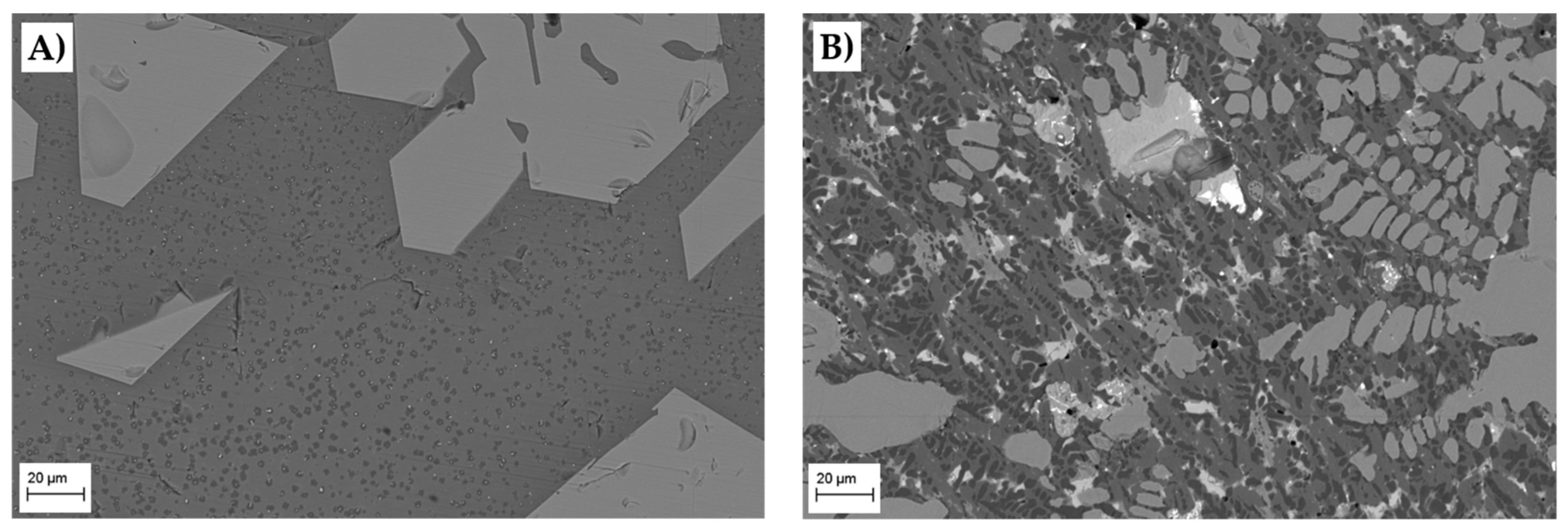
SEM-microstructure images in Figure 3 show the two main phases formed during the oxidation stage in oxidation experiments O4 and O6; liquid slag (darker matrix) and solid iron-magnesia-zinc spinels (medium grey areas). Figure 3B also shows some bright metal phase areas consisting mainly of lead with some copper, antimony, and silver.
Since the sample was slowly cooled to room temperature, there is a possibility that the spinels are formed during cooling. However, the angular shape of the spinels shown in Figure 3A suggests that the spinels are present at 1400 °C in solid form. When the treatment is conducted using the gas lance, the spinel structure has mostly lost its angular shape (Figure 3B). One possible explanation is the better mixing of sample material caused by the injection of gases directly onto the sample surface with the lance.
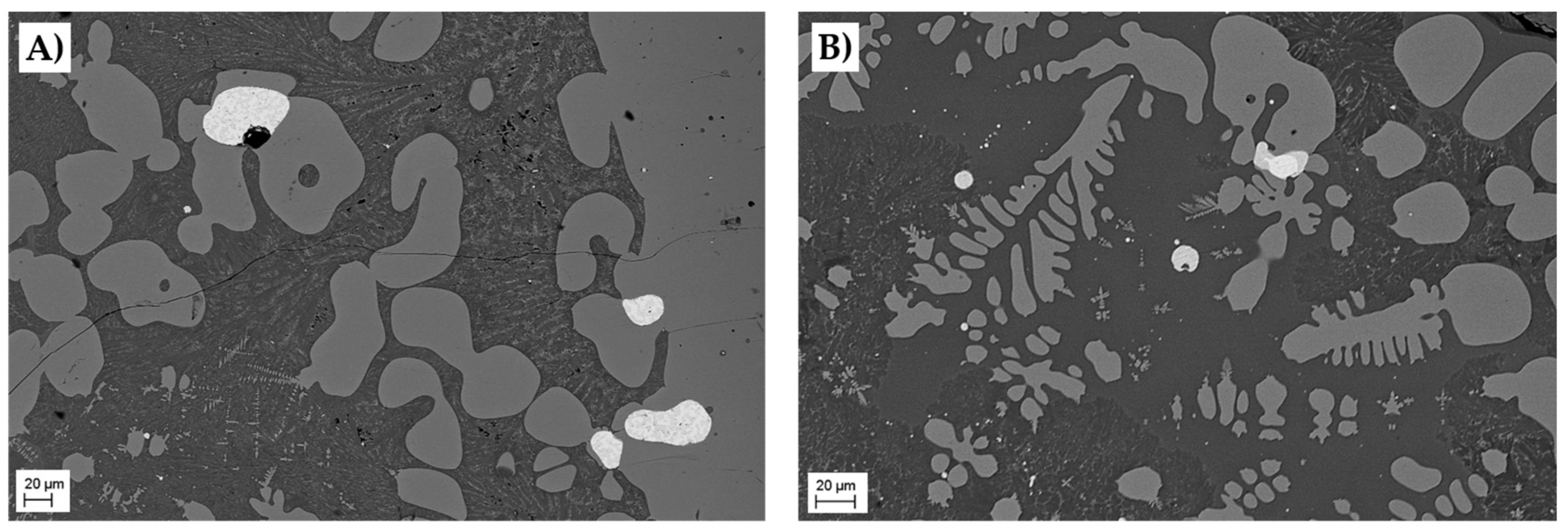
Figure 4A,B show the microstructure images of oxidation-reduction experiments O-R1 and O-R3, respectively. Three phases; liquid slag (dark grey matrix), spinels (medium grey areas), and metal or speiss droplets (light grey and white spots) are clearly distinguishable. The metallic droplets seem to be mostly attached to the spinels, which apparently has hindered the formation of larger metallic phase areas during the treatment. The same phenomenon has been reported and investigated, for example, in copper making conditions [22,23].
Figure 4B shows that the core and rim of the largest droplet consist of two different phases. Based on SEM-EDS analyses, the core of the droplet is mainly copper (>90 wt %), whereas the rim consists mainly of copper sulfide.
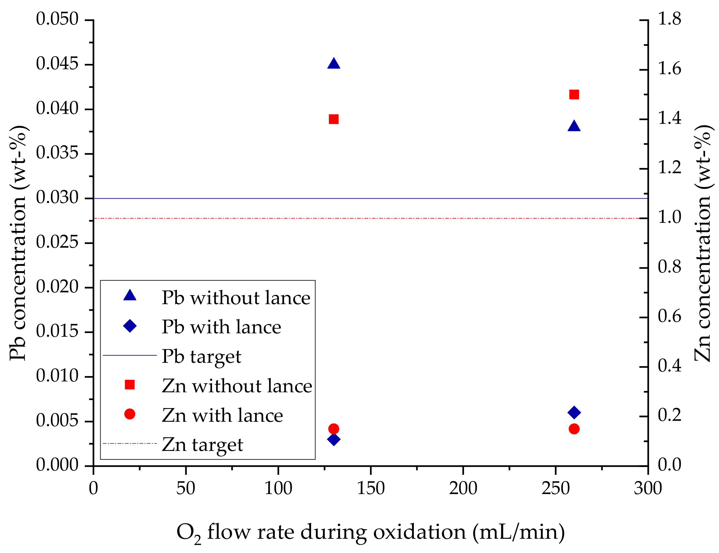
The bulk lead and zinc concentrations after oxidation-reduction experiments were plotted in Figure 5. Two experiments were conducted both with and without the gas lance, employing different oxygen flow rates (130 and 260 mL/min) during the oxidation stage. The parameters during the reduction stage were kept constant. The effect of oxygen flow rate is not very dramatic compared to the effect of the gas lance used.
The target lead and zinc concentrations after the pyrometallurgical oxidation-reduction treatment were <0.03 wt % and <1 wt %, respectively. As Table 2 and Figure 5 clearly show, these targets were not reached with conventional gas introduction into the furnace work tube. The results also indicate that the effect of oxygen flow rate is quite insignificant at this stage. By far the most significant improvements were reached with the installation of the gas injection lance, which improved the interaction between gas and liquid sample material, thus enabling the first steps of experimental parameter optimization regarding the gas flow rates.
4. Conclusions
Pyrometallurgical treatment as a processing option for jarosite leach residue from the hydrometallurgical zinc production was investigated with high-temperature laboratory-scale experiments. Guidelines for the study were obtained from a thermodynamic model [15] and earlier experiments conducted with small sample sizes [20]. The aim was to study how to conduct the pyrometallurgical treatment for obtaining a clean slag (Pb < 0.03, Zn < 1, S < 1 wt %) as a product and to recover the valuable metals from the residue.
Based on the results, it can be concluded that the installation of a top blowing gas injection lance drastically improves the contact between gas and molten sample material, thus accelerating the mass transfer of O2. Consequently, the assumption of the mass transfer of O2 being the rate-limiting step in the oxidation step of the process [20] was confirmed, as the lance enabled more efficient oxidation and allowed the use of lower gas flow rates. Significantly more efficient reduction was also achieved by the gas lance installation, as the removal of zinc and lead from the slag was drastically improved.
During this study, the target levels regarding lead, zinc, and sulfur concentrations in the final slag product were reached. However, the spinel phase appears to hinder the formation of larger metal or speiss phase areas, which would collect the valuable metals, as the small individual metal droplets attach preferentially to the spinels. This issue will be investigated in the future by changing the Fe-Si-Ca ratio of the starting material, and thus the composition of the spinels, or by adding more copper-containing material into the jarosite residue before the pyrometallurgical treatment. Changing the composition of the initial feed mixture may also have a reducing effect to the melting temperature, which would be a step further in optimizing the process conditions.
Author Contributions
M.R. designed as well as supervised the experiments, analyzed the data, and wrote most of the manuscript; S.N. performed the experiments and prepared the samples for analysis; L.K. conducted the SEM-EDS analyses, helped in analyzing the data, and wrote parts of the manuscript; A.J. supervised the study and helped writing the manuscript; J.S. initiated the work, provided the experimental targets, and revised the manuscript; P.T. helped in designing the experimental setup and provided insights regarding the study.
Funding
Financial support for this study is provided by Tekes nationally funded CMEco project.
Conflicts of Interest
The authors declare no conflicts of interest.
References
- Souza, A.D.D.; Pina, P.S.; Leão, V.A. Bioleaching and chemical leaching as an integrated process in the zinc industry. Miner. Eng. 2007, 33, 591–599. [Google Scholar] [CrossRef]
- Glinin, A.; Creedy, S.; Matusewicz, R.; Hughes, S.; Reuter, M. Outotec® ausmelt technology for treating zinc residues. In Proceedings of the EMC, Weimar, Germany, 23–26 June 2013; GDMB Verlag GmbH: Clausthal-Zellerfeld, Germany, 2013; pp. 485–494. [Google Scholar]
- Pappu, A.; Saxena, A.; Asolekar, S.R. Jarosite characteristics and its utilization potentials. Sci. Total Environ. 2006, 359, 232–243. [Google Scholar] [CrossRef] [PubMed]
- Ismael, M.R.C.; Carvalho, J.M.R. Iron recovery from sulphate leach liquors in zinc hydrometallurgy. Miner. Eng. 2003, 16, 31–39. [Google Scholar] [CrossRef]
- Han, H.; Sun, W.; Hu, Y.; Jia, B.; Tang, H. Anglesite and silver recovery from jarosite residues through roasting and sulfidization-flotation in zinc hydrometallurgy. J. Hazard. Mater. 2014, 278, 49–54. [Google Scholar] [CrossRef] [PubMed]
- Kerolli-Mustafa, M.; Ćurković, L.; Fajković, H.; Rončević, S. Ecological risk assessment of jarosite waste disposal. Croat. Chem. Acta 2015, 88, 189–196. [Google Scholar] [CrossRef]
- Mäkinen, J.; Salo, M.; Hassinen, H.; Kinnunen, P. Comparison of reductive and oxidative bioleaching of jarosite for valuable metals recovery. Solid State Phenom. 2017, 262, 24–27. [Google Scholar] [CrossRef]
- Kerolli-Mustafa, M.; Fajković, H.; Rončević, S.; Ćurković, L. Assessment of metal risks from different depths of jarosite tailing waste of Trepça Zinc Industry, Kosovo based on BCR procedure. J. Geochem. Explor. 2015, 145, 161–168. [Google Scholar] [CrossRef]
- Jha, M.K.; Kumar, V.; Singh, R.J. Review of hydrometallurgical recovery of zinc from industrial wastes. Resour. Conserv. Recycl. 2001, 33, 1–22. [Google Scholar] [CrossRef]
- Wegscheider, S.; Steinlechner, S.; Leuchtenmüller, M. Innovative concept for the recovery of silver and indium by a combined treatment of jarosite and electric arc furnace dust. JOM 2016, 69, 388–394. [Google Scholar] [CrossRef]
- Hughes, S.; Reuter, M.A.; Baxter, R.; Kaye, A. Ausmelt technology for lead and zinc processing. In Proceedings of the Lead & Zinc, Johannesburg, South Africa, 25–29 February 2008; pp. 141–162. [Google Scholar]
- Choi, C.Y.; Lee, Y.H. Treatment of zinc residues by Ausmelt technology at Onsan zinc refinery. In Proceedings of the REWAS ’99: Global Symposium on Recycling Waste Treatment and Clean Technology, San Sebastian, Spain, 5–9 September 1999; pp. 1613–1622. [Google Scholar]
- Wood, J.; Coveney, J.; Helin, G.; Xu, L.; Xincheng, S. The Outotec® Direct zinc smelting process. In Proceedings of the EMC 2015: European Metallurgical Conference, Düsseldorf, Germany, 14–17 June 2015; GDMB Verlag GmbH: Clausthal-Zellerfeld, Germany; pp. 537–548. [Google Scholar]
- Mombelli, D.; Mapelli, C.; Di Cecca, C.; Barella, S.; Gruttadauria, A.; Ragona, M.; Pisu, M.; Viola, A. Characterization of cast iron and slag produced by jarosite sludges reduction via Arc Transferred Plasma (ATP) reactor. J. Environ. Eng. 2018, 6, 773–783. [Google Scholar] [CrossRef]
- Toropainen, A. A Computational Thermodynamic Model for Conversion of Jarosite Residue into an Inert Slag via a Pyrometallurgical Process. Master’s Thesis, Aalto University, Espoo, Finland, 2016. [Google Scholar]
- Davies, R.H.; Dinsdale, A.T.; Gisby, J.A.; Robinson, J.A.J.; Martin, S.M. MTDATA-thermodynamic and phase equilibrium software from the national physical laboratory. Calphad 2002, 26, 229–271. [Google Scholar] [CrossRef]
- Gisby, J.; Taskinen, P.; Pihlasalo, J.; Li, Z.; Tyrer, M.; Pearce, J.; Avarmaa, K.; Björklund, P.; Davies, H.; Korpi, M.; et al. MTDATA and the prediction of phase equilibria in oxide systems: 30 years of industrial collaboration. Metall. Mater. Trans. B 2017, 48, 91–98. [Google Scholar] [CrossRef]
- Hoang, J.; Reuter, M.A.; Matusewicz, R.; Hughes, S.; Piret, N. Top submerged lance direct zinc smelting. Miner. Eng. 2009, 22, 742–751. [Google Scholar] [CrossRef]
- Chaidez-Felix, J.; Romero-Serrano, A.; Hernandez-Ramirez, A.; Perez-Labra, M.; Almaguer-Guzman, I.; Benavides-Perez, R.; Flores-Favela, M. Effect of copper, sulfur, arsenic and antimony on silver distribution in phases of lead blast furnace. Trans. Nonferrous Met. Soc. China 2014, 24, 1202–1209. [Google Scholar] [CrossRef]
- Rämä, M.; Jokilaakso, A.; Klemettinen, L.; Salminen, J.; Taskinen, P. Experimental investigation of pyrometallurgical treatment of zinc residue. In Proceedings of the Extraction 2018, Ottawa, ON, Canada, 26–29 August 2018; pp. 981–992. [Google Scholar]
- Lavrent’Ev, Y.G.; Korolyuk, V.N.; Usova, L.V. Second generation of correction methods in electron probe x-ray microanalysis: Approximation models for emission depth distribution functions. J. Anal. Chem. 2004, 59, 600–616. [Google Scholar] [CrossRef]
- Wilde, E.D.; Bellemans, I.; Zheng, L.; Campforts, M.; Guo, M.; Blanpain, B.; Moelans, N.; Verbeken, K. Origin and sedimentation of Cu-droplets sticking to spinel solids in pyrometallurgical slags. Mater. Sci. Technol. 2016, 32, 1911–1924. [Google Scholar] [CrossRef] [Green Version]
- Wilde, E.D.; Bellemans, I.; Campforts, M.; Guo, M.; Vanmeensel, K.; Blanpain, B.; Moelans, N.; Verbeken, K. Study of the effect of spinel composition on metallic copper losses in slags. J. Sustain. Metall. 2017, 3, 416–427. [Google Scholar] [CrossRef]
Figure 1.
Schematic of the experimental arrangement including the vertical tube furnace, gas train, sample, and gas cleaning system. R = rotameter, FC = mass flow controller, BTS = bromothymol blue.
Figure 1.
Schematic of the experimental arrangement including the vertical tube furnace, gas train, sample, and gas cleaning system. R = rotameter, FC = mass flow controller, BTS = bromothymol blue.

Figure 2.
The effect of O2 excess factor on the reached decrease in sulfur concentration of a sample. O2 excess factor describes how many times the theoretically needed amount of oxygen was used. The target for achieving S < 1 wt % is at 97.2%.
Figure 2.
The effect of O2 excess factor on the reached decrease in sulfur concentration of a sample. O2 excess factor describes how many times the theoretically needed amount of oxygen was used. The target for achieving S < 1 wt % is at 97.2%.

Figure 3.
Microstructures of oxidation experiments (A) O4 and (B) O6. The liquid slag phase is the darker matrix and the solid spinels are the lighter phase areas. The brightest area in (B) is a lead-rich metal phase.
Figure 3.
Microstructures of oxidation experiments (A) O4 and (B) O6. The liquid slag phase is the darker matrix and the solid spinels are the lighter phase areas. The brightest area in (B) is a lead-rich metal phase.

Figure 4.
Microstructures of oxidation-reduction experiments (A) O-R1 and (B) O-R3. The darker matrix is the liquid slag phase and the medium grey areas are the spinels. Light grey and white spots are metal or speiss droplets formed during the reduction stage.
Figure 4.
Microstructures of oxidation-reduction experiments (A) O-R1 and (B) O-R3. The darker matrix is the liquid slag phase and the medium grey areas are the spinels. Light grey and white spots are metal or speiss droplets formed during the reduction stage.

Figure 5.
Lead and zinc concentrations in the bulk samples after oxidation-reduction experiments, as a function of oxygen flow rate (130 or 260 mL/min) during the oxidation stage. The effect of the gas lance is quite dramatic.
Figure 5.
Lead and zinc concentrations in the bulk samples after oxidation-reduction experiments, as a function of oxygen flow rate (130 or 260 mL/min) during the oxidation stage. The effect of the gas lance is quite dramatic.


Table 1.
Experimental parameters used in the oxidation and oxidation-reduction experiments.
| Sample ID | Temperature (°C) | Oxidation Time (min) | Oxidizing Gas/Flow Rate (mL/min) | Reduction Time (min) | Reducing Gas/Flow Rate (mL/min) | |
|---|---|---|---|---|---|---|
| Oxidation | O1 | 1400 | 30 | O2/65 | - | - |
| O2 | 1400 | 60 | O2/65 | - | - | |
| O3 | 1400 | 60 | O2/130 | - | - | |
| O4 | 1400 | 60 | O2/260 | - | - | |
| O5 1 | 1400 | 30 | O2/65 1 | - | - | |
| O6 1 | 1400 | 60 | O2/65 1 | - | - | |
| Oxidation + Reduction | O-R1 | 1400 | 60 | O2/130 | 120 | CO-CO2 (50:50)/260 |
| O-R2 | 1400 | 60 | O2/260 | 120 | CO-CO2 (50:50)/260 | |
| O-R3 1 | 1400 | 60 | O2/130 1 | 120 | CO-CO2 (50:50)/260 1 | |
| O-R4 1 | 1400 | 60 | O2/260 1 | 120 | CO-CO2 (50:50)/260 1 |
1 Gas flow through a gas injection lance.
Table 2.
Bulk compositions of the samples based on the chemical analysis results (wt %, rounded to two decimals). Oxygen concentration of the samples was not determined, and the trace elements have been omitted.
Table 2.
Bulk compositions of the samples based on the chemical analysis results (wt %, rounded to two decimals). Oxygen concentration of the samples was not determined, and the trace elements have been omitted.
| Sample ID | Ag | Al | Ca | Cu | Fe | K | Mg | Na | Pb | Si | Zn | |
|---|---|---|---|---|---|---|---|---|---|---|---|---|
| Pre-treated | 0.02 | 0.95 | 4.20 | 0.28 | 26.40 | 0.45 | 0.23 | 2.20 | 5.30 | 3.60 | 5.90 | |
| Oxidation | O1 | 0.04 | 0.67 | 3.10 | 0.44 | 38.70 | 0.60 | 1.90 | 2.70 | 2.30 | 2.60 | 7.10 |
| O2 | 0.02 | 1.30 | 5.70 | 0.39 | 29.70 | 0.53 | 4.50 | 3.00 | 0.11 | 5.90 | 4.20 | |
| O3 | 0.02 | 1.30 | 5.90 | 0.39 | 28.80 | 0.49 | 4.60 | 2.90 | 0.81 | 5.50 | 4.80 | |
| O4 | 0.02 | 1.30 | 5.60 | 0.37 | 29.20 | 0.45 | 4.70 | 2.70 | 0.77 | 5.30 | 5.20 | |
| O5 1 | 0.03 | 1.20 | 5.40 | 0.39 | 31.30 | 0.51 | 4.10 | 2.90 | 0.25 | 5.50 | 5.40 | |
| O6 1 | 0.02 | 1.30 | 6.10 | 0.38 | 28.90 | 0.48 | 4.70 | 3.10 | 0.29 | 6.40 | 3.80 | |
| Oxidation + Reduction | O-R1 | 0.00 | 1.40 | 5.80 | 0.39 | 28.90 | 0.54 | 6.20 | 3.00 | 0.05 | 5.90 | 1.40 |
| O-R2 | 0.00 | 1.40 | 5.60 | 0.38 | 29.10 | 0.52 | 6.50 | 2.90 | 0.04 | 5.80 | 1.50 | |
| O-R3 1 | 0.00 | 1.40 | 5.90 | 0.35 | 28.00 | 0.28 | 6.80 | 2.40 | 0.00 | 6.50 | 0.15 | |
| O-R4 1 | 0.00 | 1.30 | 5.70 | 0.35 | 30.50 | 0.23 | 6.80 | 2.20 | 0.01 | 6.20 | 0.15 |
1 Gas flow through a gas injection lance.
© 2018 by the authors. Licensee MDPI, Basel, Switzerland. This article is an open access article distributed under the terms and conditions of the Creative Commons Attribution (CC BY) license (http://creativecommons.org/licenses/by/4.0/).
Share and Cite
MDPI and ACS Style
Rämä, M.; Nurmi, S.; Jokilaakso, A.; Klemettinen, L.; Taskinen, P.; Salminen, J. Thermal Processing of Jarosite Leach Residue for a Safe Disposable Slag and Valuable Metals Recovery. Metals 2018, 8, 744. https://doi.org/10.3390/met8100744
AMA Style
Rämä M, Nurmi S, Jokilaakso A, Klemettinen L, Taskinen P, Salminen J. Thermal Processing of Jarosite Leach Residue for a Safe Disposable Slag and Valuable Metals Recovery. Metals. 2018; 8(10):744. https://doi.org/10.3390/met8100744
Chicago/Turabian StyleRämä, Minna, Samu Nurmi, Ari Jokilaakso, Lassi Klemettinen, Pekka Taskinen, and Justin Salminen. 2018. "Thermal Processing of Jarosite Leach Residue for a Safe Disposable Slag and Valuable Metals Recovery" Metals 8, no. 10: 744. https://doi.org/10.3390/met8100744
Note that from the first issue of 2016, this journal uses article numbers instead of page numbers. See further details here.