
Brittle Fracture Behaviors of Large Die Holders Used in Hot Die Forging


School of Reliability and Systems Engineering, Beihang University, Beijing 100191, China
*
Author to whom correspondence should be addressed.
Metals 2017, 7(6), 198; https://doi.org/10.3390/met7060198
Submission received: 4 March 2017
/
Revised: 4 May 2017
/
Accepted: 25 May 2017
/
Published: 30 May 2017
(This article belongs to the Special Issue Mechanical Behavior of High-Strength Low-Alloy Steels)
Abstract
:Brittle fracture of large forging equipment usually leads to catastrophic consequences. To avoid this kind of accident, the brittle fracture behaviors of a large die holder were studied by simulating the practical application. The die holder is used on the large die forging press, and it is made of 55NiCrMoV7 hot-work tool steel. Detailed investigations including mechanical properties analysis, metallographic observation, fractography, transmission electron microscope (TEM) analysis and selected area electron diffraction (SAED) were conducted. The results reveal that the material generated a large quantity of large size polyhedral M23C6 (M: Fe and Cr mainly) and elongated M3C (M: Fe mainly) carbides along the martensitic lath boundaries when the die holder was recurrently tempered and water-cooled at 250 °C during the service. The large size carbides lead to the material embrittlement and impact toughness degradation, and further resulted in the brittle fracture of the die holder. Therefore, the operation specification must be emphasized to avoid the die holder being cooled by using water, which is aimed at accelerating the cooling.
1. Introduction
Forging is one of the major production processes in the mechanical industry. It is also an advanced manufacturing technique that provides important engine components. Forging technology is widely used to produce high-performance mechanical parts in both military and civil fields, such as engine blades that are manufactured by hot die forging. A major disadvantage of hot die forging is the poor process reliability, as well as the low durability of dies and die holders. In addition, the expense of hot forging equipment is quite high, which usually takes a proportion of 8–15% of all the productive task costs. If considering the failures of hot forging equipment and manufacturing loss during the production, the expense will increase to 30–50% [1,2]. Therefore, avoiding the failures of hot forging equipment is one of the most significant tasks for the forging industry.
The failures of dies and die holders are usually caused by wear, deformation, corrosion and fatigue during the production process [3,4]. Especially, the dies and die holders have to suffer long-term cyclic mechanical and thermal loads [5,6]. The cyclic mechanical loads can lead to fatigues, and the cyclic thermal loads can cause mechanical property degradation of dies and die holders. When the property degradation occurs, the die and die holder will easily fracture under the effect of the cyclic mechanical loads. The brittle fractures caused by property degradation usually lead to catastrophic consequences, and the preventive actions are difficult to find comparing with other failure modes [7,8,9,10]. The large die holder studied in this paper is made of 55NiCrMoV7 hot-work tool steel, which is similar to 5CrNiMo in chemical composition except with higher content of Cr and V. Compared with 5CrNiMo, the 55NiCrMoV7 has better hardenability and abrasion resistance. Furthermore, it has been widely used in aviation and motor industries [11]. Zhang et al. [12] studied the low cycle fatigue behaviors of 55NiCrMoV7 under different working temperatures. The results show that the cyclic load and working temperature can cause the cyclic softening and microstructure variation, which can lead to the property degradation of 55NiCrMoV7. Therefore, it is important to learn the brittle fracture mechanism of the large die holder and to exclude the factors resulting in material embrittlement. Moreover, it is necessary to take preventive actions to avoid brittle fracture, reduce economic losses and personnel casualties.
In this paper, the brittle fracture behaviors of the large press die holder was studied. Firstly, the failure background and the failure mode of the die holder are described. Then, the analysis techniques and methods, such as chemical composition analysis, metallographic observation, mechanical properties testing, tempering and water-cooling treatment, microstructure analysis and selected area electron diffraction (SAED), are scheduled. Thirdly, the experiments are conducted, and the results are comprehensively discussed. Finally, some conclusions and suggestions are made.
2. Failure Background of the Die Holder
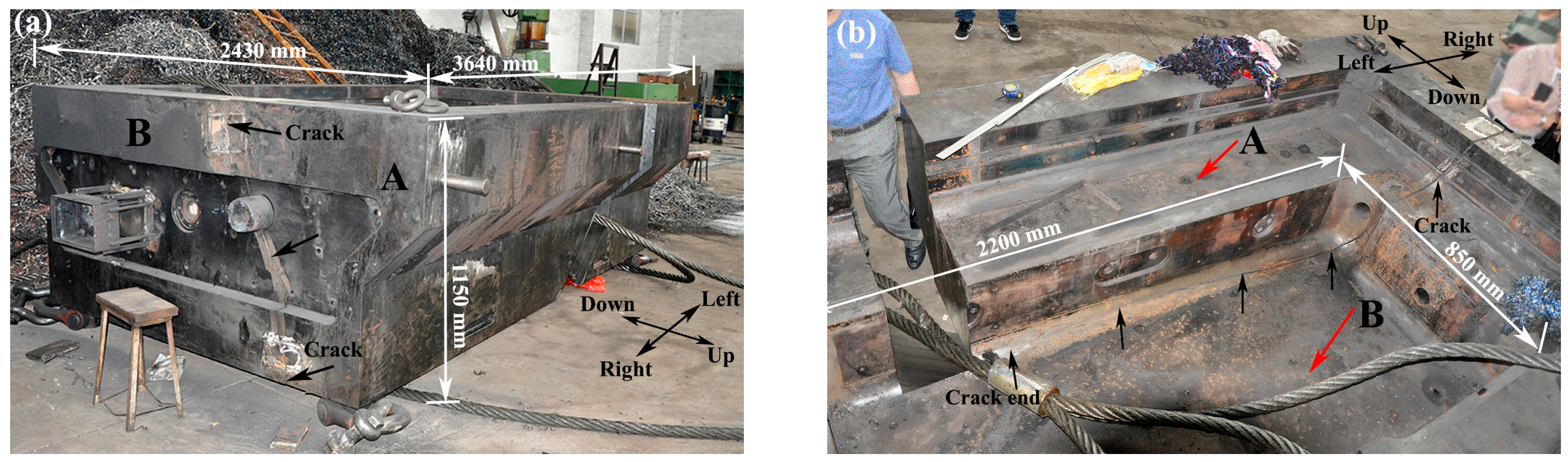
The die holder studied in this paper is used on a large screw press for hot die forging. The profile of the die holder is shown in Figure 1. The outline size of the die holder is 3640 mm (length) × 2430 mm (width) × 1150 mm (height) and the inner cavity size is 2200 mm (length) × 850 mm (width). The weight of the die holder is 62.26 t. The production processes of the die holder include vacuum smelting, forging, heat treatment and machining. According to the technical requirement, the material of the die holder is set to be 55NiCrMoV7 hot-work tool steel. The initial heat treatment of the die holder is as follows. Firstly, the die holder was roughly forged. Then, it was handled by using high temperature diffusion annealing. After that, the die holder was heated up from 20 °C to 850 °C at the speed of 50 °C/h. Then, it was austenitized for 15 h at 850 °C. Thirdly, the die holder was processed by using step quenching (water-oil quenching) one time, which is first water-quenched for 30 min and then oil-quenched to room temperature. Finally, it was submitted to a double tempering treatment, first at 620 °C and then at 560 °C. After the heat treatment, the microstructure is tempered martensite.
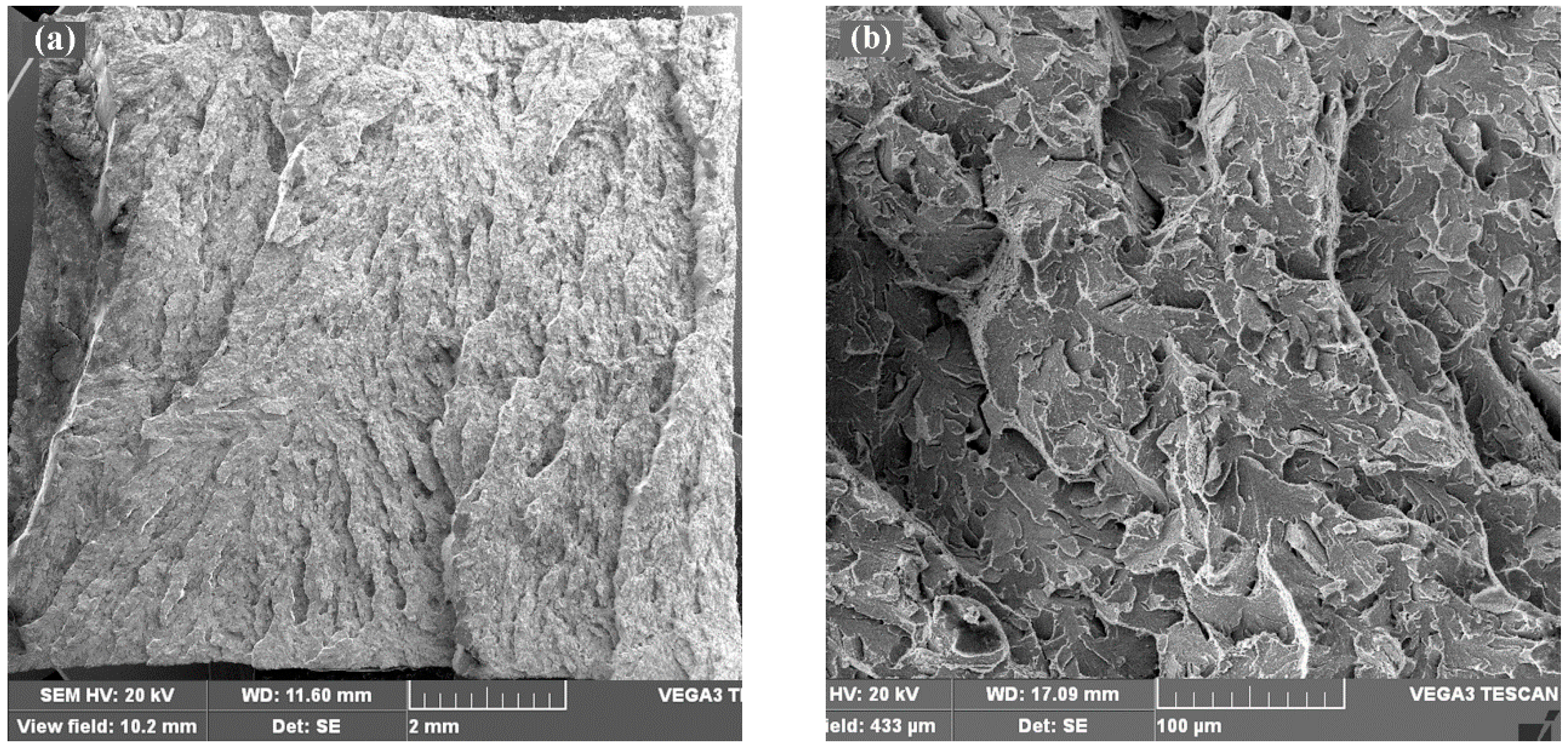
The die holder generated a large crack during the process of forging aero-engine blades. The crack penetrates the bottom and the right side of the die holder whose length extends as long as 2316.7 mm as shown in Figure 1 and Figure 2, where the crack orientation is marked by using the arrows. Figure 2a is the crack morphology, where A represents the up side of the crack and B represents the down side, as the coordinates show in figures. Figure 2b is the numbered fracture of the A side that was cut from the die holder along the crack. On the inner bottom of the die holder, which is the top edge of the fracture, there is an obvious semicircular fatigue area (region 1). Furthermore, along the inner bottom surface, there are three surface cracking zones where the crack propagation directions are different from that of the fatigue area. The fracture characteristics of the die holder have been studied in our previous investigation [13], and the information about the fracture characteristics are only briefly described in this section. The failure analysis of the die holder [13] has revealed that the crack initiated from the semicircular fatigue area (region 1) and the surface cracking zones (the top edges of region 2, region 4 and region 9, which are on the surface of the inner bottom as shown in Figure 2), where the fatigue is point source and the surface cracking zones are linear sources. The crack propagation region (the whole fracture except for region 1 and region 5) is rapid brittle fracture with large radial ridges. The microscopic morphology is quasi-cleavage, which is characterized by river patterns and tear ridges as shown in Figure 3.
The semicircular fatigue region and surface cracking zones of the die holder are shown in Figure 4. The semicircular fatigue region is about 40 mm in diameter, and the region accounts for 0.02% of the whole fracture. The thickness of the surface cracking zones are 5–10 mm, as the red arrows show in Figure 4, which take up 0.04% of the whole fracture. The die holder had been working for two years before failure. During the working process, the die holder had forged 113,025 products made of high strength stainless steel, titanium alloy and high temperature alloy at 150 °C to 350 °C, and it had endured the impact loads 351,089 times. The impact loads are usually between 180 MN and 280 MN. The maximum and minimum loads are 350 MN and 83 MN, respectively. The bearing capacity of the die holder is 350 MN, so the service stress of the die holder does not exceed the ultimate strength of the material. Considering that the fracture sources only account for 0.06% of the total fracture, the service stress is not large enough to explain such a large and rapid brittle fracture. Therefore, it must be other reasons that led to the brittle fracture. Thus, further study was made in this paper.
3. Methods
In order to determine the reasons why brittle fracture of the die holder happens, extensive samples are cut from the broken die holder, and the research scheme of the paper is designed as follows. In this paper, region 4 contains three parts of the bottom, which is the main brittle fracture region and suffered the most severe environment stress. The regions 4-1, 4-2 and 4-3 refer to the upper, middle and lower regions of the die holder bottom, respectively. Samples cut from region 4, which can represent the mechanical properties of the whole bottom, were tested by using the chemical composition and metallographic analysis, hardness testing, tensile experiment and impact property testing. Meanwhile, the impact fracture features were investigated. Additionally, there is no original material of the die holder, so region 6, which suffered the least temperature and mechanical load effects, are used for comparison with region 4. Furthermore, the tempering and water-cooling experiment was designed to simulate the practical environment stress of the die holder, and the effect of cyclic tempering and water cooling on the material impact property was studied as well [14]. That is, the samples of region 6 were tempered for 40 min at the temperature of 150 °C, 250 °C, 350 °C and 450 °C, respectively, and then water-cooled. After tempering and water-cooling treatment, the impact property of region 6 was tested and the impact fractures were observed by using a scanning electron microscope (SEM) (TESCAN CHINA, LTD., Shanghai, China). Finally, the transmission electron microscope (TEM) (JEOL (BEIJING) CO., LTD., Beijing, China) and selected area electron diffraction (SAED) were applied to analyze the microstructure and precipitates of the regions 4 and 6 in detail to investigate the reasons for brittle fracture.
4. Results
4.1. The Chemical Composition and Metallography
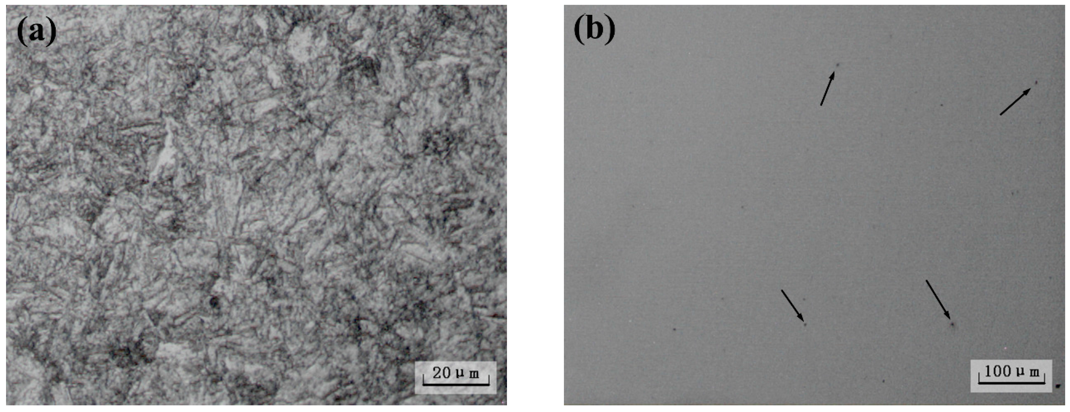
The chemical composition analysis shows that the chemical composition meets the technical requirement of the die holder as shown in Table 1. The metallographic samples removed from the broken die holder were eroded by using the 1% HNO3 + C2H5OH solution. The grain size was measured by using the comparison method, which is to compare the grain size under 100× magnification with the standard grain size chart. The results show that the die holder has a fine grain size of level 7 to 8. The microstructure is homogeneous with tempered martensite and there is no oxidation and decarbonization as shown in Figure 5a. In addition, the material has dot shaped nonmetallic inclusions. There is no large inclusion and obvious nonmetallic inclusion segregation zone as shown in Figure 5b. In conclusion, the material fits the technical requirements and there are no metallurgical defects.
4.2. Hardness Analysis
The Rockwell hardness of samples cut from region 4 and region 6 were measured as shown in Table 2. The results show that the hardness of region 4 is distributed between HRC 32.9 and HRC 33.1, which is lower than the technical requirement (HRC 36–HRC 40). As a whole, the hardness of region 4 is relatively homogeneous. However, the hardness of region 6 is HRC 37.2, which conforms to the technical requirements. Compared with region 6, the hardness of region 4 decreased by 11.3%, which indicates that the property of region 4 has degraded. According to Zhang’s study, the service temperature of 55NiCrMoV7 can cause the tempering effect (aging effect), which results in the hardness decreasing, even though the service temperature is lower than the initial tempering temperature. Furthermore, the cyclic loads also can lead to the hardness diminution. As the hardness of region 6 has no obvious degradation, it can be concluded that region 6 had less cyclic mechanical and thermal loads than region 4, which is consistent with the practical service situation of the die holder. The hardness of region 6 is the most similar with the original material, so the samples of region 6 are used to compare with region 4 in the following.
4.3. Tensile Properties
The tensile properties of region 4 and region 6 were tested. The results are shown in Table 3. It turns out that the tensile properties of region 4 increase in turn from the upper region to the lower region. Moreover, the tensile properties of the upper region and the middle region are almost the same, while the lower region is higher than those of the other two regions. The tensile strengths of region 4 are between 1017 MPa and 1033 MPa. It meets the technical requirement, which is 1000–1250 MPa. The yield strength of region 4 is between 819 MPa and 833 MPa, which is in accordance with the technical requirements (≥650 MPa). The elongation (A) of the lower region is 16.5%, which meets the technical requirements. However, the elongations of the upper region and the middle region are lower than 15%. As a whole, the tensile properties of the lower region are better than those of the upper and middle region. Additionally, the tensile properties of region 6, which fit the technical requirement well, are superior to those of region 4, which indicates that the properties of region 6 are the most similar with the original material. It has to clarify that the tensile properties of region 4 and region 6 just meet the minimum value of the technical requirement, which indicates that the properties of both regions have degraded. Furthermore the degradation degree of region 6 is lower than region 4. Similarly, the different properties of region 4-1, 4-2 and 4-3 are also related to the degradation degree, which will be discussed in Section 5.
4.4. Impact Property and Fracture Morphology
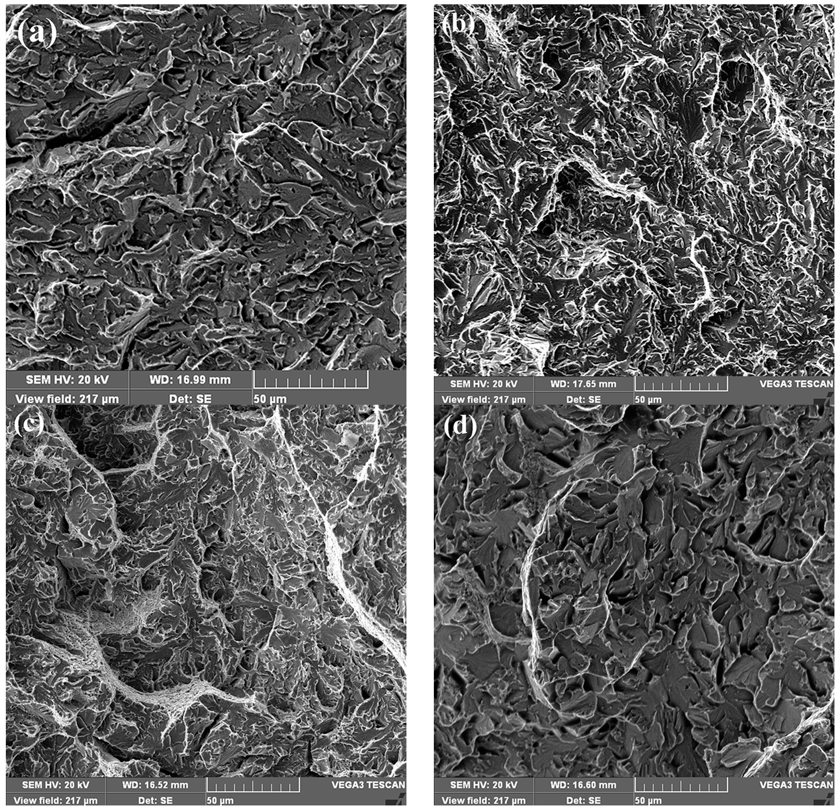
Impact toughness is one of the most important parameters to evaluate the brittle fracture resistance of material. Therefore, the impact property of v-notched samples removed from region 4 and region 6 were measured. The results are shown in Table 4. The impact toughness of region 4 is between 9.0 J/cm2 and 9.8 J/cm2, which are much lower than the technical requirements (≥25 J/cm2). Moreover, the impact toughness of region 4-1, 4-2 and 4-3 decreases slowly in turn. However, the impact toughness of region 6 is 40.0 J/cm2, which fits the technical requirements well. Compared with region 6, the impact toughness of region 4 declines by 76.5%, which reveals that the impact toughness of region 4 has seriously degraded. The low impact toughness of region 4 also indicates that region 4 has pretty low impact resistance, which is easy to fracture under impact loads.
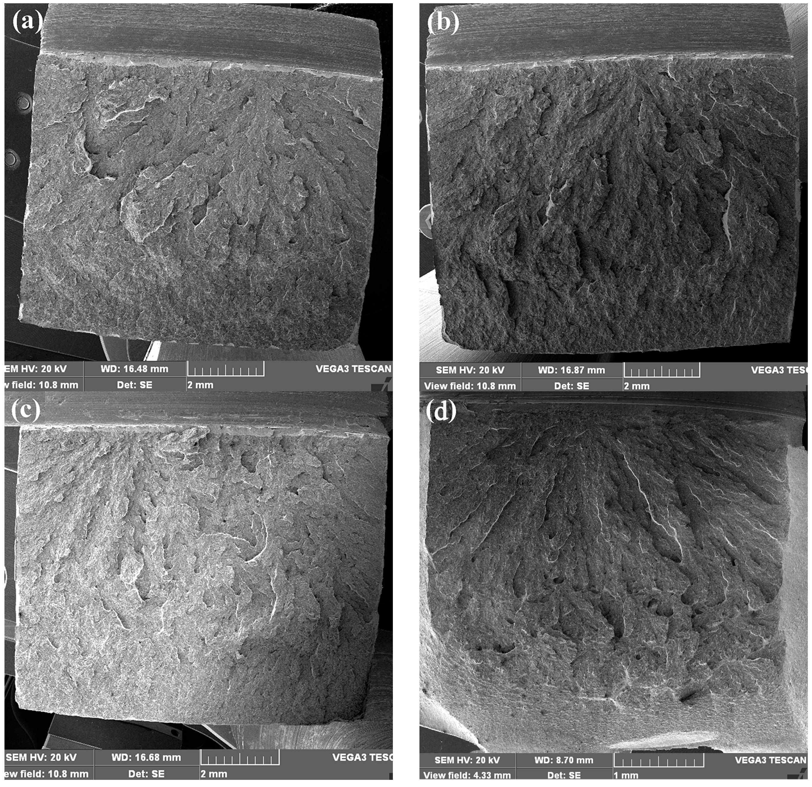
To compare the impact fracture morphology of region 4 with region 6 as well as the brittle fracture, SEM observation was carried out. The impact fractures of region 4 and region 6 are shown in Figure 6. It can be seen that there is little fiber region and shear lip on the fracture surfaces of region 4, and most of the fracture surface is the radial region with a large quantity of radial ridges, which indicates that the impact toughness of region 4 is very low. However, the impact fracture of region 6 has obvious shear lip, which is much larger than that of region 4. It indicates that the impact toughness of region 6 is much higher than that of region 4, which is consistent with the tested impact toughness.
To further study the property differences of region 4 and region 6, the high magnification morphology of radial regions are shown in Figure 7. It is obvious that the microscopic morphology of the radial region on region 4 is classical quasi-cleavage with large cleavage step patterns and tear ridges. The microscopic morphology of region 6 is also quasi-cleavage, but the surface is more flat than that of region 4, and there are no obvious cleavage step patterns, which also indicates that the impact toughness of region 4 is much lower than that of region 6.
4.5. The Tempering and Water-Cooling Effect on Impact Property
The above analysis has demonstrated that the mechanical properties of region 6 are much superior to those of region 4. Furthermore, all the mechanical properties of region 6 meet the technical requirements, while those of region 4 do not meet them. It reveals that the properties of region 4 have degraded, especially the impact toughness which represents the impact resistance of the material. Furthermore, the mechanical properties of region 6 are the most similar to the original material of the die holder. Therefore, samples cut from region 6 are employed for tempering and water-cooling experiments.
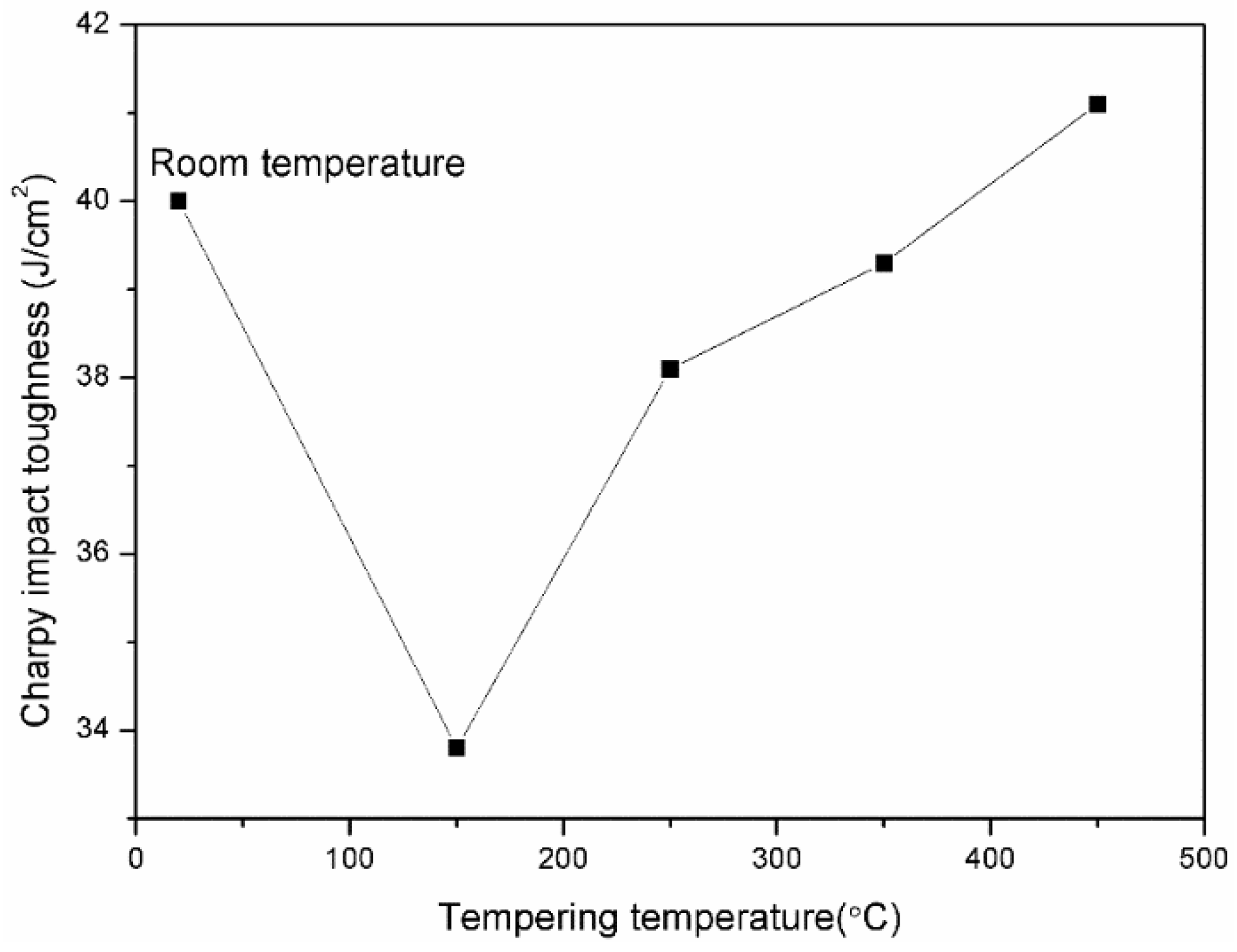
To investigate the reason for impact toughness degradation, the tempering and water-cooling experiment was used on the samples of region 6 to simulate the practical environment stress of the die holder. Each experiment has three parallel samples, and the results given are the average values. The results are shown in Figure 8. The impact toughness of region 6 is 40 J/cm2 before tempering and water-cooling treatment, which is much higher than the minimum value of technical requirements (25 J/cm2). The results demonstrate that region 6 is of excellent impact resistance. However, the impact toughness decreases to 33.8 J/cm2 after tempering and water-cooling treatment at 150 °C. The impact toughness increases with the tempering temperature rising. When the sample is tempered and water-cooled at 450 °C, the impact toughness reaches 41.1 J/cm2, which is slightly above the impact toughness before tempering and water-cooling treatment. In a word, the impact toughness degradation is caused by tempering and water-cooling treatment at the temperatures between 150 °C and 350 °C. During the service process of the die holder, the temperature which region 4 endured is right between 150 °C and 350 °C. It means that the impact toughness degradation of region 4 is related to the tempering and water-cooling effects. It should be noticed that the minimum impact toughness after tempering and water-cooling treatment is 33.8 J/cm2, but the impact toughness of region 4 is much lower than 33.8 J/cm2. The reason is that the impact toughness is measured after tempering and water-cooling treatment once. However, the die holder has endured the tempering and water-cooling effects at 150 °C to 350 °C for 113,025 times as well as the cyclic loads for 351,089 times, which would result in much lower impact toughness as measured in region 4.
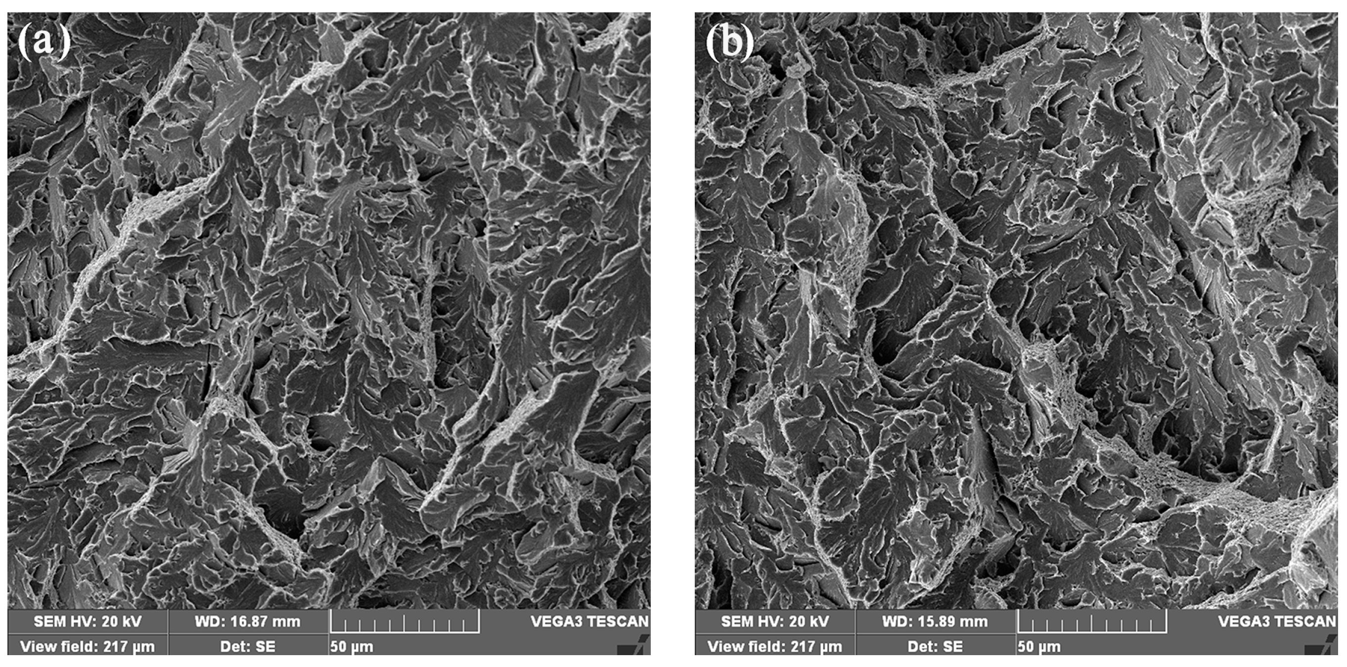
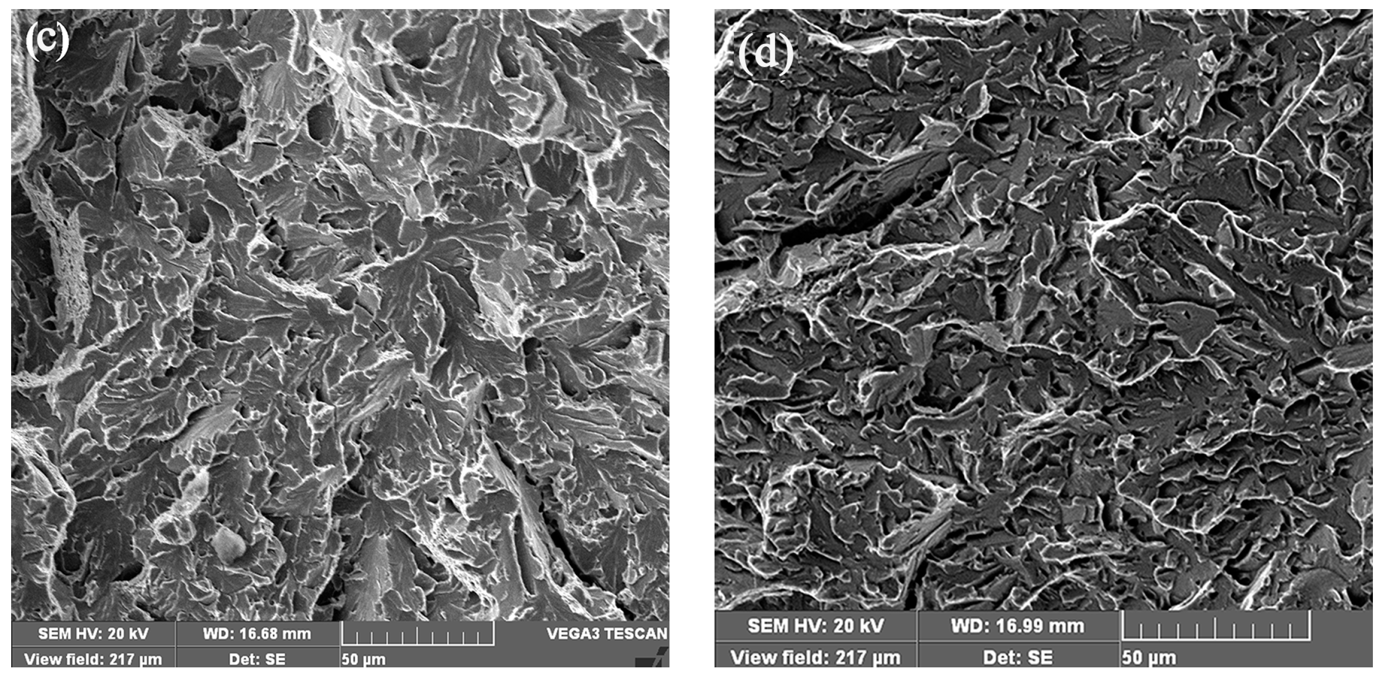
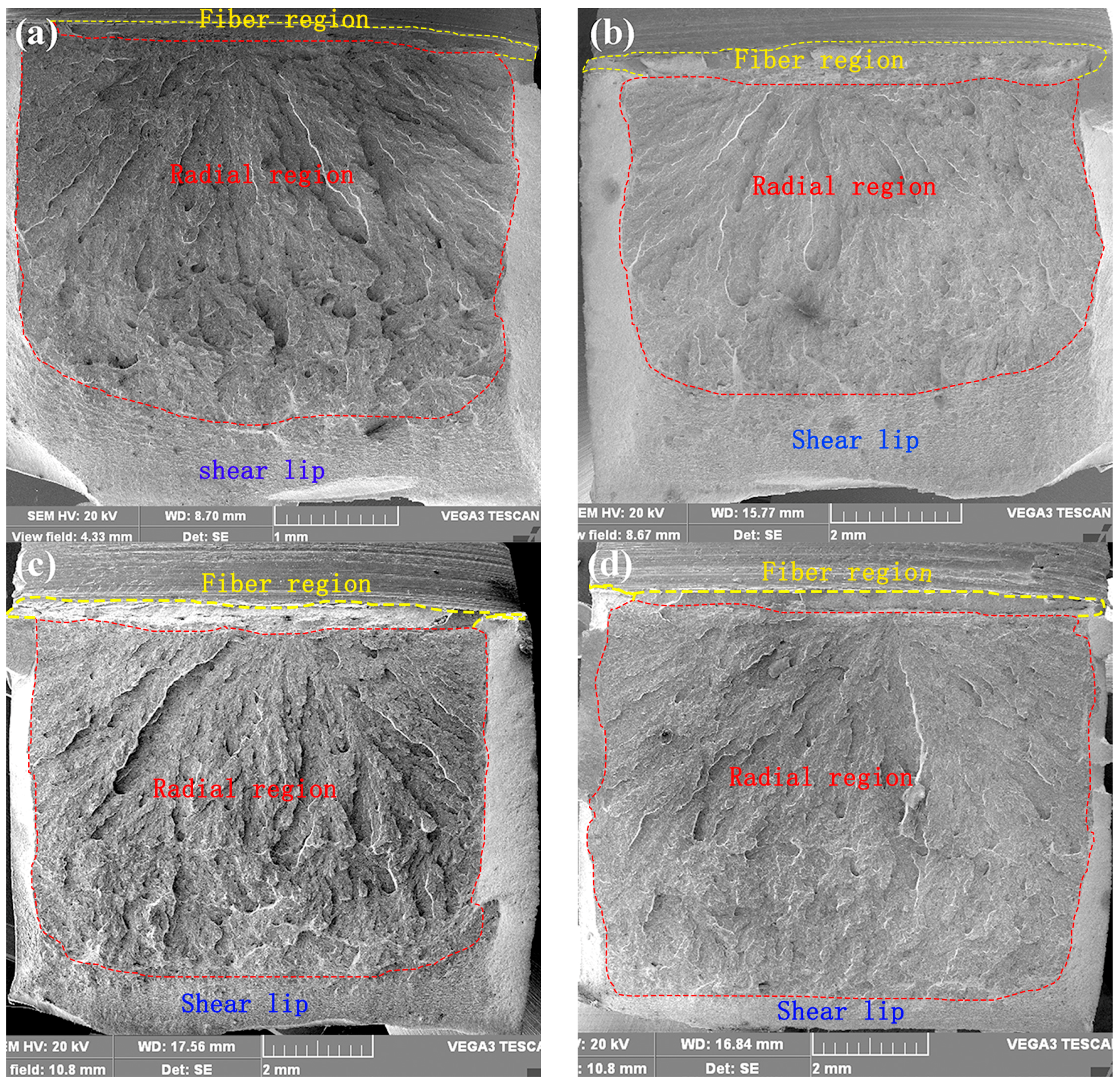
The impact fractures of region 6 after tempering and water-cooling treatment at different temperatures are shown in Figure 9. It can be seen that the fracture morphology with low magnification is similar, which includes three regions. The upper part of the fracture is the fiber region. The middle is the radial region. The lower, left and right sides of the fracture are shear lip. Moreover, the size of different regions on each fracture changes with the tempering temperature. The proportion of radial region and shear lip on two sides increase with the temperature rising, but the lower shear lip decreases. The radial region after being tempered was at 250 °C, which is the same as the fracture of region 4, as shown in Figure 3a.
The brittle fracture morphology of the die holder is the same as the radial region of the impact fracture at low magnification. Therefore, the radial region morphology of region 6 was observed by using SEM at high magnification as shown in Figure 10. Though the samples were tempered and water-cooled at different temperatures, the microscopic morphology of radial regions are all quasi-cleavage. However, the quasi-cleavage patterns and quasi-cleavage steps are various at different tempering temperatures. The microscopic fracture of region 4 has the same quasi-cleavage morphology as that tempered at 250 °C, both of which have obvious quasi-cleavage steps as shown in Figure 3b and Figure 10c.
4.6. Transmission Electron Microscope Analysis
To investigate the mechanism of impact toughness degradation of region 4, the microstructures of region 4 and region 6 before tempering and water-cooling treatment were compared by using the TEM. Figure 11 is the bright-field images of region 4 and region 6. The microstructure of the two regions are both lath martensite and carbides [11].
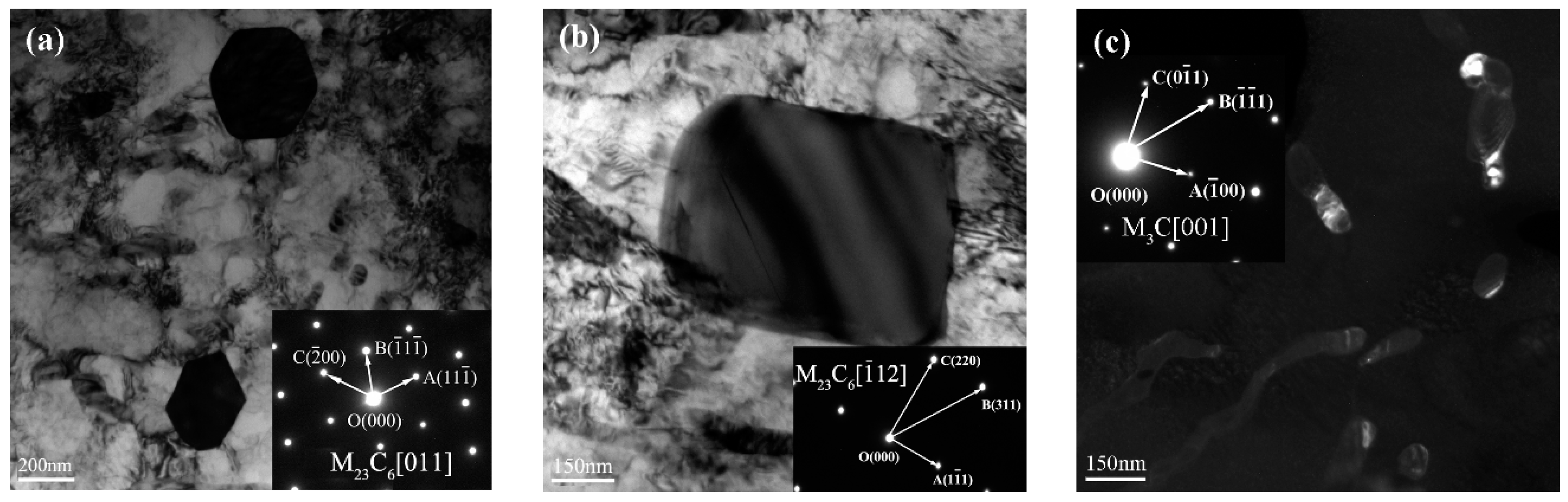
The observation of precipitate morphology results indicate that there are many precipitates with different shapes in region 4 and region 6. There are three kinds of precipitates in region 4: the hexagonal precipitates whose sizes are 200 nm to 300 nm as shown in Figure 12a. The tetragonal precipitates whose sizes are 400 nm to 640 nm as shown in Figure 12b. The elongated precipitates, most of which are between 50 nm and 1.5 μm, and a few of them are less than 50 nm as shown in Figure 12c.
In order to determine the phase of the precipitates, the SAED was utilized on precipitates. The results reveal that the SAED patterns of hexagonal precipitates and tetragonal precipitates belong to the different crystal zone axes of the same face-centered lattice as shown in Figure 12. Furthermore, they have identical chemical composition. Therefore, the hexagonal precipitates and the tetragonal precipitates are the same substance, which are collectively called the polyhedron precipitates. Compared with the standard SAED patterns data of precipitates in steel, the SAED pattern of elongated precipitates is the same as the pattern of the [001] crystal zone axis of orthorhombic lattice.
The precipitates were affirmed by comparing the lattice parameter of indexed patterns with the standard PDF cards, as well as by analyzing the chemical composition of precipitates (Table 5). The polyhedron precipitates are M23C6 carbides, where M are mainly Fe and Cr. The elongated precipitates are M3C carbides, where M are mostly Fe. In region 4, the small size M3C carbides are distributed mainly in lath martensite, while the large size M3C carbides are distributed mainly along the boundaries of lath martensite as shown in Figure 12a.
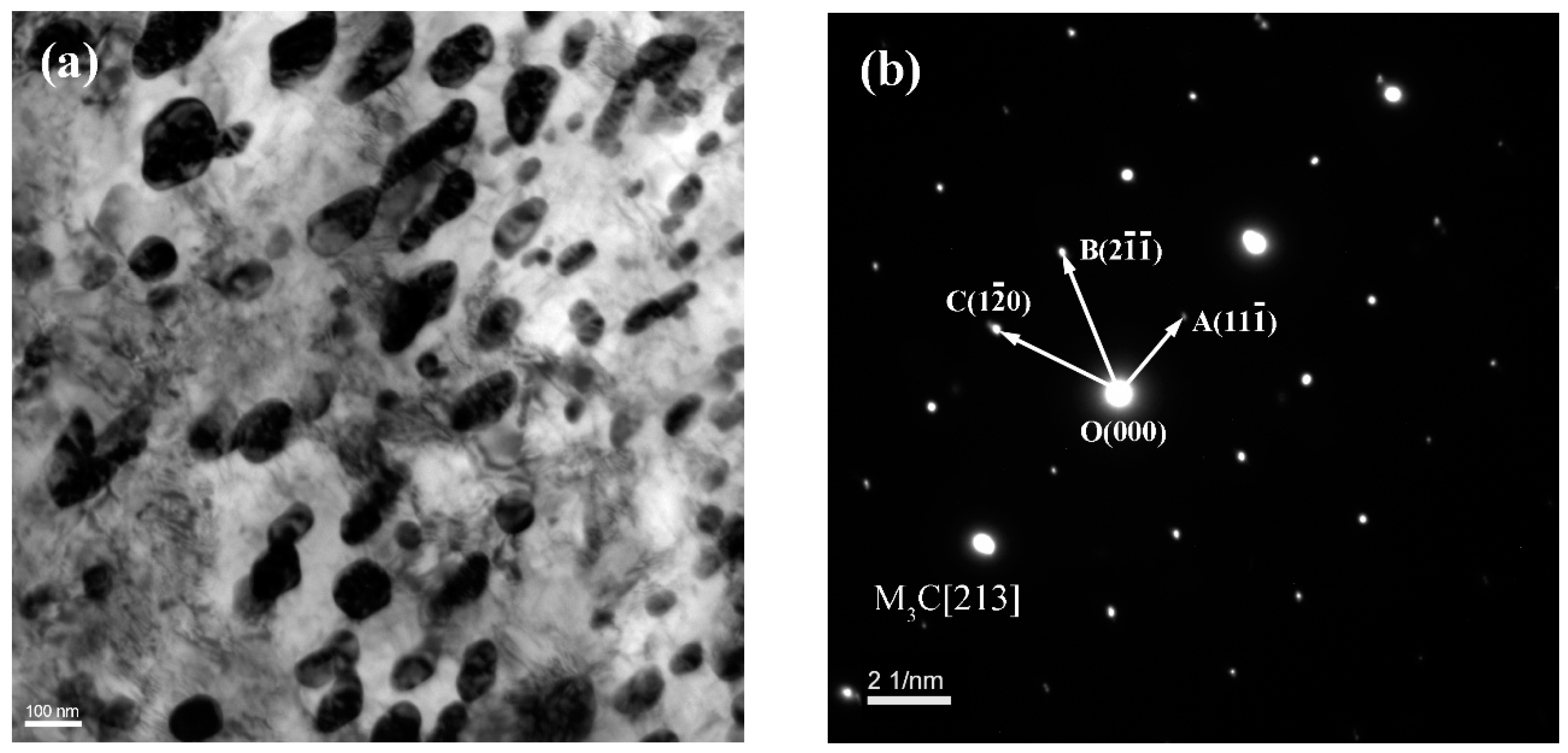
As shown in Figure 13, the precipitates of region 6 are mainly elongated precipitates whose sizes are mainly within 100 nm. Most of the precipitates are almost globular, except for a few that are elongated. Therefore, the precipitates’ size in region 6 is much smaller than those of region 4. In addition, region 6 has no polyhedron precipitates. The SAED patterns of elongated precipitates were indexed, and the results are the same as that of region 4, which is shown in Figure 13. The elongated precipitates are M3C carbides, where M are mainly Fe [15,16]. However, the M3C carbides of region 6 are distributed mainly in lath martensite, and only a few of them are located at the martensitic lath boundaries.
The M23C6 and M3C carbides are both hard and brittle phases in tempered steel. M23C6 carbides are mainly formed in the process of heat treatment, which are transformed by undissolved MC carbides during the tempering process. However, the carbides in tempered 55NiCrMoV7 are not always changeless. The existing small carbides can coalesce and grow up under the interaction of cyclic mechanical and thermal loads during the service process [12]. Especially, the fatigue loads can accelerate the growth of M23C6 carbides [17,18,19]. In region 4, plenty of large size M23C6 carbides that are formed along the martensitic lath boundaries can decrease the impact toughness. Moreover, the large size M3C carbides can seriously decrease the impact toughness and increase the material brittleness, especially the elongated M3C carbides that are distributed in the boundaries of lath martensite. Finally, the interaction of M23C6 and M3C carbides result in the impact toughness degradation [20,21].
5. Discussion
During the service process, the die holder needs to be preheated to 240 °C by using heating rods built in the bottom of the die holder before working. The die holder is used to install the forging die. Furthermore, the inner bottom (region 4) of the die holder would directly contact with the die where the temperature is about 250 °C. Therefore, the inner bottom temperature of the die holder remains at 250 °C during the forging process, while the temperature of the undersurface and region 6 may slowly decrease because they are exposed in air. According to the operation rule, each forging product uses one exclusive forging die, and the die and die holder must be air-cooled when replacing forging product. However, in order to accelerate cooling, operators usually cool the die holder by using water, which results in the cyclic tempering and a water-cooling effect on the bottom of the die holder. The die holder has endured the tempering and water-cooling effect at 150 °C to 350 °C 113,025 times as well as the cyclic mechanical loads 351,089 times. In this paper, the tempering and water-cooling experiment successfully simulates the effect. In addition, the results demonstrate that the long-term combined action of tempering and water-cooling effect at 150–350 °C, as well as the cyclic mechanical loads, caused the growth and coalescence of carbides in the microstructure of 55NiCrMoV7 steel. Then, the large size M23C6 and M3C carbides distributed at the boundaries of lath martensite lead to the degradation of impact toughness and the material embrittlement, which can easily result in brittle fracture. Additionally, the forging forces act mainly on the inner bottom of the die holder, so region 4 suffers more severe cyclic mechanical loads, as well as tempering and a water-cooling effect, than other regions. However, region 6 only suffers the cyclic tempering without water-cooling, as it is far away from the water-cooling region. Therefore, it was the long-term cyclic water-cooling as well as the cyclic mechanical loads during the service process that result in the serious impact toughness degradation in region 4. The temperature of the inner bottom is higher than the undersurface, and the water cooling also occurs on the inner bottom, so the tempering and water-cooling effect on the inner bottom is more obvious than that of the undersurface. Therefore, the mechanical properties of region 4-1, 4-2 and 4-3 are different. Because region 6 is far away from the regions of the tempering and water-cooling treatment as well as the cyclic mechanical loads, the large carbides of region 6 have not been formed, and, therefore, it does not present the brittleness. Finally, because the impact resistance of region 4 has seriously degraded, the brittle fracture whose microscopic feature is quasi-cleavage occurred on the whole bottom of the die holder under impact load during forging.
6. Conclusions
- The serious material embrittlement and brittle fracture of the die holder are caused by the long-term tempering and water-cooling effect as well as the cyclic mechanical loads. In addition, the operation specification must be emphasized to avoid the die holder being cooled by using water during the working process.
- The tempering and water-cooling treatment at 150 °C to 350 °C could lead to the impact toughness degradation and material embrittlement. The effect of material embrittlement declines with the tempering temperature rising.
- The material embrittlement are related to the large size M23C6 (M: mainly Fe and Cr) and M3C carbides (M: mainly Fe) distributed in the martensitic lath boundaries.
Acknowledgments
The research was supported by the National Technology Foundation of China (No. JSZL2014601B004). The authors are grateful to Yaozhong Zhang and Hongxiang Jing from the Wuxi Turbine Blade Co., Ltd., Wuxi, China for the technology and equipment support. The guidance and help of Fanchang Zeng from the Confederation of Chinese Metalforming Industry and Peidao Zhong from Beijing Institute Aeronautical Materials are greatly acknowledged.
Author Contributions
Hongxun Wang and Weifang Zhang conceived and designed the experiments; Jingyu Zhang and Yuanxing Huang performed the experiments; Hongxun Wang and Weifang Zhang analyzed the data; Wei Dai contributed reagents/materials/analysis tools; Hongxun Wang and Wei Dai wrote the paper.
Conflicts of Interest
The authors declare no conflict of interest.
References
- Gronostajski, Z.; Kaszuba, M.; Hawryluk, M.; Zwierzchowski, M. A review of the degradation mechanisms of the hot forging tools. Arch. Civ. Mech. Eng. 2014, 14, 528–539. [Google Scholar] [CrossRef]
- Kchaou, M.; Elleuch, R.; Desplanques, Y.; Boidin, X.; Degallaix, G. Failure mechanisms of H13 die on relation to the forging process—A case study of brass gas valves. Eng. Fail. Anal. 2010, 17, 403–415. [Google Scholar] [CrossRef]
- Gronostajski, Z.; Kaszuba, M.; Polak, S.; Zwierzchowski, M.; Niechajowicz, A.; Hawryluk, M. The failure mechanisms of hot forging dies. Mater. Sci. Eng. A 2016, 657, 147–160. [Google Scholar] [CrossRef]
- Okazaki, Y. Comparison of fatigue properties and fatigue crack growth rates of various implantable metals. Materials 2012, 5, 2981–3005. [Google Scholar] [CrossRef]
- Kim, T.H.; Kim, B.M.; Choi, J.C. Prediction of die wear in the wire-drawing process. J. Mater. Process. Technol. 1997, 65, 11–17. [Google Scholar] [CrossRef]
- Alimi, A.; Fajoui, J.; Kchaou, M.; Branchu, S.; Elleuch, R.; Jacquemin, F. Multi-scale hot working tool damage (X40CrMoV5-1) analysis in relation to the forging process. Eng. Fail. Anal. 2016, 62, 142–155. [Google Scholar] [CrossRef]
- Jhavar, S.; Paul, C.P.; Jain, N.K. Causes of failure and repairing options for dies and molds: A review. Eng. Fail. Anal. 2013, 34, 519–535. [Google Scholar] [CrossRef]
- Chen, C.; Wang, Y.; Ou, H.; He, Y.; Tang, X. A review on remanufacture of dies and moulds. J. Clean. Prod. 2014, 64, 13–23. [Google Scholar] [CrossRef]
- Brnic, J.; Turkalj, G.; Lanc, D.; Canadija, M.; Brcic, M.; Vukelic, G. Comparison of material properties: Steel 20MnCr5 and similar steels. J. Constr. Steel. Res. 2014, 95, 81–89. [Google Scholar] [CrossRef]
- Li, J.; Huang, Q.; Ren, X. Dynamic initiation and propagation of multiple cracks in brittle materials. Materials 2013, 6, 3241–3253. [Google Scholar] [CrossRef]
- Zhang, Z.; Delagnes, D.; Bernhart, G. Microstructure evolution of hot-work tool steels during tempering and definition of a kinetic law based on hardness measurements. Mater. Sci. Eng. A 2004, 380, 222–230. [Google Scholar] [CrossRef]
- Zhang, Z.; Qi, Y.; Delagnes, D.; Bernhart, G. Microstructure variation and hardness diminution during low cycle fatigue of 55NiCrMoV7 steel. J. Iron Steel Res. Int. 2007, 14, 68–73. [Google Scholar] [CrossRef]
- Wang, H.; Jiang, P.; Zhang, W.; Zhang, Y.; Song, T. Failure analysis of large press die holder. Eng. Fail. Anal. 2015, 64, 13–25. [Google Scholar] [CrossRef]
- Roberti, R.; Faccoli, M. On the step cooling treatment for the assessment of temper embrittlement susceptibility of heavy forgings in superclean steels. Metals 2016, 6, 239. [Google Scholar] [CrossRef]
- Song, Y.Y.; Ping, D.H.; Yin, F.X.; Li, X.Y.; Li, Y.Y. Microstructural evolution and low temperature impact toughness of a Fe-13%Cr-4%Ni-Mo martensitic stainless steel. Mater. Sci. Eng. A 2010, 527, 614–618. [Google Scholar] [CrossRef]
- Ning, A.; Mao, W.; Chen, X.; Guo, H.; Guo, J. Precipitation behavior of carbides in H13 hot work die steel and its strengthening during tempering. Metals 2017, 7, 70. [Google Scholar] [CrossRef]
- Flora, M.G.D.; Pellizzari, M. Behavior at elevated temperature of 55NiCrMoV7 tool steel. Mater. Manuf. Process. 2009, 24, 791–795. [Google Scholar] [CrossRef]
- Li, Z.; Xiao, N.; Li, D.; Zhang, J.; Luo, Y.; Zhang, R. Effect of microstructure evolution on strength and impact toughness of G18CrMo2-6 heat-resistant steel during tempering. Mater. Sci. Eng. A 2014, 604, 103–110. [Google Scholar] [CrossRef]
- Garcia-Mateo, C.; Morales-Rivas, L.; Caballero, F.G.; Milbourn, D.; Sourmail, T. Vanadium effect on a medium carbon forging steel. Metals 2016, 6, 130. [Google Scholar] [CrossRef]
- Paul, V.T.; Saroja, S.; Vijayalakshmi, M. Microstructural stability of modified 9Cr-1Mo steel during long term exposures at elevated temperatures. J. Nucl. Mater. 2008, 378, 273–281. [Google Scholar] [CrossRef]
- Lee, T.-H.; Lee, Y.-J.; Joo, S.-H.; Nersisyan, H.H.; Park, K.-T.; Lee, J.-H. Intergranular M23C6 carbide precipitation behavior and its effect on mechanical properties of Inconel 690 tubes. Metall. Mater. Trans. A 2015, 46, 4020–4026. [Google Scholar] [CrossRef]
Figure 1.
The profile of the die holder: (a) the outline; (b) the inner cavity.

Figure 2.
The macroscopic crack and fracture morphology of the die holder: (a) macroscopic crack morphology; (b) macroscopic fracture morphology.
Figure 2.
The macroscopic crack and fracture morphology of the die holder: (a) macroscopic crack morphology; (b) macroscopic fracture morphology.

Figure 3.
The low and high magnification morphology of brittle fracture region on the bottom of the die holder: (a) the low magnification morphology; (b) the high magnification morphology.
Figure 3.
The low and high magnification morphology of brittle fracture region on the bottom of the die holder: (a) the low magnification morphology; (b) the high magnification morphology.

Figure 4.
The semicircular fatigue and surface cracking zones.

Figure 5.
Metallographic structure and nonmetallic inclusions of the die holder: (a) metallographic phase; (b) nonmetallic inclusions.
Figure 5.
Metallographic structure and nonmetallic inclusions of the die holder: (a) metallographic phase; (b) nonmetallic inclusions.

Figure 6.
The impact fracture of region 4 and region 6: (a) region 4-1; (b) region 4-2; (c) region 4-3; (d) region 6.
Figure 6.
The impact fracture of region 4 and region 6: (a) region 4-1; (b) region 4-2; (c) region 4-3; (d) region 6.

Figure 7.
The radial region morphology with high magnification of region 4 and region 6 at room temperature: (a) region 4-1; (b) region 4-2; (c) region 4-3; (d) region 6.
Figure 7.
The radial region morphology with high magnification of region 4 and region 6 at room temperature: (a) region 4-1; (b) region 4-2; (c) region 4-3; (d) region 6.


Figure 8.
The impact toughness of region 6 after tempering and water-cooling experiment at different temperatures.
Figure 8.
The impact toughness of region 6 after tempering and water-cooling experiment at different temperatures.

Figure 9.
The impact fracture of region 6 after tempering and water-cooling experiment at different temperatures: (a) room temperature; (b) 150 °C; (c) 250 °C; (d) 350 °C.
Figure 9.
The impact fracture of region 6 after tempering and water-cooling experiment at different temperatures: (a) room temperature; (b) 150 °C; (c) 250 °C; (d) 350 °C.

Figure 10.
The high magnification morphology of impact fracture in region 6 after tempering and water-cooling experiments at different temperatures: (a) room temperature; (b) 150 °C; (c) 250 °C; (d) 350 °C.
Figure 10.
The high magnification morphology of impact fracture in region 6 after tempering and water-cooling experiments at different temperatures: (a) room temperature; (b) 150 °C; (c) 250 °C; (d) 350 °C.

Figure 11.
Bright-field TEM images of region 4 and region 6: (a) region 4; (b) region 6.

Figure 12.
TEM images of the precipitates and corresponding selected area electron diffraction (SAED) patterns in region 4: (a) the bright-field image of hexagonal precipitates; (b) the bright-field image of tetragonal precipitates; (c) the dark-field image of elongated precipitates.
Figure 12.
TEM images of the precipitates and corresponding selected area electron diffraction (SAED) patterns in region 4: (a) the bright-field image of hexagonal precipitates; (b) the bright-field image of tetragonal precipitates; (c) the dark-field image of elongated precipitates.

Figure 13.
The bright-field TEM image of region 6 and corresponding indexed SAED pattern: (a) the elongated precipitates; (b) indexed SAED pattern of elongated precipitates.
Figure 13.
The bright-field TEM image of region 6 and corresponding indexed SAED pattern: (a) the elongated precipitates; (b) indexed SAED pattern of elongated precipitates.


Table 1.
The chemical composition of the die holder (wt %).
| Element | C | Cr | Mo | Ni | V | Si | Mn | P | S |
|---|---|---|---|---|---|---|---|---|---|
| Standard | 0.5–0.6 | 1.0–1.2 | 0.45–0.55 | 1.5–1.8 | 0.07–0.1 | 0.1–0.4 | 0.65–0.95 | ≤0.02 | ≤0.02 |
| Tested | 0.56 | 1.07 | 0.52 | 1.61 | 0.096 | 0.26 | 0.79 | 0.007 | 0.003 |
Table 2.
The Rockwell harness (HRC) of region 4 and region 6.
| Number | HRC | HRC | HRC | HRC | HRC | Average |
|---|---|---|---|---|---|---|
| Region 4-1 | 32.9 | 32.9 | 32.8 | 32.9 | 32.9 | 32.9 |
| Region 4-2 | 32.9 | 33.0 | 33.0 | 33.2 | 33.2 | 33.1 |
| Region 4-3 | 33.1 | 33.3 | 32.6 | 32.9 | 32.9 | 33.0 |
| Region 6 | 37.7 | 37.2 | 37.3 | 36.6 | 37.4 | 37.2 |
| Standard | - | - | - | - | - | HRC 36–40 |
Table 3.
The tensile test results of region 4 and region 6.
| Sample Locations | Rm (MPa) | Rp0.2 (MPa) | A (%) | Z (%) |
|---|---|---|---|---|
| Region 4-1 (the upper region) | 1017 | 819 | 13.0 | 39 |
| Region 4-2 (the middle region) | 1018 | 821 | 14.0 | 47 |
| Region 4-3 (the lower region) | 1033 | 833 | 16.5 | 50 |
| Region 6 | 1046 | 850 | 16.5 | 51 |
| Standard | 1000–1250 | ≥650 | ≥15.0 | – |
Rm is tensile strength; Rp0.2 is yield strength; A is elongation; and Z is reduction in cross section.
Table 4.
The impact property test results of region 4 and region 6.
| Sample Locations | (J/cm2) | Average | ||
|---|---|---|---|---|
| Region 4-1 | 7.0 | 11.3 | 11.1 | 9.8 |
| Region 4-2 | 8.2 | 7.3 | 12.8 | 9.4 |
| Region 4-3 | 6.4 | 11.1 | 9.4 | 9.0 |
| Region 6 | 43.6 | 42.4 | 34.0 | 40.0 |
| Standard | - | - | - | ≥25 |
Table 5.
The chemical composition of precipitates from region 4 (wt %).
| Precipitate Elements | NiK | FeK | MnK | CrK | MoK | VK |
|---|---|---|---|---|---|---|
| Polyhedron precipitate | 0.59 | 77.46 | - | 13.80 | 7.58 | 0.57 |
| Elongated precipitate | 0.88 | 93.41 | 4.31 | 1.40 | - | - |
© 2017 by the authors. Licensee MDPI, Basel, Switzerland. This article is an open access article distributed under the terms and conditions of the Creative Commons Attribution (CC BY) license (http://creativecommons.org/licenses/by/4.0/).
Share and Cite
MDPI and ACS Style
Zhang, W.; Wang, H.; Zhang, J.; Dai, W.; Huang, Y. Brittle Fracture Behaviors of Large Die Holders Used in Hot Die Forging. Metals 2017, 7, 198. https://doi.org/10.3390/met7060198
AMA Style
Zhang W, Wang H, Zhang J, Dai W, Huang Y. Brittle Fracture Behaviors of Large Die Holders Used in Hot Die Forging. Metals. 2017; 7(6):198. https://doi.org/10.3390/met7060198
Chicago/Turabian StyleZhang, Weifang, Hongxun Wang, Jingyu Zhang, Wei Dai, and Yuanxing Huang. 2017. "Brittle Fracture Behaviors of Large Die Holders Used in Hot Die Forging" Metals 7, no. 6: 198. https://doi.org/10.3390/met7060198
Note that from the first issue of 2016, this journal uses article numbers instead of page numbers. See further details here.