
Substructural Alignment during ECAE Processing of an Al-0.1Mg Aluminium Alloy

BCAST, Institute of Materials and Manufacturing, Brunel University London, Uxbridge UB8 3PH, UK
Metals 2016, 6(7), 158; https://doi.org/10.3390/met6070158
Submission received: 24 May 2016
/
Revised: 4 July 2016
/
Accepted: 5 July 2016
/
Published: 12 July 2016
(This article belongs to the Special Issue Aluminum Alloys)
Abstract
:An investigation has been carried out into the microstructures developed during the early stages of equal channel angular extrusion (ECAE) in a polycrystalline single-phase Al-0.13Mg alloy, with emphasis on the substructural alignment with respect to the die geometry and the crystallographic slip systems, which is essentially related to the grain refinement and texture development during deformation. The material was processed by ECAE at room temperature to three passes, via a 90° die. Microstructures were examined and characterized by EBSD. It was found that dislocation cell bands and microshear bands were respectively the most characteristic deformation structures of the first and second pass ECAE. Both formed across the whole specimen and to align approximately with the die shear plane, regardless of the orientation of individual grains. This confirmed that substructural alignment was in response to the direction of the maximum resolved shear stress rather than to the crystallographic slip systems. However, a significant fraction of material developed preferred orientations during deformation that allowed the coincidence between the crystallographic slip systems and the simple shear geometry to occur, which governed texture development in the material. The third pass deformation was characterized with the formation of a fibre structure with a significant fraction of high angle boundaries, being aligned at an angle to the extrusion direction, which was determined by the total shear strain applied.
1. Introduction
Equal channel angular extrusion (ECAE) has become a routine method for severe plastic deformation (SPD) for producing submicron-grained and nanocrystalline metals [1,2,3,4]. During ECAE material is extruded through a die comprising two connected, equally cross-sectioned channels, which are intersected at an angle 2φ (see Figure 1); plastic deformation thus occurs substantially by simple shear in a narrow region along the intersectional plane (die shear plane) of the two extrusion channels [1,5]. Similar to conventional processes, such as tension and rolling, dislocations are generated in ECAE deformation and they accumulate to form cell bands of aligned dense dislocation boundaries [6,7,8]. At larger scales, deformation banding due to orientation splitting may occur on top of the grain shape change in response to the strain applied [9]. A unique feature of ECAE is that intensive shear banding often takes place, particularly upon strain path change during repetitive processing [6]. Although numerous investigations of the microstructural development and the mechanisms of grain refinement during ECAE have been carried out in the past twenty years or so, it seems there are still some fundamental unclear. An essential issue is how characteristic deformation structures such as the dislocation boundaries and shear bands are aligned with respect to the die geometry and crystallographic slip planes, which is critical to the understanding of the deformation mechanisms and texture development in the process. Segal [6,7] suggests that grain refinement in ECAE is primarily a result of shear banding parallel to the die shear plane, which is macroscopically oriented in response to the maximum resolved shear stress, rather than the primary slip planes. We name this type of structural alignment as non-crystallographic. Such non-crystallographic shear banding in ECAE has been observed in several investigations [10,11]. On the other hand, Fukuda et al. [12] were able to show, from their ECAE experiments on high aluminium single crystals of predetermined orientations, that the alignment of dense dislocation boundaries formed is crystallographic, i.e., they are parallel to the primary slip planes. Certainly, shear bands and dislocation cell bands are different features of deformation structure, and shear banding, as a result of strain localisation, can only occur on top of the dislocation cell bands structure. Non-crystallographic shear banding is then not necessarily in conflict with the crystallographic alignment of the dislocation cell bands. However, controversial experimental results have been reported with the alignment of both the dislocation cell bands and shear bands. Therefore, it is necessary to carry out a comprehensive investigation in order to clarify the general nature of the substructrual alignment during deformation in ECAE.
In fact, there has been an ongoing debate, in the last few decades, regarding whether aligned substructure boundaries are oriented along precise crystallographic slip planes in deformation of fcc (face centred cubic) and bcc (body centrerd cubic) metals with intermediate-to-high stacking fault energy [13,14]. This is because the nature of substructural alignment is of fundamental importance to the understanding of basic principles of deformation and mechanical properties of material. In the case of dislocation cell bands, evidence for crystallographic alignment (i.e., planar dislocation boundaries oriented along precise crystallographic slip planes) has been presented for cold deformed aluminium [15] and steels [16] while other work on the same materials [17] has pointed to alignment dictated primarily by the imposed flow field. The study of substructural alignment with the ECAE process has advantages over other processes, such as rolling and tension, because it has a constant and more strictly defined deformation zone and the plane and direction of the maximum resolved shear stress are predetermined by the extrusion angle 2φ, thus, effectively eliminating confusions about the actual deformation geometry as one may encounter in other processes.
In the present work, substructure alignment and crystallographic features of deformation during repetitive ECAE processing of a single-phase aluminium alloy were investigated using high resolution EBSD technique, with a focus on the deformation structure formation during the first three passes. A simple single-phase aluminium alloy was used for this study as dislocation slip in this alloy is limited to the primary slip systems {111}<110> at the testing temperature without twinning, which simplified the verification of fundamental principles.
2. Materials and Methods
A high purity Al-0.13 wt. % Mg alloy, supplied by Alcan International, was used for ECAE processing. The starting material was DC cast and homogenised, cold rolled to 50% in reduction and recrystallised at 400 °C for 1 h, giving a starting grain size of ~350 μm. Extrusion billets, 15 mm in diameter and 100 mm in length, were subsequently machined out in the rolling direction (RD) and processed by ECAE at room temperature with a ram speed of 50 mm/min through a 90° with a small blend radius between the die channels. Colloidal graphite was used as lubricant. The ECAE rig was designed such that the die split in half along their symmetrical plane, parallel to the plane of view in Figure 1. The billet orientation was maintained constant throughout repetitive deformation—commonly referred to as route-A. To facilitate microstructural examination, extrusion was performed half way through the extrusion dies, and samples with deformation structures of two consecutive passes were thus obtained in one sample.
Metallographic samples were cut through the centre of the die symmetrical plane defined by the normal direction (ND) and the extrusion direction (ED) (see Figure 1). Microstructural characterisation was carried out in a field emission gun scanning electron microscope (FEG-SEM) and characterised by backscatter imaging and high resolution EBSD techniques. For EBSD analysis the samples were mechanically polished, followed by electropolishing, to give a strain-free surface. EBSD orientation maps were acquired from samples at different strain levels, using a Philips/FEI Siron FEG-SEM (FEI, OR, USA), fitted with automated HKL-EBSD pattern collection systems. EBSD data was analysed using VMAP© EBSD analysis in-house software (The University of Manchester, Manchester, UK). In the data presented, high angle boundaries (HABs) are defined as having misorientations greater than, or equal to, 15° and low-angle boundaries (LABs) are defined as having misorientations of less than 15°. Due to misorientation noise, boundaries of less than 1.5° misorientation were cut off. Textures were determined from the EBSD maps using either VMAP©EBSD or HKL Channel 5 software (Oxford Instrument, High Wycombe, UK). In the EBSD maps presented, grains are coloured according to orientation, with red, green and blue levels proportional to the three Euler angles (Euler contrast). Low angle boundaries are depicted as white lines and high angle boundaries as black. In all the maps, the extrusion direction (ED) is horizontal.
3. Results
3.1. Cell Bands Alignment in the 1st Pass
Deformation was found to take place in a narrow region along the die shear plane. The deformation zone was roughly fan-shaped, but did not strictly converge to a single point at the die inner corner. A friction-affected layer in the surface was detected, with a depth of ~500 μm, where the microstructure was less defined than in the centre of the sample. All results presented in this paper were therefore obtained from the centre of the sample to avoid confusions.
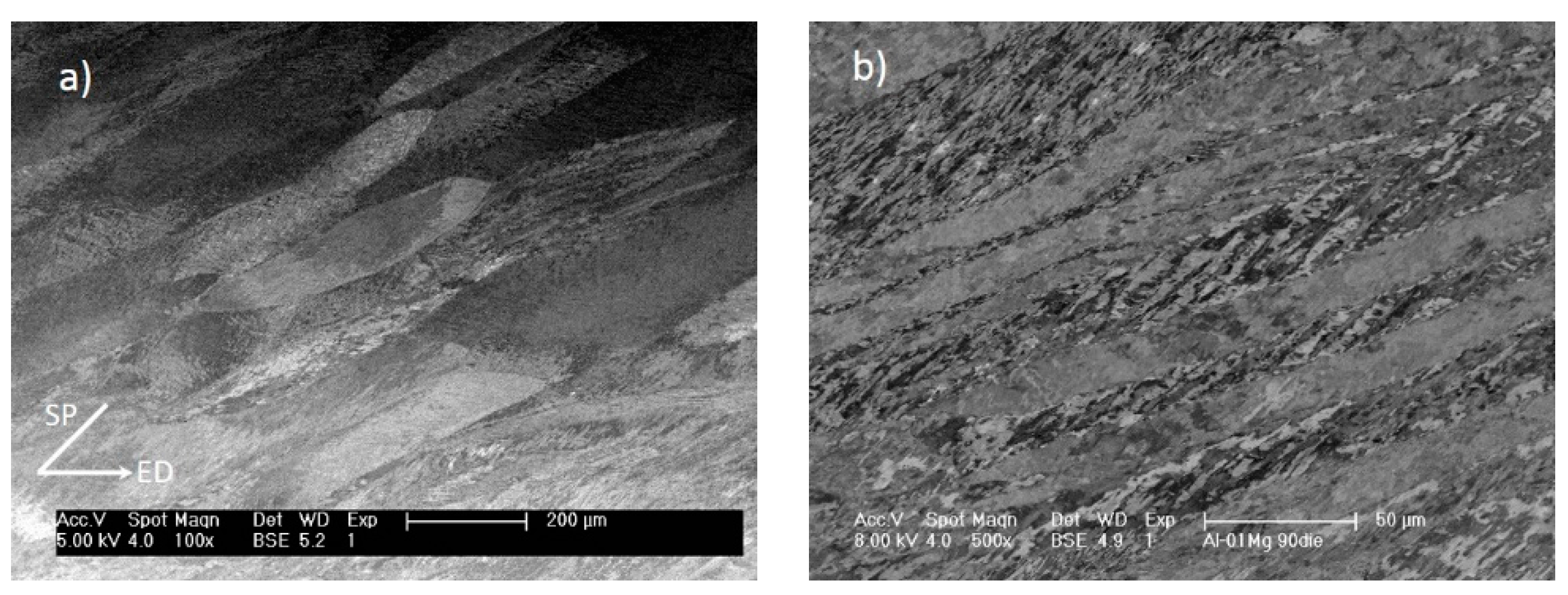
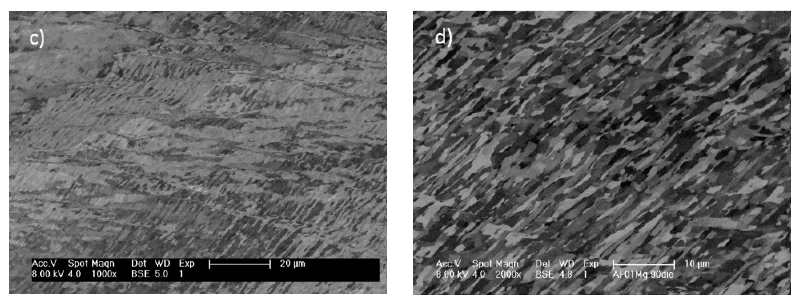
Figure 2 shows the characteristic microstructures of the material at various scales after one pass ECAE with the 90° die. It is seen that initial grains are elongated in response to the strain applied (Figure 2a). Deformation banding took place due to orientation splitting and deformation bands with either regular slab-like shapes at a scale close to the average grain size (Figure 2b) or irregular geometry (Figure 2c) at a finer scale have formed. At the finest scale, dislocation cell bands are the most distinctive microstructural feature (Figure 2d). The substructural alignment was examined with respect to the deformation geometry and crystallographic orientations of individual grains. It was found that the overall elongation direction of the fine scale substructure is generally within ±5° of the die shear plane. The variation may occur within a grain but mostly across boundaries. The highest variation was found in the area where severe irregular deformation banding took place and the deviation from the die shear plane could be as high as 15°. Figure 4a shows the distribution of the inclination angle to the extrusion direction measured from 50 grains in the centre of the sample. The elongation direction of individual cells is in line with the substructural alignment direction they are in, although the direction of some cells is more diverse than the overall substructure. Figure 3 shows a statistical distribution of cell band alignment direction relative to the extrusion direction, based on image analysis, and it is clear from the figure that dislocation cell bands are strongly aligned with the die shear plane, i.e., at approximately 45° to the extrusion direction. The average misorientation across the cell bands, where they did not coincide with other features of the deformation structure that superimposed strong local orientation gradients, were ~4.1°. This suggests that cell bands did not generate new high angle boundaries. Aligned cell bands were found to have formed in all the grains throughout the billet and continue within deformation bands, with a clear correlation to the dies shear plane as described above. Figure 4 shows an example of die shear plane aligned cell band structure aligned across a few grains in an EBSD map (Figure 4a) and the orientations of the individual grains in a (111) pole figure (Figure 4b), demonstrating that the cell bands are closely aligned in the die shear plane regardless of the orientation of individual grains. It should be noted, however, that plastic flow tended to bring primary slip planes of {111} into the die shear plane. This is similar to the texture development during rolling in which {111} planes tend to rotate and coincide with the rolling plane.
3.2. Structural Evolution in the 2nd Pass
In the 2nd pass of ECAE, although the original grain structure continues to distort in proportion to the shear strain with route A, there is always a strain path change depending on die angle and processing route. This involves a rotation of the idealized shear plane and the activation of latent slip systems, except for route C, which represents a Bauschinger type reversal. For route A used in this investigation, the theoretical shear plane alternates by π-2φ every cycle and should thus intercept the cell bands from the 1st pass by 90°. Such strain path changes are known to promote shear banding as the collapse of the lamellar cell bands, when subjected to an orthogonal shear on new slip systems, can lead to transient flow softening [18].
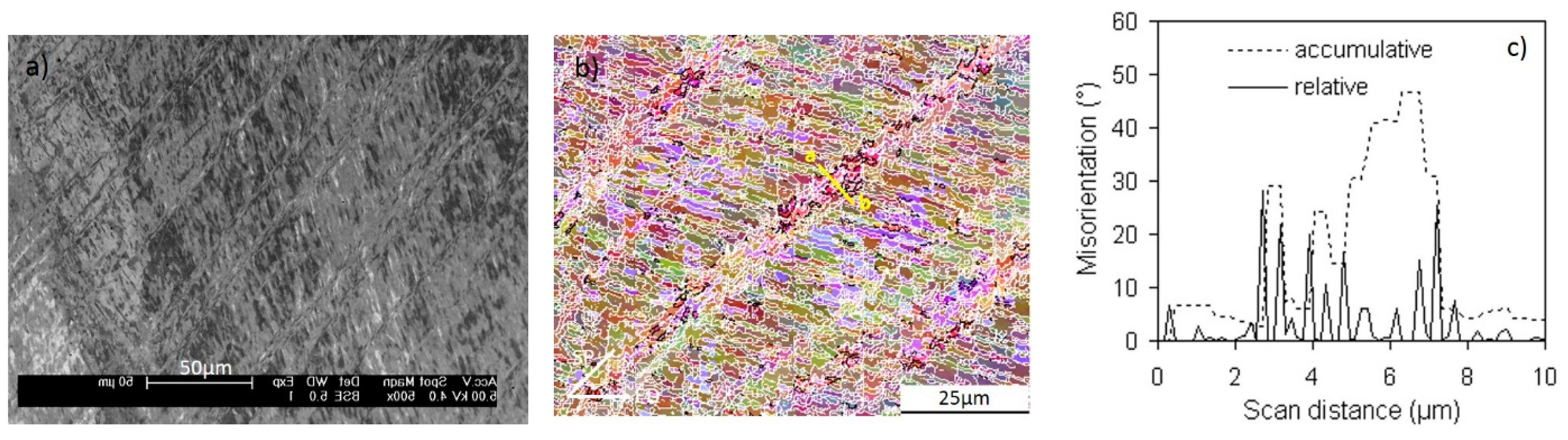
As expected, it was found that microshear banding parallel to the die shear plane dominated the deformation structure in the 2nd pass. Figure 5 shows shear bands formed in the 2nd pass cutting through the aligned cell band structure developed in the 1st pass. The shear bands were always aligned closely with the die shear plane across the whole sample, and are, therefore, not crystallographically orientated. Some shear bands were only one cell wide, but many were seen in packets of 2–5 bands and even extended across grain boundaries (Figure 5).
EBSD measurements showed that shear bands generated a significant orientation spread along the ND-ED great circle in the (111) pole figures, as a result of rotation around the transitional direction (TD) towards ED, relative to the matrix. The overall lattice rotation was generally in the range of 6 to 30° and in some cases reached 50°, which readily generated new high angle boundary (HAB) segments across the microshear band boundaries as can be seen from the misorientation linescan in Figure 5c (along line ab in Figure 5b). Given that the shear bands are relatively closely spaced, they are an important source of new HAB generation, which benefit from the strain path change during ECAE processing.
3.3. Lamellar Fibre Structure in the 3rd Pass
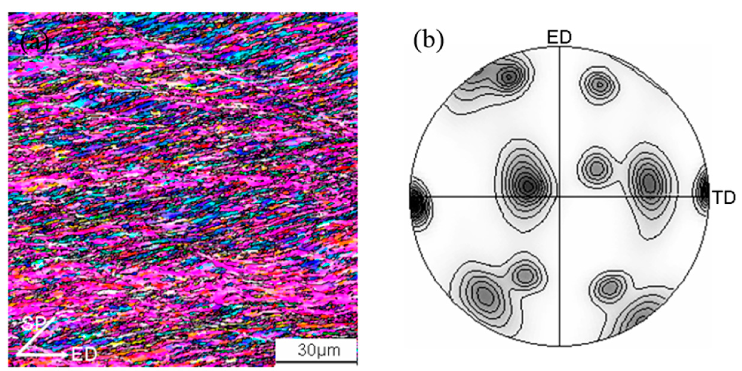
The fraction of HABs was found to have increased considerably after the 3rd pass. These HABs were predominantly aligned and formed a fibre structure, as shown in Figure 6a. EBSD results showed that the fraction of HABs reached 30% with an average spacing of 1.65 μm. The overall spacing of HABs and low angle boundary (LABs) across the fibre structure was 0.67 µm. The fibre structure was aligned at about 12° to ED. This is in close agreement with the theoretically expected values between the grain elongation direction and the ED (β), which is 9.5° for a 90° die, calculated according to the relationship
where n is the number of ECAE passes and is the total shear strain in the die shear plane after n passes. This suggests that the formation of the fibre structure was primarily a result of rigid structuralrotation, which is related to the non-symmetric material spin in simple shear deformation, and compression of the prior HABs in response to the total macroscopic shear strain. The overall fibre structure textures were determined from EBSD measurements over an area of ~500 × 500 µm, and were found to be dominated by {431}<527> component in the ECAE reference frame, as shown in Figure 6b or {111}<110> in the dis shear plane (x’y’z’) frame.
A detailed description of the deformation structure evolution to higher strains with route A is beyond the scope of this work, and has been previously been described in general terms [19,20]. Briefly, at larger strains, the HABs become dominant and the fibre boundary spacing approaches one subgrain in width, forming high aspect ratio “ribbon” grains with variable lengths. Further refinement then occurs through shortening of the ribbon grains by transverse LABs developing higher misorientations, and dynamic recovery [8,19,21]. Characteristically, the rate of increase in the fraction of HAB areas and the reduction in the average HAB spacing reduces greatly after the 3rd pass. In the meantime, the effect of crystallographic features on structural evolution became less important.
4. Discussion
The evolution of deformation structure during early stages of ECAE, for up to three passes, has been investigated, with emphasis on the alignment of important features of the deformation structure and their spatial correlation to preferred crystallographic orientations. The development of these characteristic features and their relationship to the texture formation during ECAE processing is discussed below. It should be noted that the deformation mode in ECAE, which approximates to simple shear and the strain path change that causes the shear plane to alternate each pass with route A, leads to some unique features of the deformation structure development. When compared to more conventional processes like rolling and torsion, however, there are also many similarities.
4.1. General Features of Deformation Structure
The experimental results have shown that the aligned cell bands, deformation bands and microshear bands are the main characteristic deformation structure features developed during the early stages of ECAE. In the 1st pass, the deformation structure was characterised by features forming on a range of length scales from fine ~1 m wide aligned cell bands to 40 m large scale primary deformation bands, and at an intermediate level by regions dominated by finer irregular deformation bands. In comparison, the 2nd pass was characterised by the introduction of intense microshear bands, with little further development of cell band structure. In the 3rd pass, a fibrous structure emerged with the HABs becoming aligned and rotated in the direction of grain distortion, with the cell band structure being replaced by subgrains. Orientation splitting was found to be largely established within the 1st pass associated with deformation banding. In rolling and other deformation processes, primary deformation banding usually takes place rapidly at low strains [22] and the present work has evidently confirmed this feature in ECAE.
The generation of new HAB area occurred, by orientation splitting, shear banding and the extension of boundaries due to the imposed shear. Of these mechanisms at low strains, orientation splitting involving fine scale irregular deformation banding is probably the most significant source of grain refinement, whereas at high strains with route A, the extension of boundaries with strain is much more important as previously shown [9]. Shear banding, being dominant in the 2nd pass, also provided an important mechanism for grain subdivision. However, the relative importance of this mechanism is sensitive to material and deformation conditions. In this study shear banding became less significant once the cell band structure broken down and the HAB spacing substantially reduced. The development of new HAB area required for grain refinement is clearly a highly heterogeneous process, which is dependent on localised shear and orientation instability, rather than the gradual uniform rotation of a cellular structure.
4.2. Substructural Alignment
In his review paper, Winther [13] pointed out that although approximate macroscopic alignment generally occurred, precise crystallographic alignment with the most highly stressed slip plane was frequent. In ECAE, investigations have highlighted some crystallographic features of the deformation structures formed but none has yet shown convincing results to clarify this fundamental substructural alignment issue. For example, Fukuda and co-workers [12], proposed that the alignment of cell bands and shear bands was crystallographically related, based on an investigation with aluminium single crystals. However, in their work the micrographs show that the deformation zone was extremely wide and the deformation mode is thus unlikely to be a pure simple shear, making it difficult to know the direction of the maximum shear stress.
In the present work, cell bands formed in the 1st pass have been clearly identified to be aligned substantially within a deviation of ±10° with the die shear plane as shown in Figure 3, irrespective of individual grain orientations. In the 2nd pass, microshear bands also formed in alignment with the die shear plane (Figure 5a). Extensive microstructural examinations and EBSD measurements showed that cell bands and microshear bands were aligned with the die shear plane across the entire sample encompassing an unlimited amount of grains. Clearly they were macroscopically oriented in response to the maximum resolved shear stress in the die shear plane, rather than being crystallographically related. However, rotation of {111} planes towards the shear plane took place to facilitate dislocation slip, which increased the coincidence of planar dislocation boundaries with {111} slip planes in the deformation structure.
In rolling, the boundaries of aligned cell bands are transient features of the microstructure, which remain active and undergo continuous reorganisation during deformation, maintaining their alignment with respect to the deformation geometry [23]. These boundaries are the result of dynamic recovery of the dislocation debris produced during slip in which the dislocation walls are continually dissolving, reforming and re-orienting during deformation. In ECAE, however, the cell bands formed in the 1st pass were a permanent feature during the subsequent deformation pass. The change in strain path between passes suddenly realigns the cell bands relative to the shear plane, by φ-2π. For the 90° die this is equivalent to an orthogonal change in strain path and this dramatic change in the active slip systems results in the boundaries collapsing, which promotes shear banding; with no sign of reorganisation and reformation of the cell bands. The cell bands thus largely undergo a rigid body rotation in the 2nd pass, which removes their shear plane correspondence.
It has been recognized that the substructure formed in the 1st pass has a strong effect on the development of deformation structure in the following repetitive ECAE processing [8,24]. The study of the 3rd pass deformation structure showed that the generally reported fibre/lamellar structure formed at medium to high strains is the result of evolution and realignment of the 1st pass cell bands and the 2nd pass microshear bands, during which a significant amount of HABs developed. It should be noted that, although the boundaries generated by microshear bands have much higher average misorientations than cell band boundaries, the overall intensity of the latter is substantially higher. On average, the spacing of microshear bands is about 5 to 10 times of cell bands. Therefore, cell bands might have contributed more than microshear bands in structural refinement.
4.3. The Development of the Preferred Orientations and Their Effect on Deformation
The development of deformation textures in ECAE has previously been widely reported to be related to simple shear [3,9,25,26], although different authors have used either the shear plane or tool reference frame. Simulations have also been performed given reasonable agreement with experimental measurements [27]. Most authors have related the textures observed to the preferred orientations and A{111} and B<110> fibres seen in torsion tests. Simple shear occurs when direction of slip is in the plane of tilt. Coincidence between the crystallographic slip plane and the simple shear plane during ECAE not only allows the least number of slip systems to operate during deformation, but also requires less energy than non-crystallographically correlated shear. Therefore, once a crystallographic correlation is established, it tends to be maintained during subsequent deformation. For an idealised simple shear deformation path in ECAE, it is thus unsurprisingly to see the development of preferred orientations that provide the crystallographic coincidence with the die shear plane. However, deformation through most dies only approximates to a simple shear and frequently involves other strain components. Furthermore, simple shear textures tend to be relatively weak as, unlike in plane strain compression, there is a constant rigid body rotation which results in material element break away from preferred orientations.
The preferred orientations found in the present work were in agreement with the predictions of texture simulations using either full or relaxed constraints Taylor model [27,28,29] and bulk texture measurements findings [20,30]. The main texture components observed in the EBSD maps are summarised in Table 1. The orientation transformation from the ECAE die reference frame (ND-ED-TD), in which orientations are presented in the pole figures, to the idealised shear plane reference frame (x’y’z’, see Figure 1a) was carried out by an anticlockwise-rotation about TD of 45° for the 90° die.
As given in Table 1, common orientations on A{111} fibres A1 and A2 are equivalent to {111}<1-10> and {111}<11-2> components in the shear plane reference frame. B-type orientations in the shear plane reference frame, i.e., B1 {100}<01-1> developed with both dies, an additional different B-type orientation B2 developed with the 90° die, which was observed in a high fraction in the 3rd pass fibre structure. Furthermore, the {111}<110> orientation in the ECAE die reference frame, found to be often associated with deformation bands in both the 90° and 120° dies, rotates, to a “random” near {521}<012> and {113}<174> with the 90° and 120° die is in the shear plane reference frame.
The initial starting texture of the annealed Al-0.13Mg used in the present work was a recrystallised rolling texture, comprised primarily of weak P {110}<111> and ND-rotated cube {001}<012> components [31]. Grains of P {110}<111> texture require a rotation of 45° with the 90° die to be in the orientation parallel to the die shear plane, whereas grains of rotated cube {001}<012> orientation are only a few degrees away from B1, suggesting that the initial textures could contribute to the development of such texture in association with cell bands and irregular deformation bands. However, since the intensity of both P and rotated cube texture components was very low (less than 10% volume fraction in total), their contributions must be limited.
Shearing on A-type orientations occurs on a {111} plane, parallel to die shear plane. The ideal orientation is A1 with the 90° die with a <110> direction in the maximum resolved shear stress direction and Schmid factor of 1. However, A1 and A2 orientations were found to be equally dominant in the 1st pass. On the other hand, A2, despite being of a smaller Schmid factor of 0.82, was more frequently observed than A1 during shear banding in the 2nd pass. This could be due to that the A2 orientation contains two <110> directions in the slip plane symmetrical about ED at ±35.26° and this allows two slip systems to operate simultaneously, which may result in a more stable orientation than single system dominated slip. The B<110> fibres contain a <110> direction aligned with the shearing direction –x’, although they have up to four (111) planes, which are at an angle to the die shear plane but parallel to the shear direction (–x’). Since the deformation zone is in reality a three dimensional volume with a near fan-shaped cross section on the ND-ED planes, the (111) planes of the B type orientations actually have a certain area of intersection with the deformation zone, which was found to have a dimension of ~1000–1500 μm, which is larger than the average grain size (~300 µm) in the present investigation. Thus slip on the B-type orientations was certainly possible and should be easier than on random orientations.
Upon strain path change, simple shear in the 2nd pass took place on new slip systems and the shear bands formed are seen to cut through the cell bands formed in the 1st pass, leading to a spread in orientation away from the matrix, whereas the matrix preferred orientations were still close to those expected from simple shear. The relative intensities of the A and B textures were different, with an increase in B type components relative to A. It is thus interesting to note that dominant starting A-type orientations in the shear plane reference frame developed in the 1st pass undergo an anticlockwise rotation of φ about Z’ relative to the shear plane in the 2nd pass. Because by symmetry there are several variants possible for each preferred orientation this readily realigns a close to a favourable stable orientation in the 2nd pass.
The development of preferred orientations certainly reduces the energy consumption for deformation. It also has effect on the deformation structure and contributes directly to the textures. It has been shown that the intensity of the aligned cell bands is higher in the grains with preferred orientations (in particular A-type) than other grains. This is not difficult to understand because (1) the crystallographic coincided slip has the benefit of higher Schmid factor and (2) the cell band boundaries formed tend to have the same Burgers vector, which reduces the chance for the boundaries dislocations to be annihilated during dynamic recovery as may occur to dislocations of different signs. In the case of shear banding, the coincidence between crystallographic slip systems with the die geometry should effectively “soften” the material under shear and promote strain localisation.
4.4. Comparison with Torsion and Rolling
Simple shear in ECAE is basically one dimensional and symmetrical only to the central plane defined by ND-ED, whereas in torsion sample symmetry contains a rotation axis of infinite order and the simple shear is axial symmetrical, in which the orientation distribution is independent of rotation about the axis and textures are thus fibre textures [32]. Additionally, the simple shear direction changes constantly in torsion whereas in ECAE it remains constant and deformation occurs in a narrow region along the die shear plane. The coincidence of characteristic orientations between the two deformation modes was rather likely due to the fact that dislocations in fcc metals can only glide on (111) planes and in <110> directions. It is expected that coincidence between crystallographic slip systems and the deformation geometry should be less common in rolling than in ECAE because the dominant deformation mode in rolling is pure shear. In pure shear, no frames of reference remain unchanged, although directions of greatest compression and extension are constant. This means that with any increment of strain the crystallographic planes will rotate. In rolling, no stable crystallographic relationship with respect to the maximum resolved shear direction, or the principle shear direction, is maintained and more slip systems must operate to retain the continuity of material and cross-slip has to take an essential part during deformation in the fcc type of materials. This is in agreement with observations by Humphreys and co-workers [33].
5. Conclusions
Simple shear along the die shear plane was the dominant deformation mode. The aligned cell bands and shear bands, both being closely aligned in the die shear plane, are the most characteristic deformation structures for both the 1st and 2nd pass ECAE. The 3rd pass deformation was characterized with the formation of a fibre structure with a significant fraction of high angle boundaries. Deformation banding occurred in the 1st pass due to orientation splitting and two types of deformation bands—primary and irregular, were observed and both developed high angle boundaries. No further deformation banding was observed in the 2nd and 3rd pass.
Cell bands and microshear bands generated during deformatin were aligned to the maximum shear stress plane, i.e., die shear plane, regardless of the crystallographic slip planes of individual grains.
Despite that simple shear was non-crystallographically related in principle, a significant fraction of material developed preferred orientations during deformation that allowed the coincidence between the crystallographic slip systems and the simple shear geometry to occur. The aligned cell bands formed in the 1st pass exhibited a permanent nature and evolved into the fibre structures in the 3rd pass, with certain amount of boundaries developed high misorientations. The 2nd pass shear bands were primarily microshear bands and contained a certain fraction of high misorientation boundary segments upon formation and formed an important part of the 3rd pass fibre structure.
The developed preferred orientations showed a crystallographic relationship with the simple shear geometry—having a (111) plane parallel to the die shear plane, which resulted in the development of A type textures, although B type textures were also observed with only slip directions in the dis shear plane.
Acknowledgments
The author would like to acknowledge the financial support from EPSRC Light Alloys Portfolio Partnership (EP/D029201/1) for this project and the helpful discussion with Professor P.B. Prangnell.
Author Contributions
The work is done solely by the author.
Conflicts of Interest
The author declares no conflict of interest.
References
- Segal, V.M.; Reznikov, V.I.; Drobyshevskiy, A.E.; Kopylov, V.I. Simple shear in equal channel angular extrusion. Russian Metallurgy. Engl. Transl. 1981, 1, 99–107. [Google Scholar]
- Segal, V.M. Materials processing by simple shear. Mater. Sci. Eng. A 1995, 197, 157–164. [Google Scholar] [CrossRef]
- Gholinia, A.; Prangnell, P.B.; Markushev, M.V. The effect of strain path on the development of deformation structures in severely deformed aluminium alloys processed by ECAE. Acta Mater. 2000, 48, 1115–1130. [Google Scholar] [CrossRef]
- Casati, R.; Fabrizi, A.; Tuissi, A.; Xia, K.; Vedani, M. ECAP consolidation of Al matrix composites reinforced with in-situ γ-Al2O3 nanoparticles. Mater. Sci. Eng. A 2015, 648, 113–122. [Google Scholar] [CrossRef]
- Valiev, R.Z.; Islamgaliev, R.K.; Alexandrov, I.V. Bulk nanostructured materials from severe plastic deformation. Prog. Mater. Sci. 2000, 45, 103–189. [Google Scholar] [CrossRef]
- Segal, V.M. Equal Channel angular extrusion: From macromechanics to structure formation. Mater. Sci. Eng. A 1999, 271, 322–333. [Google Scholar] [CrossRef]
- Segal, V.M. Engineering and commercialization of equal channel angular extrusion (ECAE). Mater. Sci. Eng. A 2004, 386, 269–276. [Google Scholar] [CrossRef]
- Prangnell, P.B.; Bowen, J.R.; Apps, P.J. Ultrfine grain structures in aluminium alloys by severe deformation processing. Mater. Sci. Eng. A 2004, 375–377, 178–185. [Google Scholar] [CrossRef]
- Huang, Y.; Prangnell, P.B. Orientation splitting and its contribution to grain refinement during equal channel angular extrusion. J. Mater. Sci. 2008, 43, 7273–7279. [Google Scholar] [CrossRef]
- Zhang, D.; Li, S. Orientation dependencies of mechanical response, microstructure and texture evolution of AZ31 magnesium alloy processed by equal channel angular extrusion. Mater. Sci. Eng. A 2011, 528, 4982–4987. [Google Scholar] [CrossRef]
- Sitdikov, O.; Avtokratova, E.; Sakai, T. Microstructural and texture changes during equal channel angular pressing of an Al-Mg-Sc alloy. J. Alloy. Comp. 2015, 648, 195–204. [Google Scholar] [CrossRef]
- Fukuda, Y.; Oh-ishi, K.; Furukawa, M.; Horita, Z.; Langdon, T.G. Influence of crystal orientation on ECAP of aluminium single crystals. Mater. Sci. Eng. A 2006, 420, 79–86. [Google Scholar] [CrossRef]
- Winther, G. Slip patterns and preferred dislocation boundary planes. Acta Mater. 2003, 51, 417–429. [Google Scholar] [CrossRef]
- Hurley, P.; Humphreys, F.J.; Bate, P. An objective study of substructural boundary aliognment in aluminium. Acta Mater. 2003, 51, 4737–4750. [Google Scholar] [CrossRef]
- Winther, G.; Juul Jensen, D.; Hansen, N. Dense dislocation walls and microbands aligned with slip planes—Theoretical considerations. Acta Mater. 1997, 45, 5059–5068. [Google Scholar] [CrossRef]
- Haldar, A.; Huang, X.; Leffers, T.; Hansen, N.; Ray, R.K. Grai orientation dependence of microstructures in a warm rolled IF steel. Acta Mater. 2004, 52, 5405–5418. [Google Scholar] [CrossRef]
- Humphreys, F.J.; Bate, P. Measuring the alignment of low angle boundaries formed during deformation. Acta Mater. 2006, 54, 817–829. [Google Scholar] [CrossRef]
- Ferrasse, F.; Segal, V.M.; Hartwig, T.K.; Goforth, R.E. Microstructure and properties of copper and aluminium alloy 3003 heaviely worked by equal angular extrusion. Metall. Mater. Trans. A 1997, 28, 1047–1057. [Google Scholar] [CrossRef]
- Apps, P.J.; Bowen, J.R.; Prangnell, P.B. The effect of coarse second-phase particles on the rate of grain refinement during severe deformation processing. Acta Mater. 2003, 51, 2811–2822. [Google Scholar] [CrossRef]
- Etter, A.L.; Baudin, T.; Rey, C.; Penelle, R. Microstructural and texture characterization of copper processed by ECAE. Mater. Char. 2006, 56, 19–25. [Google Scholar] [CrossRef]
- Prangnell, P.B.; Huang, Y.; Berta, M.; Apps, P.J. Mechanisms of formation of submicron grain structures by severe deformation. Mater. Sci. Forum 2007, 550, 159–168. [Google Scholar] [CrossRef]
- Kuhlmann-Wilsdorf, D. Q: Dislocations structures—How far from equilibrium? A: Very close indeed. Mater. Sci. Eng. A 2001, 315, 211–216. [Google Scholar] [CrossRef]
- Humphreys, F.J.; Hatherly, M. Recrystallization and Annealing Phenomena, 2nd ed.; Pergamon Press: Oxford, UK, 2004; pp. 28–35. [Google Scholar]
- Longdon, T.G. The principles of grain refinement in equal channel angular extrusion. Mater. Sci. Eng. A 2007, 462, 3–11. [Google Scholar] [CrossRef]
- Zhilyaev, A.P.; Oh-ishi, K.; Raab, G.I.; McNelley, I.R. Influence of ECAP processing parameters on texture and microstructure of commercially pure aluminium. Mater. Sci. Eng. A 2006, 441, 245–252. [Google Scholar] [CrossRef]
- Kliauga, A.M.; Bolmaro, R.E.; Ferrante, M. The evolution of texture in an equal channel pressed aluminium AA1050. Mater. Sci. Eng. A 2015, 623, 22–31. [Google Scholar] [CrossRef]
- Li, S.; Gazder, A.; Beyerlein, I.J.; Davies, C.H.J.; Pereloma, E.V. Microstructure and texture evolution during equal channel angular extrusion of interstitial free steel—Effects of die angle and processing route. Acta Mater. 2007, 55, 1017–1032. [Google Scholar] [CrossRef]
- Beyerlein, I.J.; Lebensohn, R.A.; Tomé, C.N. Modelling texture and microstructure in the equal channel angular extrusion process. Mater. Sci. Eng. A 2003, 345, 122–138. [Google Scholar] [CrossRef]
- Signorelli, J.W.; Turner, P.A.; Sordi, V.; Ferrante, M.; Vieira, E.A.; Bolmaro, R.E. Computational simulation of texture and microstructure evolution in Al alloys deformed by ECAE. Scr. Mater. 2006, 55, 1099. [Google Scholar] [CrossRef]
- Pithan, C.; Hashimoto, T.; Kawazoe, M.; Nagahora, J.; Higashi, K. Microstructure and texture evolution in ECAE processed A5056. Mater. Sci. Eng. A 2000, 280, 62–68. [Google Scholar] [CrossRef]
- Gholinia, A.; Bate, P.; Prangnell, P.B. Modelling texture development during equal channel angular extrusion of aluminium. Acta Mater. 2002, 50, 2121–2136. [Google Scholar] [CrossRef]
- Canova, G.R.; Kocks, U.F.; Jonas, J.J. Theory of torsion texture dev elopement. Acta Metal. 1984, 32, 211–226. [Google Scholar] [CrossRef]
- Hurley, P.J.; Humphreys, F.J. Modelling the recrystallization in single phase aluminium. Acta Mater. 2003, 51, 3779–3793. [Google Scholar] [CrossRef]
Figure 1.
Schematic diagram illustrating (a) equal channel angular extrusion (ECAE) process and reference coordinates and (b) poles of (111) planes parallel to the dies shear plane in the 90° and 120° dies respectively in the (111) pole figure.
Figure 1.
Schematic diagram illustrating (a) equal channel angular extrusion (ECAE) process and reference coordinates and (b) poles of (111) planes parallel to the dies shear plane in the 90° and 120° dies respectively in the (111) pole figure.

Figure 2.
FEG-SEM back scattered images, showing features of characteristic deformation structures after the 1st pass with the 90° die: (a) overall elongated microstructure; (b) primary deformation bands; (c) secondary deformation bands; (d) aligned cell bands. ED—the extrusion direction; SP—the die shear plane.


Figure 3.
Distribution of cell band alignment angle relative to the extrusion direction (ED), showing that cell bands are substantially aligned with the die shear plane around 45° to ED.
Figure 3.
Distribution of cell band alignment angle relative to the extrusion direction (ED), showing that cell bands are substantially aligned with the die shear plane around 45° to ED.

Figure 4.
(a) EBSD map, showing the substructural alignment in grains of different orientations and (b) (111) pole figure, showing the orientations of the individual grains—after the 1st pass ECAE.
Figure 4.
(a) EBSD map, showing the substructural alignment in grains of different orientations and (b) (111) pole figure, showing the orientations of the individual grains—after the 1st pass ECAE.

Figure 5.
Characteristic features of shear bands formed in the 2nd pass; (a) FEGSEM backscatter image; (b) EBSD map and (c) a linescan of relative and accumulative boundary misorientations along ab in (b), demonstrating the generation of medium and high angle boundaries by shear banding.
Figure 5.
Characteristic features of shear bands formed in the 2nd pass; (a) FEGSEM backscatter image; (b) EBSD map and (c) a linescan of relative and accumulative boundary misorientations along ab in (b), demonstrating the generation of medium and high angle boundaries by shear banding.

Figure 6.
(a) EBSD map and (b) (111) pole figure, showing the formation of a fibre microstructure and textures developed after 3rd pass ECAE.
Figure 6.
(a) EBSD map and (b) (111) pole figure, showing the formation of a fibre microstructure and textures developed after 3rd pass ECAE.


Table 1.
A summary of the characteristic textures and associated microstructural features such as cell bands (CBs), primary deformation bands (1DBs) and secondary deformation bands (2DBs), and shear bands (SBs) and fibre structures (fibre) in both simple shear and ECAE reference systems x’y’z and xyz, including the related slip systems.
| Notation | Orientations {hkl}<uvw> | Slip Systems in SSRS | Schmid Factor | Structural Features | ||
|---|---|---|---|---|---|---|
| ECAERS | SSRS | Plane/θSP *1 | Direction/θSD *2 | |||
| A1 | (521)[01-2] (52-1)[012] | (111)[-110] (11-1)[-110] | (111)/0 (111)/0 | [-110]/0 [-110]/0 | 1 | CBs, SBs |
| A2 | (81-1)[1-44] | (111)[-1-12] | (111)/0 | [-101]/+35.26 [0-11]/−35.26 | 0.82 | CBs, 1DBs, SBs |
| B1 | (122)[-411] | (100)[01-1] | (11-1)/57.4 (1-11)/−57.4 | [011]/0 [011]/0 | ~0.56 | CBs, 2DBs |
| B2 | (341)[-527] (3-14)[57-2] | (112)[1-10] (121)[10-1] | (111)/+19.42 (111)/−19.42 | [1-10]/0 [10-1]/0 | ~0.94 | SBs, fibre |
*1 θSP—rotation angle of (111) plane away from the die shear pane about −x’; *2 θSD—rotation angle of <110> directions away from –x’ about y’ in the die shear plane.
© 2016 by the author; licensee MDPI, Basel, Switzerland. This article is an open access article distributed under the terms and conditions of the Creative Commons Attribution (CC-BY) license (http://creativecommons.org/licenses/by/4.0/).
Share and Cite
MDPI and ACS Style
Huang, Y. Substructural Alignment during ECAE Processing of an Al-0.1Mg Aluminium Alloy. Metals 2016, 6, 158. https://doi.org/10.3390/met6070158
AMA Style
Huang Y. Substructural Alignment during ECAE Processing of an Al-0.1Mg Aluminium Alloy. Metals. 2016; 6(7):158. https://doi.org/10.3390/met6070158
Chicago/Turabian StyleHuang, Yan. 2016. "Substructural Alignment during ECAE Processing of an Al-0.1Mg Aluminium Alloy" Metals 6, no. 7: 158. https://doi.org/10.3390/met6070158
Note that from the first issue of 2016, this journal uses article numbers instead of page numbers. See further details here.