Author Contributions
Conceptualization, Y.-I.P.; methodology, Y.-I.P.; validation, Y.-I.P.; formal analysis, J.-S.C.; investigation, J.-H.K.; writing—original draft preparation, J.-H.K.; writing—review and editing, Y.-I.P.; visualization, J.-S.C.; supervision, Y.-I.P.; project administration, Y.-I.P.; funding acquisition, Y.-I.P. All authors have read and agreed to the published version of the manuscript.
Funding
This work was supported by the Dong-A University research fund.
Institutional Review Board Statement
Not applicable.
Informed Consent Statement
Not applicable.
Data Availability Statement
The data presented in this study are available on request from the corresponding author.
Conflicts of Interest
The authors declare no conflict of interest.
References
- Englert, D.; Losos, A.; Raucci, C.; Smith, T. The Role of LNG in the Transition Toward Low- and Zero-Carbon Shipping; World Bank: Washington, DC, USA, 2021. [Google Scholar] [CrossRef]
- IMO. MSC. International Code for the Construction and Equipment of Ships Carrying Liquefied Gasses in Bulk (IGC Code); IMO: London, UK, 2014; Volume 391. [Google Scholar]
- Oh, D.; Song, S.; Kim, N.; Kim, M. Effect of Cryogenic Temperature on Low-Cycle Fatigue Behavior of AISI 304L Welded Joint. Metals 2018, 8, 657. [Google Scholar] [CrossRef] [Green Version]
- Niu, W.; Li, G.; Ju, Y.; Fu, Y. Design and analysis of the thermal insulation system for a new independent type B LNG carrier. Ocean Eng. 2017, 142, 51–61. [Google Scholar] [CrossRef]
- Gupta, S.; Singh, D.; Yadav, A.; Jain, S.; Pratap, B. A comparative study of 5083 aluminium alloy and 316L stainless steel for shipbuilding material. Mater. Today Proc. 2020, 28, 2358–2363. [Google Scholar] [CrossRef]
- De Menezes Netto, E.B.; Kliauga, A.M.; Plaut, R.L.; Padilha, A.F. A comparative study using three stainless steels types (austenitic, super-ferritic and duplex ferritic-austenitic) and three industrial nitrocarburizing processes (liquid, gaseous and plasma). In Proceedings of the 1st ASM International Surface Engineering Conference and the 13th IFHTSE Congress, Columbus, OH, USA, 7–10 October 2002. [Google Scholar]
- Kim, T.-W.; Kim, S.-K.; Park, S.-B.; Lee, J.-M. Design of Independent Type-B LNG Fuel Tank: Comparative Study between Finite Element Analysis and International Guidance. Adv. Mater. Sci. Eng. 2018, 2018, 1–14. [Google Scholar] [CrossRef] [Green Version]
- Jeong, H.-W.; Kim, T.-H.; Kim, S.-S.; Shim, W.J. Thermal analysis of insulation system for KC-1 membrane LNG tank. J. Ocean Eng. Technol. 2017, 31, 91–102. [Google Scholar]
- Park, M.-J.; Choi, B.-K.; Kim, Y. On the efficient time domain stress analysis for the rolling chock of an independent type LNG tank targeting fatigue damage evaluation. Mar. Struct. 2017, 53, 32–51. [Google Scholar] [CrossRef]
- Ryu, M.C.; Jung, J.H.; Kim, Y.S.; Kim, Y. Sloshing design load prediction of a membrane type LNG cargo containment system with two-row tank arrangement in offshore applications. Int. J. Nav. Archit. Ocean. Eng. 2016, 8, 1–17. [Google Scholar] [CrossRef] [Green Version]
- Kim, Y. Rapid response calculation of LNG cargo containment system under sloshing load using wavelet transformation. Int. J. Nav. Archit. Ocean. Eng. 2013, 5, 227–245. [Google Scholar] [CrossRef] [Green Version]
- Park, Y.I. Ultimate crushing strength criteria for GTT NO96 LNG carrier cargo containment system under sloshing load. Ocean Eng. 2019, 188, 106224. [Google Scholar] [CrossRef]
- Park, Y.I.; Lee, J.H. Buckling strength of GTT NO96 LNG Carrier cargo containment system. Ocean Eng. 2018, 154, 43–58. [Google Scholar] [CrossRef]
- Lin, Y.; Ye, C.; Yu, Y.-Y.; Bi, S.-W. An approach to estimating the boil-off rate of LNG in type C independent tank for floating storage and regasification unit under different filling ratio. Appl. Therm. Eng. 2018, 135, 463–471. [Google Scholar] [CrossRef]
- Heo, K.H.; Kang, W.S.; Park, B.Q. Consideration for IMO Type C Independent Tank Rule Scantling Process and Evaluation Methods. Spec. Issue Soc. Naval Archit. Korea 2017, 93–104. Available online: https://www.koreascience.or.kr/article/CFKO201729562508726.page (accessed on 13 October 2021).
- Yao, Y.; Zhongyun, G. The structure design of type-C independent tank on LNG ship. In Proceedings of the 2015 Word Congress on Advances in Structural Engineering and Mechanics, Incheon, Korea, 25–29 August 2015. [Google Scholar]
- Korean Register of Shipping. International Code for the Construction and Equipment of Ships Carrying Liquefied Gases in Bulk (IGC Code); KR: Busan, Korea, 2014. [Google Scholar]
- Mukhraiya, V.; Yadav, R.K.; Kori, S. Thermal conductivity analysis in various materials using composite wall apparatus. IJMET 2016, 7, 342–350. [Google Scholar]
- Dassault Systèmes Simulia Corp. Abaqus 6.14 Theory Manual; Dassault Systèmes Simulia Corp.: Irving, TX, USA, 2014. [Google Scholar]
- Hobbacher, A.F. Recommendations for Fatigue Design of Welded Joints and Components; Springer International Publishing: Cham, Switzerland, 2016. [Google Scholar] [CrossRef]
Figure 1.
Flow chart of structural integrity assessment for independent type-C cylindrical tank applied in this study.
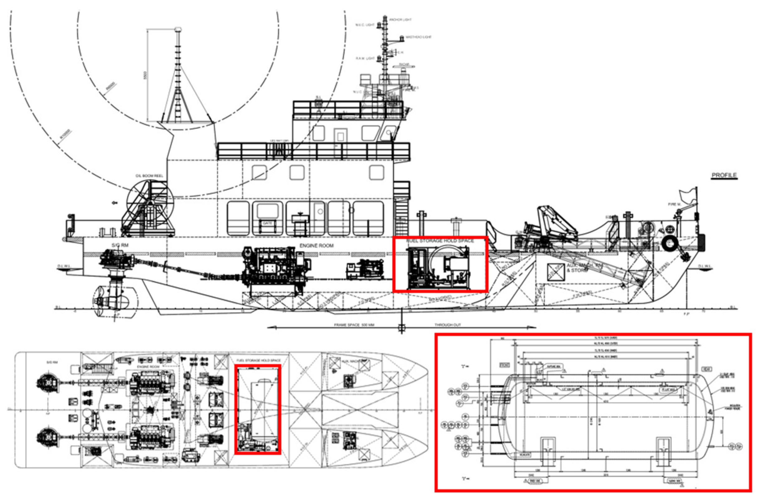
Figure 2.
General configuration of target ship and location of LNG fuel tank.
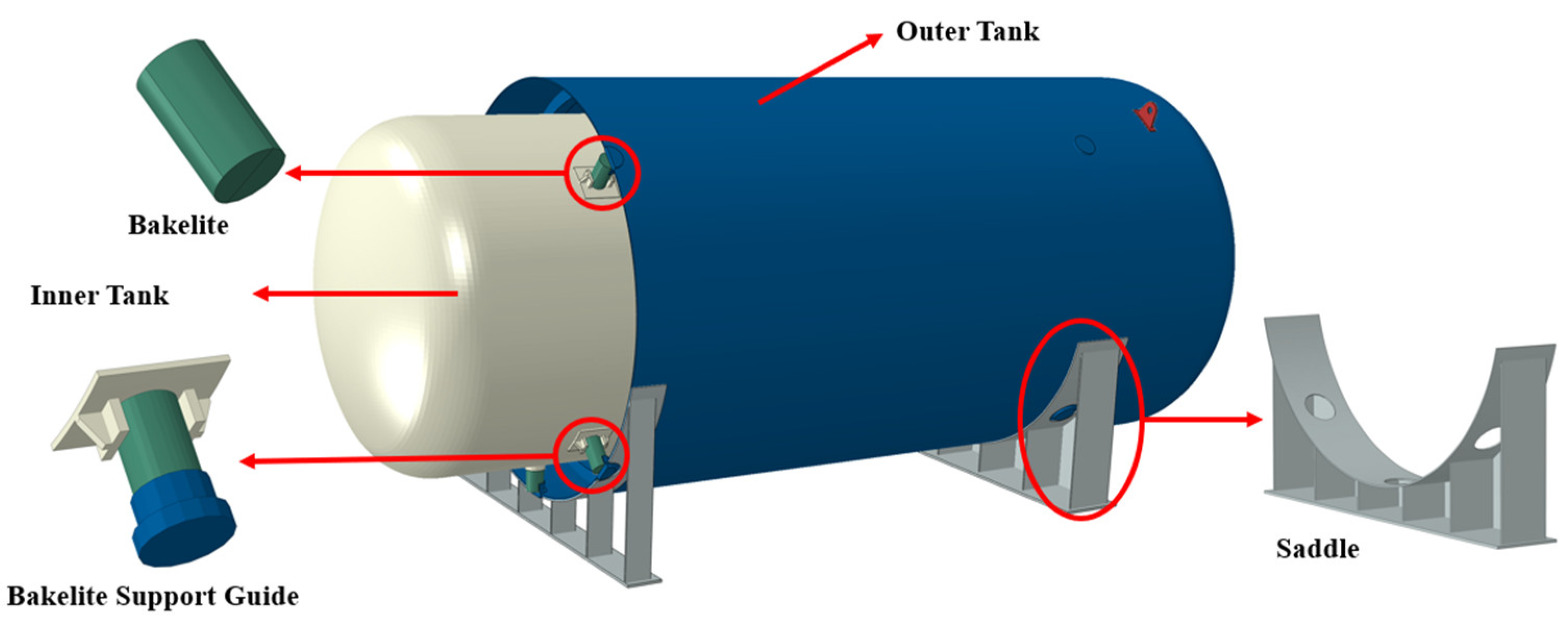
Figure 3.
Geometry of LNG fuel tank.
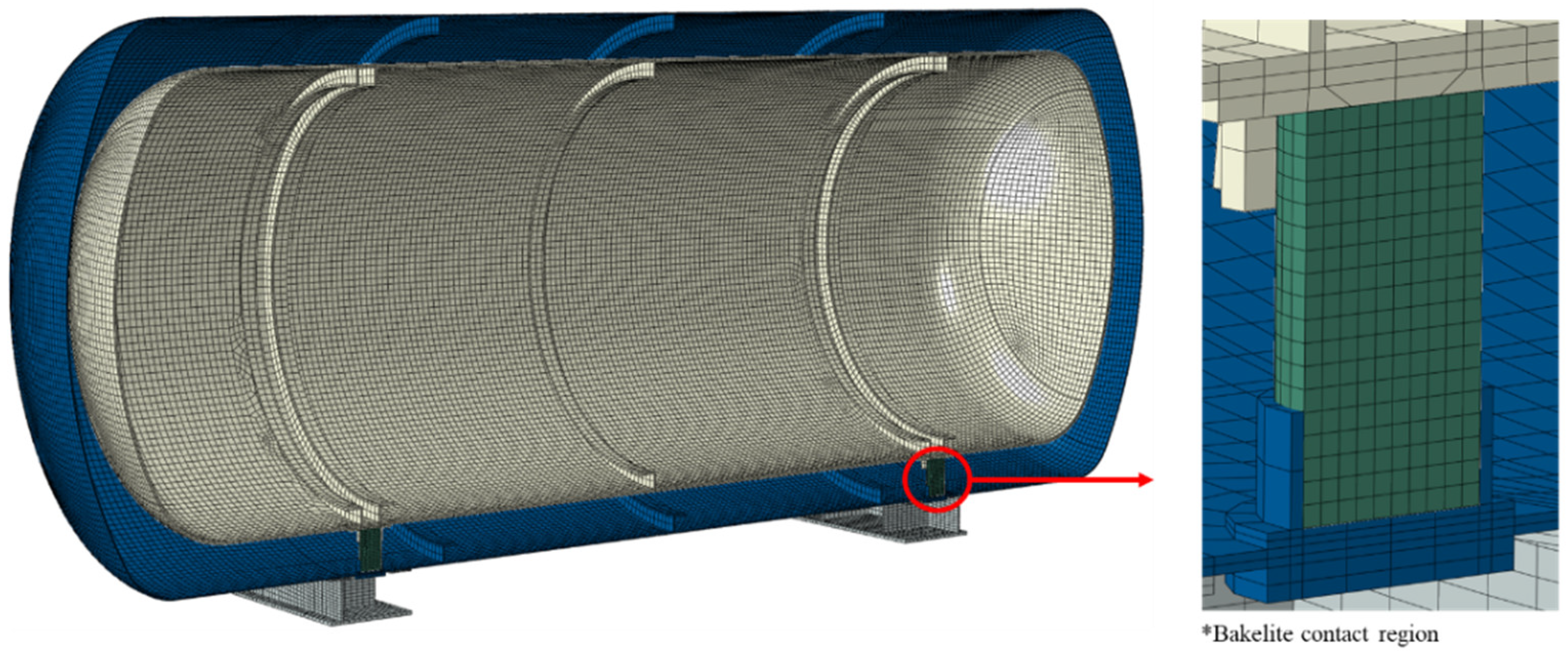
Figure 4.
Finite element model of LNG fuel tank.
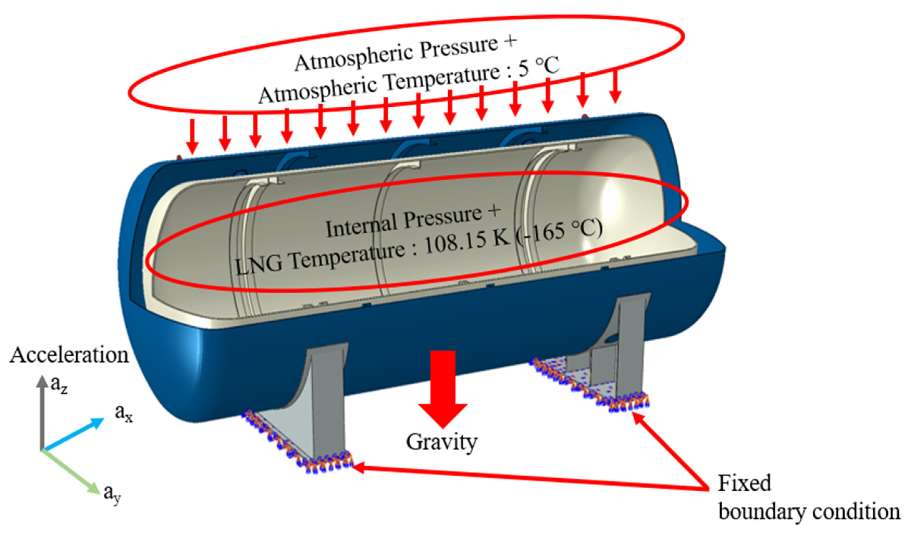
Figure 5.
Load and boundary condition for target FE model.
Figure 6.
Temperature distribution of inner tank (SUS304).
Figure 7.
Temperature distribution of inner tank (AL-5083-O).
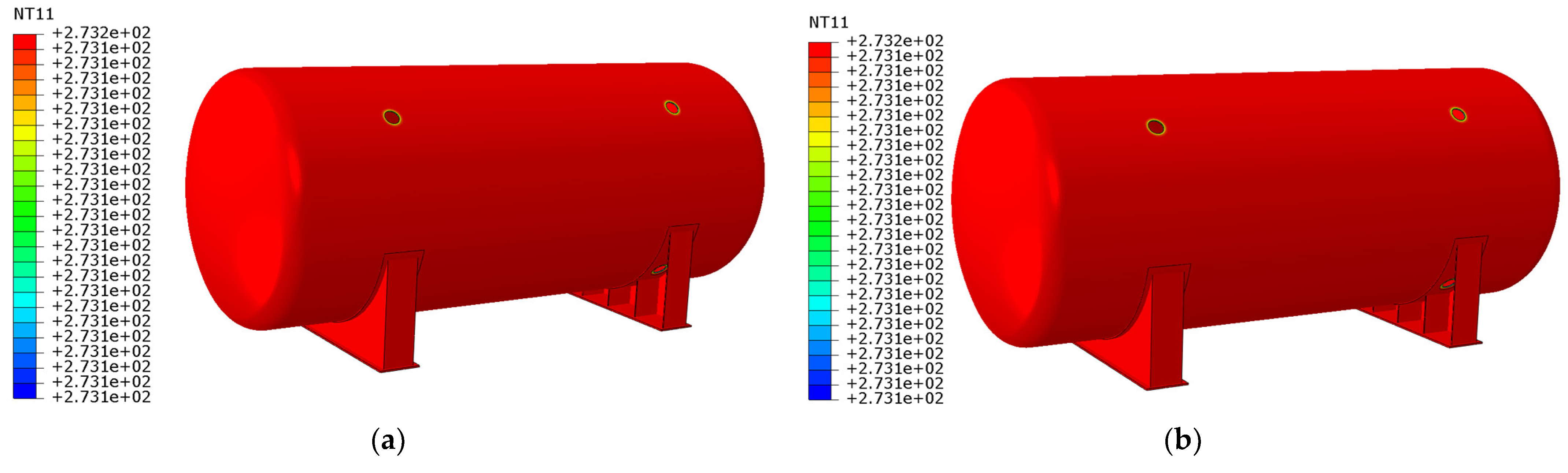
Figure 8.
Temperature distribution of outer tank: (a) SUS304; (b) AL-5083-O.
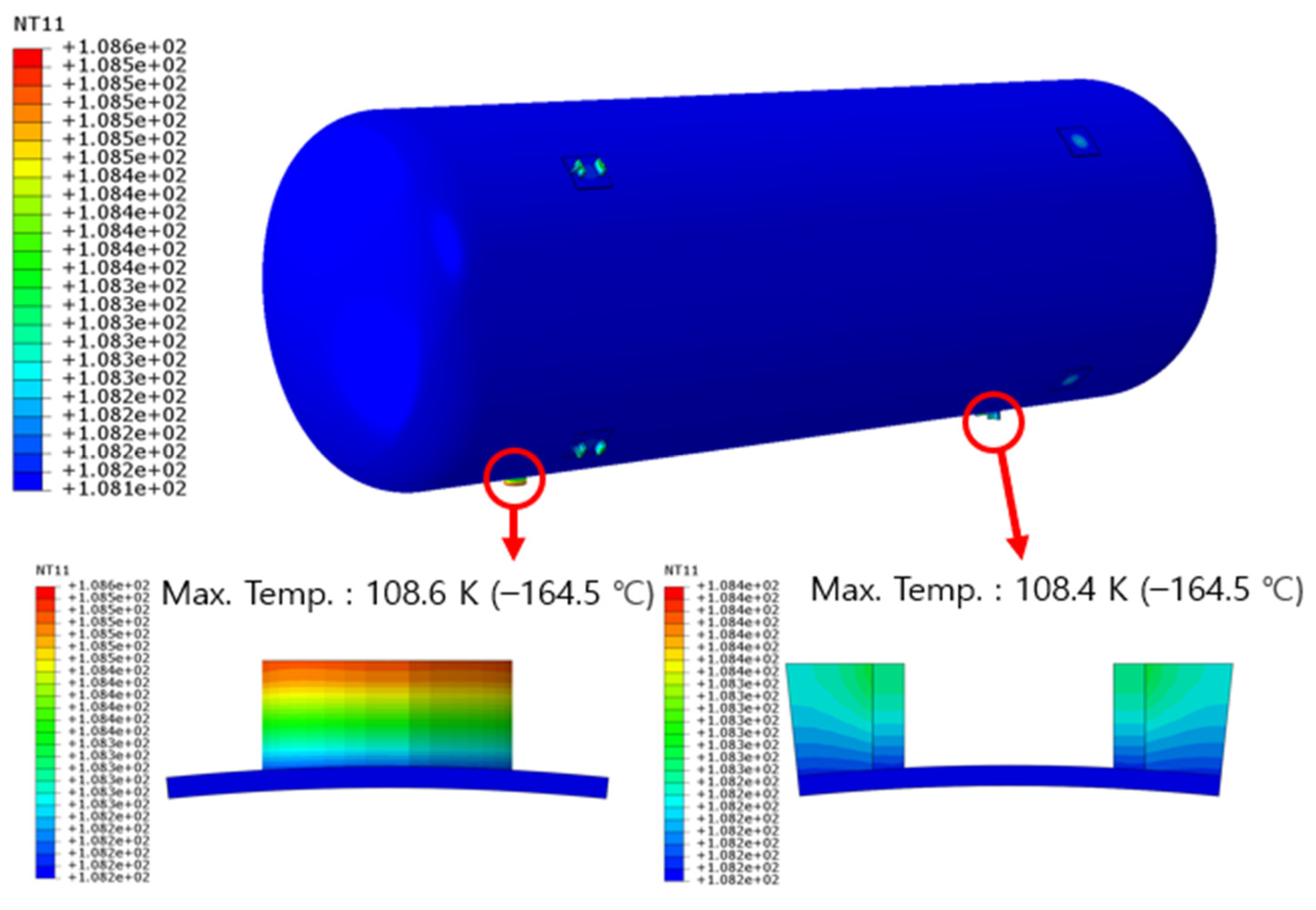
Figure 9.
Temperature distribution of Bakelite support: (a) SUS304; (b) AL-5083-O.
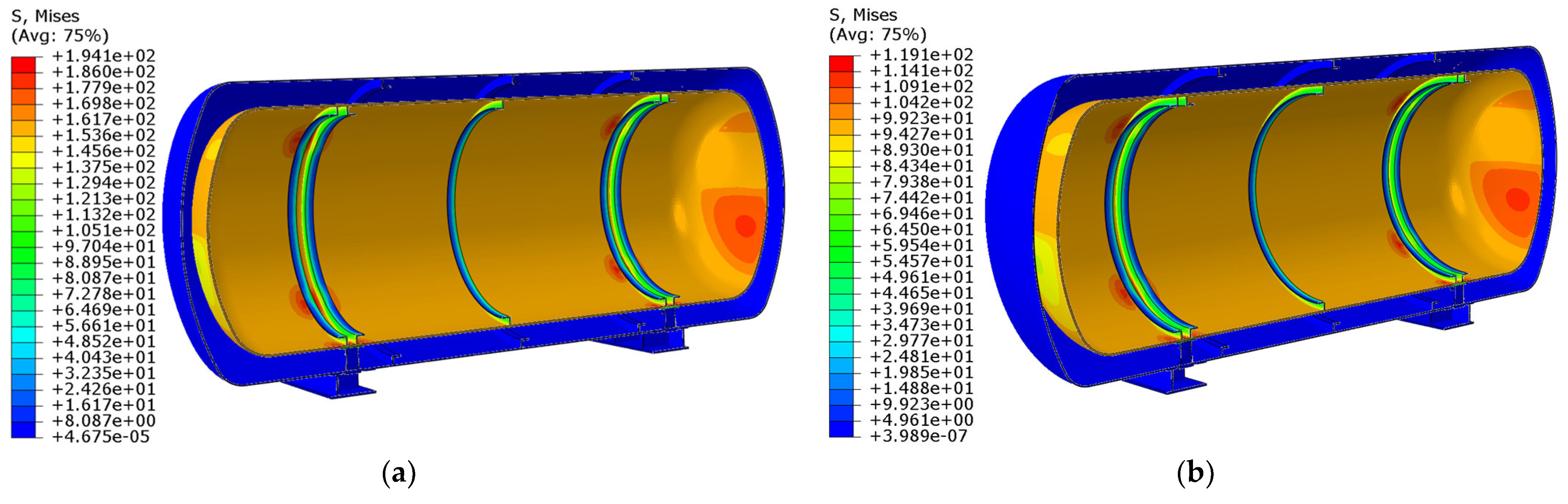
Figure 10.
Thermal stress distribution of LNG fuel tank: (a) SUS304; (b) AL-5083-O.
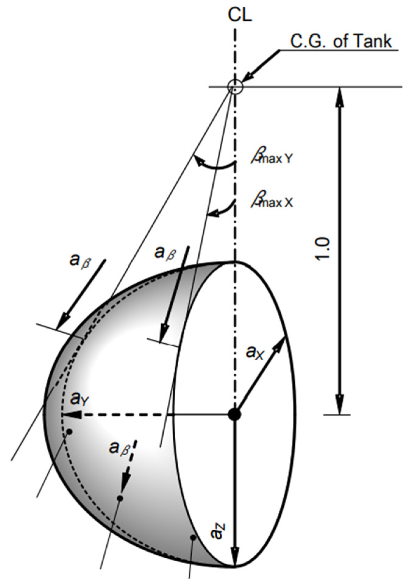
Figure 11.
Acceleration ellipsoid [
2].
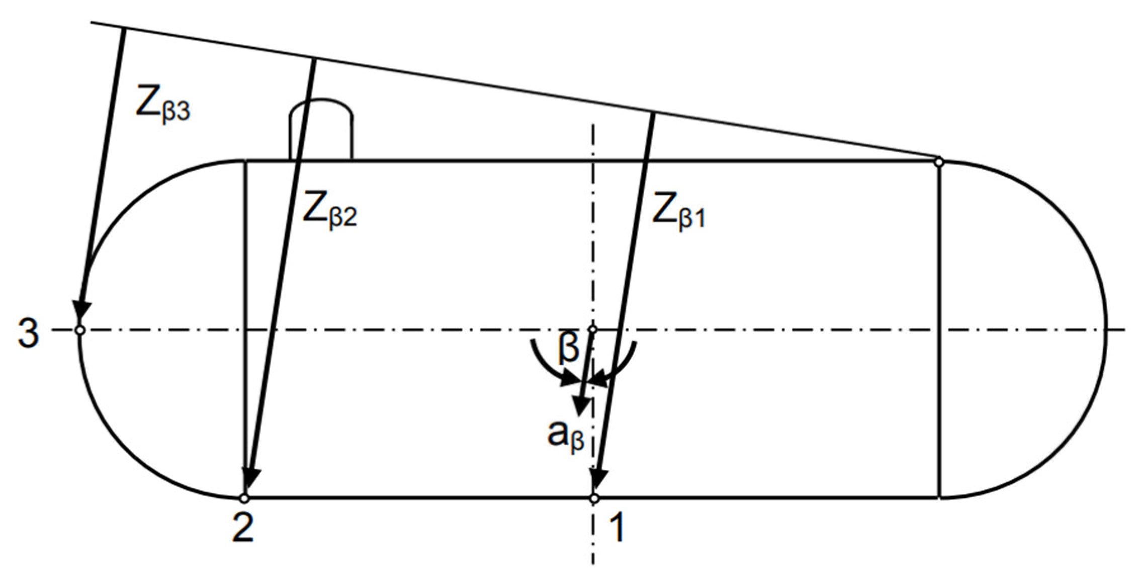
Figure 12.
Determination of Z
β [
2].
Figure 13.
Stress contour of strength evaluation in transverse acceleration (SUS304).
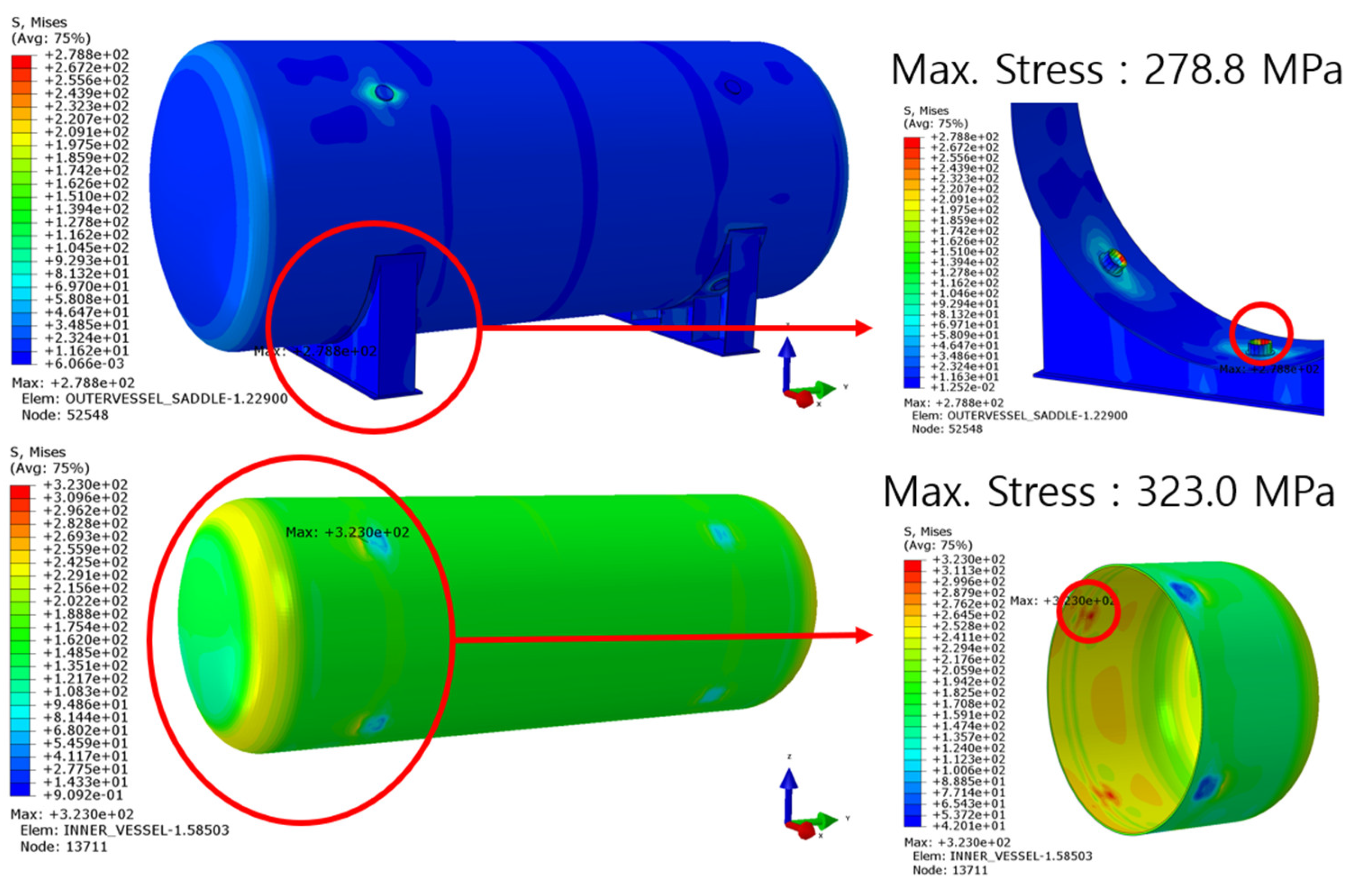
Figure 14.
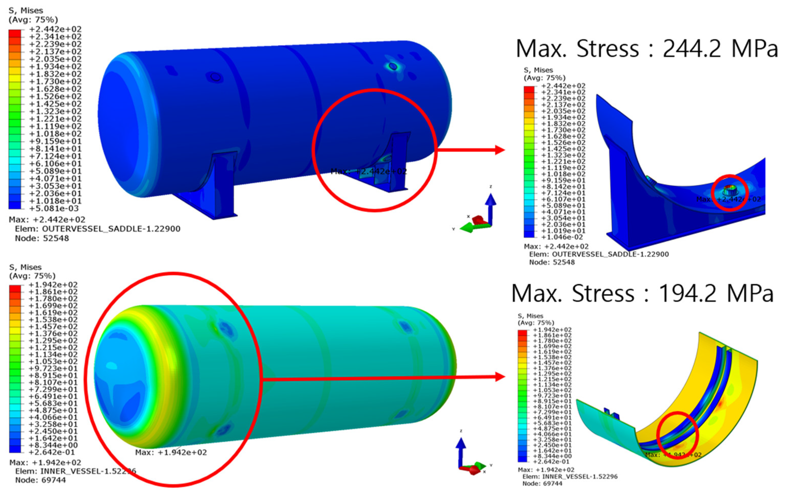
Stress contour of strength evaluation in transverse acceleration (AL-5083-O).
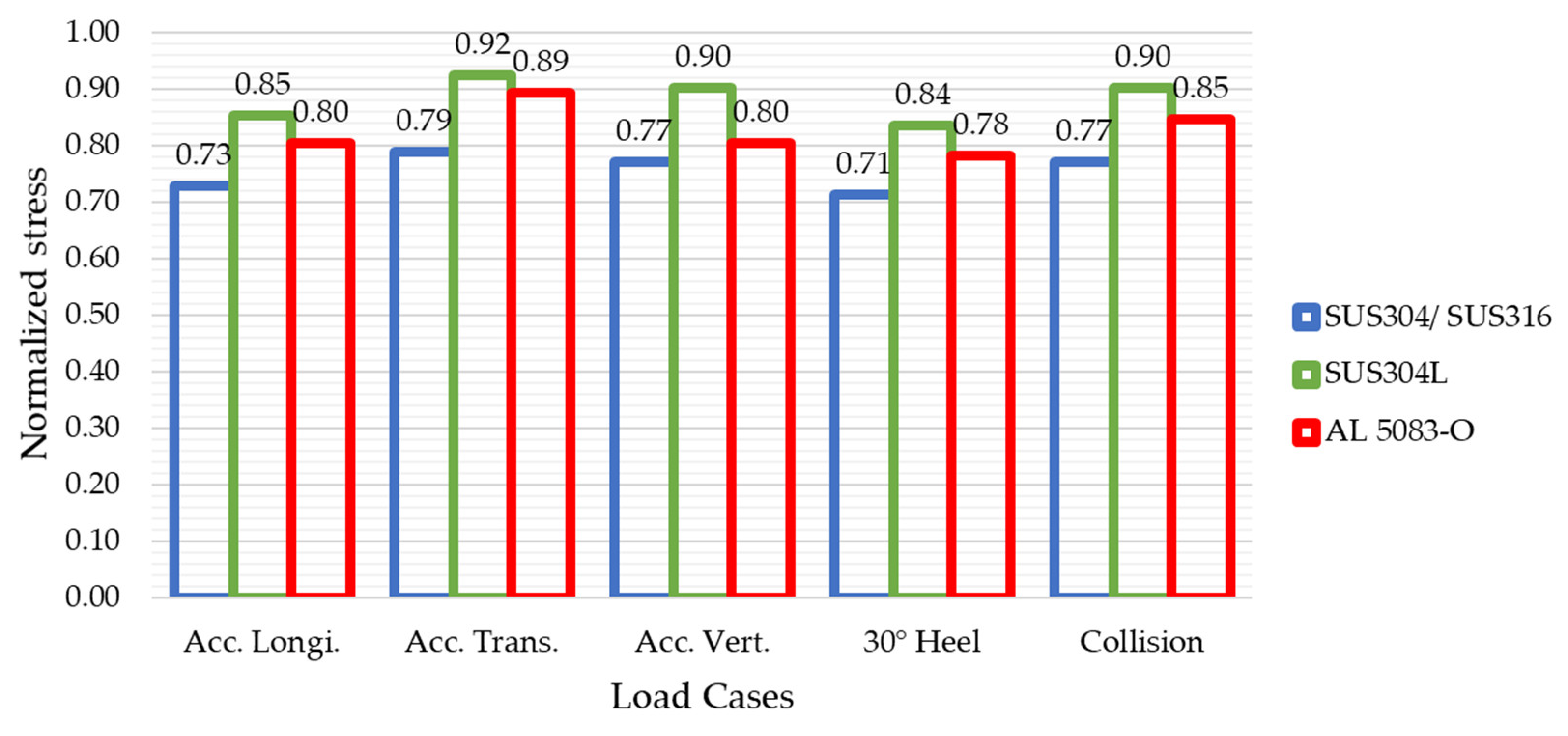
Figure 15.
Comparison of normalized stresses for different materials.
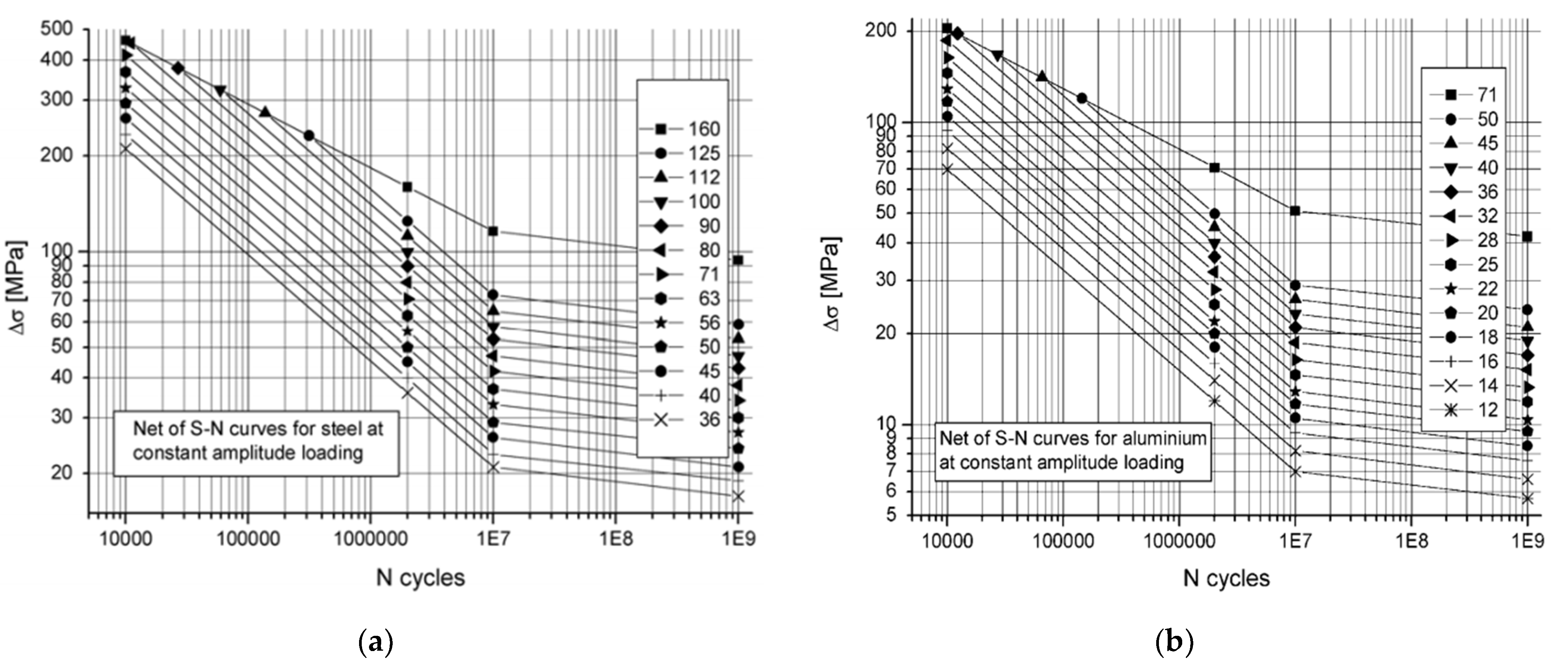
Figure 16.
S–N curves applied in this study: (
a) steel; (
b) aluminum [
20].
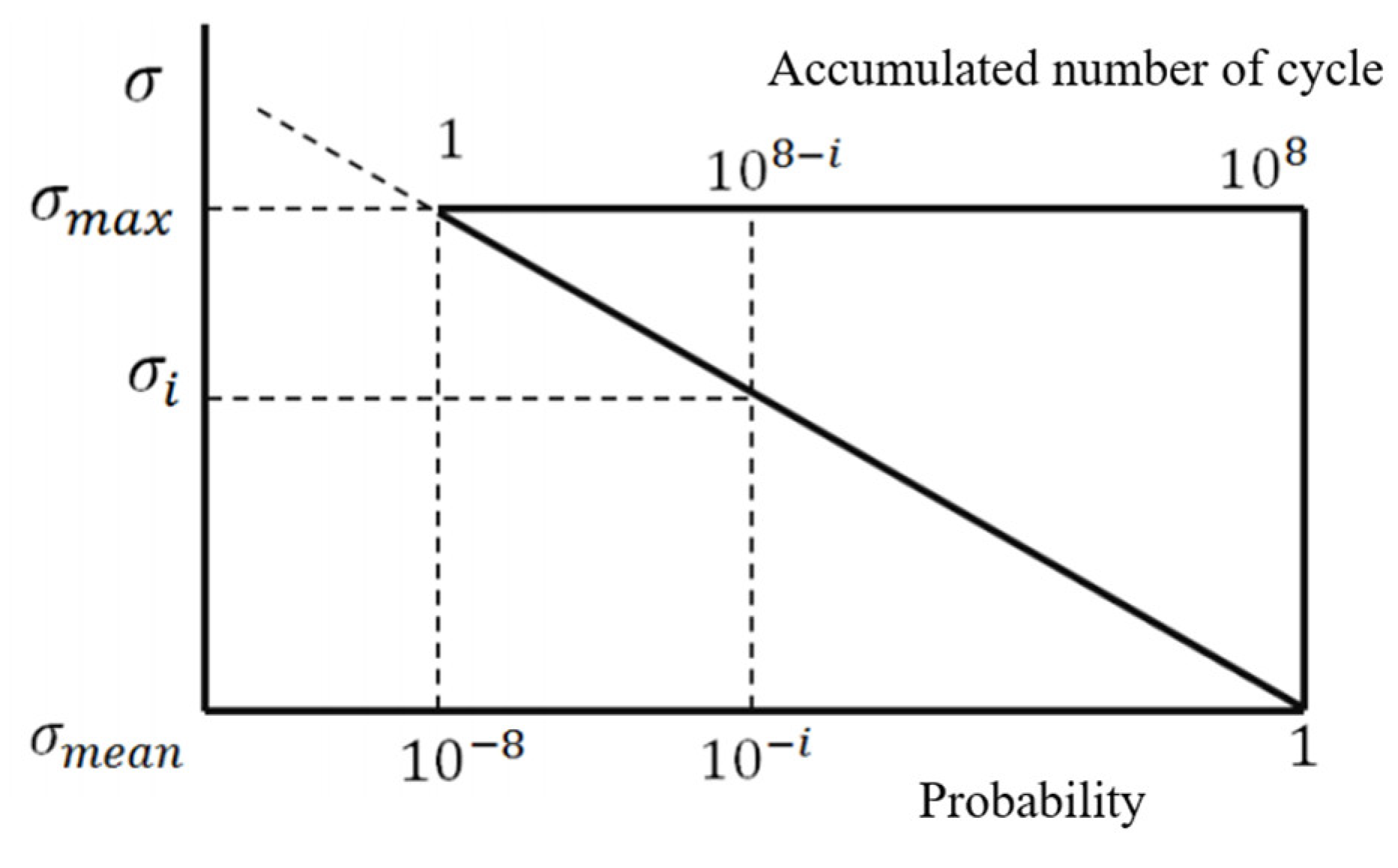
Figure 17.
Calculation of fatigue stress and number of cycles [
17].
Figure 18.
Stress contour in longitudinal acceleration condition for fatigue evaluation: (a) SUS304; (b) AL-5083-O.
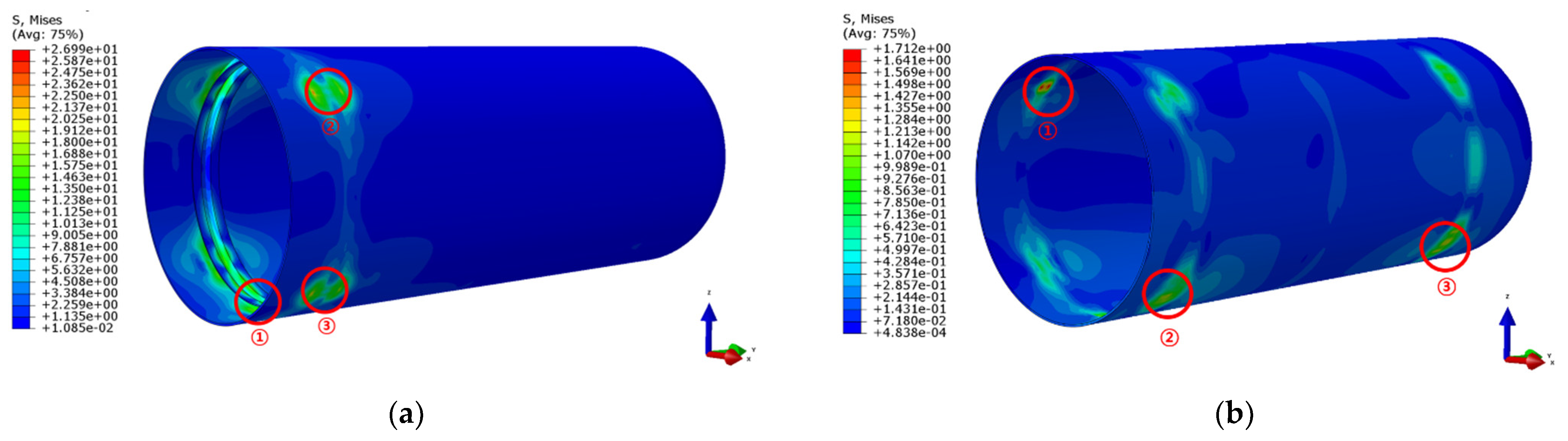
Figure 19.
Stress contour in full-load condition for fatigue evaluation: (a) SUS304; (b) AL-5083-O.
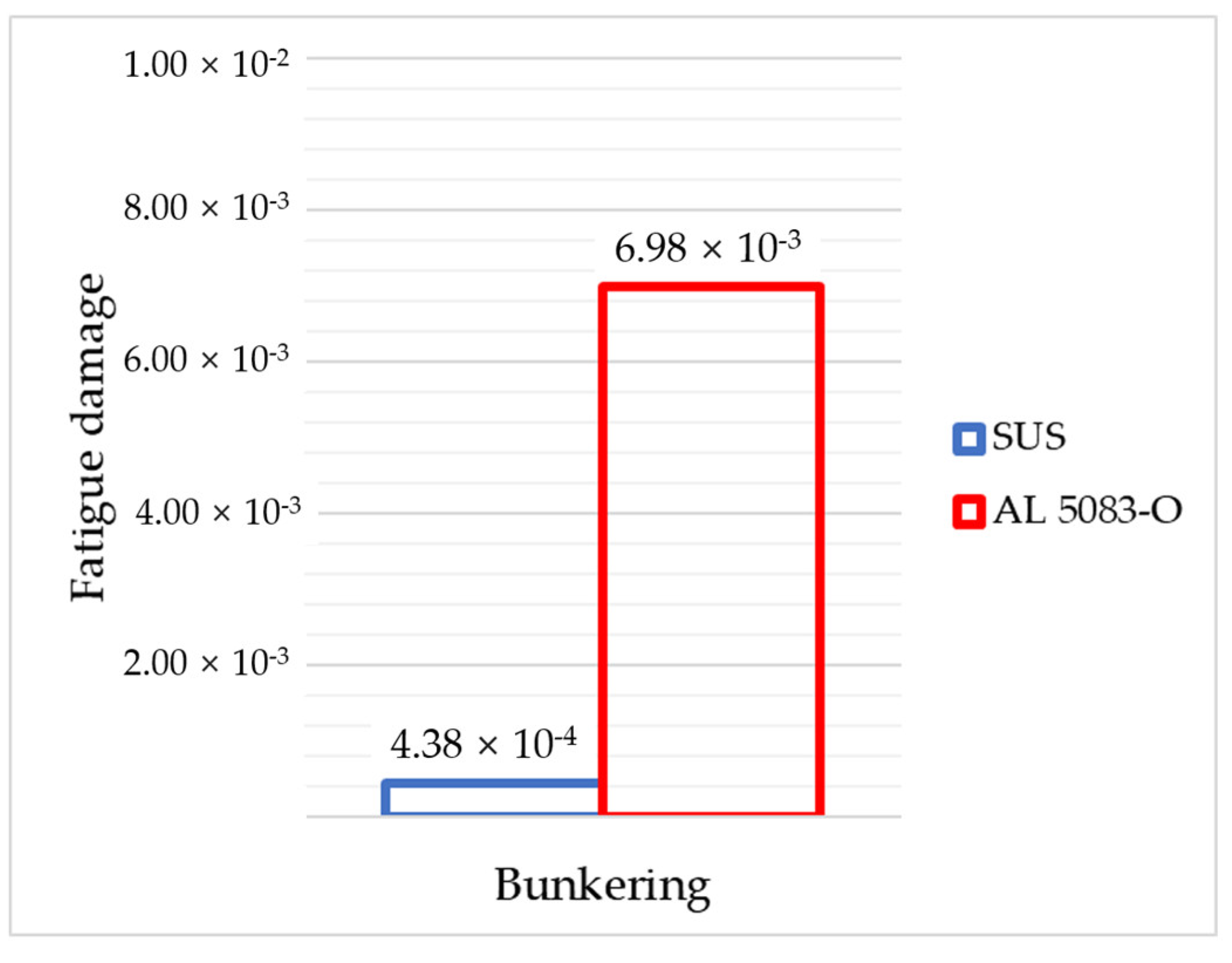
Figure 20.
Comparison of low fatigue damage ratios based on different materials.
Table 1.
Specifications of target vessel with type-C cylindrical tank.
| L (m) | CB | B (m) | x (m) | y (m) | z (m) | V (knot) | K | ρ (kg/m3) |
|---|
| 34 | 0.662 | 10.6 | 12.5 | 0.092 | −0.079 | 12.5 | 5.0 | 500 |
Table 2.
Mechanical and thermal properties of target materials.
| Parameter | Carbon Steel DH36 | SUS304 | SUS304L | AL 5083-O | Bakelite |
|---|
| Poisson’s ratio | 0.30 | 0.29 | 0.29 | 0.33 | 0.29 |
| Elastic modulus (MPa) | 205,800 | 193,000 | 193,000 | 71,000 | 8300 |
| Density (tonne/m3) | 7.85 | 8.00 | 8.00 | 2.66 | 1.28 |
| Yield stress (MPa) | 355 | 205 | 175 | 145 | 55 |
| Ultimate strength (MPa) | 490 | 520 | 480 | 290 | - |
| Thermal conductivity (W/m K) | 59.00 | 9.40 | 9.40 | 117.00 | 0.19 |
| Thermal expansion (mm/K) | 1.2 × 10⁻⁵ | 1.8 × 10⁻⁵ | 1.8 × 10⁻⁵ | 2.23 × 10⁻⁵ | 2.2 × 10⁻⁵ |
| Specific heat (mJ/tonne K) | 4.86 × 10⁸ | 5.00 × 10⁸ | 5.00 × 10⁸ | 9.00 × 10⁸ | 1.67 × 10⁹ |
Table 3.
Load cases for structural analysis.
| Load | Load Cases |
|---|
| Acc. Longi. | Acc. Trans. | Acc.
Vertical | 30° Heeled
Condition | Collision |
|---|
| LNG Temp. (−165 °C) | ○ | ○ | ○ | ○ | ○ |
| Self-weight (gravity 1.0 G) | ○ | ○ | ○ | ○ | ○ |
| Vapor pressure “P0” | ○ | ○ | ○ | ○ | ○ |
| Heeling (30°) | - | - | - | ○ | - |
Internal
liquid
pressure “Pgd” | Liquid static pressure “Ps” | ○ | ○ | ○ | ○ | ○ |
| Dynamic pressure “Pd” | Acc. Longi. | ○ | - | - | - | - |
| Acc. Trans. | - | ○ | - | - | - |
| Acc. Vertical | - | - | ○ | - | - |
| Collision | - | - | - | - | ○ |
Table 4.
Resultant pressure for the load cases.
| Load Cases | Vapor Pressure (MPa) | Internal Pressure (MPa) | Total Pressure for FEA (MPa) |
|---|
| Acc. Longi. | 1.1 | 0.0011 | 1.1011 |
| Acc. Trans. | 0.0050 | 1.1050 |
| Acc. Vertical | 0.0024 | 1.1024 |
| Collision | 0.0047 | 1.1047 |
Table 5.
Design material criteria.
| Material | | | | | | | |
|---|
| Carbon steel (DH36) | 355 | 490 | 163.3 | 163.3 | 245.0 | 490.0 | 319.5 |
| SUS 304 | 205 | 520 | 136.7 | 136.7 | 205.0 | 410.0 | 184.5 |
| SUS 304L | 175 | 480 | 116.7 | 116.7 | 175.0 | 350.0 | 105.0 |
| AL 5083-O | 145 | 290 | 72.5 | 72.5 | 108.8 | 217.5 | 65.3 |
Table 6.
A and B for calculation of reference allowable stress.
| Parameter | Nickel Steels and Carbon–Manganese Steels | Austenitic Steel | Aluminum Alloy |
|---|
| A | 3.0 | 3.5 | 4.0 |
| B | 1.5 | 1.5 | 1.5 |
Table 7.
Summary of structural analysis results.
| Material | Max. Stress (MPa) |
|---|
| SUS304 | SUS304L | AL 5083-O |
|---|
| Load case | Acc. Longi. | 298.5 | 298.5 | 174.8 |
| Acc. Trans. | 323.0 | 323.0 | 194.2 |
| Acc. Vertical | 315.9 | 315.9 | 174.8 |
| 30° Heel | 292.5 | 292.5 | 169.8 |
| Collision | 315.5 | 315.5 | 183.9 |
| Allowable stress (3.0f) | 410 | 350 | 217.5 |
Table 8.
Summary of fatigue analysis results.
| Material | Load Case | Stress Range (MPa) | NLoading | nLoading | Fatigue Damage |
|---|
| SUS304 | High cycle | Acc. Longi. | 3.45 | - | - | 1.54 × 10⁻²⁷ |
| Acc. Trans. | 29.6 | - | - | 5.17× 10⁻⁷ |
| Acc. Vert. | 6.1 | - | - | 1.93× 10⁻¹² |
| Low cycle | Bunkering | 47.8 | 2.29 × 10⁶ | 1000 | 4.38 × 10⁻⁴ |
| AL 5083-O | High cycle | Acc. Longi. | 1.12 | - | - | 1.02 × 10⁻²⁹ |
| Acc. Trans. | 8.62 | - | - | 3.25 × 10⁻¹⁰ |
| Acc. Vert. | 2.24 | - | - | 4.28 × 10⁻²³ |
| Low cycle | Bunkering | 48.2 | 1.43 × 10⁵ | 1000 | 6.98 × 10⁻³ |
| Publisher’s Note: MDPI stays neutral with regard to jurisdictional claims in published maps and institutional affiliations. |
© 2021 by the authors. Licensee MDPI, Basel, Switzerland. This article is an open access article distributed under the terms and conditions of the Creative Commons Attribution (CC BY) license (https://creativecommons.org/licenses/by/4.0/).


