
Influence of Copper Interlayers on the Magnetic Pulse Welding Process between Aluminum and Steel
by
 ,
,
Joerg Bellmann
1,2,* ,
,
Kristina Roder
3,
Martina Zimmermann
2,4,
Eckhard Beyer
1,
Lothar Kroll
3 and
Daisy Nestler
3 1
Institute of Manufacturing Science and Engineering, Department of Mechanical Science and Engineering, Technische Universität Dresden, George-Baehr-Str. 3c, 01062 Dresden, Germany
2
Fraunhofer Institute for Material and Beam Technology IWS, Winterbergstr. 28, 01277 Dresden, Germany
3
Institute of Lightweight Structures, Professorship of Lightweight Structures and Polymer Technology, Department of Mechanical Engineering, Chemnitz University of Technology, Reichenhainer Str. 31/33, 09126 Chemnitz, Germany
4
Institute of Material Science, Professorship of Mechanics of Materials and Failure Analysis, Department of Mechanical Science and Engineering, Technische Universität Dresden, Helmholtzstr. 7, 01069 Dresden, Germany
*
Author to whom correspondence should be addressed.
Metals 2021, 11(6), 868; https://doi.org/10.3390/met11060868
Submission received: 26 April 2021
/
Revised: 19 May 2021
/
Accepted: 21 May 2021
/
Published: 26 May 2021
(This article belongs to the Special Issue High Power Pulsed Processes for Welding and Forming of Metallic Materials)
Abstract
:Magnetic pulse welding (MPW) is a promising joining technology for the large-scale production of dissimilar metallic joints. Although the heat input is comparatively low, the temporary occurrence of high temperatures in the joining gap was found to play an important role during the joint formation. It is possible that the melting or even the boiling temperature of the involved materials will be exceeded, and fusion welding will occur. The purpose of this study is to investigate the influence of target materials with different thermal properties on the joint formation and weld seam characteristic. Therefore, MPW between steel targets and aluminum flyers was performed with and without copper coatings on steel. The lower melting temperature of copper compared to steel had no significant effect on the appearance of the mixed zones in the interface and the amount of molten target material or aluminum, respectively. Nevertheless, the comparison of the higher impact energies showed, that the copper interlayer can lead to a decrease in the weld length or a degradation of the weld quality due to an extended intermetallic phase formation or cracks. This result is important for the parameter adjustment of magnetic pulse welding processes.
1. Introduction
The combination of dissimilar materials like steel, aluminum alloy or magnesium alloy within one component is important to implement lightweight design or increase the load capability. At the same time, suitable joining technologies are required to ensure durable connections between these different metallic material groups. Conventional fusion welding technologies for welding of materials within one material group, e.g., different steels, are often not applicable for dissimilar material combinations due to the huge differences in thermo-physical properties, e.g., the melting temperatures as well as the formation of brittle intermetallic phases. The application of pressure welding technologies offers the reduction of the heat input and, thus, can avoid the formation of critical intermetallic phases. The necessary pressure can be applied by a high-speed impact as it occurs during explosive welding (EXW), vaporizing foil actuator welding (VFAW), laser impact welding (LIW) or magnetic pulse welding (MPW) [1,2]. MPW is based on the electromagnetically driven high-speed forming operation of a workpiece (flyer), followed by the oblique collision with a stationary joining partner (target). It is suitable for the large-scale production of parts with a limited wall thicknesses of a few millimeters [3]. The charging voltage of the capacitors in the pulse generator is one of the key parameters to adjust the energy input [4]. Besides the geometrical setup and the discharging frequency, it determines the magnetic pressure distribution, the forming behavior and, finally, the collision conditions. So-called welding windows relate the impact conditions, in particular the collision point velocity and collision angle, to the welding result. Typically, the material-specific welding windows result from welding experiments carried out between sheets, for example, by EXW [5], gas gun experiments [6], MPW [7] or in pure mechanical test rigs [8]. The most common theory of the joint formation is based on a solid-state approach, where the mechanical properties such as strength and Young’s modulus determine the pressure at the collision point and the formation of the essential “jet” [5]. The jet is generated by the severe plastic deformation beyond a certain impact velocity and is often described as a metal stream that consists of material of both the target and flyer part, depending on their mechanical properties. Furthermore, a wave formation often occurs at the interface [9]. Although this is not a necessary welding criterion [10] it can be attributed to the large plastic deformations in the joining zone, too. The plastic deformation during MPW can be visualized, for example, by anodized surfaces where the oxides are used as tracer particles [11,12,13].
The latest scientific results revealed also the influence and the importance of the heat input due to the hot cloud of particles (CoP) in front of the collision point [13]. The CoP has a lower density compared to the jet described above. It is formed at the initial point of impact, cumulates during the propagating collision point and consists of detached particles from both joining partners surfaces. During the ejection of this cloud out of the closing joining gap it is compressed and suddenly heated up. The collision angle determines the degree of compression and, thus, the resulting temperature in the joining gap [14]. During MPW of sheets, a temperature of 5600 K was measured. It results in the melting of the joining surfaces within a depth of up to a few micrometer before they come into contact [15]. The huge temperature gradient leads to a rapid heat flow to the base materials and comparable narrow heat affected zones. Cooling rates of up to 107 K/s “freeze” the molten material mixture, lead to metastable phase formation [16], nanocrystalline structures [17] and suppress diffusion effects at the interface. The content of the mixed interface depends on the melting temperatures of the involved materials and the process parameters. Compared to the solid-state based approach, the fusion-based joining theory requires a lower joining pressure, impact velocity and, thus, reduces the loading on the tool coils. Small collision angles [14] or the application of reactive interlayers [18] can support this mechanism since both strategies lead to higher temperatures in the joining zone.
Until now, a more profound investigation of the influence of the materials’ thermal properties was difficult, because a material replacement would result in a change of the mechanical properties, that also determine the elastic force and spring back effects, having their own impact on the formation of the joining interface. In order to separate both effects, the flyer and target materials aluminum and steel, respectively, are retained in the study presented while a thin copper interlayer on the target surface is applied in some experiments. With this strategy, the mechanical properties of the joining partners should be unaffected and the influence of the thermal properties can be studied separately. This allows a deepened understanding of the fusion-based joining mechanism during MPW and identification of the most relevant material properties.
In Section 2, the experimental strategy is described in detail, including a description of the setup, the materials that are used in this study as well as the methods for sample analysis. The obtained results by optical and scanning electron microscopy are presented in Section 3, followed by the discussion and conclusion section.
2. Materials and Methods
2.1. Overview and Nomenclature
The aim of this study is to separate the influences of the thermal and mechanical properties of the joining partners during MPW. Therefore, two welding setups are utilized:
- Reference welding setup consisting of an aluminum (Al) flyer tube and a steel (St) cylinder as target, in relevance of Al-St lightweight constructions in the transportation sector.
- Reference welding setup supplemented by a copper (Cu) interlayer on the steel target, hence, considering the relevance of Al-Cu joints for electromobility.
This experimental strategy enables one to study the influence of the thermal properties of the target surface materials steel and copper independently from the differences in their mechanical properties. Because the copper interlayer has a thickness of only a few micrometers, its impact on the stiffness and deformation behavior of the target substrate is neglectable in this study. Copper was chosen as an interlayer material in order to avoid a pronounced exothermic reaction as occurs in the Al-Ni system [18]. Furthermore, the flyer kinetic is assumed to be unaffected by the interlayer. Thus, the collision conditions as well as the pressure and temperature distributions in the joining zones are comparable. Welding experiments are performed at two different energy levels where the kinetic collision conditions have been analyzed previously [18]. To consider the unsteady course of the pressure and temperature along the collision zone, selected locations of the weld interface are analyzed. The symbols for the description of their characteristic and for the experimental setup used in this paper are summarized in Table 1.
2.2. MPW Process and Material Properties
Magnetic pulse welding experiments between aluminum flyer tubes and steel cylinders were conducted using the setup shown in Figure 1, including a single turn working coil and the pulse generator MPW 50/25 by Bmax (Toulouse, France) with its characteristic values summarized in Table 2. The chemical compositions for the materials of the joining partners are listed in Table 3 and were transcribed from the data sheets of the manufacturer. The chemical composition of the copper coating was determined by energy dispersive X-ray spectroscopy–EDS (QUANTAX EDS by Bruker Corporation, Billerica, MA, USA). The main element is copper. Traces of sulfur are also present. Every part was cleaned in ethanol before the joining experiment to remove contaminations from the surfaces. The geometrical conditions were kept constant for each trial and two values were changed independently:
- The charging energy of the pulse generator was set to either 5.8 kJ or 8.0 kJ. This led to a maximum tool coil current of approx. 426 kA or 485 kA, respectively, measured with a Rogowski current probe CWT 3000 B from Power Electronic Measurements Ltd. (Nottingham, UK).
- The surfaces of some steel targets were coated with a 5 µm copper layer in a cyanide based galvanic process.
Following the aim of this study, the most relevant thermal properties of the flyer material aluminum, the target material steel and the coating material copper are compared in Table 4.
2.3. Sample Analysis
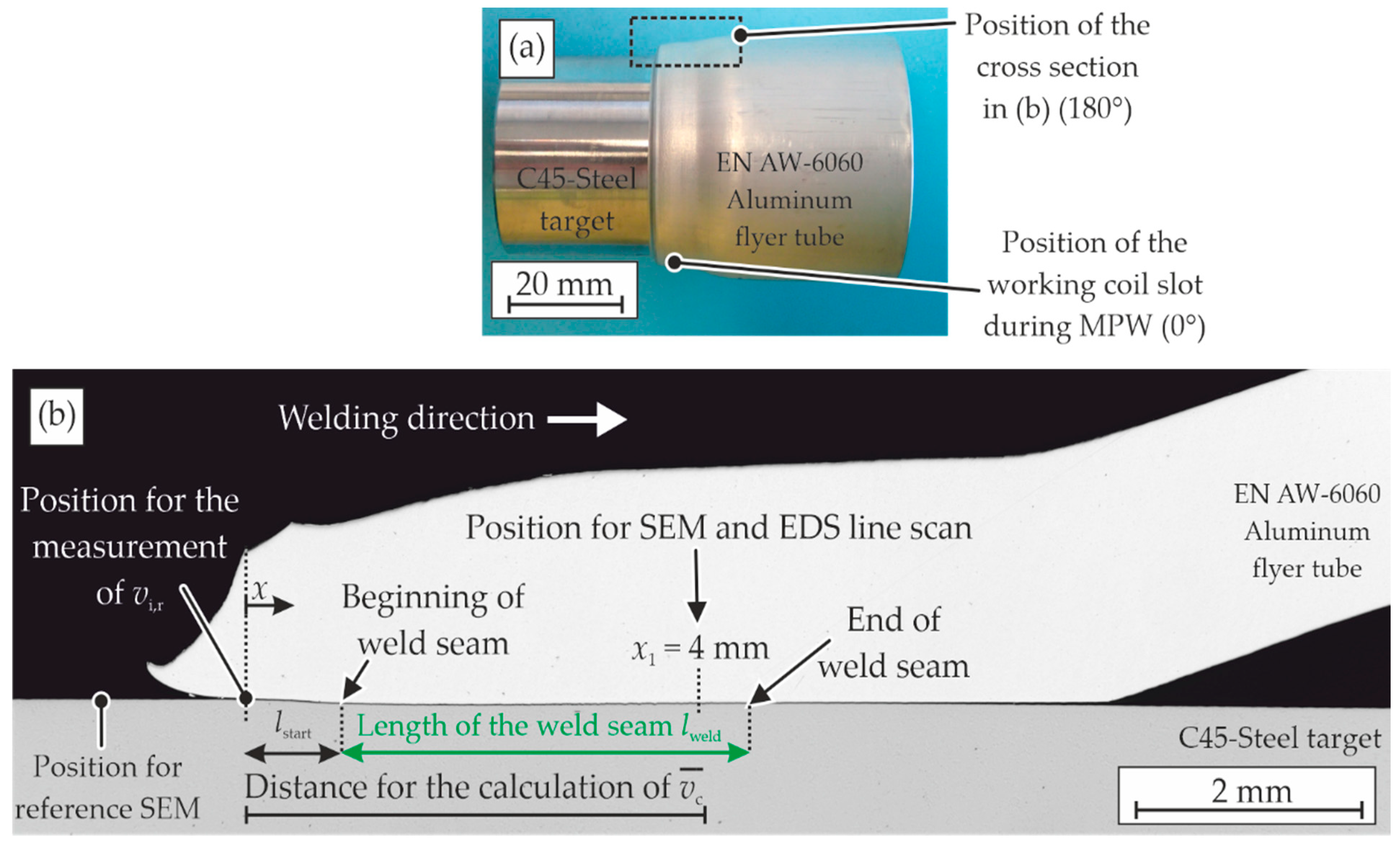
Cross sections were prepared after MPW from each sample at the 180° position, see Figure 2a. The samples were grinded and final polished with a suspension that contained 0.05 µm Al2O3 or SiO2 particles. Optical microscopy (GX-51 by Olympus, Tokyo, Japan) was applied to identify the start and length of the weld seam lstart and lweld, respectively, as depicted in Figure 2b. Scanning electron microscopy–SEM (JSM-6610LV by Jeol, Tokyo, Japan and Leo1455VP by Zeiss, Oberkochen, Germany) was performed at selected positions and energy dispersive X-ray spectroscopy–EDS (GENESIS, EDAX by AMETEK, Inc., Berwyn, PA, USA) at the indicated position x1.
3. Results
3.1. Optical Microscopy
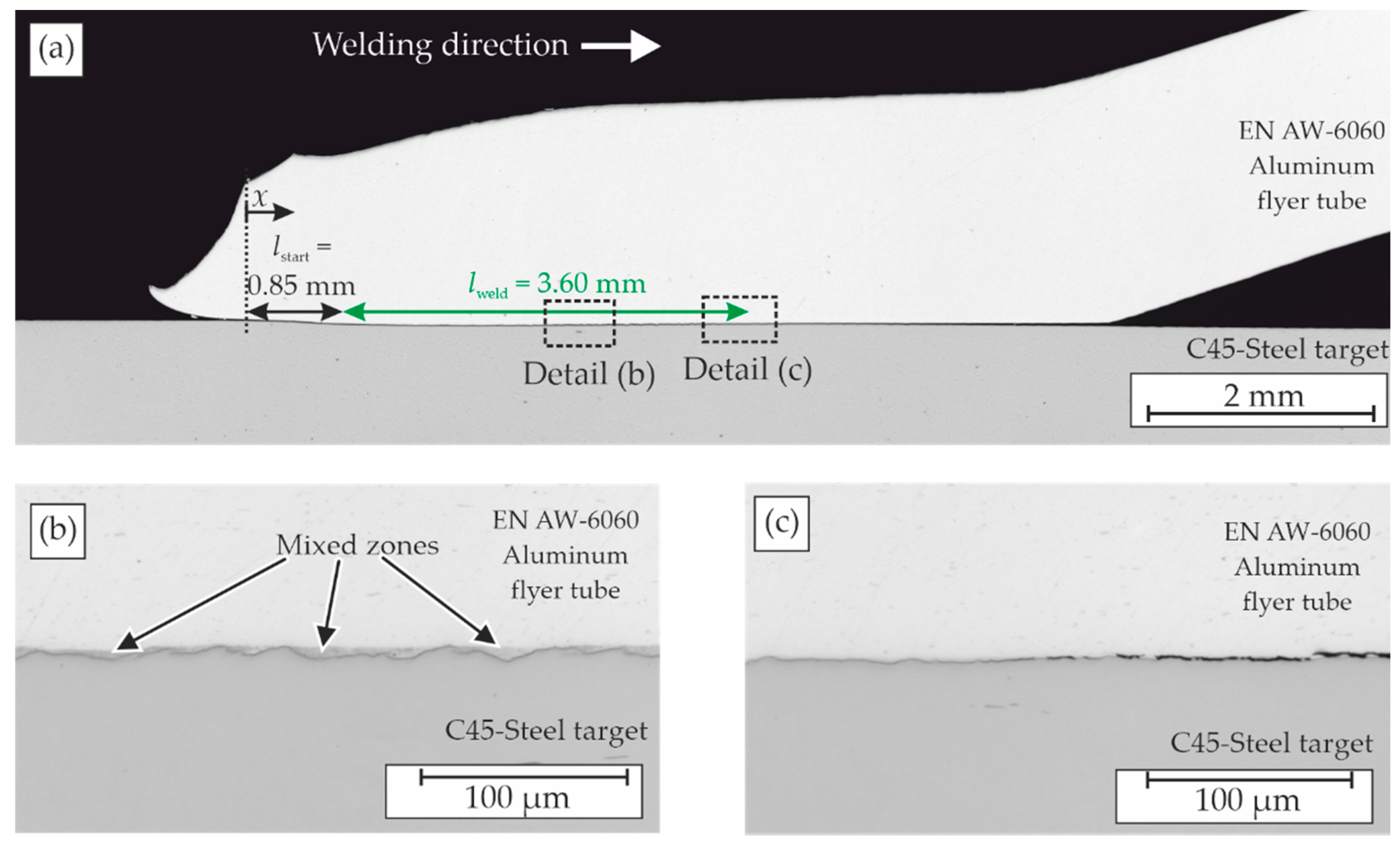
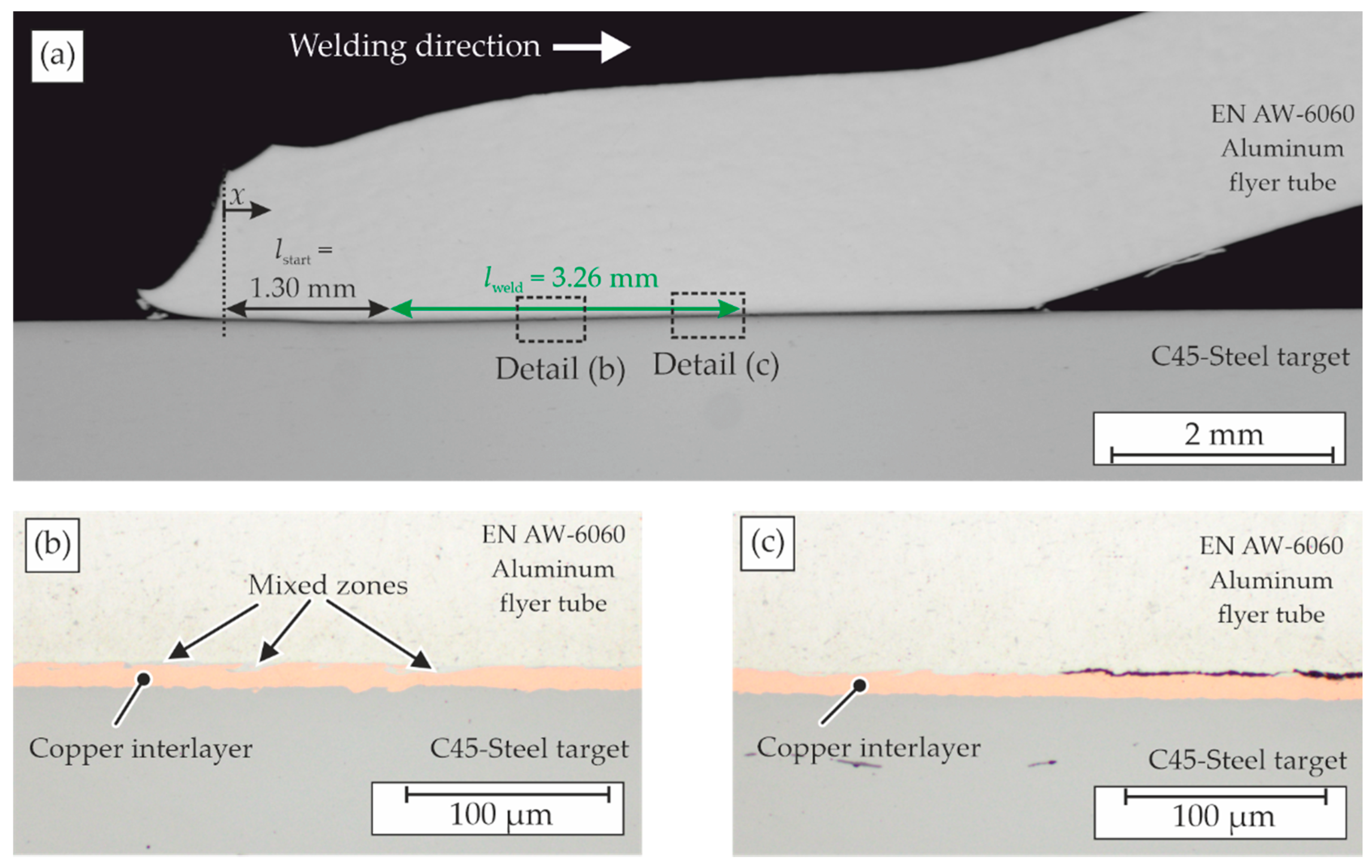
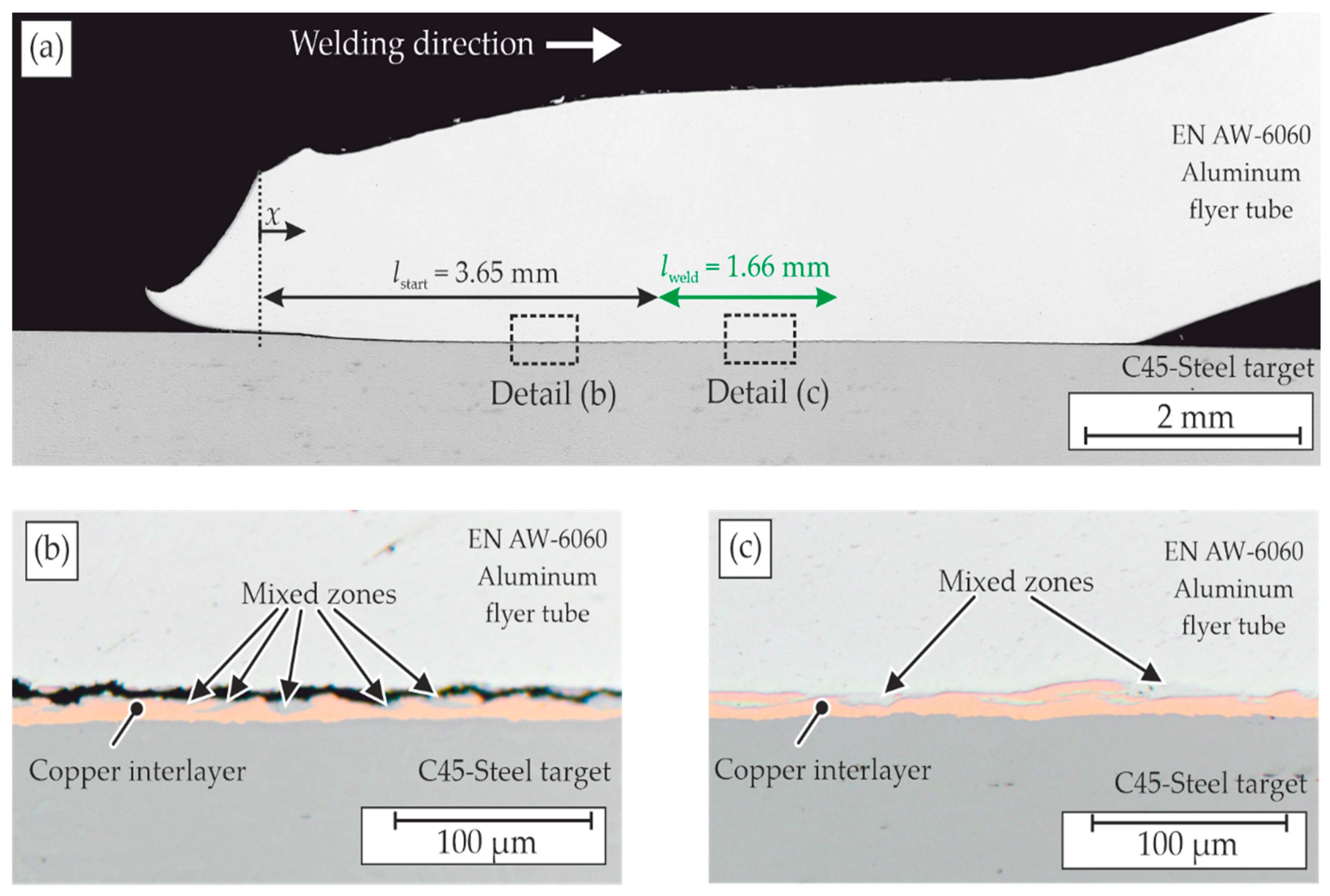
The polished cross sections were analyzed by optical microscopy to determine the beginning and length of the weld seam; see Figure 3, Figure 4, Figure 5 and Figure 6 and summary in Table 5. On the lower energy level, the influence of the copper interlayer on the weld formation is small. Increasing the charging energy to 8 kJ leads to a longer weld seam at the sample without the interlayer. Contrastingly, the sample with the copper interlayer exhibits a delay in the weld formation as well as a shorter weld seam, see Figure 4a and Figure 6a. As depicted in Figure 6b, there is an almost continuous band of mixed zones on top of the copper interlayer and a separated aluminum flyer. The excessive heat input at the beginning of the collision zone, followed by a critical formation of intermetallic phases and, therefore, a susceptibility towards process-related localized shrinkage crack formation are assumed to be the main reasons for this finding. Figure 3b and Figure 6c show details from the weld seams where the energy input was well metered, leading to discontinuous mixed zones that alternate with direct contact zones between the aluminum flyer and the copper interlayer. Thus, there is a significant influence of the copper coating, especially at higher impact velocities and collision front velocities, respectively.
3.2. Scanning Electron Microscopy and Energy Dispersive X-ray Spectroscopy
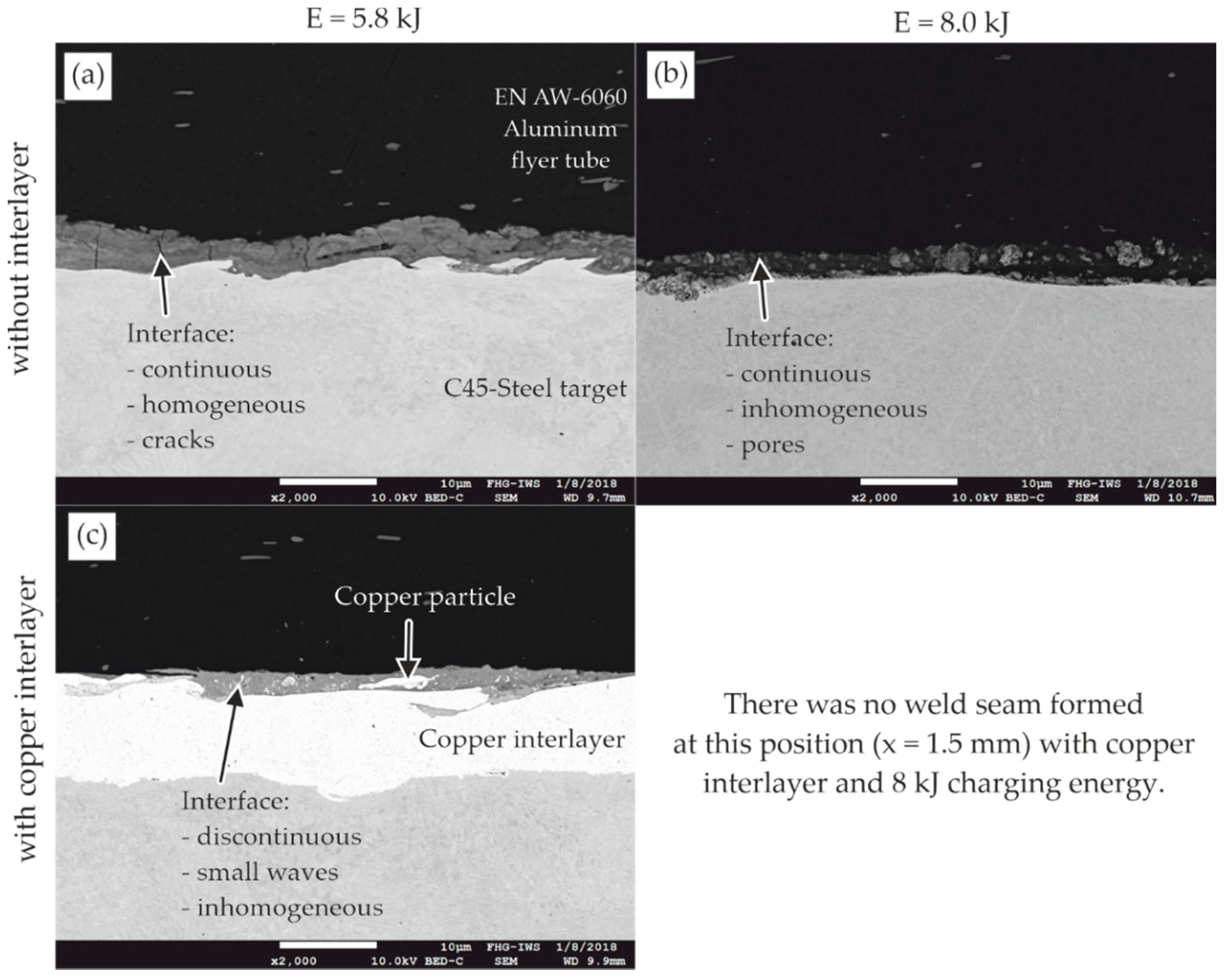
Following the aim of this study to investigate the influence of the thermal properties of the joining partners, a detailed comparison of the morphologies of the interfaces was performed via scanning electron microscopy (SEM). Because the interface characteristic changes along the weld formation, selected locations at the beginning (x = 1.5 mm, Figure 7a–d) and at the end of the weld seam (x = ~4 mm, Figure 8a–d) are compared. Mixed zones occur in every configuration and at both locations, while their characteristic differ significantly. The process related cooling rates in the order of 107 K/s “freeze” inhomogeneous structures such as streaks or small particles of the involved materials immediately [13]. The duration, while the materials occur in a liquid or gaseous state, is often too short for complete chemical reactions and a homogeneous distribution of the reaction products. A detailed comparison of the SEM-pictures reveals that:
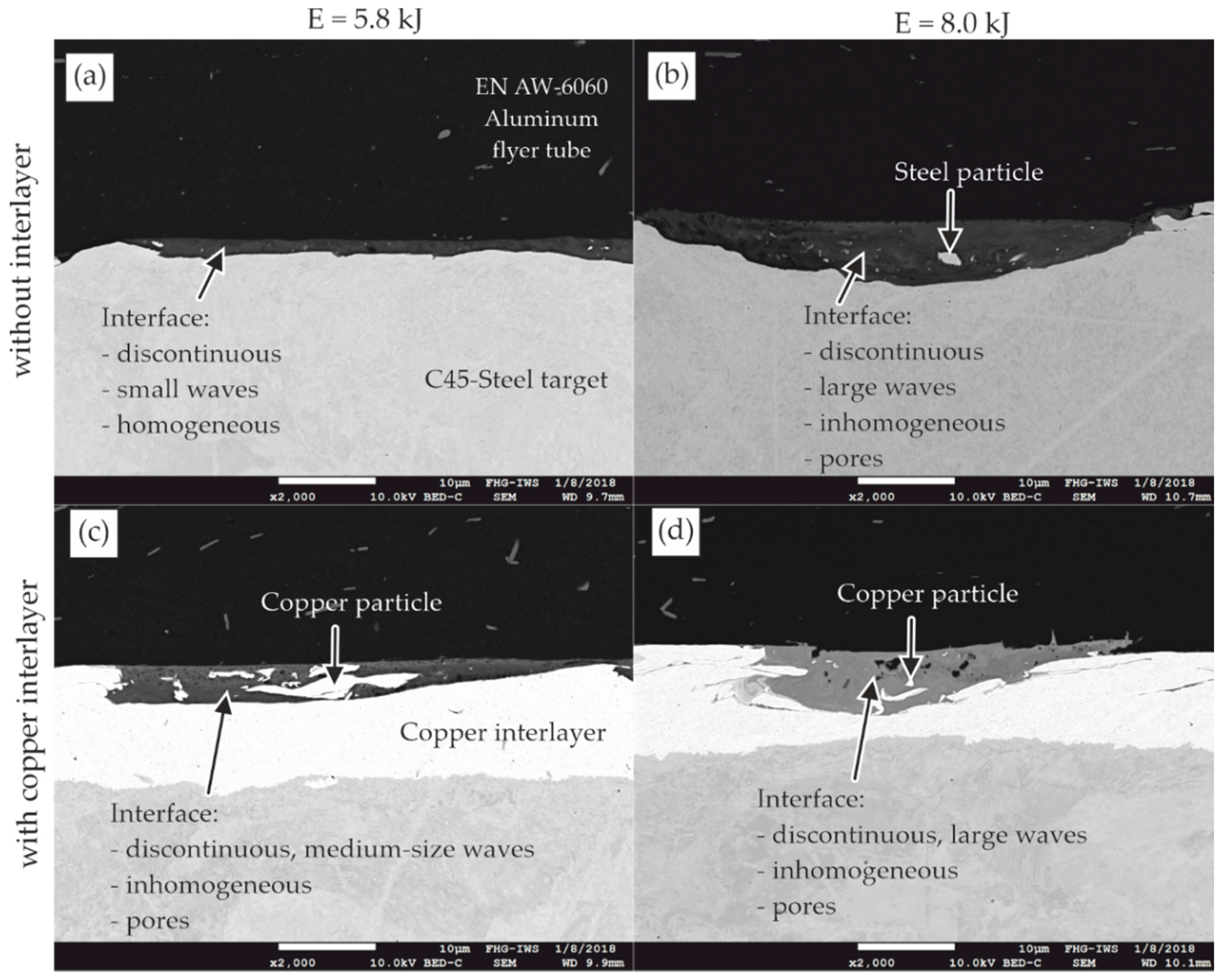
- The wave height as a measure for the plastic deformation of the copper interlayer, as well as its interaction with the aluminum flyer, are increased compared to the direct magnetic pulse welded sample on the steel surface. This effect occurs already at the beginning of the weld seam.
- The size of the waves and the number of pores increase from the beginning to the end of the weld seams, especially on the higher energy level of 8 kJ.
- Increasing the charging energy from 5.8 to 8.0 kJ leads to higher waves, especially at the end of the weld seams. The volume of the mixed zone increases, too. An unfavorable distribution of these zones, meaning an almost continuous band of intermetallic phases as mentioned previously in Figure 6b, can lead to excessive cracking and separation after MPW, while a wavy characteristic with a discontinuous intermetallic phase occurrence is beneficial for the joint quality.
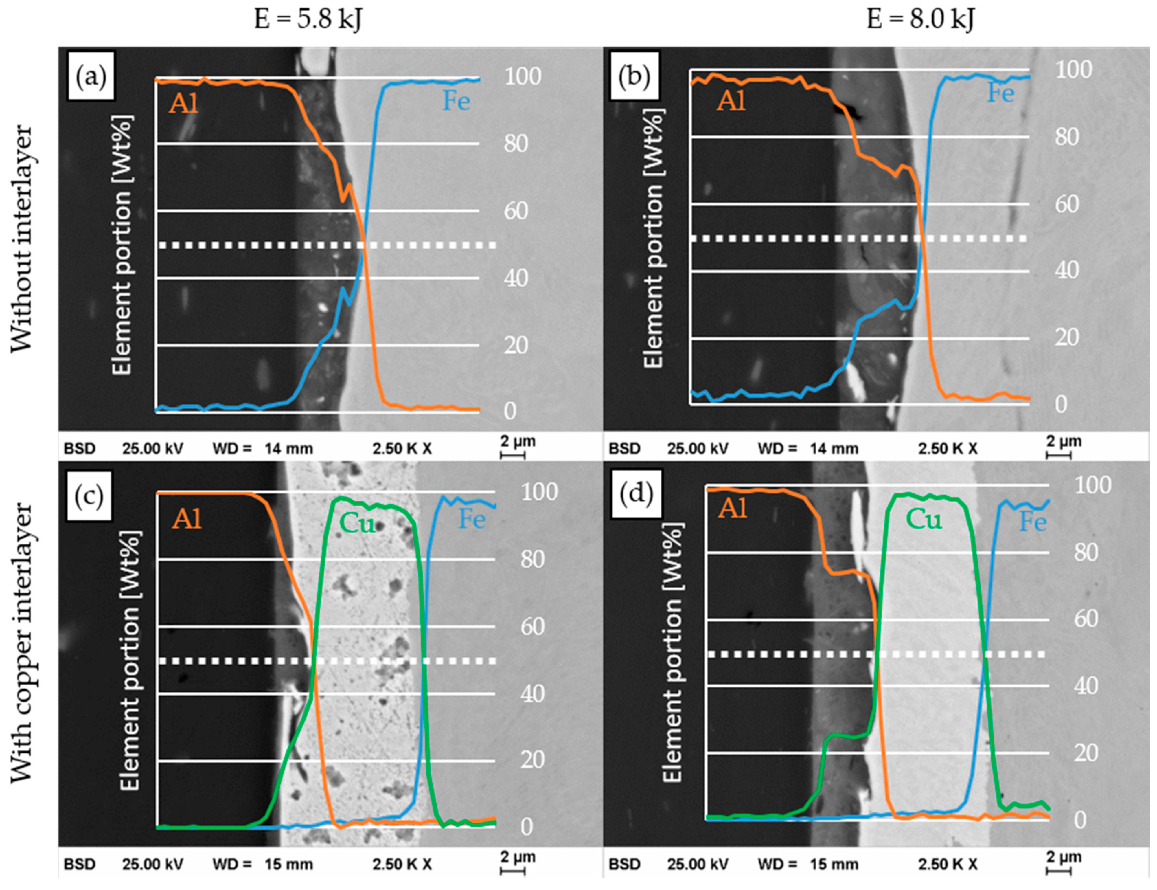
Besides the finding of an increased wave formation at the plastically deformed copper interlayer, its effect on the metallurgical composition of the mixed zone was studied by energy dispersive X-ray spectroscopy (EDS). The line scans perpendicular to the weld interface at the end of the weld seam (x1 = 4 mm) are plotted in Figure 9. At the lower energy level, the mixed zones between aluminum and steel (a) and copper (c), respectively, are very thin. Thus, a roughly linear transition between the two elements is measured and probably reflects the activation volume during EDS measurements. Because the thickness of this zone increases with the higher energy input of 8 kJ, a plateau in the element distribution can be detected. The ratio is approximately 70 wt% aluminum and 30 wt% iron (b) and copper (d), respectively. Further insights into the formation of the intermetallic layers would require an analysis on a much higher resolution level such as by means of TEM analysis (e.g., [24]). However, since this study was focused on the influence of the copper interlayer on the overall joint formation, no further nanoscale analyses were carried out.
4. Discussion
This study highlights the importance of the heat input on the joint formation and weld seam characteristic during magnetic pulse welding. Because the joining pressure decreases along the collision front propagation, the increasing mixing zones in the weld seam cannot be explained by the solid-state welding approach. Instead, it could be verified that the heat transfer from the hot cloud of particles in the joining gap to the surfaces must have been responsible for this finding and the occurring fusion-based welding mechanism. It is known from previous studies that a minimum impact velocity must be reached to establish the cloud of particles (CoP) in the joining gap [25] and that the impact angle should be small to ensure a sufficient compression and heating of the CoP and joining surfaces, respectively [15].
Aluminum has a lower melting temperature compared to steel and copper. Thus, the mixed zones of the welding interface contain approx. 70 wt% of this material. There was no effect of the copper interlayer detectable at the investigated welding position compared to the direct joined steel–aluminum sample. Probably, the difference between the melting temperatures of steel and copper is too small (453 K) compared to the temperatures in the joining gap of up to 5600 K [15]. The plastic deformation of the copper interlayer and its interaction with the aluminum flyer are increased compared to the direct magnetic pulse welded sample on the steel surface. Since this effect occurs already at the beginning of the weld seam, where the heat input is comparatively low due to the cloud of particles, the lower hardness of copper seems reasonable.
At the higher energy level, the copper coating on the steel surface has affected the position of the weld seam. The heat input close to the initial point of impact leads to the formation of an almost continuous layer of intermetallic phases but also resulted in undesirable separation effects. In case of the direct joining of aluminum to steel, these separation effects do not occur. The size of the waves and the number of pores increase from the beginning to the end of the weld seams, especially on the higher energy level of 8 kJ. Because the radial impact velocity decreases along the weld front propagation, it is unlikely to explain this finding by the kinetic energy input. The only possible explanations are the increased collision angle or the heat input by the accumulated cloud of particles. The fact that the number of pores grows alike supports the theory of the heat input by the cloud of particles, which can lead to melting and even vaporization. The increased collision angle is unlikely to explain the detected pores, because it would facilitate the escape of the remaining air and gaseous material out of the joining gap.
If a higher kinetic energy input is applied to increase the weld seam length, the thermal energy input must be controlled carefully. If it is too high, large mixing zones can form with higher risk for shrinkage cracks, formation of brittle intermetallic phases or separation effects before the complete solidification of the molten material. The upper boundary of the energy input depends on the material combination and can be controlled by the collision conditions, for example, the collision angle.
5. Conclusions
The major insights that have been worked out regarding the magnetic pulse welding process of aluminum to steel with and without a copper interlayer based on the fusion welding mechanism in the study presented can be summarized as follows:
- The heat transfer from the hot cloud of particles to the surfaces of the joining partners results in local melting and formation of mixed zones.
- These zones contain about 70 wt% of the flyer material aluminum with the lower melting temperature and 30 wt% of the parent material steel or the interlayer material copper with higher melting temperatures, respectively.
- The wave formation in the joining zone is increased by the copper interlayer compared to the direct welding of aluminum to steel, probably because of the differences in hardness.
- The weld formation between the aluminum flyer and the copper interlayer is more sensitive to the energy input during the high-speed impact compared to the direct welding of aluminum to steel. If the impact velocity is too high, an almost continuous layer of intermetallic phases forms and results in undesirable separation effects.
- It is important to adjust the kinetic energy input at the lower process boundary in order to minimize the formation of a continuous layer of intermetallic phases, especially at the material combination aluminum–copper. Setting up a suitable (small) collision angle is more likely than just increasing the charging energy to achieve a weld.
Finally, it should be noted once again, that the parameter adjustment for magnetic pulse welding processes is a complex task with many influencing factors. The parameters not only depend on the local kinetic collision conditions or the material properties, but also on the cumulated cloud of particles and its heat input towards the surfaces. The investigation of the localized and time-resolved heat input and cooling behavior will be an important part of future studies. These criteria have not been taken into account in the traditional welding windows, but are key parameters in order to homogenize the properties of magnetic pulse weld seams.
Author Contributions
Conceptualization, J.B. and K.R.; Data curation, J.B. and K.R.; Funding acquisition, M.Z., E.B., L.K. and D.N.; Investigation, J.B. and K.R.; Methodology, J.B. and K.R.; Project administration, M.Z., E.B., L.K. and D.N.; Resources, M.Z., E.B., L.K. and D.N.; Supervision, M.Z., E.B., L.K. and D.N.; Validation, M.Z., L.K. and D.N.; Visualization, J.B.; Writing—original draft, J.B.; Writing—review & editing, K.R., M.Z., E.B., L.K. and D.N. All authors have read and agreed to the published version of the manuscript.
Funding
This research was funded by the Deutsche Forschungsgemeinschaft (DFG, German Research Foundation), grant number BE 1875/30-3. This work includes results of subproject A1 of the priority program 1640 (“joining by plastic deformation”). Open Access Funding by the Publication Fund of the TU Dresden.
Data Availability Statement
The data presented in this study are available on request from the corresponding author.
Acknowledgments
We would like to acknowledge the effort for the sample preparation and SEM analysis at Fraunhofer IWS Dresden.
Conflicts of Interest
The authors declare no conflict of interest. The funders had no role in the design of the study; in the collection, analyses, or interpretation of data; in the writing of the manuscript, or in the decision to publish the results.
References
- Wang, H.; Wang, Y. High-Velocity Impact Welding Process: A Review. Metals 2019, 9, 144. [Google Scholar]
- Sadeh, S.; Gleason, G.H.; Hatamleh, M.I.; Sunny, S.F.; Yu, H.; Malik, A.S.; Qian, D. Simulation and experimental comparison of laser impact welding with a plasma pressure model. Metals 2019, 9, 1196. [Google Scholar] [CrossRef] [Green Version]
- Zhang, Y.; Babu, S.S.; Prothe, C.; Blakely, M.; Kwasegroch, J.; LaHa, M.; Daehn, G.S. Application of high velocity impact welding at varied different length scales. J. Mater. Process. Technol. 2010, 211, 944–952. [Google Scholar] [CrossRef]
- Raoelison, R.N.; Buiron, N.; Rachik, M.; Haye, D.; Franz, G.; Habak, M. Study of the elaboration of a practical weldability window in magnetic pulse welding. J. Mater. Process. Technol. 2013, 213, 1348–1354. [Google Scholar] [CrossRef]
- Carpenter, S.H.; Wittmann, R.H. Explosive welding. Ann. Rev. Mater. Sci. 1975, 5, 177–199. [Google Scholar] [CrossRef]
- Botros, K.K.; Groves, T.K. Fundamental impact-welding parameters—an experimental investigation using a 76-mm powder cannon. J. Appl. Phys. 1980, 51, 3706–3714. [Google Scholar] [CrossRef]
- Cuq-Lelandais, J.P.; Ferreira, S.; Avrillaud, G.; Mazars, G.; Rauffet, B. Magnetic pulse welding: Welding windows and high velocity impact simulations. In Proceedings of the 6th International Conference on High Speed Forming, Daejeon, Korea, 26–29 May 2014; pp. 199–206. [Google Scholar]
- Groche, P.; Becker, M.; Pabst, C. Process window acquisition for impact welding processes. Mater. Des. 2017, 118, 286–293. [Google Scholar] [CrossRef]
- Ben-Artzy, A.; Stern, A.; Frage, N.; Shribman, V.; Sadot, O. Wave formation mechanism in magnetic pulse welding. Int. J. Impact Eng. 2010, 397–404. [Google Scholar] [CrossRef]
- Göbel, G.; Kaspar, J.; Herrmannsdörfer, T.; Brenner, B.; Beyer, E. Insights into intermetallic phases on pulse welded dissimilar metal joints. In Proceedings of the 4th International Conference on High Speed Forming, Columbus, OH, USA, 9–10 March 2010; pp. 127–136. [Google Scholar]
- Lueg-Althoff, J.; Bellmann, J.; Gies, S.; Schulze, S.; Tekkaya, A.E.; Beyer, E. Influence of the flyer kinetics on magnetic pulse welding of tubes. J. Mater. Process. Technol. 2018, 189–203. [Google Scholar] [CrossRef]
- Bellmann, J.; Lueg-Althoff, J.; Göbel, G.; Gies, S.; Beyer, E.; Tekkaya, A.E. Effects of surface coatings on the joint formation during magnetic pulse welding in tube-to-cylinder configuration. In Proceedings of the 7th International Conference on High Speed Forming, Dortmund, Germany, 27–28 April 2016; pp. 279–288. [Google Scholar]
- Bellmann, J.; Lueg-Althoff, J.; Schulze, S.; Hahn, M.; Gies, S.; Beyer, E.; Tekkaya, A.E. Thermal effects in dissimilar magnetic pulse welding. Metals 2019, 9, 348. [Google Scholar] [CrossRef] [Green Version]
- Bellmann, J.; Ueberschär, F.; Lueg-Althoff, J.; Schulze, S.; Hahn, M.; Beyer, E.; Tekkaya, A.E. Effect of the forming behavior on the impact flash during magnetic pulse welding of tubes. In Proceedings of the 13th International Conference on Numerical Methods in Industrial Forming Processes, Portsmouth, NH, USA, 23–27 June 2019; pp. 651–654. [Google Scholar]
- Bellmann, J.; Lueg-Althoff, J.; Niessen, B.; Böhme, M.; Schumacher, E.; Beyer, E.; Leyens, C.; Tekkaya, A.E.; Groche, P.; Wagner, M.F.X.; et al. Particle ejection by jetting and related effects in impact welding processes. Metals 2020, 1108. [Google Scholar] [CrossRef]
- Bataev, I.A.; Lazurenko, D.V.; Tanaka, S.; Hokamoto, K.; Bataev, A.A.; Guo, Y.; Jorge, A.M. High cooling rates and metastable phases at the interfaces of explosively welded materials. Acta Mater. 2017, 135, 277–289. [Google Scholar] [CrossRef]
- Böhme, M.; Sharafiev, S.; Schumacher, E.; Böhm, S.; Wagner, M.F.X. On the microstructure and the origin of intermetallic phase seams in magnetic pulse welding of aluminum and steel. Materialwiss. Werkstofftech. 2019, 50, 958–964. [Google Scholar] [CrossRef]
- Bellmann, J.; Lueg-Althoff, J.; Schulze, S.; Gies, S.; Beyer, E.; Tekkaya, A.E. Effects of reactive interlayers in magnetic pulse welding. In Proceedings of the 8th International Conference on High Speed Forming, Columbus, OH, USA, 13–16 May 2018. [Google Scholar]
- Seeberger. Datasheet AlMgSi (EN AW-6060). Available online: http://www.seeberger.net/_assets/pdf/werkstoffe/aluminium/de/AlMgSi.pdf (accessed on 18 February 2020).
- Günther; Schramm. Datasheet C45 (1.0503). Available online: https://www.gs-stahl.de/images/C45.pdf (accessed on 18 February 2020).
- Bikar-Metalle GmbH. EN AW-6060. Available online: https://www.bikar.com/fileadmin/download/6060-komplett.pdf (accessed on 21 February 2019).
- Fischer, U. Tabellenbuch Metall; 44., Neu Bearbeitete Aufl., 6. Druck; Europa Lehrmittel: Haan-Gruiten, Germany, 2008; ISBN 978-3808517246. [Google Scholar]
- Deutsche Edelstahlwerke. Unlegierter Vergütungsstahl 1.1191/1.1201: C45E/C45R. Available online: https://www.dew-stahl.com/fileadmin/files/dew-stahl.com/documents/Publikationen/Werkstoffdatenblaetter/Baustahl/1.1191_1.1201_de.pdf (accessed on 21 February 2019).
- Kaspar, J.; Zimmermann, M.; Ostwaldt, A.; Goebel, G.; Standfuß, J.; Brenner, B. Challenges in joining aluminium with copper for applications in electro mobility. Mater. Sci. Forum 2014, 783–786, 1747–1752. [Google Scholar] [CrossRef]
- Bellmann, J.; Lueg-Althoff, J.; Schulze, S.; Gies, S.; Beyer, E.; Tekkaya, A.E. Parameter identification for magnetic pulse welding applications. Key Eng. Mater. 2018, 767, 431–438. [Google Scholar] [CrossRef]
Figure 1.
(a) Schematic of the MPW setup and (b) velocity components at the collision point C.

Figure 2.
(a) Sample after MPW; (b) exemplary cross section with indicated position of the weld seam, SEM and EDS line scans.
Figure 2.
(a) Sample after MPW; (b) exemplary cross section with indicated position of the weld seam, SEM and EDS line scans.

Figure 3.
Cross sections of the MPW sample with E = 5.8 kJ and without copper interlayer: (a) overview; (b) welded zone; and (c) end of the welded zone.
Figure 3.
Cross sections of the MPW sample with E = 5.8 kJ and without copper interlayer: (a) overview; (b) welded zone; and (c) end of the welded zone.

Figure 4.
Cross sections of the MPW sample with E = 5.8 kJ and copper interlayer: (a) overview; (b) welded zone; and (c) end of the welded zone.
Figure 4.
Cross sections of the MPW sample with E = 5.8 kJ and copper interlayer: (a) overview; (b) welded zone; and (c) end of the welded zone.

Figure 5.
Cross sections of the MPW sample with E = 8.0 kJ and without copper interlayer: (a) overview; (b) welded zone; and (c) end of the welded zone.
Figure 5.
Cross sections of the MPW sample with E = 8.0 kJ and without copper interlayer: (a) overview; (b) welded zone; and (c) end of the welded zone.

Figure 6.
Cross sections of the MPW sample with E = 8 kJ and copper interlayer: (a) overview; (b) separated zone; and (c) welded zone.
Figure 6.
Cross sections of the MPW sample with E = 8 kJ and copper interlayer: (a) overview; (b) separated zone; and (c) welded zone.

Figure 7.
SEM micrographs of the weld seam start at x = 1.5 mm: (a,b) without and (c) with copper interlayer, magnetic pulse welded at two different energy levels.
Figure 7.
SEM micrographs of the weld seam start at x = 1.5 mm: (a,b) without and (c) with copper interlayer, magnetic pulse welded at two different energy levels.

Figure 8.
SEM micrographs close to the weld seam end at x = ~4 mm: (a,b) without and (c,d) with copper interlayer, magnetic pulse welded at two different energy levels.
Figure 8.
SEM micrographs close to the weld seam end at x = ~4 mm: (a,b) without and (c,d) with copper interlayer, magnetic pulse welded at two different energy levels.

Figure 9.
Comparison of EDS line scans perpendicular to the weld interface at the dotted lines at x1 = 4 mm from samples (a,b) without and (c,d) with copper interlayer magnetic pulse welded at two different energy levels.
Figure 9.
Comparison of EDS line scans perpendicular to the weld interface at the dotted lines at x1 = 4 mm from samples (a,b) without and (c,d) with copper interlayer magnetic pulse welded at two different energy levels.


Table 1.
Nomenclature for experimental setup and sample analysis.
| Symbol | Parameter |
|---|---|
| E | Charging energy |
| g | Initial joining gap |
| I | Discharge current |
| Imax | Maximum discharge current |
| Li | Inner inductance of the pulse generator |
| lw | Working length (axial overlap between the workpiece and the tool coil) |
| lstart | Distance between initial flyer impact and beginning of the weld seam |
| lweld | Length of the weld seam |
| pm | Magnetic pressure |
| Ra | Arithmetical mean roughness index |
| Ri | Inner resistance of the pulse generator |
| s | Thickness of the flyer |
| S | High voltage switch |
| t | Time |
| tf,start | Flash starting time |
| vi,r | Radial impact velocity |
| vc | Axial collision velocity |
| β | Collision angle |
Table 2.
Characteristics of the RLC-circuits and the deployed pulse generator.
| Setup | Unit | Bmax MPW 50/25 |
|---|---|---|
| Capacitance | µF | 160 |
| Inductance 1 | nH | 372 |
| Maximum charging energy | kJ | 32 |
| Maximum charging voltage | kV | 20 |
| Applied charging energy–E | kJ | 5.8/8.0 |
| Discharge frequency 1–fdischarge | kHz | ~21 |
| Damping coefficient γ 1 | 1/s | 16,500 |
1 for the complete RLC-circuit with working coil, field shaper and workpieces.
| Flyer Part EN AW-6060 (Pressed Tube, T66), Quasi-Static Yield Strength > 160 MPa (Ra < 1 µm) | Parent Part C45 (1.0503), Normalized, Quasi-Static Yield Strength Approx. 490 MPa, Surface Polished (Ra = 1 µm) | ||
|---|---|---|---|
| Element | Element Portion [Wt%] | Element | Element Portion [Wt%] |
| Mg | 0.35–0.6 | C | 0.42–0.5 |
| Mn | ≤0.1 | Mn | 0.5–0.8 |
| Fe | 0.1–0.3 | P | <0.045 |
| Si | 0.3–0.6 | S | <0.045 |
| Cu | ≤0.1 | Si | <0.4 |
| Zn | ≤0.15 | Ni | <0.4 |
| Cr | ≤0.05 | Cr | <0.4 |
| Ti | ≤0.1 | Mo | <0.1 |
Table 4.
Selected properties of the aluminum and steel alloy and copper.
| Physical Quantity | Symbol | Unit | EN AW-6060 | C45 | Copper |
| Density | ρ | kg/m3 | 2700 1 | 7700 3 | 8960 5 |
| Heat capacity | c | J/kgK | 898 1 | 470 3 | 390 5 |
| Heat conductivity | k | W/mK | 210 1 | 43 3 | 384 5 |
| Melting temperature | Tl | °C | 659 2 | 1536 4 | 1083 5 |
| Boiling temperature | Tg | °C | 2467 2 | 3070 4 | 2595 5 |
Table 5.
Mean collision front velocities , initial radial impact velocities vi,r based on a steady acceleration adapted from [18], weld seam start and length for two energy levels with and without interlayers [18] at the 180° position.
| Charging Energy | 5.8 kJ | 8.0 kJ | ||
|---|---|---|---|---|
| Interlayer | - | Cu | - | Cu |
| Mean collision front velocity 1 [ms−1] | 1961 | 2410 | ||
| Initial radial impact velocity vi,r [ms−1] | 299 | 340 | ||
| Distance between initial impact and start of weld seam lstart [mm] | 0.9 | 1.3 | 1.3 | 3.7 |
| Weld seam length lweld [mm] | 3.6 | 3.3 | 3.9 | 1.7 |
1 for the first four millimeters after impact.
Publisher’s Note: MDPI stays neutral with regard to jurisdictional claims in published maps and institutional affiliations. |
© 2021 by the authors. Licensee MDPI, Basel, Switzerland. This article is an open access article distributed under the terms and conditions of the Creative Commons Attribution (CC BY) license (https://creativecommons.org/licenses/by/4.0/).
Share and Cite
MDPI and ACS Style
Bellmann, J.; Roder, K.; Zimmermann, M.; Beyer, E.; Kroll, L.; Nestler, D. Influence of Copper Interlayers on the Magnetic Pulse Welding Process between Aluminum and Steel. Metals 2021, 11, 868. https://doi.org/10.3390/met11060868
AMA Style
Bellmann J, Roder K, Zimmermann M, Beyer E, Kroll L, Nestler D. Influence of Copper Interlayers on the Magnetic Pulse Welding Process between Aluminum and Steel. Metals. 2021; 11(6):868. https://doi.org/10.3390/met11060868
Chicago/Turabian StyleBellmann, Joerg, Kristina Roder, Martina Zimmermann, Eckhard Beyer, Lothar Kroll, and Daisy Nestler. 2021. "Influence of Copper Interlayers on the Magnetic Pulse Welding Process between Aluminum and Steel" Metals 11, no. 6: 868. https://doi.org/10.3390/met11060868
Note that from the first issue of 2016, this journal uses article numbers instead of page numbers. See further details here.