Recycling of Titanium Alloy Powders and Swarf through Continuous Extrusion (ConformTM) into Affordable Wire for Additive Manufacturing


Department of Materials Science and Engineering, The University of Sheffield, Sir Robert Hadfield Building, Mappin St, Sheffield S1 3JD, UK
*
Authors to whom correspondence should be addressed.
Metals 2020, 10(6), 843; https://doi.org/10.3390/met10060843
Submission received: 21 May 2020
/
Revised: 22 June 2020
/
Accepted: 23 June 2020
/
Published: 26 June 2020
(This article belongs to the Special Issue Selected Papers from LightMat 2019)
Abstract
:Over the last 20 years, there has been growing research and development investment to exploit the benefits of wire deposition additive manufacturing (AM) for the production of near-net shape components in aircraft and space applications. The wire feedstock for these processes is a significant part of the overall process costs, especially for high-value materials such as alloyed titanium. Powders for powder-based AM have tight specifications regarding size and morphology, resulting in a significant amount of waste during the powder production. In the aerospace sector, up to 95% of forged billet can be machined away, and with increasing aircraft orders, stockpiles of such machining swarf are increasing. In this study, the continuous extrusion process—ConformTM—was employed to consolidate waste titanium alloy feedstocks in the forms of gas atomised powder and machining swarf into wire. Samples of wire were further cold-drawn down to 40% reduction, using conventional wiredrawing equipment. As close to 100% of the waste powder can be converted to wire by using the ConformTM process. This technology offers an attractive addition to the circular economy for manufacturers and, with further development, could be an important addition as industries move toward more sustainable supply chains.
1. Introduction
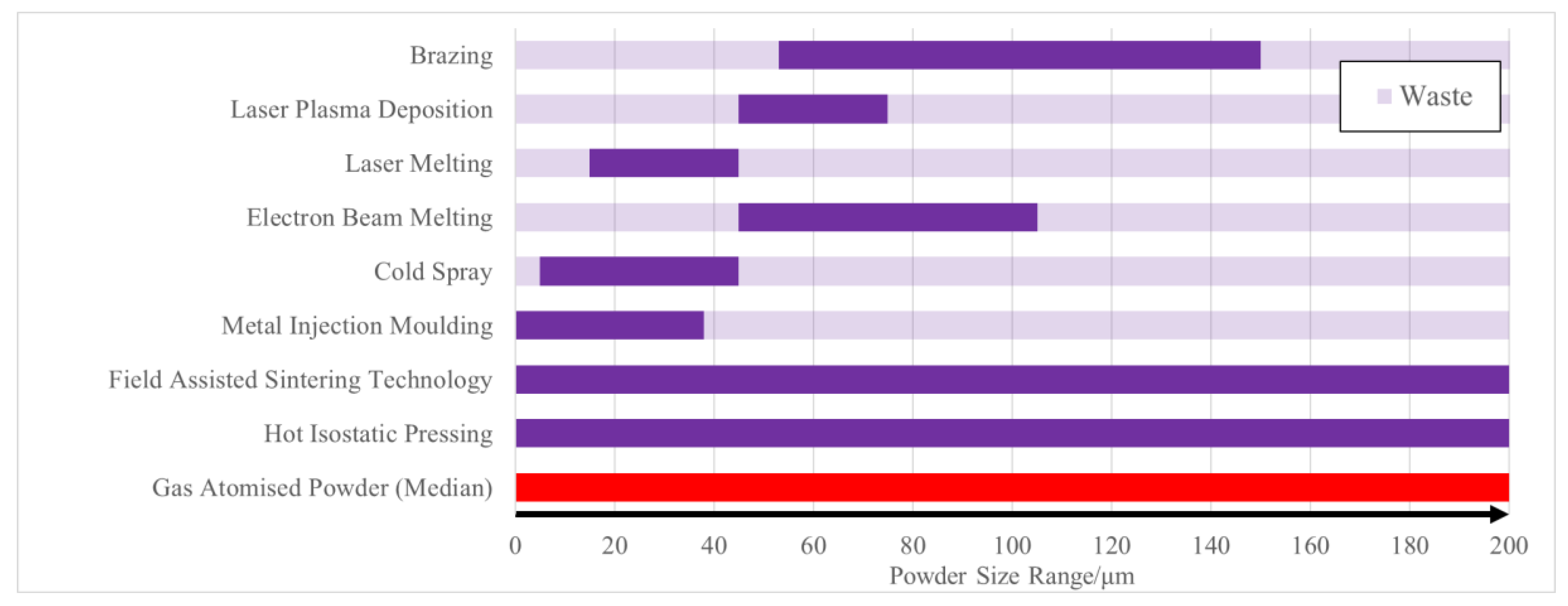
In recent years, there has been significant attention on the use of powder-based additive manufacturing in the production of components in the aerospace, medical and automotive sectors. The ability to produce near-net shape components at a faster rate and with less material waste is a clear advantage of these processes; however, they require high-quality spherical powders [1] to produce high-quality components. An increase in powder production to supply the AM sector comes with the inevitable generation of unusable waste material. Typically, this relates to powders which are non-spherical, too small/large for the process, or that have already been AM processed and therefore cannot be reused due to an increase in interstitial elements such as oxygen and nitrogen. Examples of the size ranges required for various AM processes, compared to other powder metallurgy routes and to typical gas atomised (GA) powder sizes [2], are shown in Figure 1. In the case of gas atomisation, up to 65% of the powder [3] could be out of specification for powder-based additive manufacturing processes. Many AM powder producers are stockpiling powder and need alternative recycling options in order to make AM processes more sustainable.
One of the most desirable materials for use in AM is titanium. This is because near-net-shape components produced via AM could result in reduced costs, due to the reduction in the amount of wasted material: Up to 95% of a forged billet can be machined off during the production of aerospace components [6]. In summary, AM is beneficial in that it can produce high-quality near-net shape components at a much-improved buy-to-fly ratio [7]. The increase in waste material from the production of powders specifically required for AM processes is a potential issue that could be mitigated through recycling and the use of wire deposition additive processes; such near-net shape manufacturing processes for titanium were reviewed in Reference [8].
Recycling titanium waste is a common practice, but it is not reverted to high-performance products, due to its strong affinity to embrittling interstitial elements, lack of cleanliness and the high chance for contamination with high-density inclusions. Current recycling processes include additions in the form of lumps of cored wire into steelmaking, where any contamination can be reduced by the steelmaking processes. More novel methods utilise severe plastic deformation (SPD) to produce a higher-quality material from the waste that can be produced at a low cost. One such example is equal-channel angular pressing (ECAP). ECAP is an SPD process that takes a solid metal billet and forces it through a 90° channel in the ECAP die [9]. The resulting material has been reported to have improved hardness and strength, as compared to those produced through the use of traditional methods, such as forging and extrusion [10]. There have been examples of ECAP where the feedstocks have been particulate, rather than a solid billet, allowing for the recycling of waste [11,12]. Despite this, one of the largest drawbacks of ECAP is that it is a batch process and can be operated only on small samples [13], which reduces the attractiveness of the process on industrial scales. Recently, it has been demonstrated that titanium alloy swarf can be recycled and fully consolidated into near-net shapes by using the emerging solid-state FAST-forge process [14].
This paper describes a solid-state method for consolidating out-of-specification titanium powders and waste swarf titanium directly into wire, which, after subsequent wiredrawing, could be used in metal wire deposition AM processes or as a consumable filler wire in fusion welding, such as tungsten inert gas (TIG) welding. For wire deposition AM technologies, a major mechanical property requirement is wire ductility that permits the feedstock to be coiled and unwound without fracturing.
The direct consolidation, solid-state continuous process—ConformTM—was first developed by Green for the UKAEA (United Kingdom Atomic Energy Authority), in Preston, UK, in the early 1970s and has been in use since [15,16]. It was invented to recycle electrical components from waste aluminium and copper electrical conductors. Research into the ConformTM process has recently turned toward the use of both titanium and powder feedstocks. Palan et al. [17,18] have reported ultra-fine-grained commercially pure titanium wire produced through multiple-pass ConformTM, coupled with rotary swaging. Wilson et al. [19] attempted to use ConformTM to produce titanium alloy wire from powders, at 900 °C, in an argon atmosphere. The main drawback is that an inert atmosphere is expensive to implement and use. For the ConformTM process, there has been no evidence to date to suggest that an inert atmosphere for feedstocks increases the product quality. The heating of the powder is also an additional step that may be unnecessary to the process; as the process increases pressure and heat through friction, the preheating of the material would be obsolete. Work at The University of Sheffield with commercially pure titanium (CP-Ti) hydride-dehydride (HDH) powder [20] demonstrated successful Conform™ extrusion without the need for feedstock preheating or an inert atmosphere.
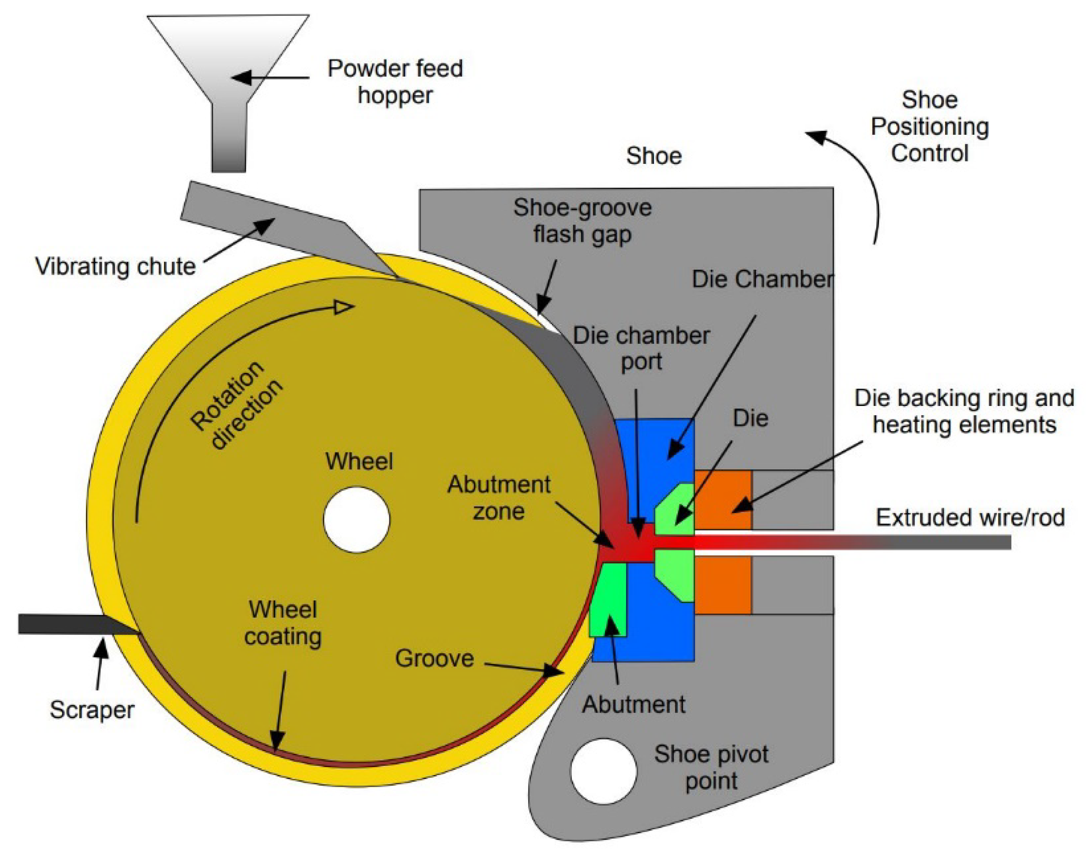
Knowledge of how particulate materials are processed through a ConformTM machine is still immature when compared to that of conventional metalworking processes. It has been suggested that powder particles are sheared in the grip region of the wheel groove, which then generates the heat and pressure for the particles to weld together and material to be extruded. This process is a continuous extrusion process and follows a similar layout, as shown in Figure 2. The powder is fed into the groove of the wheel at its apex. As the wheel rotates, the particulate feedstock flows into the groove until it meets the abutment tool, which protrudes into the groove. As more powder is processed, it heats up through the inter-particle friction, adiabatic heating of compressed particles and conduction from the tooling. This causes the titanium alloy particles to soften and deform, increasing the density of material above the abutment. Once the pressure and temperature are high enough, the material is extruded through a shaped die positioned radially to the wheel. Although it could be assumed that the continuous nature of the process means that a steady state is achieved, it is entirely feasible that this may not be the case.
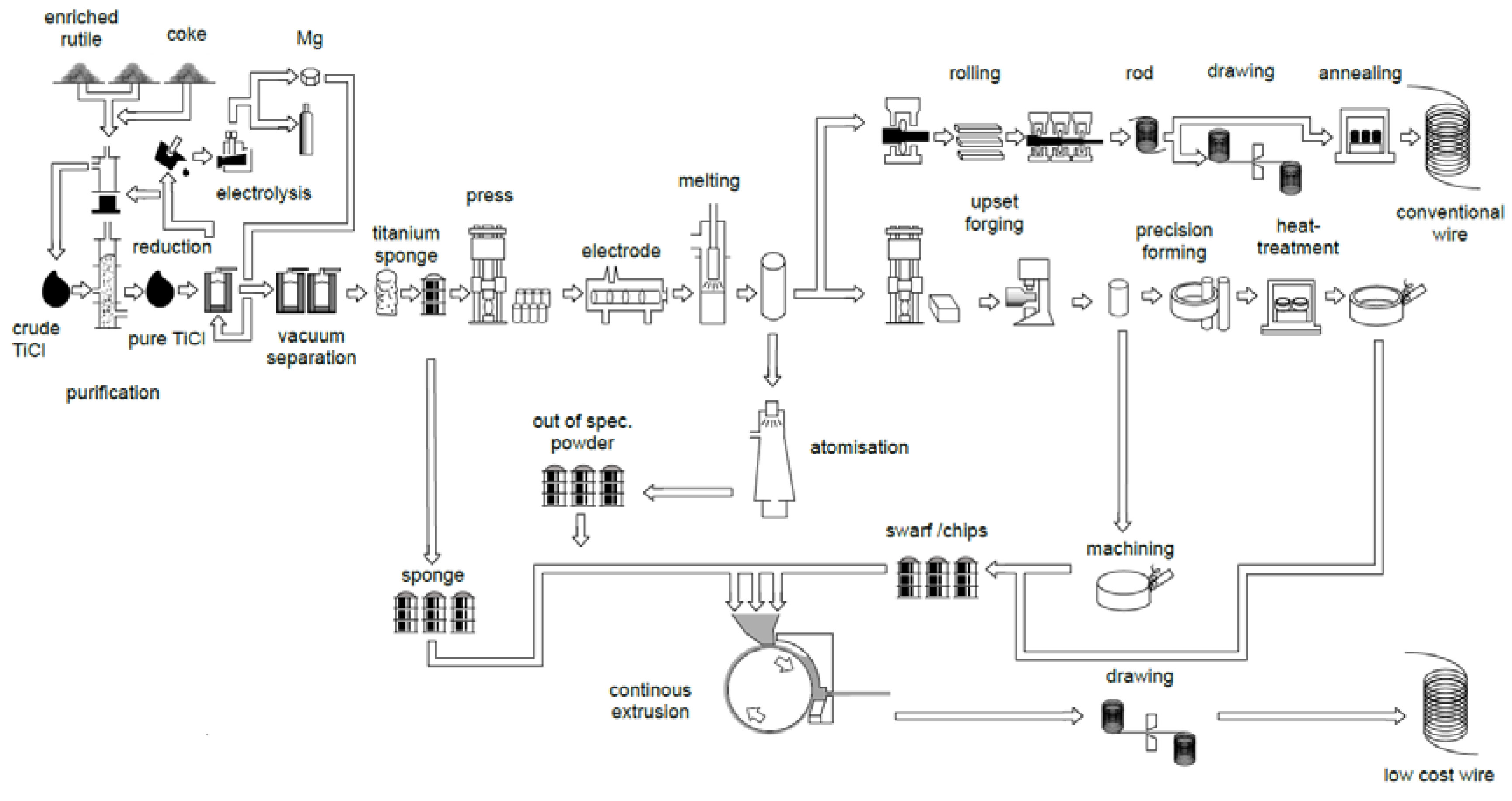
ConformTM is often found coupled with ECAP in the literature [21], and the combination of the two methods allows for an increase in the productivity of the ECAP process. However, it is possible to use ConformTM as a standalone process, and, therefore, it is advantageous over processes such as ECAP, as it is continuous, can be used with a vast array of feedstocks and can produce ultra-fine-grained material. Ultimately, the ConformTM process is a disruptive technology, as it is a potential recycling process that would result in a high-quality wire for laser metal AM or welding processes. Currently, the production of conventional titanium wire is an expensive multistep batch process involving the Kroll extraction process (titanium sponge), vacuum arc melting, multistep rolling and drawing, as highlighted in Figure 3. ConformTM is a disruptive technology, in that it provides a single-step continuous process for recycling waste from gas atomisation, the machining of forged billets (swarf) and additive manufacturing.
The aim of this paper is to outline the process and parameters used to consolidate oversized gas atomised Ti-6Al-4V (GA), CP-Ti HDH and machining swarf waste into wire, using ConformTM. Furthermore, in the case of CP-Ti HDH, especially, additional cold wiredrawing could produce affordable wire feedstock for fusion welding processes and direct energy deposition AM processes.
2. Materials and Methods
2.1. Powder Characteristics
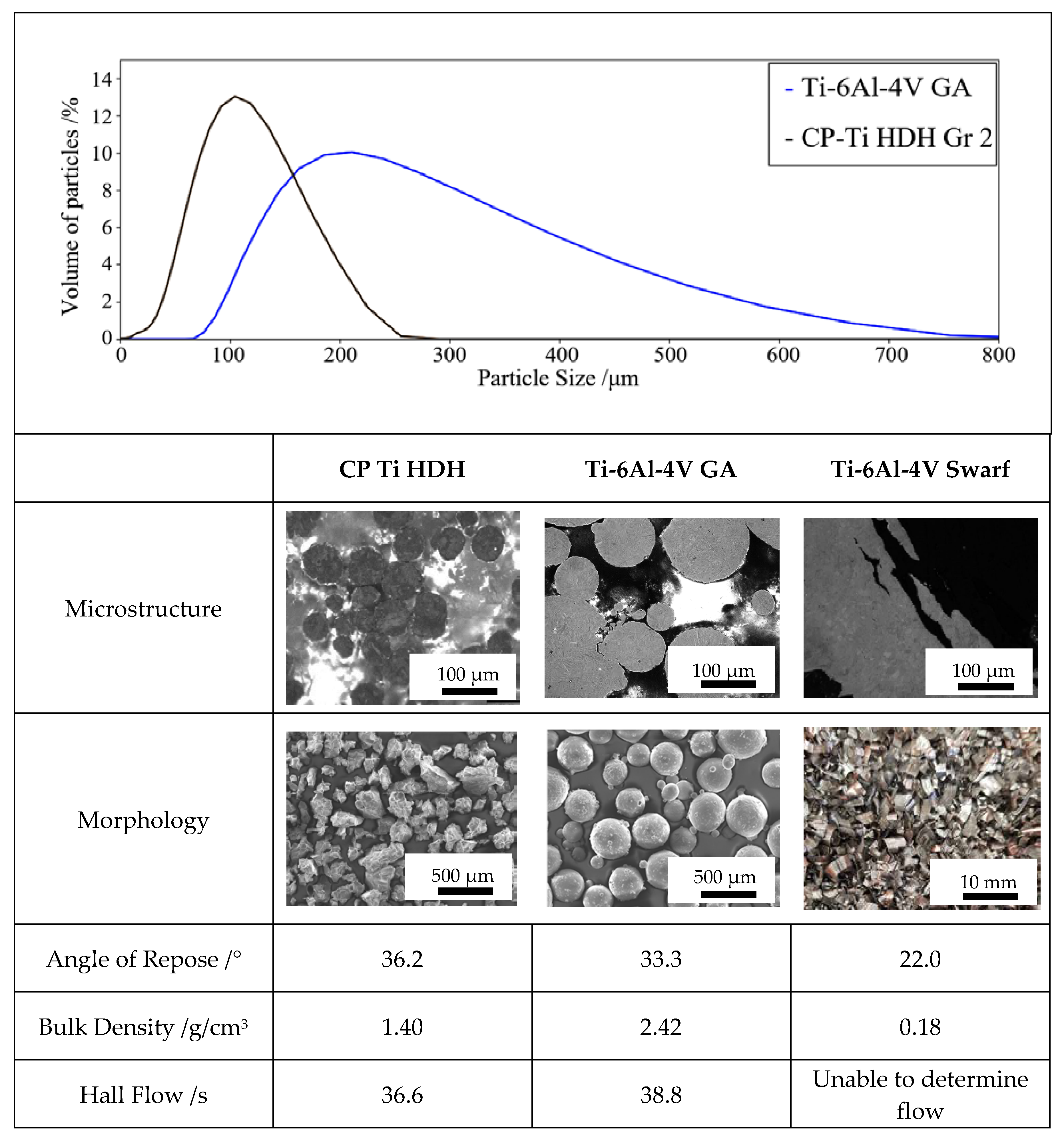
Three materials were used during this work: grade 2 commercially pure titanium hydride-dehydride (CP-Ti Gr 2 HDH) powder with a 45–150 μm size fraction from Phelly Materials Inc., Upper Saddle River, NJ, USA, Ti-6Al-4V gas atomised (GA) powder with a size fraction of 67–750 μm from Puris LCC, USA and Ti-6Al-4V (ASTM Grade 5) machining swarf from Airbus, St Eloi, Toulouse, France. The Ti-6Al-4V GA powder was made up from three different sieve fractions remaining from previous batches of powder from additive manufacturing collaborators that was then re-blended into a single batch. All of these recycled sieve fractions were from the same original atomisation batch. The material was used as received, with any cleaning completed by the suppliers, using proprietary cleaning methods. Oxygen analysis via inert gas fusion was provided by the Ti-6Al-4V GA supplier, 0.15 ± 0.02%. The CP-Ti Gr 2 HDH powder was also found through inert gas fusion by the supplier, Phelly Materials Inc., and found to be between 0.14% and 0.20%.
The size ranges of the powder were determined via laser scattering, using a Malvern MasterSizer 3000, and estimated by sieving the swarf. The morphology of the powder was determined from SEM and light microscopy.
CP-Ti Gr 2 HDH has an irregular and angular morphology, due to the hydride-dehydride process, whereby the metal is mechanically crushed into a powder. The Ti-6Al-4V GA powder contains primarily spherical particles from the gas atomisation process with a high percentage, also observed to have attached satellite particles. The particle size distributions for the feedstocks are given in Figure 4. The swarf was of various sizes, in both length and width, ranging from 0.3 to 1.0 mm in thickness, through to 10 mm in length, with some curvature to the structure typical of material generated through machining processes.
2.2. Conform Extrusion
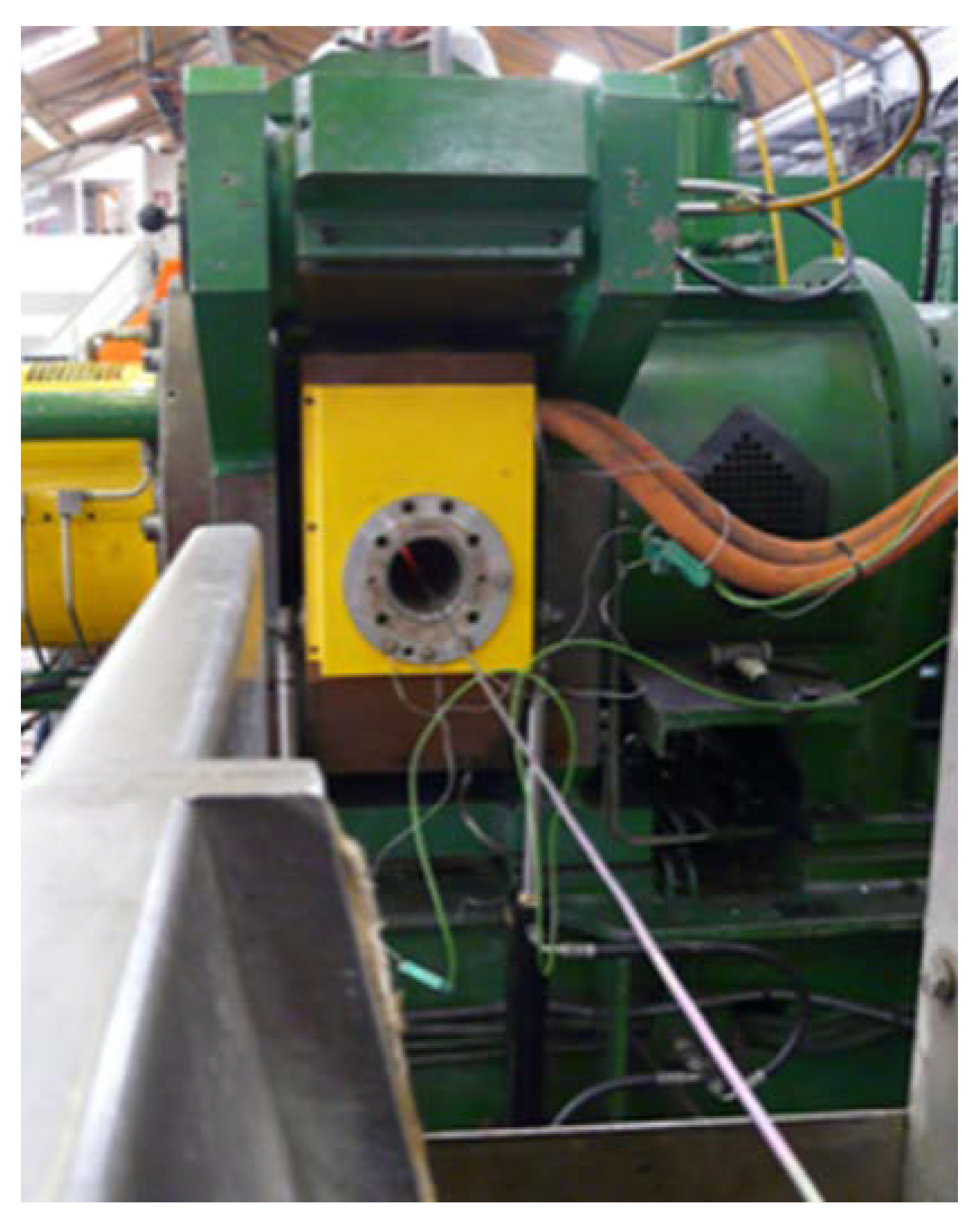
A BWE ConformTM 350i machine situated at BWE Ltd., Ashford, UK, was used for the trial extrusions (Figure 5). Bespoke tooling was designed specifically for the processing of titanium powders based on theoretical calculations by Thomas [22]. The primary reason for different tool dimensions was to account for the larger particle size of the machining swarf, to allow sufficient material to be fed effectively into the wheel groove. The key geometry parameters are listed in Table 1 and are scaled from conventional BWE tool geometries. Abutment materials were chosen for their high hot strength, following previous extrusion trials conducted by Thomas et al. [20], where Stellite™ abutments were used. While it is an extremely hard material, Stellite™ can be brittle, and abutments made from this can fracture early in the process, preventing successful extrusion from titanium powders. In the case of softer, weaker metals such as aluminium and copper, Stellite™ and cheaper tool materials can be used effectively. For the extrusion of titanium in this study, abutments were machined from more-exotic materials.
The die and die chamber were preheated to 500 °C, but the wheel was not preheated, as it was believed that the heat generated from friction between the feedstock and tooling during the Conform™ process was sufficient to heat the wheel during the initial stages of the trial. Typically, the temperature at the abutment face farthest away from the feedstock can increase to a temperature between 600 to 900 °C. The as-received powders/swarf were manually poured into a vibrating chute at the top of the wheel, where it was conveyed into a groove. The powder feed was moderated according to the observed extrusion pressure, as determined from the current draw by the machine’s drive motor.
It is worth noting that this process was conducted without the preheating of powder/particulate feedstock and without inert gas shielding.
CP-Ti Gr 2 HDH powder was fed into the machine first and used to preheat the wheel, coat the groove and to achieve an initial build-up of pressure for extrusion, without contaminating the product or prematurely abrading the tools. Previously, preliminary investigations have shown that using Ti-6Al-4V from the start of the trial resulted in tooling wear and premature abutment failure. During this heat-up phase, the powder feed rate was at its highest, i.e., 0.5–1.0 kg/min, before being reduced, as the titanium wire started to extrude. The main process feedstock was added when it was determined that the extrusion was beginning to reach a steady state, as determined from measured tool temperatures and the wheel motor current. The wheel speed was kept at a constant 6 RPM for the full duration of each trial. Once clear of the die, the extruded wire was guided through a water trough for quenching. Sample 1 was extruded early in the process when the feedstock was 100% CP-Ti, and Sample 5 was extruded last, when the feedstock was 100% Ti-6Al-4V. The samples between these points were taken equidistantly across the length of the extruded material.
2.3. Cold Drawing
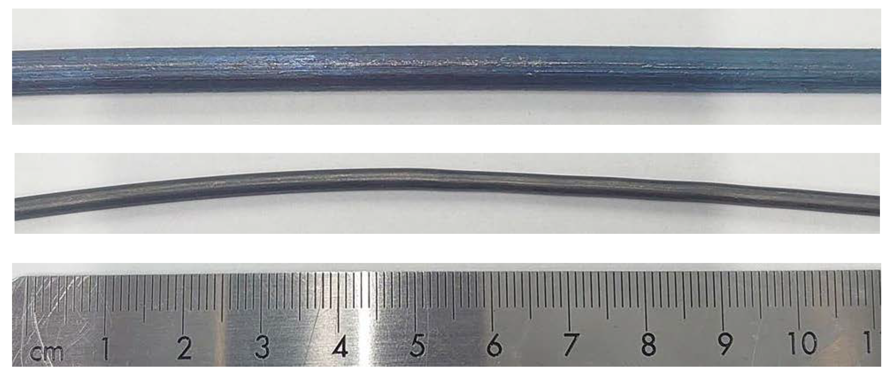
As-extruded CP-Ti Gr 2 HDH from the smaller toolset was cold-wire-drawn, with the intention of performing additive manufacturing trials in the future. The dies used were 4.09, 3.50 and 3.00 mm in diameter, to give an average 28% reduction for each pass. After each pass, the wire was stress-relieved at 700 °C, for 30 min, without a protective atmosphere. A thin (approximately 50 µm), oxide layer formed during heat treatment aided the cold-wiredrawing process, as the thin oxide layer spalled off as the wire entered the drawing die and added to the applied zinc stearate lubricant. This resulted in a bright, smooth surface finish in the final wire, as can be seen in Figure 6.
2.4. Characterisation
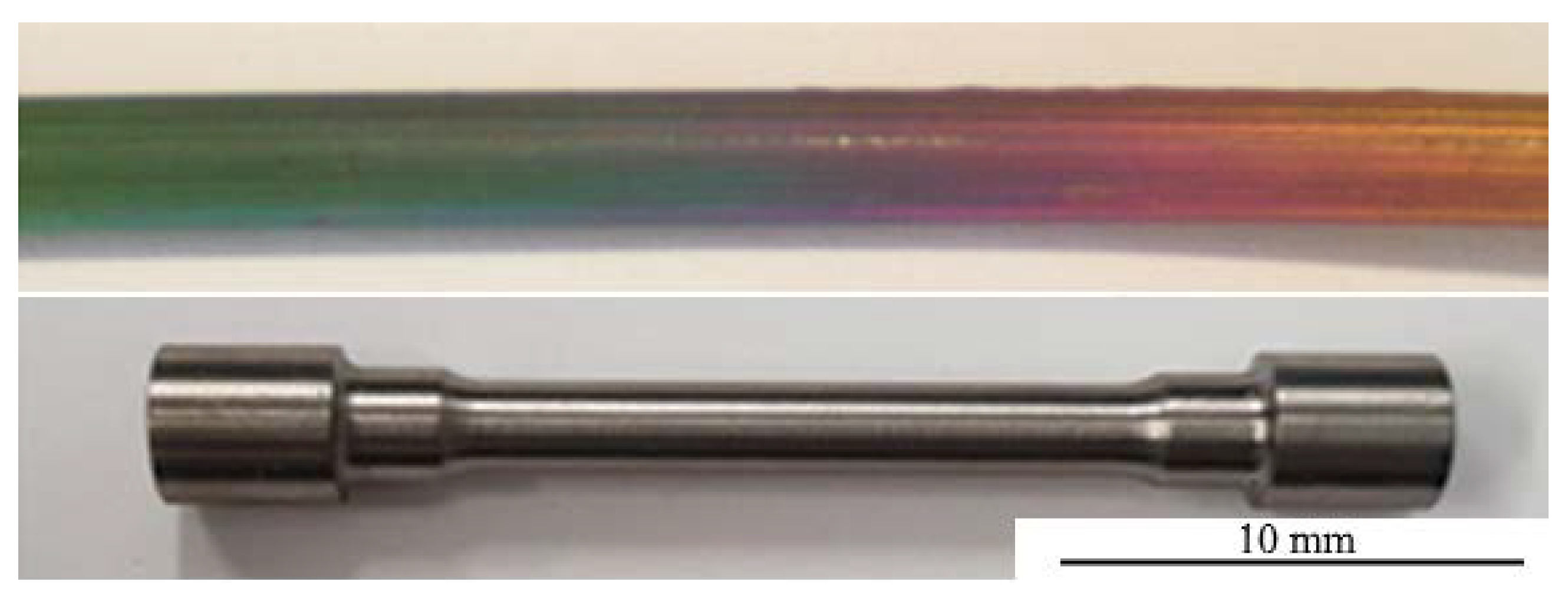
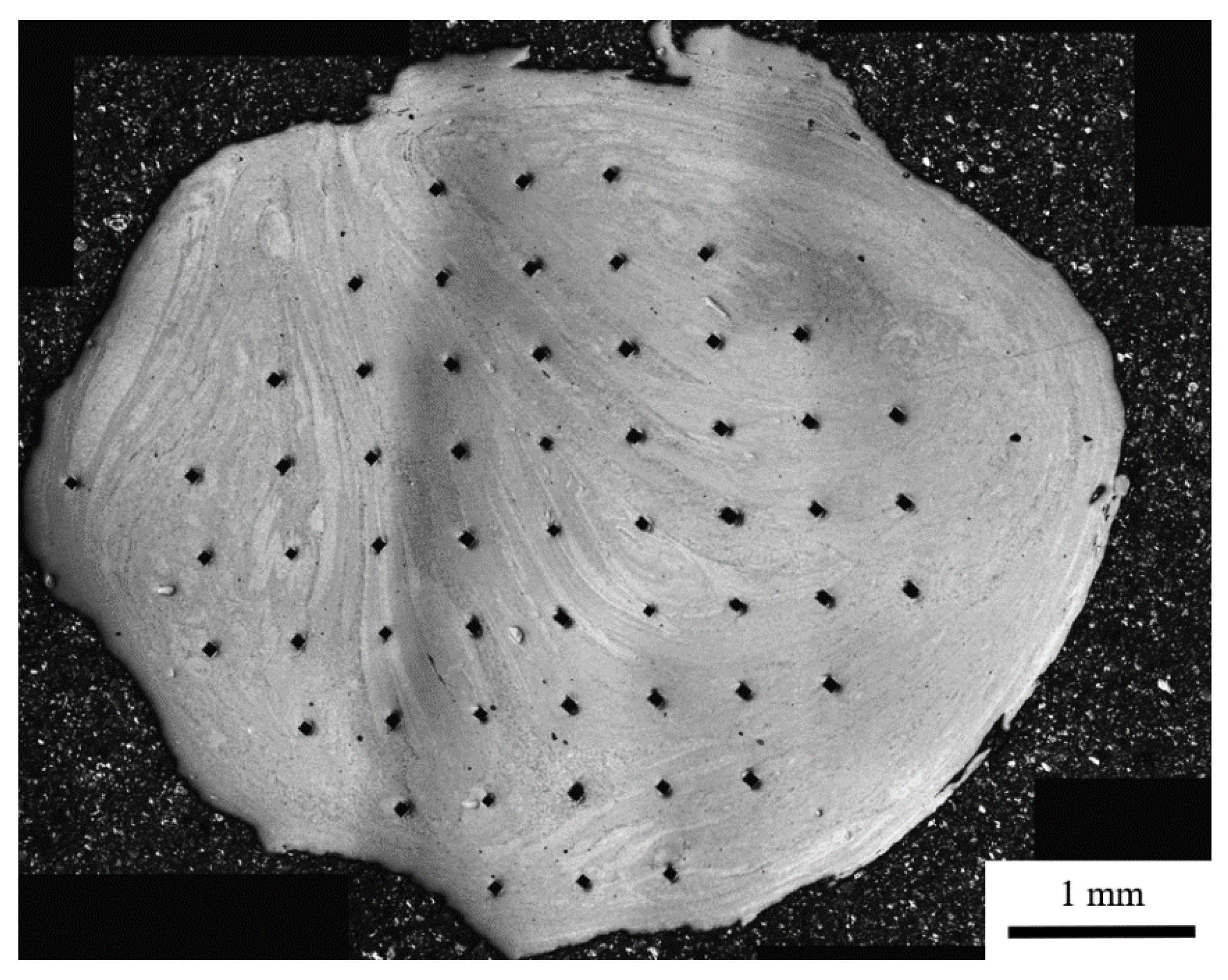
Samples 1–5 for each trial were prepared by using a standard preparation routine until a final mechanical–chemical polish with a silica/H2O2 suspension, and the microstructure was investigated by using cross-polarised light microscopy. Porosity and grain size were determined from the light micrographs, using image analysis and the linear intercept method, respectively. Higher-resolution microscopy was conducted by using an FEI Inspect F50 scanning electron microscope in backscattered electron imaging mode. Tensile specimens were machined from the as-extruded wire and tested to failure, at ambient temperature, according to ASTM E8/E8M-15a. Due to the surface finish of the material, the samples were prepared with a 2.50 mm gauge diameter and a 15.00 mm gauge length. An example is shown in Figure 7. The tensile specimens were taken from the area directly adjacent to the metallographic specimens, so they can be assumed to have been processed under the sample conditions. It should be noted that, in the case of the swarf-extruded wire, the poor surface finish, which is demonstrated in Figure 8, and high curvature restricted the extraction of tensile specimens to three due to difficulties in gripping the wire during machining. Additionally, any errors determined for the results of the tensile testing were derived from measurement of the final samples and tensile testing errors. Microhardness was recorded in an array across the sample cross-sections (see example in Figure 8), using HV1 with a dwell time of 15 s and indents every 0.5 mm. This was conducted by using a Struers DuraScan 70.
3. Results
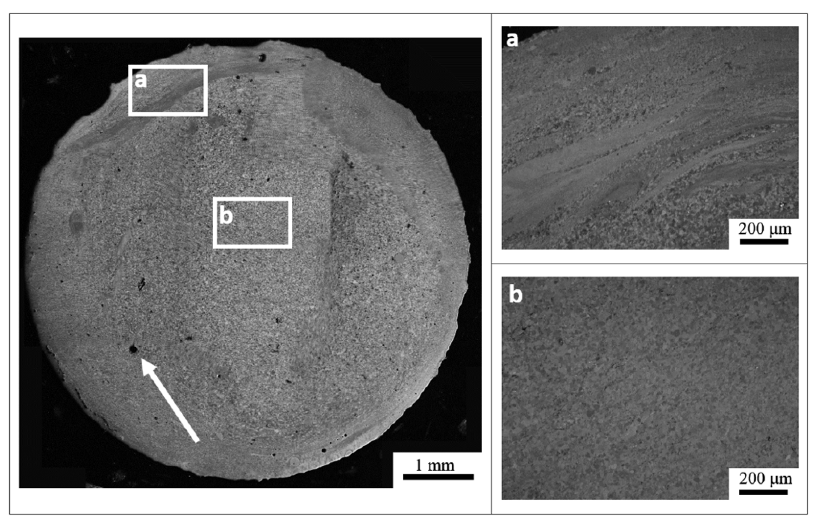
The as-extruded wire has a distinctive macrostructure in its cross-section that is particularly visible early in the process when temperatures and extrusion speeds are relatively low. Figure 8 gives an example of this structure, where two distinct areas can be identified, the inner equiaxed microstructure (Figure 9a) and the outer rings/layers (Figure 9b).
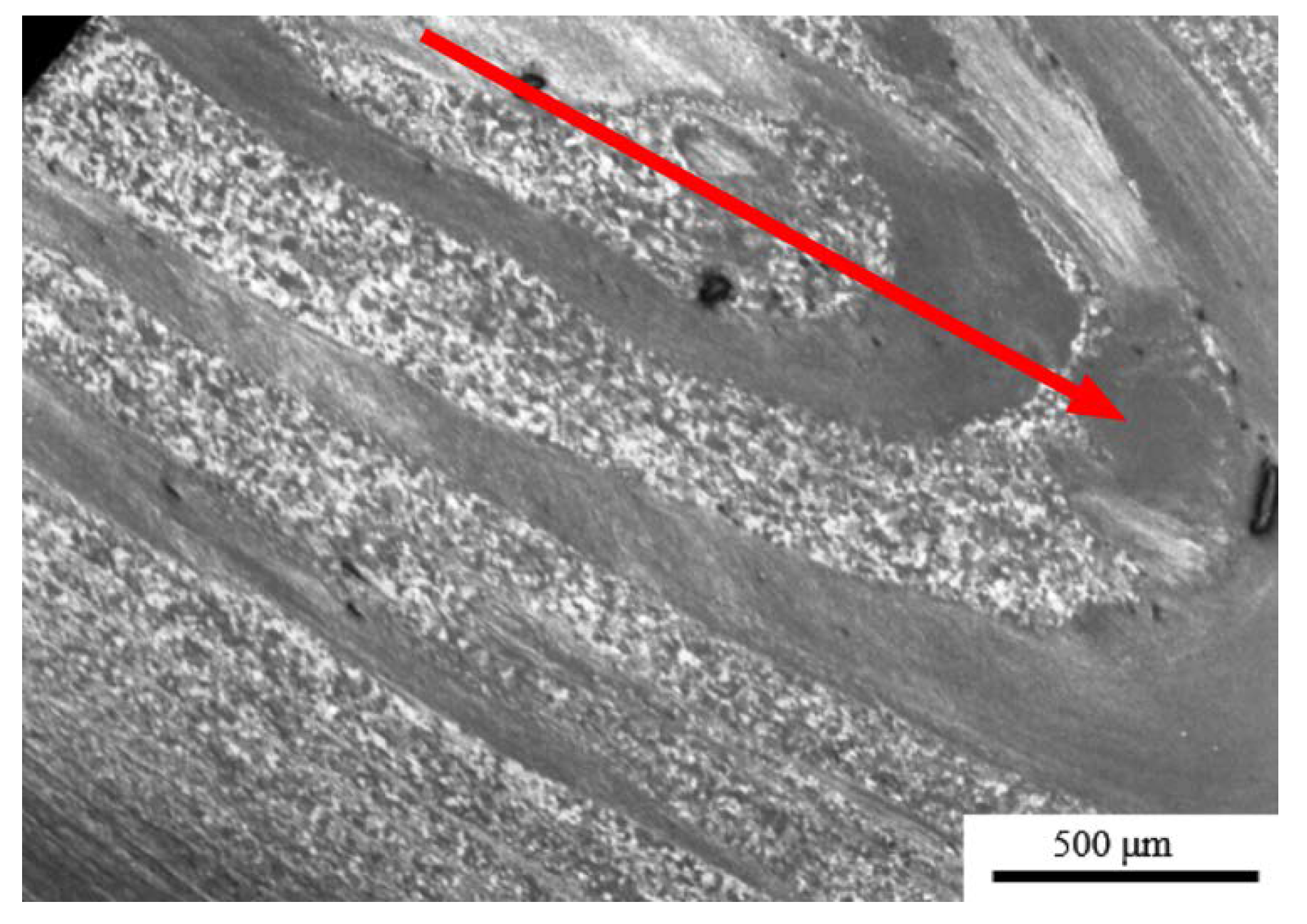
Previous work has shown that the viscoplastic behaviour of aluminium alloys in the region of the abutment and die in Conform™ results in flow behaviour similar to that of fluid in a pipe [23,24]. This flow results in a shell–core structure where material moves fastest through the centre of the die, creating a shear between the core and shell, helping to refine the microstructure. Further evidence of this flow is observed in work completed by Etherington in 1978 [25], where a transverse section of the rod produced from the extrusion of OFHC (oxygen-free high-conductivity copper) demonstrates flow lines, much like those found in this work. This suggests that material is not necessarily extruded in the same order in which it entered the process. The transverse direction further demonstrates this flow structure, with evidence of flow direction being demonstrated by the wave-like structure across the sample (Figure 10). This same structure is replicated in the swarf material, as can be seen in the cross-section of the material shown in Figure 8.
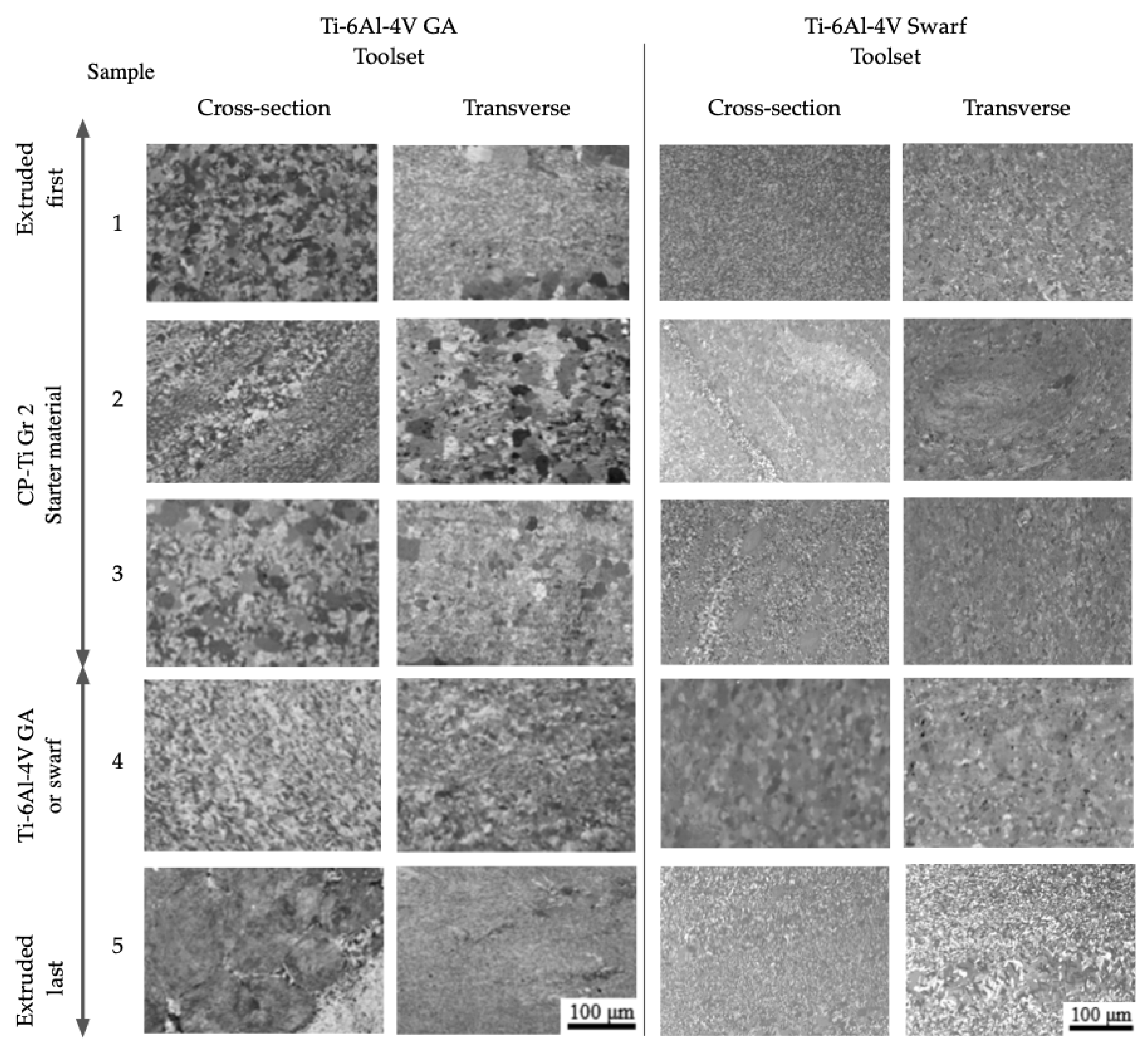
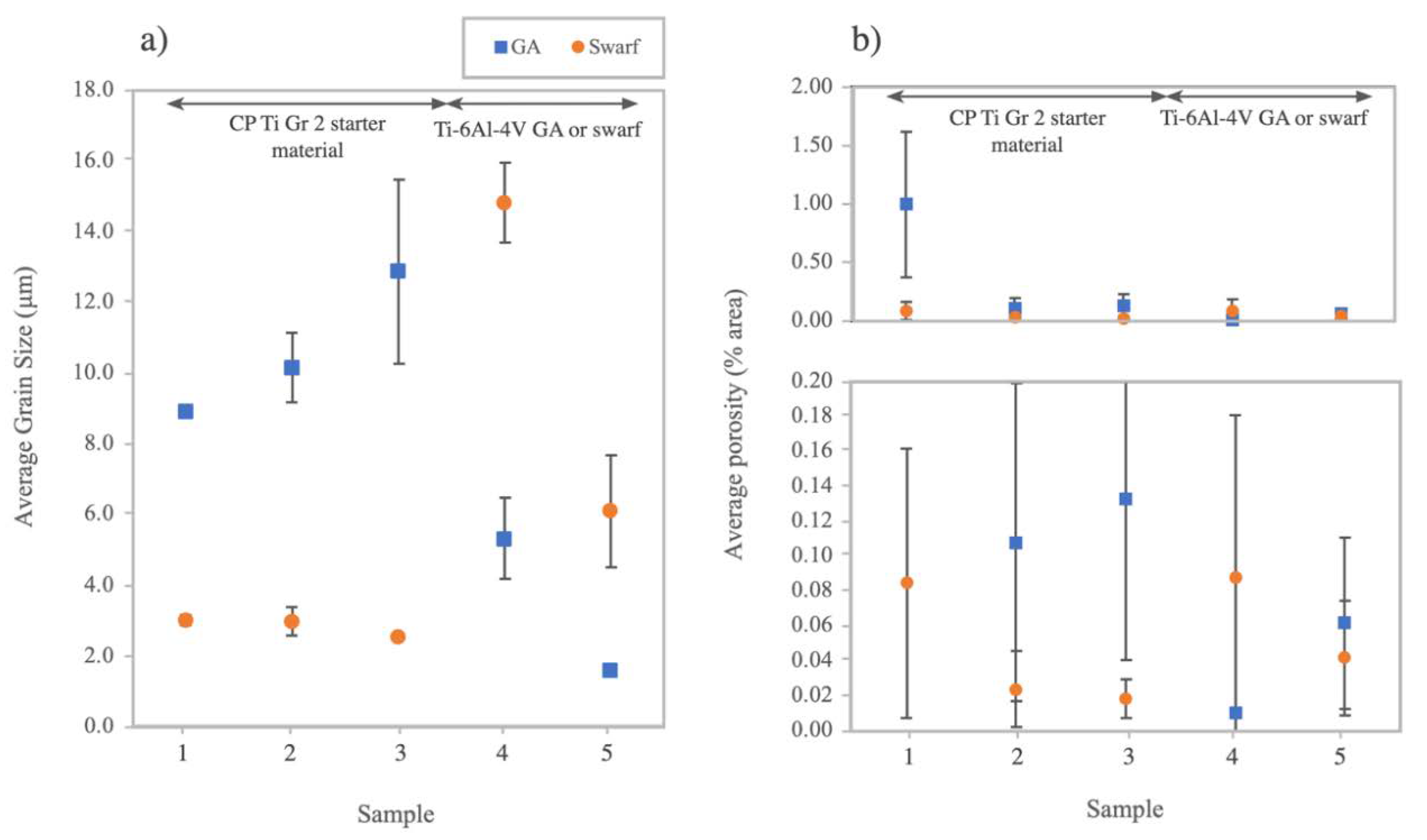
The evolution in grain size and porosity for the GA powder and swarf-derived Ti-6Al-4V wire at different sample locations varied significantly from the initial extruded wire through to the back end of the extrusion (i.e., Samples 1 through 5, respectively). The grain sizes and porosity levels were measured from high-magnification light micrographs shown in Figure 11 and plotted in Figure 12.
The initial microstructure in the Ti-6Al-4V GA wire is moderately fine-grained, with average grain sizes below 20 μm (as shown in Figure 12a). There are some areas of very fine grains (2–5 µm) and others of larger 30–50 µm grains that are segregated in areas that mirror the macrostructure flow patterns seen in Figure 8. Some samples exhibit prior particle boundaries, indicating inconsistent consolidation of the powder, and these are more pronounced in samples extruded earlier in the process, where temperatures and pressures are lower. As Figure 12b demonstrates, there is a small amount of porosity which could be attributed to there being insufficient pressure to fully consolidate the material early in the process. During the warm-up phase with CP-Ti powder (Samples 1–3), there was a slight increase in the both the average and variance of the grain size observed in wire produced during the Ti-6Al-4V GA trial. This contrasts with wire produced early in the swarf trial that was more homogenous, with a much smaller average grain size, during the early stages. Once the Ti-6Al-4V GA powder was fed into the machine (Samples 4 and 5), the average grain size of the wire dropped sharply, primarily due to the inherent smaller initial grain size of the powder feedstock. However, it also continued to reduce as the extrusion progressed and further Ti-6Al-4V powder was fed into the machine. A similar trend occurred once the swarf feedstock was fed into the machine, with the initial grain size at Sample 4 reducing as the process progressed to Sample 5.
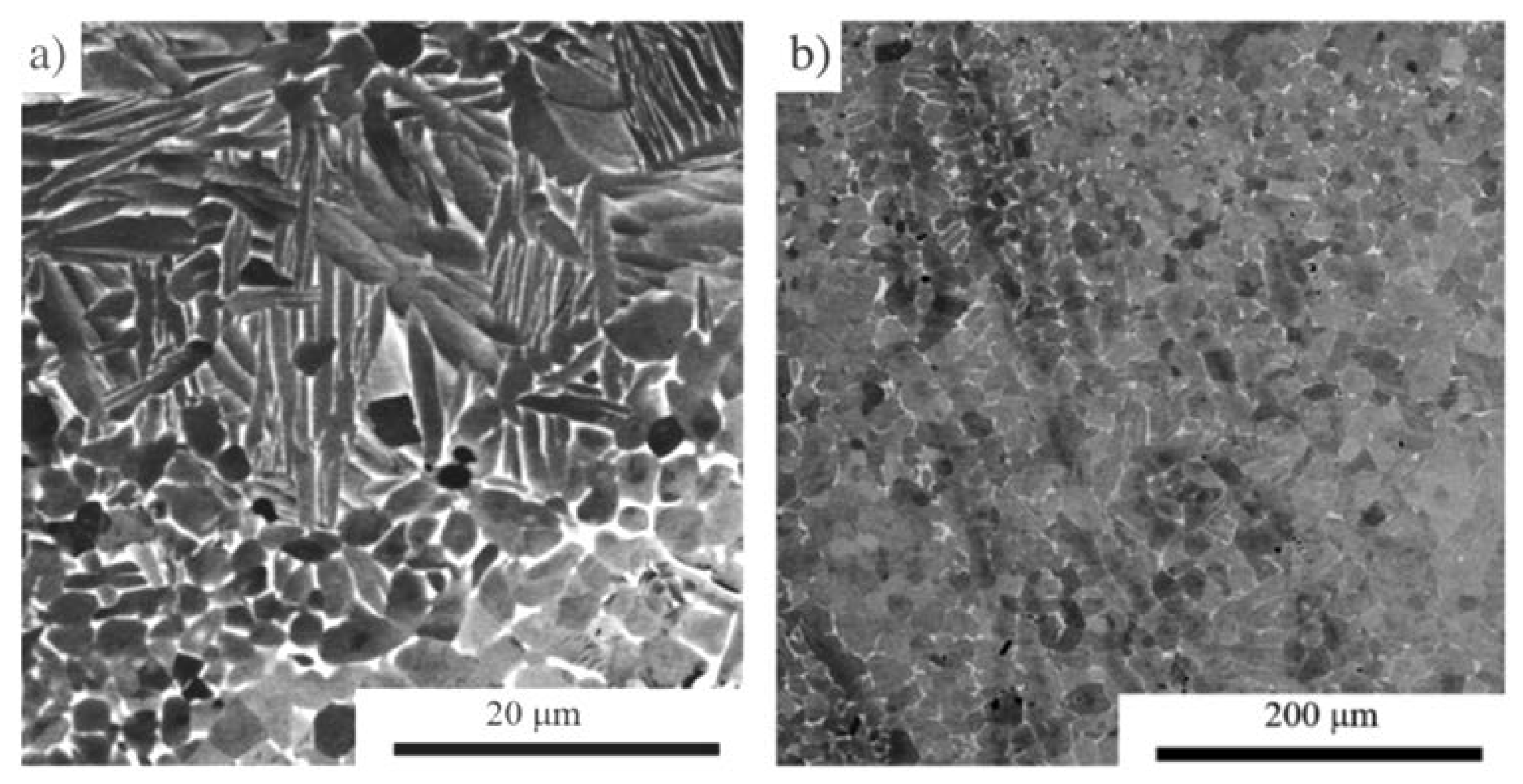
A single sample of wire containing the Ti-6Al-4V swarf was heat-treated at 1010 °C, for three hours, in order to qualitatively determine the degree of diffusion bonding between swarf particles and the matrix material. The microstructure of the starting material (in Figure 13a) shows a swarf particle consisting of alpha laths surrounded at the bottom of the micrograph by equiaxed alpha grains in a beta matrix. The heat treatment resulted in the annihilation of the alpha laths and production of the more-homogenous equiaxed microstructure without any visible prior particle boundaries (Figure 13b).
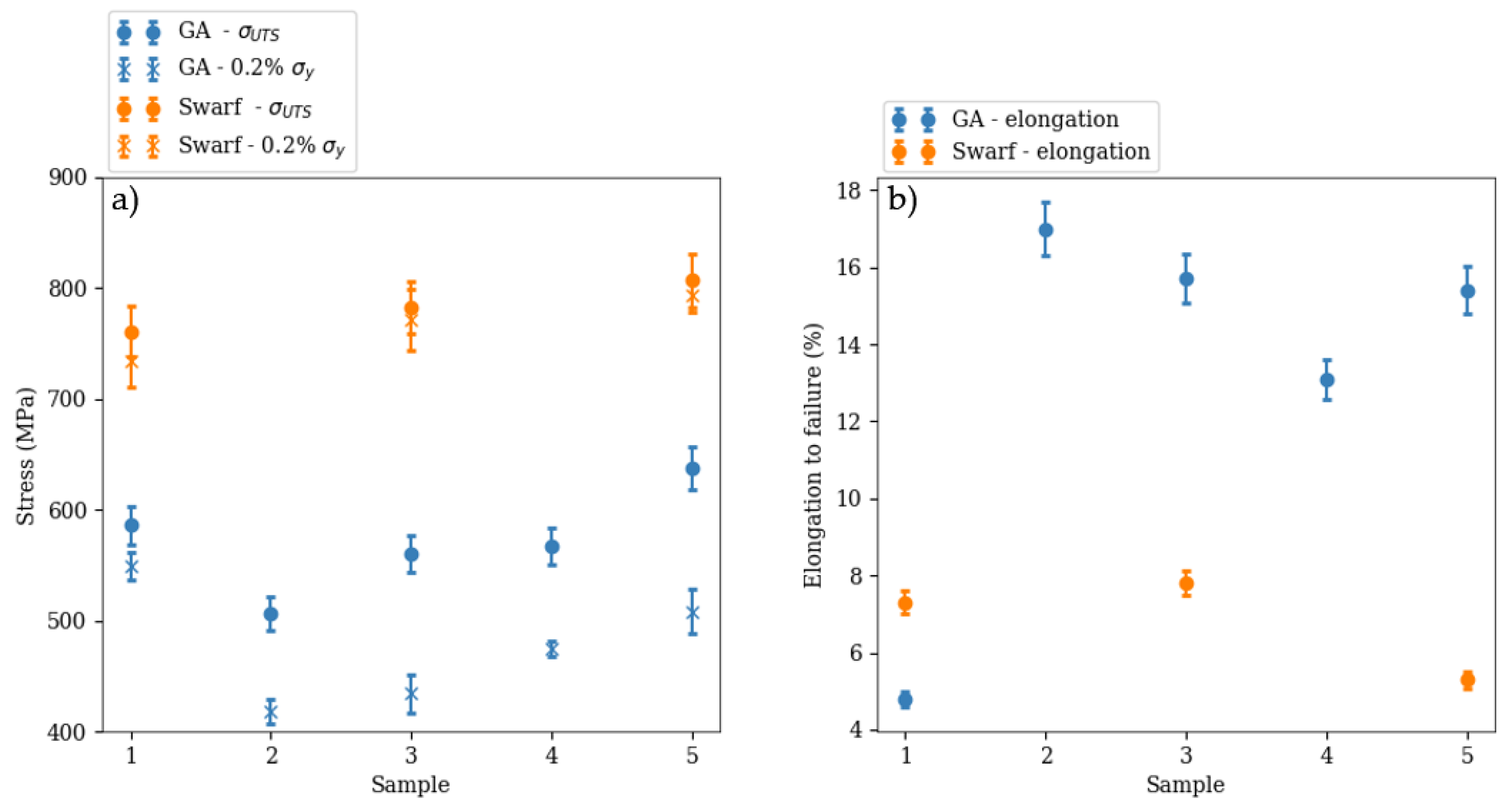
Using the sample geometry shown in Figure 7, we measured the room temperature tensile behaviour of the Ti-6Al-4V-extruded wires at different locations, from the initial extruded wire (Sample 1) through to the back end of the extrusion (Sample 5). The measured tensile properties for GA powder and swarf derived wires are plotted and compared in Figure 14.
Material taken from the first couple of metres of the extruded Ti-6Al-4V GA wire is made up of CP-Ti Gr 2 (Samples 1–3) and has a UTS of 550 ± 40 MPa, which is much higher than expected for CP-Ti Gr 2 (340 MPa [ASTM B265-15]) and is closer to the UTS for CP-Ti Gr 4 (shown in Figure 14). There is an early peak in strength for Sample 1, which is contrasted with the sample also having very low ductility, 4.8% elongation to failure. As the process continues and heats up, the yield strength and UTS initially reduce, but ductility improves, correlating with the porosity results shown in Figure 12b. As the process continues, the yield and UTS gradually increase further. For the Ti-6Al-4V swarf trial, all of the initial tensile samples exhibit excellent static strength characteristics when compared with the early samples in the Ti-6Al-4V GA trial, with a 64% increase in 0.2% yield strength and 42% increase in UTS. Despite improvements in these properties, the tensile ductility of samples was significantly lower for the swarf trial than the GA trial. This could be attributed to the generally lower grain sizes demonstrated in the microstructure and/or a higher interstitial content in the swarf-derived wire, as compared to the GA-derived wire.
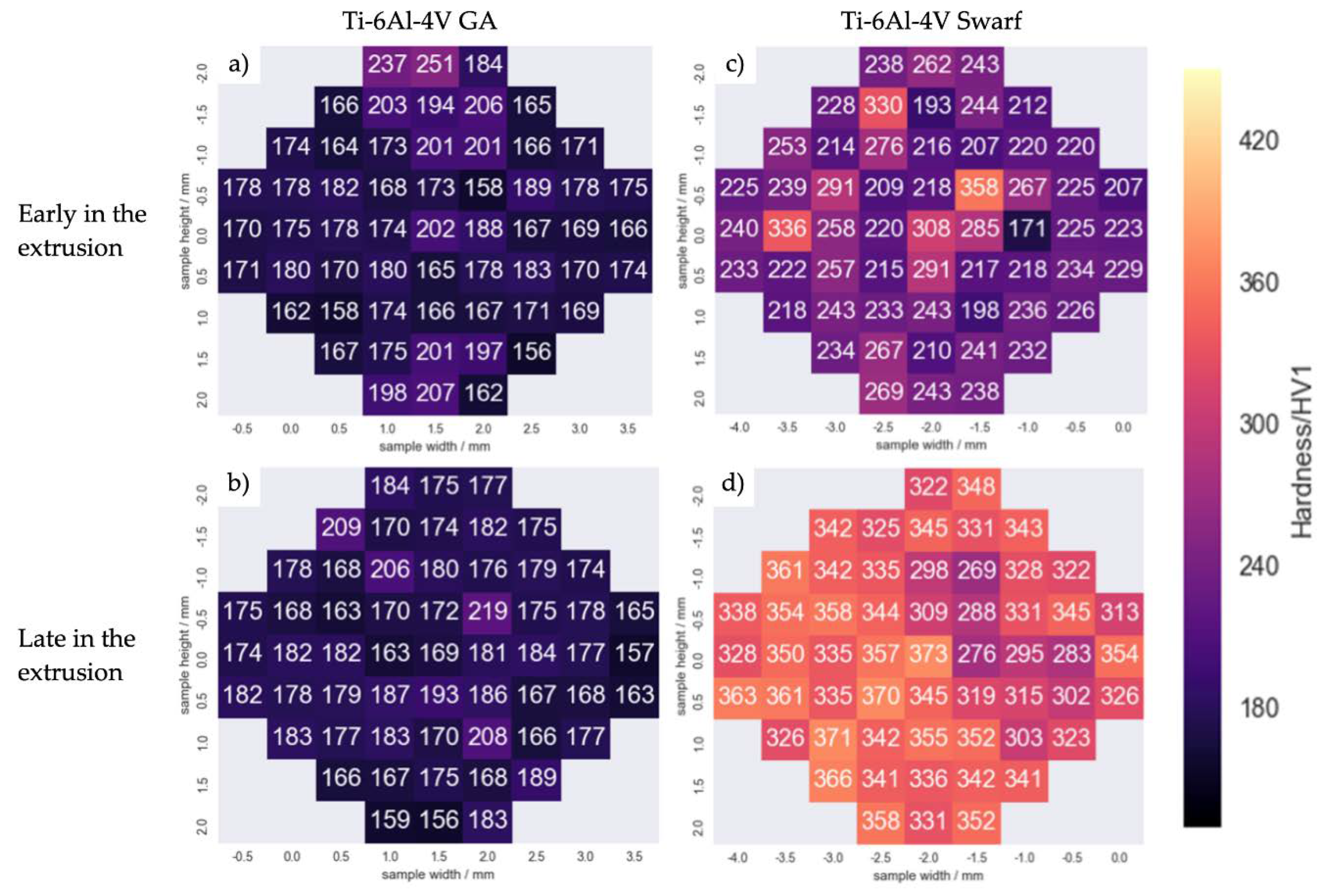
The Ti-6Al-4V GA wire microhardness shown in Figure 15 exhibited a similar trend to the tensile results, with no significant variation between samples extruded early and late in the process. There is also very little difference in the hardness observed across the cross-section of the wires. The initial results are taken from the first metre of material, where the extrusion has not yet reached steady state. The average hardness falls at 180 ± 20.32 HV1. The later results are lower at 177 ± 12.33 HV1; however, the result is much more consistent. The swarf wire has much larger results overall, with an average hardness of 241 ± 35.2 HV1 in the initially extruded material (c in Figure 15) and an even greater average of 334 ± 23.9 HV1 for material at the back end of the extrusion (d in Figure 15). Any areas in the initially extruded material with larger values can be attributed to undeformed particles or impurities, which can be seen in the microstructure of Sample 1, in Figure 11.
Wiredrawing
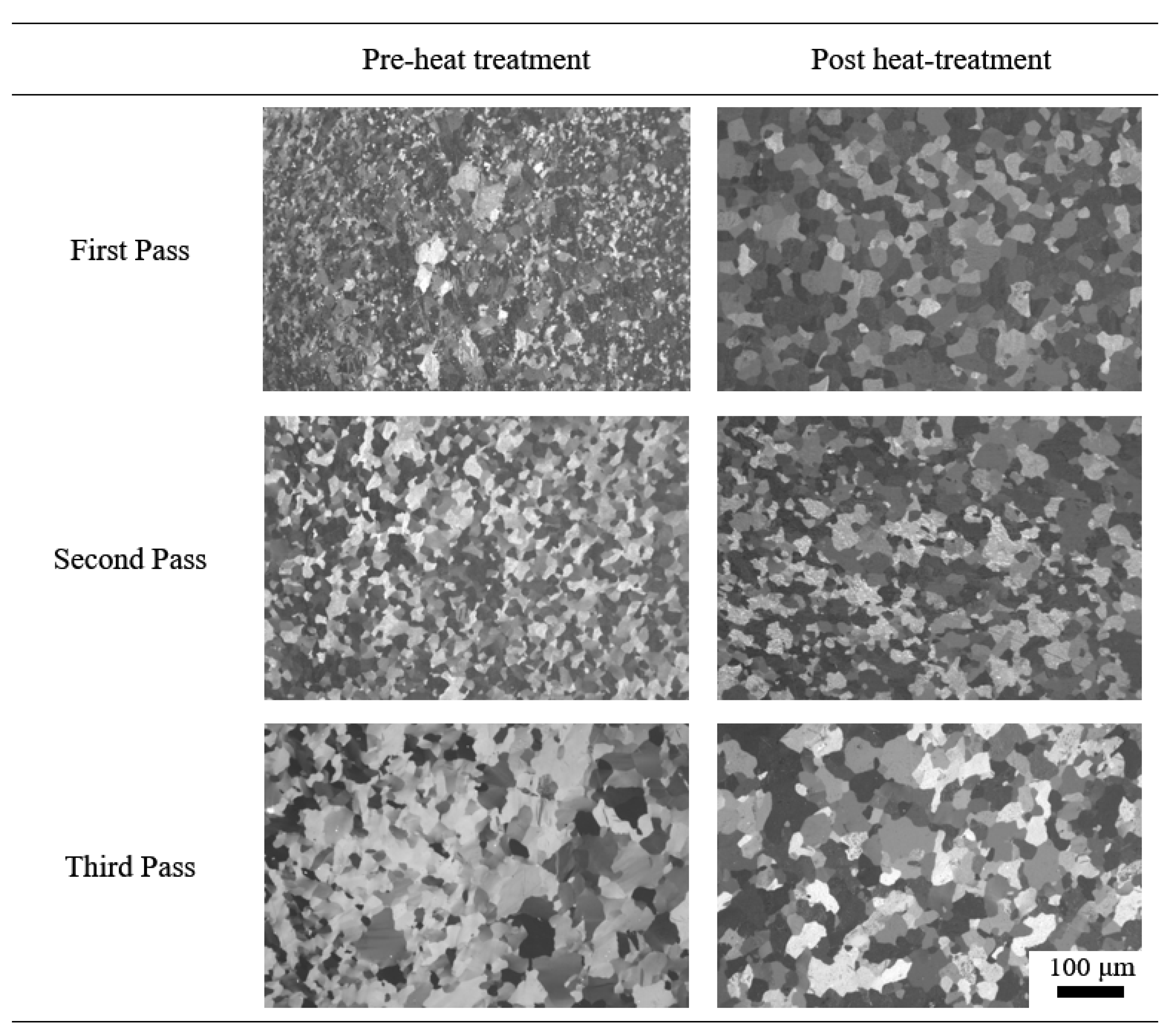
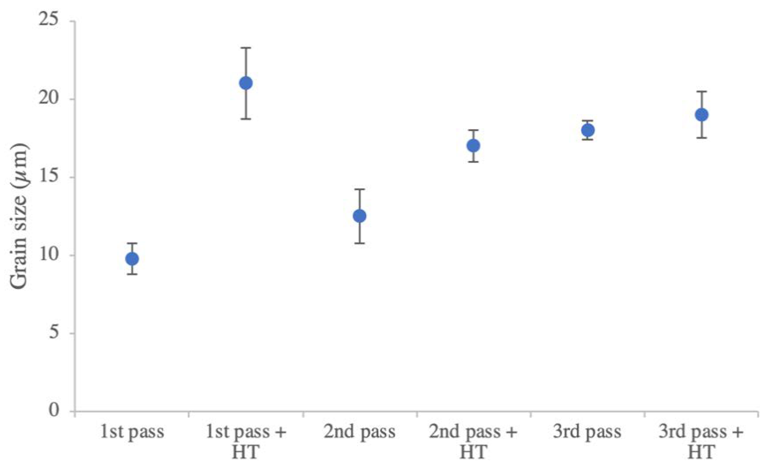
Conform™-extruded CP-Ti Gr 2 HDH wire from the smaller toolset was cold-drawn down into a wire with a 37% reduction in diameter after three passes. There is a distinct variation in the grain sizes across the material, with some grains being upward of 50 μm and others being less than 10 μm. This is similar to that observed in the parent material. The microstructural evolution during the wiredrawing is shown in Figure 16. There is a clear trend that shows, as the number of passes increases, there is a more homogeneous microstructure. This can be seen in Figure 17, where the grain size increases, but the deviation is much smaller.
Previous wiredrawing work has established that, through equal channel angular drawing (ECAP), it is possible to draw titanium wire with an ultra-fine-grained structure [26]. It should be noted that, between each pass, there was no heat treatment, which would ultimately result in grain growth. This ultra-fine grained structure had also previously been observed through multiple Conform™ passes, followed by rotary swaging [27]. The rotary-swaged wire was successfully cold-drawn down with an average 29% cross-sectional reduction, giving an overall reduction of ~64% from the initial wire diameter. Although this did not result in an overall reduction in the grain size, there was an improved uniformity of grains, resulting from static recrystallisation during the heat treatments. This recrystallisation has been demonstrated in previous work, and it has been shown that, at around a 56% reduction, recrystallisation of pure titanium can occur at temperatures of 500 °C and above [28].
4. Discussion
The results presented here show the evolution of three different materials throughout two different extrusion trials. Both trials were initiated by extruding CP-Ti Gr 2 HDH powders to heat up the tools and wheel, as well as providing suitable back pressure for the following materials of Ti-6Al-4V GA powder and Ti-6Al-4V machining swarf. Samples 1, 2 and 3 were found to contain 100% CP-Ti Gr 2, as expected from the feedstocks. During this early extrusion phase, tool temperatures are lower (at approximately 600–700 °C), as the wheel is coated in deformed powder and material builds up above the abutment; here, powder or solid material has a relatively long residence time in the tools, allowing powder particles time to bond together and for significant grain growth to occur. Fresh powder that is fed on top of existing consolidated material is incorporated into the bulk, further contributing to the material gripped by the wheel groove, which increases the extrusion pressure.
The reader should be reminded that each trial had a different tool setup and hence different potential extrusion pressures. The larger swarf tooling set had a required extrusion pressure of about 180 MPa lower than that for the gas atomised powder when CP-Ti Gr 2 HDH powder was extruded. For the larger toolset (i.e., swarf trial), it is clear that a far more homogenous extrusion product was generated with the CP-Ti Gr 2 HDH feedstock when compared with the smaller toolset for the gas atomised powder trial. The product was also produced at a steadier state, as indicated by the low variation in grain sizes, low porosity and excellent tensile properties presented above. In contrast, the CP-Ti extruded with the smaller toolset exhibited an unsteady product, with an increasing average grain size, as well as inhomogeneous microstructure. This causes the increased porosity to have a deleterious effect on the tensile properties. In both trials, the CP-Ti grain structure has differed from the material produced in other work. This is of particular interest in the trial that used the larger of the two toolsets, where the extruded product had a much-higher-than-expected yield strength and UTS when compared with the CP-Ti Gr 2 ASTM standard.
The reasons for these observations could stem from the extrusion toolsets, where the design for the GA powder required a higher extrusion pressure and generated higher process temperatures in an attempt to overcome this. This was observed as an ever-increasing abutment temperature during the process, when Samples 1–3 were produced. A hotter consolidated bulk metal in the tooling would have a lower flow stress and hence less resistance to extrusion. Fresh powder particles fed in behind this, at room temperature, would be able to embed themselves into the hotter matrix and pass through the process with minimal deformation, as strain would mainly be localised in the hotter, lower-strength areas of the product. This shear localisation would generate smaller grains observed in the wire cross-section, while other, less-deformed regions would have primarily experienced grain growth caused by the high local temperatures. This would lead to the observed bimodal equiaxed microstructures being more prominent in Samples 1, 2 and 3 from the GA powder trial. In contrast to this, the larger tooling with 10 mm die required lower extrusion pressures and evolved less frictional and adiabatic heat during the extrusion process. This meant that the process was far more stable and that more-homogeneous deformation occurred through the wire during extrusion.
The outer edge of the wires in both materials were made up of a small oxide layer (<20 μm thick) and some larger grains up to 80 µm in diameter. These larger grains are in a region subjected to a high degree of shear between extruded material and the die surface, resulting in more deformation and a longer residence time in the tools. These two factors couple together to increase the recrystallisation kinetics of grains around the outside of the wire when compared with the central core.
Once the titanium alloy particulates were poured into the Conform™ machine, there was a sudden change in the wires’ average grain size from Samples 3 to 4. While each of the feedstocks’ initial grain sizes were different, all were <10 µm, so such differences between Samples 3, 4 and 5 cannot solely be down to this factor. It can be seen in the Ti-6Al-4V GA Sample 5 cross-section that there are some slightly deformed spherical particles embedded in a matrix of secondary material. When a stronger alloy, such as Ti-6Al-4V, is fed in behind a softer material, in this case CP-Ti, it is able to embed itself in the matrix and move through the tooling with relative ease. If the new Ti-6Al-4V particles are in the centre of the die flow, they undergo minimal deformation, and, hence, the heat of the matrix material and the tooling goes primarily into growing the grains. The stronger alloy also caused extrusion temperatures to increase from about 700 to 950 °C in the case of CP-Ti and Ti-6Al-4V, when measured at the abutment. When Sample 5 was extruded, as the softer CP-Ti matrix was fed out of the die with an increasing proportion of Ti-6Al-4V behind it, more and more of the wire became pure Ti-6Al-4V. When the wire composition is dominated by this second material, a more homogenous deformation can take place across each of the powder/swarf particles. This causes more particles to undergo severe plastic deformation and the average grain size to begin to reduce, as observed for Sample 5, in Figure 12a. For these reasons, is it clear that not all of the wire in Samples 4 and 5 for each trial were 100% Ti-6Al-4V, but, instead, a mixture of CP-Ti and Ti-6Al-4V.
5. Conclusions
Several metres of 6 mm wire, consisting of CP-Ti Gr 2 HDH and Ti-6Al-4V GA, was continuously extruded, using ConformTM. As-extruded CP-Ti wire was subsequently cold-drawn, using a conventional wiredrawing process, down to diameters acceptable for conventional wire-arc additive machines. Additionally, several metres of 10 mm wire, consisting of CP-Ti Gr 2 HDH and Ti-6Al-4V swarf, was also extruded demonstrating the potential of a recycling process for creating cost-effective feedstock for use in other processes.
The as-extruded material had a fine-grained microstructure, especially as extrusion progressed and a steady state was reached. Once the process reached the steady state, there was a significant improvement in many of the static mechanical properties as porosity reduced and extrusion temperature and speed became more consistent. There was significant variation in the process and extruded product from the two tooling designs used when extruding CP-Ti Gr 2 HDH powder. The tooling that required a lower extrusion pressure (10 mm die) produced a more homogenous product microstructure due to the process having a more stable thermal history. Despite having a more homogeneous product, the extruded wire from the swarf trial had a poor surface finish and did not consistently have sufficient die filling. As this is preliminary work, it is clear that further work is needed to ensure the production of a consistent, high-quality product from the swarf tooling and feedstock.
The mechanical performance of the as-Conformed wire and its ability to be cold-drawn demonstrates a strong potential for use in wire deposition AM processing. Further work will need to be done to ensure the repeatability of the process and to ensure the chemical purity of the final product; a critical requirement for high-quality wire deposition processing. The wire extruded late in the process when the feedstock consisted of purely Ti-6Al-4V (GA powder or swarf) was found to not contain 100% Ti-6Al-4V as expected. It was known that material can have a long residence time in the Conform™ tooling and can be fed out slowly with fresh material. This was also found to be the case in this work where CP-Ti infiltrated the Ti-6Al-4V wire. While this is not desirable, it might be possible to harness this as a method for in situ alloying, functionally grading materials or joining dissimilar wire materials. Whilst we have a mixture of CP-Ti and Ti-6Al-4V in the product, it is believed that, with extended trial times, a wire consisting of 100% Ti-6Al-4V could be produced. Further work will need to be conducted to improve the wear resistance of abutment materials, in order to extend trial times and extrude longer sections of wire.
Author Contributions
Conceptualization, B.M.T. and M.J.; methodology, S.A.S. and B.M.T.; formal analysis, S.A.S. and B.M.T.; investigation, S.A.S. and B.M.T.; writing—original draft preparation, S.A.S. and B.M.T.; writing—review and editing, B.T. and M.J.; visualization, S.A.S. and B.M.T.; supervision, B.M.T. and M.J.; funding acquisition, M.J. All authors have read and agreed to the published version of the manuscript.
Funding
This research was funded by the Engineering Physical Sciences Research Council’s Advanced Metallic Systems Centre for Doctoral Training (grant number EP/L016273/1) and Defence Science and Technology Laboratory (Dstl), UK.
Acknowledgments
The authors would like to thank Matthew Lunt (Dstl) for initiating the project and useful discussions. The authors gratefully acknowledge Samuel Robinson and Daniel Suarez Fernandez from the University of Sheffield and Darren Davison, Xin Fang and Kevin Bennett from BWE Ltd. for their technical support during the ConformTM trials. We also acknowledge Benoit Marguet from Airbus Ltd. and Jeff Bernath (formerly of Arconic) for additional funding and for supply of titanium feedstocks.
Conflicts of Interest
The authors declare no conflict of interest.
References
- Slotwinski, J.A.; Garboczi, E.J.; Stutzman, P.E.; Ferraris, C.F.; Watson, S.S.; Peltz, M.A. Characterization of Metal Powders Used for Additive Manufacturing. J. Res. Natl. Inst. Stand. Technol. 2014, 119, 460. [Google Scholar] [CrossRef] [PubMed]
- Dunkley, J.J. Metal Powder Atomisation Methods for Modern Manufacturing. Johns. Matthey Technol. Rev. 2019, 63, 226–232. [Google Scholar] [CrossRef]
- Mullis, A. the Physical Mechanism Formelt Pulsation During Close-Coupled Atomization. At. Sprays 2019, 29, 143–159. [Google Scholar] [CrossRef]
- Sun, P.; Fang, Z.Z.; Zhang, Y.; Xia, Y. Review of the methods for production of spherical Ti and Ti alloy powder. J. Mater. 2017, 69, 1853–1860. [Google Scholar] [CrossRef] [Green Version]
- Dawes, J.; Bowerman, R.; Trepleton, R. Introduction to the Additive Manufacturing Powder Metallurgy Supply Chain. Johns. Matthey Technol. Rev. 2015, 59, 243–256. [Google Scholar] [CrossRef]
- Hoyle, C. Critical Capabilities. Available online: https://finreader.flightglobal.com/publications-dist/1263/7943/2708/31204/article.html (accessed on 24 June 2020).
- Kraft, E.H. Summary of Emerging Titanium Cost Reduction Technologies; EHK Technologies: Vancouver, WA, Canada, 2004. [Google Scholar]
- Childerhouse, T.; Jackson, M. Near Net Shape Manufacture of Titanium Alloy Components from Powder and Wire: A Review of State-of-the-Art Process routes. Metals 2019, 9, 689. [Google Scholar] [CrossRef] [Green Version]
- Furukawa, M.; Horita, Z.; Nemoto, M.; Langdon, T.G. Processing of metals by equal-channel angular pressing. J. Mater. Sci. 2001, 36, 2835–2843. [Google Scholar] [CrossRef]
- Llorca-Isern, N.; Grosdidier, T.; Cabrera, J.M. Enhancing Ductility of ECAP Processed Metals. Mater. Sci. Forum 2010, 654–656, 1219–1222. [Google Scholar] [CrossRef]
- Yoon, S.C.; Hong, S.I.; Hong, S.H.; Kim, H.S. Densification and conolidation of powders by equal channel angular pressing. Mater. Sci. Forum 2007, 534–536, 253–256. [Google Scholar] [CrossRef]
- Haghighi, R.D.; Jahromi, S.A.J.; Moresedgh, A.; Khorshid, M.T. A Comparison Between ECAP and Conventional Extrusion for Consolidation of Aluminum Metal Matrix Composite. J. Mater. Eng. Perform. 2012, 21, 1885–1892. [Google Scholar] [CrossRef]
- Olejnik, L.; Rosochowski, A. Scaled-up ecap with enhanced productivity. Steel Res. Int. 2008, 79, 439–446. [Google Scholar]
- Weston, N.S.; Jackson, M. FAST-forge of Titanium Alloy Swarf: A Solid-State Closed-Loop Recycling Approach for Aerospace Machining Waste. Metals 2020, 10, 296. [Google Scholar] [CrossRef] [Green Version]
- Green, D. Extrusion. U.S. Patent 3765216A, 16 October 1973. [Google Scholar]
- Etherington, C. Conform—A New Concept for the Continuous Extrusion Forming of Metals. J. Eng. Ind. 1974, 893–900. [Google Scholar] [CrossRef]
- Palan, J.; Taboada, J.V.; Kubina, T.; Malecek, L.; Hodek, J. Continuous extrusion of commercially pure titanium GRADE. 4. J. Achiev. Mater. Manuf. Eng. 2015, 69, 33–37. [Google Scholar]
- Palán, J.; Procházka, R.; Zemko, M. The microstructure and mechanical properties evaluation of UFG Titanium Grade 4 in relation to the technological aspects of the CONFORM SPD process. Procedia Eng. 2017, 207, 1439–1444. [Google Scholar] [CrossRef]
- Wilson, R. Extrusion of High Temperature Formable Non-Ferrous Metals. U.S. Patent 9,468,960, 18 October 2016. [Google Scholar]
- Thomas, B.M.; Derguti, F.; Jackson, M. Continuous extrusion of a commercially pure titanium powder via the Conform process. Mater. Sci. Technol. 2017, 33, 899–903. [Google Scholar] [CrossRef]
- Xu, C.; Schroeder, S.; Berbon, P.B.; Langdon, T.G. Principles of ECAP–Conform as a continuous process for achieving grain refinement: Application to an aluminum alloy. Acta Mater. 2010, 58, 1379–1386. [Google Scholar] [CrossRef]
- Thomas, B. Continuous Extrusion of Commercially Pure Titanium Powder. Ph.D. Thesis, University of Sheffield, Sheffield, UK, 2015. [Google Scholar]
- Stadelmann, C. Extrusion von Metallpulven Durch Kontinuierliches Pulverstrangpressen. Ph.D. Thesis, University of Erlangen-Nuremberg, Erlangen, Germany, 2009. [Google Scholar]
- Katsas, S.; Dashwood, R.; Todd, G.; Jackson, M.; Grimes, R. Characterisation of ConformTM and conventionally extruded Al-4Mg-1Zr. Effect of extrusion route on superplasticity. J. Mater. Sci. 2010, 45, 4188–4195. [Google Scholar] [CrossRef]
- Etherington, C. Conform and the recycling of non-ferrous scrap metals. Conserv. Recycl. 1978, 2, 19–29. [Google Scholar] [CrossRef]
- Zhao, H.; Ren, Y.; Yang, B.; Qin, G. Microstructural evolution of equal channel angular drawn purity titanium at room temperature. J. Alloys Compd. 2019, 811, 152002. [Google Scholar] [CrossRef]
- Palán, J.; Kubina, T.; Motyčka, P. The effect of annealing on mechanical and structural properties of UFG titanium grade 2. IOP Conf. Ser. Mater. Sci. Eng. 2017, 179, 012055. [Google Scholar] [CrossRef] [Green Version]
- Yagi, Y.; Yukawa, T.; Kusamichi, H. Characteristics of Work Hardening and Anneal Softening of Titanium Base Ti-Al Alloy Wires. J. Jpn. Inst. Met. Mater. 1957, 21, 360–363. [Google Scholar] [CrossRef] [Green Version]
Figure 1.
Examples of powder size ranges in powder metallurgy processes using data from References [2,4,5].

Figure 2.
Schematic of a ConformTM machine used to consolidate powder directly into wire.

Figure 3.
Schematic demonstrating the various wire production routes commonly used and the potential feedstocks identified for investigation into low-cost wire production by using the disruptive technology of ConformTM.
Figure 3.
Schematic demonstrating the various wire production routes commonly used and the potential feedstocks identified for investigation into low-cost wire production by using the disruptive technology of ConformTM.

Figure 4.
Summary of particle characteristics for titanium alloy feedstocks used in this study. No particle size distribution was recorded for the swarf, owing to a lack of valid techniques for determining this.
Figure 4.
Summary of particle characteristics for titanium alloy feedstocks used in this study. No particle size distribution was recorded for the swarf, owing to a lack of valid techniques for determining this.

Figure 5.
Photograph of the titanium alloy wire being extruded from the ConformTM machine. The wire glows white/red as it emerges from the back of the extrusion die in the centre of the photograph.
Figure 5.
Photograph of the titanium alloy wire being extruded from the ConformTM machine. The wire glows white/red as it emerges from the back of the extrusion die in the centre of the photograph.

Figure 6.
Photograph of as-Conformed CP-Ti Gr 2 wire with blue oxide film (top) and ø 3.00 mm cold-wire-drawn wire with bright surface (bottom) from the same extruded product.
Figure 6.
Photograph of as-Conformed CP-Ti Gr 2 wire with blue oxide film (top) and ø 3.00 mm cold-wire-drawn wire with bright surface (bottom) from the same extruded product.

Figure 7.
Photographs (at the same magnification) of as-extruded Ti-6Al-4V wire derived from GA powder with multicoloured oxide film (top) and a sub-size tensile specimen with 15.00 mm gauge length (bottom), tested according to ASTM E8/E8M-15a.
Figure 7.
Photographs (at the same magnification) of as-extruded Ti-6Al-4V wire derived from GA powder with multicoloured oxide film (top) and a sub-size tensile specimen with 15.00 mm gauge length (bottom), tested according to ASTM E8/E8M-15a.

Figure 8.
Polarised light micrograph of as-extruded wire from CP-Ti Gr2 HDH powder in the swarf tooling. The indents are the result of microhardness testing.
Figure 8.
Polarised light micrograph of as-extruded wire from CP-Ti Gr2 HDH powder in the swarf tooling. The indents are the result of microhardness testing.

Figure 9.
Polarised light micrograph of as-extruded wire from Ti-6Al-4V GA powder. (a) Shows the distinct layered structure around the outside of the wire. (b) A more uniform microstructure in the inner core of the wire. The arrow denotes an example of the porosity in this sample.
Figure 9.
Polarised light micrograph of as-extruded wire from Ti-6Al-4V GA powder. (a) Shows the distinct layered structure around the outside of the wire. (b) A more uniform microstructure in the inner core of the wire. The arrow denotes an example of the porosity in this sample.

Figure 10.
Cross-polarised light micrograph of a transverse section of as-extruded Ti-6Al-4V GA wire. The flow direction, as indicated by the arrow, is evident based on the flow lines across the material.
Figure 10.
Cross-polarised light micrograph of a transverse section of as-extruded Ti-6Al-4V GA wire. The flow direction, as indicated by the arrow, is evident based on the flow lines across the material.

Figure 11.
Polarised light micrographs of the extruded wire for both trials. The micrographs are ordered as they exited the ConformTM die, where Sample 1 was extruded first and Sample 5 last. All micrographs were taken at the same magnification.
Figure 11.
Polarised light micrographs of the extruded wire for both trials. The micrographs are ordered as they exited the ConformTM die, where Sample 1 was extruded first and Sample 5 last. All micrographs were taken at the same magnification.

Figure 12.
(a) Graph showing the change in the average grain size as the trial progresses. (b) Graph showing the change in the porosity in the material as the trial progresses.
Figure 12.
(a) Graph showing the change in the average grain size as the trial progresses. (b) Graph showing the change in the porosity in the material as the trial progresses.

Figure 13.
Backscattered electron micrographs of the swarf wire (a) before and (b) after heat treatment of wire containing extruded Ti-6Al-4V swarf.
Figure 13.
Backscattered electron micrographs of the swarf wire (a) before and (b) after heat treatment of wire containing extruded Ti-6Al-4V swarf.

Figure 14.
Room-temperature tensile mechanical properties, where (a) shows the yield strength and UTS, and (b) shows the elongation, for the as-extruded wire produced from the gas atomised and swarf titanium alloy feedstocks.
Figure 14.
Room-temperature tensile mechanical properties, where (a) shows the yield strength and UTS, and (b) shows the elongation, for the as-extruded wire produced from the gas atomised and swarf titanium alloy feedstocks.

Figure 15.
The microhardness of the cross-section material. (a,b) Recorded from the cross-section of the Ti-6Al-4V GA wire; (c,d) taken from the Ti-6Al-4V swarf wire. (a,c) From the initial extrusion; (b,d) the last material to be extruded during a trial.
Figure 15.
The microhardness of the cross-section material. (a,b) Recorded from the cross-section of the Ti-6Al-4V GA wire; (c,d) taken from the Ti-6Al-4V swarf wire. (a,c) From the initial extrusion; (b,d) the last material to be extruded during a trial.

Figure 16.
Polarised light micrographs of the cold-drawn CP-Ti Gr 2 wire cross-section after each pass, before and after heat treatment. The first pass reduction was from 5.00 to 4.09 mm, second pass from 4.09 to 3.50 mm and third pass from 3.50 to 3.00 mm.
Figure 16.
Polarised light micrographs of the cold-drawn CP-Ti Gr 2 wire cross-section after each pass, before and after heat treatment. The first pass reduction was from 5.00 to 4.09 mm, second pass from 4.09 to 3.50 mm and third pass from 3.50 to 3.00 mm.

Figure 17.
Graph showing the change in the grain size of the cold-drawn CP-Ti Gr 2 wire through each of the three drawing passes with intermediate annealing heat treatments (HT).
Figure 17.
Graph showing the change in the grain size of the cold-drawn CP-Ti Gr 2 wire through each of the three drawing passes with intermediate annealing heat treatments (HT).


Table 1.
Geometries of the tooling used in the trials and the abutment materials used.
| Trial Feedstock | Abutment Material | Abutment Dimensions (l × w)/mm | Wheel Groove (h × w)/mm | Die Diameter/mm |
|---|---|---|---|---|
| Ti-6Al-4V GA | W-26 wt% Re–2 wt.% HfC | 10.0 × 12.0 | 11.0 × 13.0 | 6.00 |
| Ti-6Al-4V Swarf | Inconel 718 | 14.0 × 14.0 | 15.0 × 15.0 | 10.00 |
© 2020 by the authors. Licensee MDPI, Basel, Switzerland. This article is an open access article distributed under the terms and conditions of the Creative Commons Attribution (CC BY) license (http://creativecommons.org/licenses/by/4.0/).
Share and Cite
MDPI and ACS Style
Smythe, S.A.; Thomas, B.M.; Jackson, M. Recycling of Titanium Alloy Powders and Swarf through Continuous Extrusion (ConformTM) into Affordable Wire for Additive Manufacturing. Metals 2020, 10, 843. https://doi.org/10.3390/met10060843
AMA Style
Smythe SA, Thomas BM, Jackson M. Recycling of Titanium Alloy Powders and Swarf through Continuous Extrusion (ConformTM) into Affordable Wire for Additive Manufacturing. Metals. 2020; 10(6):843. https://doi.org/10.3390/met10060843
Chicago/Turabian StyleSmythe, Sarah A., Ben M. Thomas, and Martin Jackson. 2020. "Recycling of Titanium Alloy Powders and Swarf through Continuous Extrusion (ConformTM) into Affordable Wire for Additive Manufacturing" Metals 10, no. 6: 843. https://doi.org/10.3390/met10060843
Note that from the first issue of 2016, this journal uses article numbers instead of page numbers. See further details here.