Article

Influence of Aging Treatment on Microstructure and Tensile Properties of a Hot Deformed UNS S32750 Super Duplex Stainless Steel (SDSS) Alloy

by
Elisabeta Mirela Cojocaru
1,
Doina Raducanu
1,
Anna Nocivin
2,*,
Ion Cinca
1,
Adrian Nicolae Vintila
3,
Nicolae Serban
1,
Mariana Lucia Angelescu
1 and
Vasile Danut Cojocaru
1
1
Materials Science and Engineering Faculty, University POLITEHNICA of Bucharest, 060042 Bucharest, Romania
2
University OVIDIUS of Constanta, 900527 Constanta, Romania
3
FORJA ROTEC Ltd., Buzau 120224, Romania
*
Author to whom correspondence should be addressed.
Metals 2020, 10(3), 353; https://doi.org/10.3390/met10030353
Submission received: 11 February 2020 / Revised: 4 March 2020 / Accepted: 6 March 2020 / Published: 8 March 2020

Abstract

:
In this present study, the influence of isothermal aging temperature and duration on microstructural and mechanical properties of a hot-deformed UNS S32750 super duplex stainless steel (SDSS) alloy was investigated by SEM-EBSD (scanning electron microscopy-electron backscatter diffraction) and tensile testing techniques. An isothermal aging treatment, at temperatures between 400 and 600 °C and treatment duration between 3 and 120 h, was applied to a commercial UNS S32750 SDSS alloy. Microstructural characteristics of all thermomechanical (TM) processed states, such as distribution and morphology of constituent phases, grain’s modal orientation (MO), and obtained mechanical properties were analysed correlated with the TM processing conditions. The obtained experimental results show that the constituent phases, in all TM processed states, are represented by elongated γ-phase grains within the δ-phase matrix. The R-phase was observed in the case of aging treatment performed at 600 °C for 120 h. Within the δ-phase matrix, dynamically recrystallized grains were identified as a result of applying hot deformation and isothermal aging treatments. Also, it was observed that aging treatment parameters can significantly influence the mechanical behaviour exhibited by the UNS S32750 SDSS alloy, in terms of elongation to fracture and absorbed energy during impact testing.

1. Introduction

Super duplex stainless steels (SDSSs) are a special class of stainless steels, consisting of ferrite (δ-phase) and austenite (γ-phase), based on the iron-chromium-nickel (Fe-Cr-Ni) system. Generally, these materials contain approximately equal proportions of ferrite (δ-phase) and austenite (γ-phase) phases in their microstructure, with ferrite (δ) comprising the matrix [1,2,3]. They are characterized by their low carbon (C) content (<0.03 wt%), high chromium (Cr) (24 wt%–27 wt%), and nickel (Ni) (6 wt%–8 wt%) contents. Molybdenum (Mo) (3 wt%–4 wt%) and nitrogen (N) (0.2 wt%–0.3 wt%), with or without copper (Cu) (0 wt%–2 wt%) and/or tungsten (W) (0 wt%–2 wt%) are added to control the microstructural balance and to imprint certain corrosion resistance characteristics [1,2,3,4,5,6]. Cu additions are made to improve the corrosion resistance in acid environments, and alloying with W is used to further improve the pitting resistance and the crevice corrosion resistance in hot chlorine solutions [4,5,6]. The alloying elements, such as Cr, Mo, Ni, and N, must be dissolved in the ferrite (δ-phase) and austenite (γ-phase) phases in order not to induce precipitation of deleterious secondary phases (i.e., carbides, nitrides, and intermetallic phases), owing to their negative effects on corrosion resistance, as well as on ductility, strength properties, and toughness [7,8].
When compared with either austenitic stainless steels (ASSs) or ferritic stainless steels (FSSs), the more resistant SDSSs show an attractive combination of both mechanical properties and corrosion resistance. However, the SDSS also showed a high tendency to embrittlement when exposed for extended periods of time at temperatures ranging between 250 and 500 °C, and thus limiting their application to temperatures below 300 °C [9,10]. The SDSS alloys are especially prone to precipitation of some undesirable intermetallic phases with a negative effect on corrosion resistance, ductility, strength properties, and toughness. These phases may form into two main temperature ranges: 300–600 °C and 700–1000 °C, during isothermal aging or incorrect heat treatments, essentially owing to ferrite instability at higher temperatures [9,10,11]. So, at temperatures above approximately 300 °C, decomposition of ferrite becomes important because of the large number of precipitated secondary phases that can occur, showing a high tendency to embrittlement when exposed for extended periods of time in the temperature range of 250–600 °C, limiting the SDSS alloy’s applications to temperatures below 300 °C [5,6,7]. During isothermal aging in the 300–600 °C temperature range, precipitation of secondary phases may occur, such as α‘ (body centred cubic), G (face centred cubic), R (trigonal), Cr-nitride (M2N-hexagonal; CrN-ordered face centred cubic), primary and secondary Cr-carbide (M23C6 - face centred cubic; M6C-face centred cubic; M7C3-pseudo hexagonal), π (cubic), ε, and τ (orthorhombic). [12,13,14,15]. One of the most important factors in the precipitation of secondary phases, besides aging temperature, is aging treatment duration [16,17,18].
This present work aims to study the microstructural and mechanical properties’ evolution during isothermal aging, at temperatures between 400 and 600 °C and treatment durations between 3 h and 120 h, applied to a commercial UNS S32750 SDSS alloy. By varying the aging treatment temperature between 300 °C and 600 °C and the treatment duration between 3 h and 120 h, several microstructural states were obtained. The component phases, in different thermomechanical (TM) processing conditions, were identified and characterized by SEM-EBSD (scanning electron microscopy-electron backscatter diffraction) and mechanically tested by tensile and impact testing techniques, in order to establish the influence of applied TM processing route on microstructural and mechanical properties.

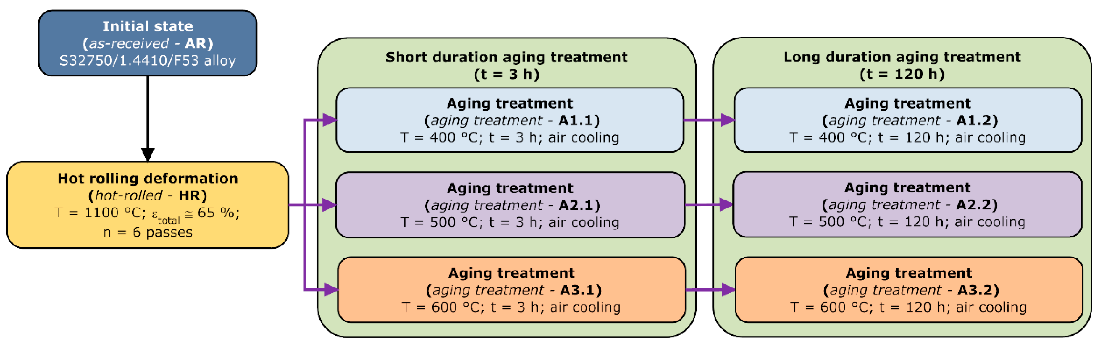
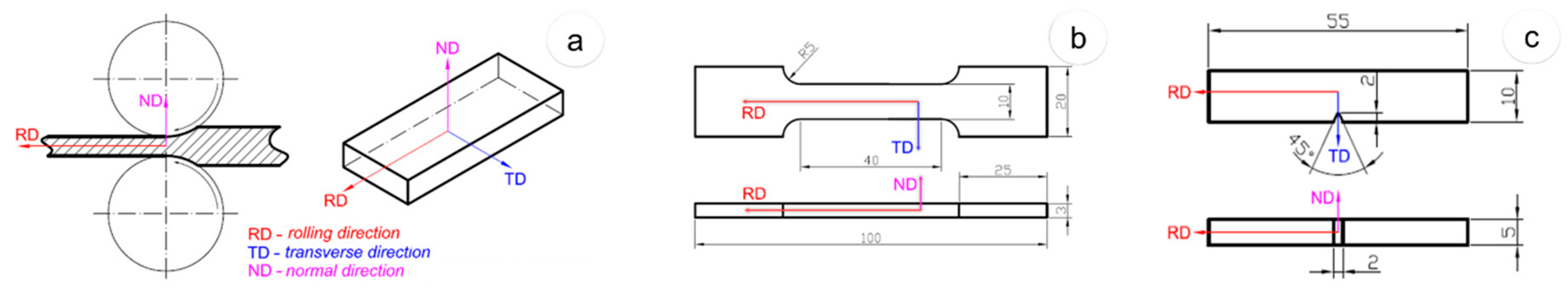
2. Materials and Methods

The investigated UNS S32750 super duplex stainless steel (SDSS) alloy was thermo-mechanically (TM) processed according to the processing route presented in Figure 1. The as-received (AR) UNS S32750 alloy was hot deformed by rolling (hot-rolled—HR), at a temperature of 1100 °C, using six rolling steps, up to a total deformation degree (thickness reduction) of approximately εtotal ≈ 65%. For each rolling step, a constant deformation degree (εpartial ≈ 11%) was used. After each rolling step, the rolled samples were re-heated up to the nominal deformation temperature (1100 °C) in order to perform the next rolling step.
After hot rolling, the samples were aged using different temperatures and durations. The first set of samples was subjected to short-duration aging treatments, at the following temperatures: 400 °C (aging treatment-A1.1), 500 °C (aging treatment-A2.1), and 600 °C (aging treatment-A3.1), with a duration of 3 h (180 min). The second set of samples was subjected to long-duration aging treatments, at the following temperatures: 400 °C (aging treatment-A1.2), 500 °C (aging treatment-A2.2), and 600 °C (aging treatment-A3.2), with a duration of 120 h (five days).
All TM processed specimens were investigated from the point of view of microstructural and mechanical properties. Considering the TM processing specific features, the samples´ reference frame, indicated in Figure 2a, assumes the following main directions: RD—rolling direction, TD—transverse direction, and ND—normal direction. The sample’s microstructure was analysed in the plane defined by the RD–ND directions, while all mechanical properties were analysed along the RD direction (Figure 2b).
The metallographic preparation procedure applied to all the samples collected from all TM processed states is presented and detailed elsewhere [19,20,21]. The microstructure was investigated by SEM techniques, with the purpose of observing the microstructural constituent phases and the changes occurred during TM processing. A SEM-TESCAN Vega II-XMU (TESCAN, Brno, Czech Republic) microscope was used to perform microstructural analysis. Microstructural constituent phases and changes occurred during TM processing were analysed using the SEM coupled with a BRUKER Quantax e-Flash EBSD detector. The following parameters were used: 250× magnification, 320 × 240 pixels resolution, 10 ms acquisition time/pixel, 1 × 1 binning size, and less than 3% zero solutions. During the SEM-EBSD analysis, the identified phases were indexed as follows: δ-phase indexed in body-centred cubic (BCC) system, with a lattice parameter of a = 2.86 Å; γ-phase indexed in face-centred cubic (FCC) system, with a lattice parameter of a = 3.66 Å; and R-phase (Fe(Cr)NiMo) indexed in the trigonal system, with a lattice parameter of a = 10.85 Å and c = 19.71 Å. No other secondary phases (i.e., χ-phase, σ-phase, nitrides, carbides) were detected during SEM-EBSD analysis.
All TM processed specimens were also tensile tested in order to determine the following mechanical properties: ultimate tensile strength (σUTS), 0.2 yield strength (σ0.2), and elongation to fracture (εf). For tensile testing, the dog-bone shaped samples were used (Figure 2b), with a calibrated section of 40 mm × 10 mm × 3 mm. Further, during testing, a 12.5 mm displacement extensometer was used. Tensile testing measurements were performed using an INSTRON 3382 (INSTRON, Norwood, MA, USA) universal testing equipment. Besides tensile testing, an impact Charpy testing was performed using V-notch 55 mm × 10 mm × 5 mm samples (Figure 2c). The Charpy testing measurements were performed using an INSTRON 450 MPX-v2-J1 (INSTRON, Norwood, MA, USA) testing equipment. In order to compute the average values for all investigated mechanical properties, the following procedure was applied: for each TM processed specimen, six arbitrary samples were tested in identical conditions; computed data were statistically analysed and the standard deviation was determined for each investigated mechanical property. All data were rounded to the nearest whole number, in MPa and J (for strength and impact properties), while the elongation was rounded to 0.5% (i.e., according to EN 10002-1).

3. Results

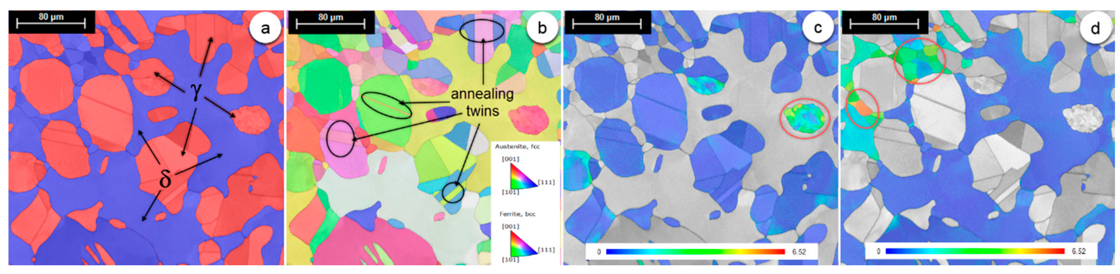
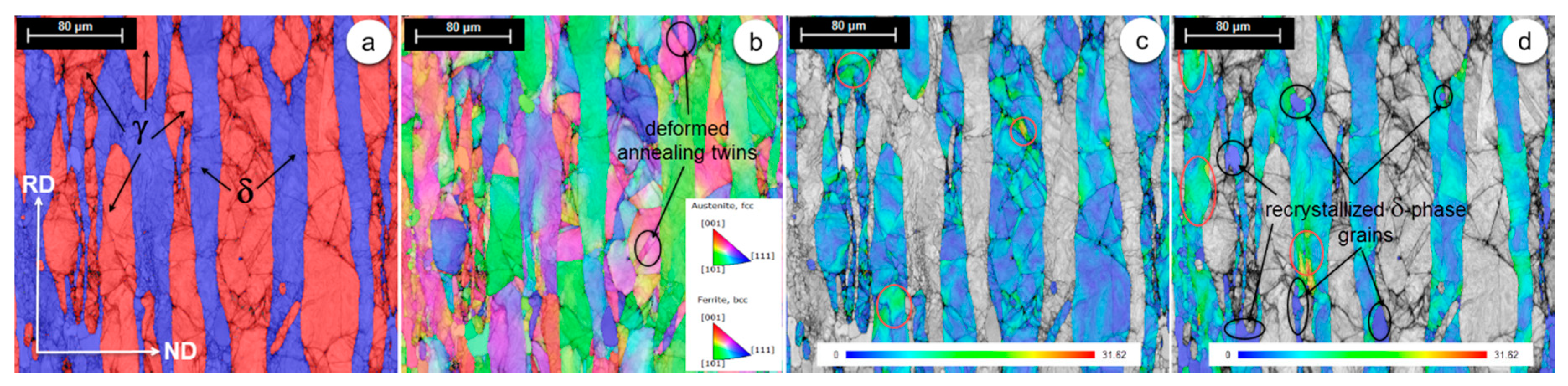
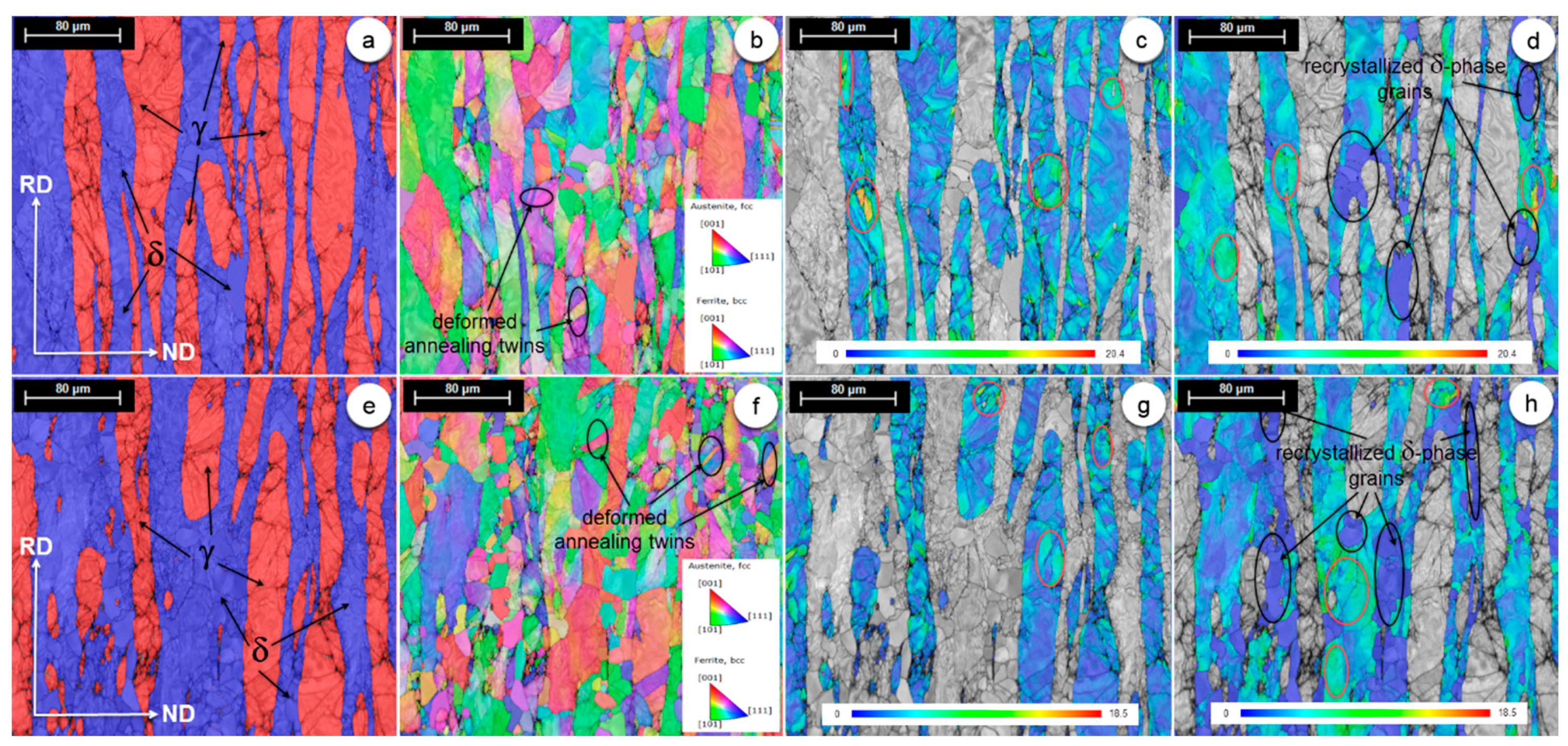
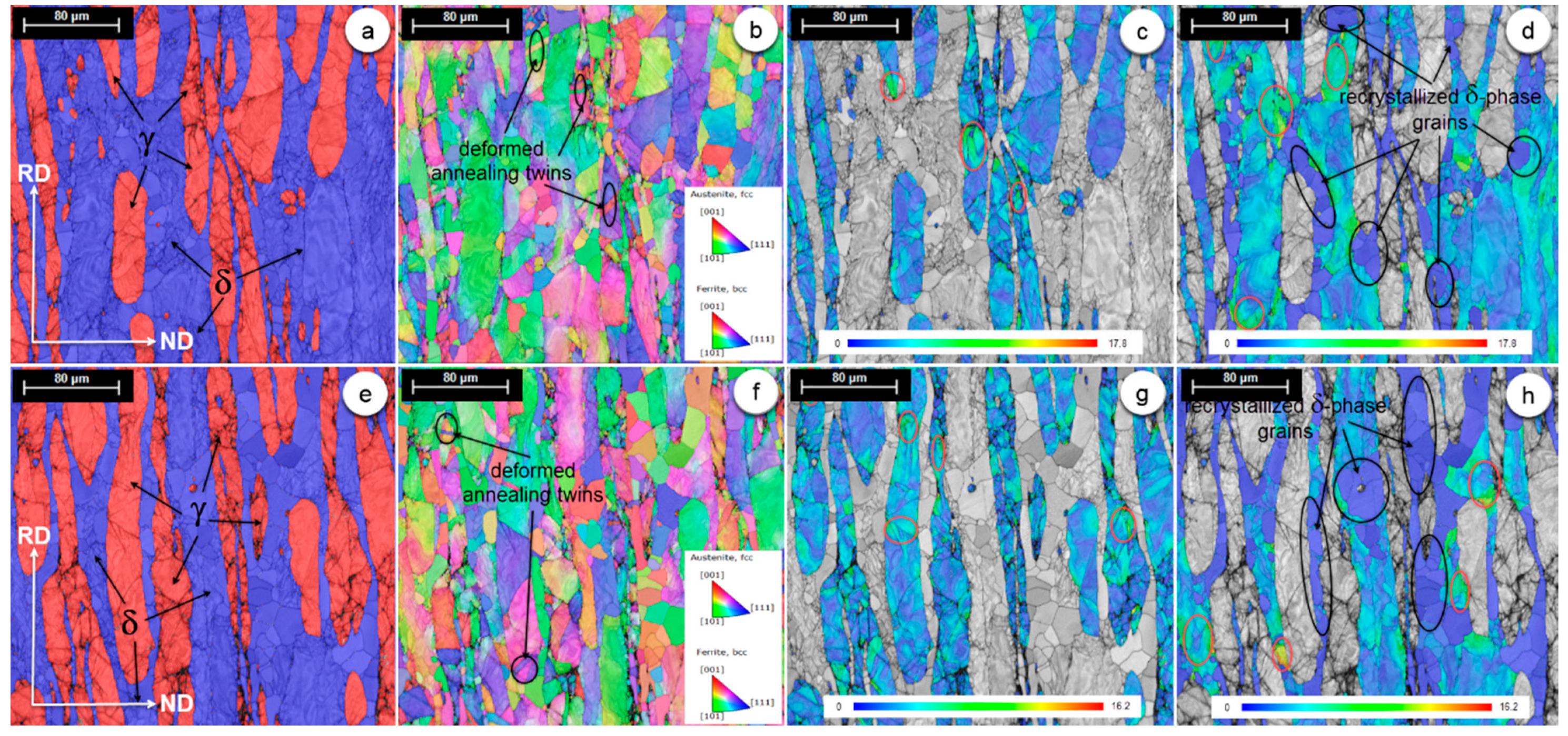
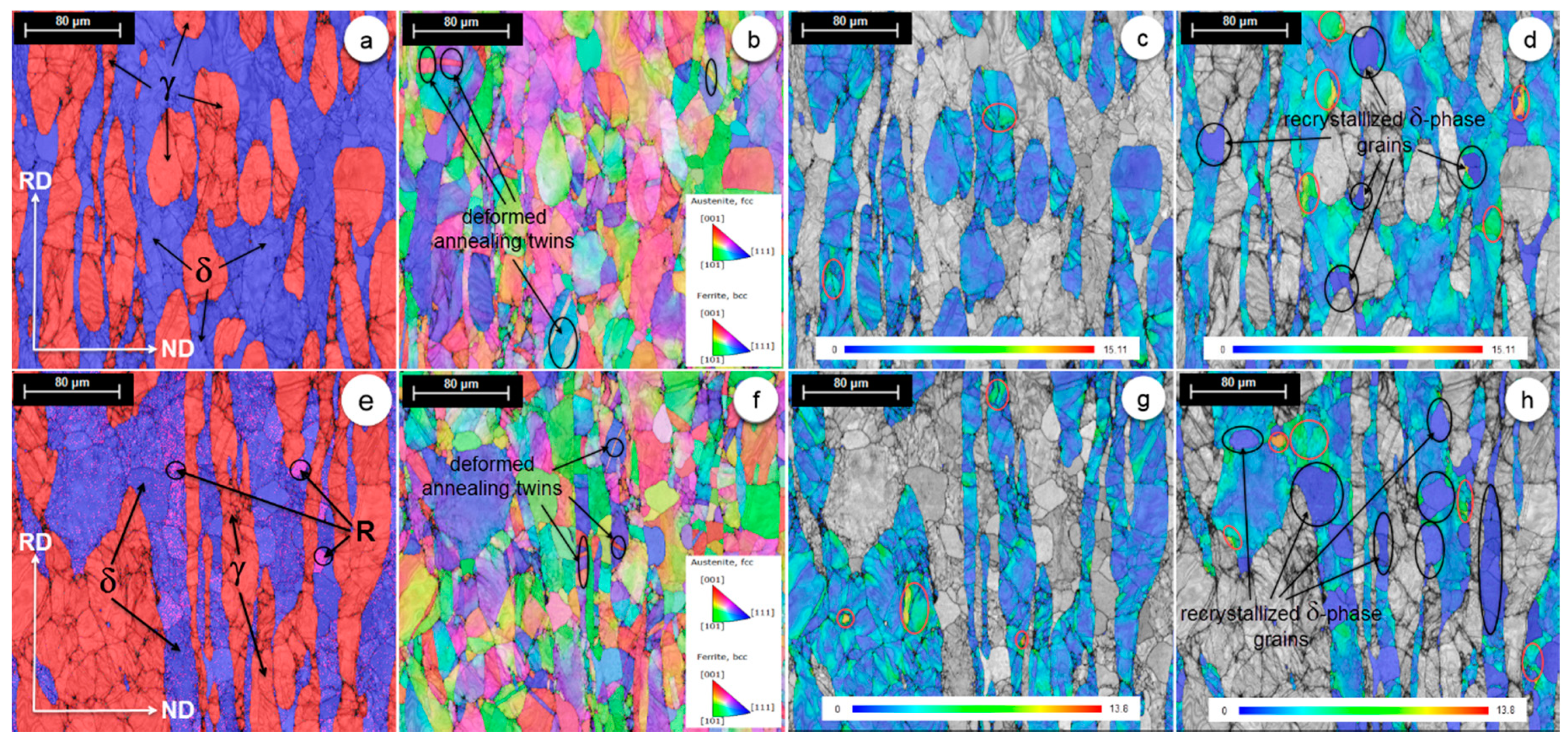
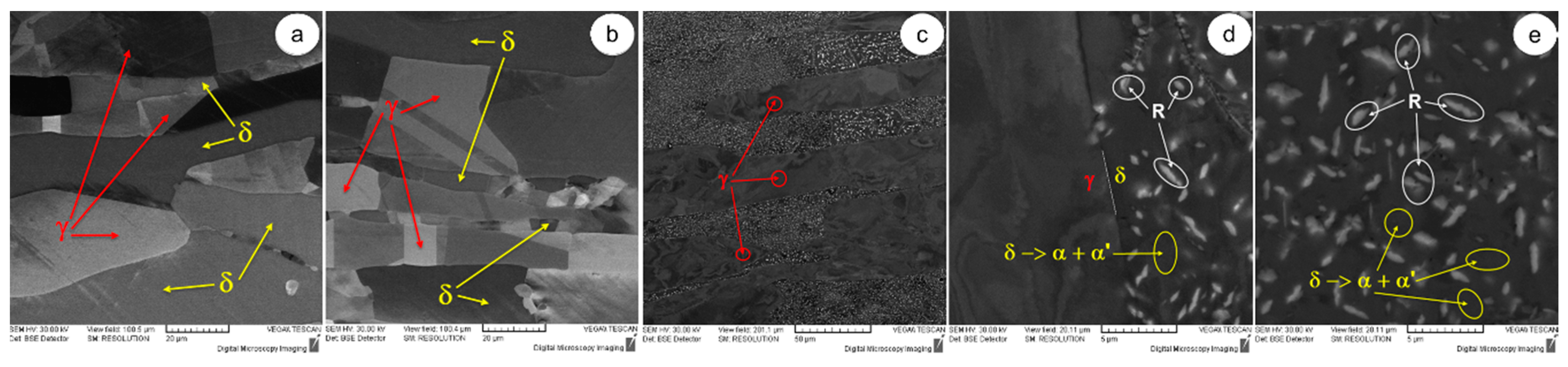
3.1. Microstructural Evolution During TM Processing of UNS S32750 SDSS Alloy

Figure 3a shows the SEM-EBSD image of phase map distribution for the UNS S32750 SDSS alloy in the as-received (AR) state. One can observe that the identified phases were as follows: δ-phase (coloured in blue) and γ-phase (coloured in red). One can also observe that the γ-phase presents an islands-like morphology within the δ-phase matrix. On the basis of SEM-EBSD analysis, the constituent phase ratio was computed. The computation algorithm assumed 10 measurements of 403.4 × 403.4 (μm × μm) fields and statistical analysis of obtained phase ratios. It was determined that the F53 SDSS alloy in AR condition showed the presence of 49.1% ± 2.3% δ-phase and 50.9% ± 2.1% γ-phase. Figure 3b shows the grains’ orientation distribution for both the δ-phase and γ-phase. A closer look at the γ-phase grains’ orientation distribution shows the presence of annealing twins. Similar observations were also made by other researchers, showing that the annealing twins belong to the {111} <112> system [22,23,24].
The grain reference orientation deviation (GROD) map can be used as a visualisation tool to assess the accumulated deformation/strain at microstructural level [25,26]. GROD is based on the misorientation (MO) between a reference point of that grain and the other points. The reference point can be the mean orientation of the grain or the point of the grain where the KAM (kernel average misorientation) is the lowest [27,28]. In the present work, the GROD map provides the orientation field referenced to a fixed point, which is the mean orientation of the grain. As shown, the GROD map shows grains exhibiting deviations from the average grain orientation, deviations due to accumulated strain resulting as a consequence of, firstly, grains’ deformations by slip/twinning and/or rotations and, secondly, other induced strain hardening effects during applied TM processing. Figure 3c,d show the GROD maps for the γ-phase and δ-phase, respectively. One can observe that the maximum MO reaches a value close to 6.52° and is recorded in the case of the δ-phase (Figure 3d). The γ-phase shows grains with a level of accumulated strain inferior to δ-phase, and in both phases, the maximum level of MO is recorded in small-size grains (Figure 3c,d).
Figure 4a shows the phase map distribution for the hot-rolled (HR) state. The microstructure consists of the δ-phase (coloured in blue) and γ-phase (coloured in red). It can be observed that the γ-phase shows a modified morphology, from an islands-like to a typical roll-deformed one, with high-elongated grains, along the RD direction, within the δ-phase matrix. Analysing the grains’ orientation distribution for both the δ-phase and γ-phase (Figure 4b), one can observe that the γ-phase grains accommodate better induced intense deformation, during the hot-deformation processing, when compared with the δ-phase grains and, furthermore, the observed annealing γ-phase twins show signs of deformation. Figure 4c,d show the GROD maps for the γ-phase and δ-phase, respectively. One can observe that the maximum MO reaches a value close to 31.62° (an increase of approximately 485%, compared with the AR state) and is recorded in the case of the δ-phase (Figure 4d). Besides intensely deformed grains, the δ-phase shows the presence of new dynamically recrystallized grains, which show uniform GROD distribution, with an average MO close to 0°, and an average grain-size close to 30 μm (Figure 4d). No new dynamically recrystallized grains were observed in the case of the γ-phase.
In all aging treatments states, short-duration aging treatments—A1.1, A2.1, and A3.1 states—and long-duration aging treatments—A1.2, A2.2, and A3.2 states—the observed morphology of both the δ-phase and γ-phase shows the same typical roll-deformed features, with highly-elongated, along the RD direction, γ-phase grains within the δ-phase matrix (Figure 5a,e, Figure 6a,e, Figure 7a,e). Only in the case of long-duration aging treatment A2.3, besides the δ-phase and γ-phase, a precipitated secondary phase was detected, namely the R-phase (Fe(Cr)NiMo) (Figure 7e), showing a fine and almost uniform distribution within the δ-phase matrix. The computed R-phase weight fraction, based on EBSD data, is situated close to 6.5%. In all cases, grains’ orientation distribution, for the δ-phase and γ-phase, shows that the γ-phase grains accommodate better the intense deformation compared with the δ-phase grains and the annealing γ-phase twins are still present (Figure 5b,f, Figure 6b,f, Figure 7b,f). Significant differences were observed in the case of GROD maps. One can see that the maximum GROD decreases continuously with the increasing aging treatment temperature and duration. In all cases, the maximum MO is recorded for the δ-phase. In the case of short-duration aging treatment states, the maximum MO continuously decreases to 20.40° for the A1.1 state (Figure 5d) (a decrease of approximately 35.5% compared with the HR state), to 17.80° for the A2.1 state (Figure 6d) (a decrease of approximately 43.7% compared with the HR state), and finally to 15.11° for the A3.1 state (Figure 7d) (a decrease of approximately 52.2% compared with the HR state). Analysing the case of long-duration aging treatment states, it can be observed that the GROD maps suffers further decreasing owing to increased treatment duration (120 h). Recorded maximum MO values are continuously decreasing, to 18.50° for the A1.2 state (Figure 5h) (a decrease of approximately 9.3% compared with the A1.1 state), to 16.20° for the A2.2 state (Figure 6h) (a decrease of approximately 8.9% compared with the A2.1 state), and finally to 13.8° for the A3.2 state (Figure 7h) (a decrease of approximately 8.6% compared with the A3.1 state). The observed decrease suggests that an important effect induced by the aging treatments is represented by the stress relieving phenomena within the microstructure. The main characteristics of stress relieving are represented by the removal of unwanted effects induced by plastic deformation. Owing to stress relieving, the crystal imperfections density and high elastic strains and residual stress fields can be significantly lowered, improving the material’s exhibited properties.
In both short-duration aging treatment and long-duration aging treatment states, one can observe the presence of new, dynamically recrystallized δ-phase grains. If one compares the observed number of recrystallized δ-phase grains in the case of HR (Figure 4d) with ones obtained after aging performed at 400 °C for 3 h (A1.1 state—Figure 5d) and 120 h (A1.2 state—Figure 5h), they will notice that the highest number of recrystallized δ-phase grains is observed in the case of the A1.2 state, followed by the A1.1 state, and finally the HR state, suggesting that the aging treatment duration influences the recrystallization of new δ-phase grains. Similar observations can also be made in the case of aging performed at 500 °C for 3 h (A2.1 state—Figure 6d) and 120 h (A2.2 state—Figure 6h), and in the case of aging performed at 600 °C for 3 h (A3.1 state—Figure 7d) and 120 h (A3.2 state—Figure 7h). Generally, an intensely deformed phase behaves better as the number of new recrystallized grains, from the parent phase, is increasing (i.e., if one considers δ-phase ductility, it is expected that a higher ductility will be obtained as the number of recrystallized grains is increasing).
The decrease in GROD and the increased number of recrystallized δ-phase grains are proving that aging treatments, at temperatures between 400 and 600 °C and durations between 3 and 120 h, can influence the properties exhibited by the UNS S32750 SDSS alloy.

3.2. Mechanical Properties Evolution During TM Processing of the UNS S32750 SDSS Alloy

Mechanical properties were determined based on the engineering strain–stress curves, obtained during tensile testing and Charpy impact testing for all TM processed samples. The following mechanical properties were considered: ultimate tensile strengthUTS), 0.2 yield strength0.2), elongation to fracturef) during tensile testing, and absorbed energy (E) during Charpy impact testing. The computed values of considered mechanical properties are presented in Table 1.
On the basis of the obtained results, one can observe that the highest value of ultimate tensile strength, close to 877 ± 13 MPa, is obtained in the case of aging treatment A3.3, and the lowest is recorded in the case of the as-received AR state, close to 720 ± 10 MPa. For 0.2 yield strength, the highest value, close to 641 ± 13 MPa, is obtained for the aging treatment A1.2, and the lowest is also recorded in the case of the as-received AR state, close to 473 ± 14 MPa. For the elongation to fracture, the highest value, close to 55.5% ± 4%, is recorded for the as-received (AR) state and the lowest, close to 32.5% ± 3%, in the case of aging treatment A2.2. The results obtained during impact testing showed that the highest absorbed energy, close to 103 ± 4 J, is recorded for the as-received (AR) and aging treatment A1.1, and the lowest, close to 9 ± 2 J, in the case of aging treatment A3.2. Analysing all data, one can observe that the material’s mechanical properties are strongly influenced by the applied aging treatments, especially the absorbed anergy during impact testing, showing a pronounced induced embrittlement.
Computed mechanical properties for all aging treatment states exceed the minimum values imposed by the UNS S32750 / AISI F53 / WS 1.4410 / ASTM A182 F53 / ASTM A276 F53 / ASTM A479 F53 standards (σUTS = min. 750 MPa; σ0.2 = min. 550 MPa; εf = min. 15%).

4. Discussion

Generally, in order to explain the recoded behaviour, the following mechanism should be considered. Firstly, one must consider the phase fractions’ influence, through the mixing law, stating that a higher fraction of a certain phase induces a higher influence on the overall material’s properties. Secondly, one must consider the specific mechanisms and phenomena occurring during material’s specified TM processing route.
Observations made in the case of microstructural analysis, for all TM processed states, concerning typical deformation morphologies for both the δ-phase (belonging to a BCC crystallographic system) and γ-phase (belonging to an FCC crystallographic system) are related to the higher potential of deformation/strain accommodation by slip/twinning and/or grain rotations of FCC systems, compared with BCC systems [29,30,31,32] for the same deformation stress level. For the same deformation stress level, if one considers the slip/twinning deformation mechanisms in correlation with the potential of deformation/strain accommodation, they will observe that the main influence factor is represented by the atomic density on the easiest to activate slip/twinning system [33,34]. In the case of FCC systems, the easiest to activate slip system is {111} <110>, while the easiest to activate twinning system is {111} <112>. In the case of BCC systems, the easiest to activate slip system is {110} <111>, while the easiest to activate twinning system is {112} <111> [29,30,31,32,35]. The highest atomic density, almost double, is exhibited by FCC {111} atomic planes, compared with the BCC {110} and {112} atomic planes, which shows that FCC systems better accommodate deformation/strain, by slip/twinning and/or grain rotations, compared with BCC systems, for the same deformation stress level. Considering these aspects, one can explain the observed higher potential of deformation/strain accommodation of the γ-phase compared with the δ-phase (lower GROD values are recorded for the γ-phase in comparison with the δ-phase for all cases). Besides slip/twinning, one must also consider the nucleation, displacement, and blocking of dislocations during deformation, which can lead to grains’ rotations in both the δ- and γ-phases and, activation of slip/twinning on less favourable systems (with a lower atomic density on slip/twinning plane).
Other phenomena occurring during the hot deformation (HR state) are represented by the dynamic recrystallization of new grains. Owing to the high deformation temperature, 1100 °C, besides the strain hardening phenomena (closely linked to increased dislocation density, new dislocations are continuously nucleated, by primary Frank–Read sources, and blocked at grain level, resulting in an increased dislocation density), the dynamic recrystallization of new grains can occur [36]. Analysing the HR state, it can be observed that typical morphologies of strain hardened microstructure are noticed for both the δ- and γ-phases (Figure 4c,d), while new dynamically recrystallized grains are observed only in the case of the δ-phase (Figure 4d). The small number and small-size of new dynamically recrystallized δ-phase grains resides in the short duration of hot-deformation processing at 1100 °C.
To explain the behaviour recorded in the case of short-duration aging treatments (A1.1, A2.1, and A3.1) and long-duration aging treatments (A1.2, A2.2, and A3.2), one must consider the following competitive phenomena: stress relieving and phase transformations, both occurring at temperatures below 600 °C.
By plastic deformation, a high density of crystal imperfections, such as dislocations, are induced within the material’s microstructure. Besides these, high elastic strains and residual stress fields are induced too. If the magnitude of these unwanted effects is high, these effects may cause worsening of different exhibited properties, such as mechanical properties and stress corrosion cracking resistance [37]. One important phenomenon occurring during a thermal treatment, performed after deformation, is represented by the residual stress relieving. The main influence parameters of stress relieving are represented by the treatment temperature and treatment duration. Generally, the stress relieving treatment is performed at a temperature bellow the annealing temperature, for not starting the recrystallization phenomena. The stress relieving temperature must be kept low, but the treatment time must be long enough to achieve the release of residual strains and stresses, and also to reduce the crystal imperfections’ density. Actually, a lower stress relieving temperature (at which excessive crystal imperfections are eliminated) can induce an improvement in mechanical properties, such as hardness, ultimate tensile strength, yield strength, elongation to fracture, and absorbed energy during impact testing.
In the case of duplex stainless steels, during isothermal heating, at temperatures below 600 °C, few phase transformation mechanisms can occur [16,17,18,19], with the most important one being spinodal decomposition of the δ-phase into coherent α-phase (Fe-enriched) and α’-phase (Cr-enriched), leading to the following important changes in alloy’s exhibited mechanical properties: a high decrease of toughness, an increase in hardness, a small decrease in elongation to fracture, and little or no changes in ultimate tensile strength and yield strength [38]. Other important transformation mechanisms that can occur are represented by the precipitation of secondary phases, such as the R-phase, G-phase, and chromium nitrides [12,13,14,15].
Figure 8 shows a comparative analysis of mechanical properties (ultimate tensile strength—Figure 8a, yield strength—Figure 8b, elongation to fracture—Figure 8c, and absorbed energy—Figure 8d) for the hot-rolled (HR) and short-duration aging treatments A1.1, A2.1, and A3.1. In the case of ultimate tensile strength (Figure 8a) and yield strength (Figure 8b), as shown, minimal changes are induced by short-duration aging treatments. Significant changes are observed in the case of elongation to fracture (Figure 8c) and absorbed energy (Figure 8d), with the elongation to fracture showing an increase with the increasing aging treatment temperature, from 400 °C to 600 °C, while the absorbed energy shows a decrease with the increasing aging treatment temperature.
This behaviour suggests that both competitive mechanisms, stress relieving and phase transformations, induced significant changes within the microstructure. A continuous increase of aging treatment temperature, from 400 °C to 600 °C for 3 h, induces a higher atom’s mobility within both the δ- and γ-phases, resulting in a continuous decrease in crystal imperfections’ density and lowered elastic strains and residual stress fields, which leads to significant increases in material’s ductility and strength properties [14,18]. The phase transformations occurring from 400 °C to 600 °C, such as the R-phase, G-phase, and chromium nitrides, can also drastically influence the exhibited properties by inducing embrittlement, decreasing toughness, strength properties, and increasing hardness [12,13,14,15]. One transformation that must be considered is represented by the spinodal decomposition δ → α (Fe-enriched) + α’ (Cr-enriched), which can start at temperatures as low as 280 °C [39,40,41]. Completion of spinodal decomposition, within the δ-phase matrix, takes a very long time owing to the low atomic mobility, even at temperatures up to 600 °C [9]. One must consider that, during spinodal decomposition, both α + α’ phases have nanometric grain-size and the same crystal lattice type, with minimal differences in lattice parameters, but with different compositions and thus properties [1]. The embrittlement induced by the spinodal decomposition δ → α + α’ plays a minor role in the material’s overall properties, owing to the very long time necessary for spinodal decomposition completion [9,42]. Considering the used microstructural investigation techniques (SEM-EBSD), no other secondary phases were observed.
Overall, increasing the treatment temperature increases the influence of stress relieving on the material’s ductility, and also increases the volume fraction of nanometre-size precipitated secondary phases, which induces important embrittlement.
Figure 9 shows a comparative analysis of mechanical properties (ultimate tensile strength—Figure 9a, yield strength—Figure 9b, elongation to fracture—Figure 9c, and absorbed energy—Figure 9d) for the hot-rolled (HR) and long-duration aging treatments A1.2, A2.2, and A3.2. In the case of ultimate tensile strength (Figure 9a), yield strength (Figure 9b), and elongation to fracture (Figure 9c), as shown, minimal changes are induced by long-duration aging treatments. Significant changes are observed in the case of absorbed energy (Figure 9d), where increasing aging treatment temperature, from 400 °C to 600 °C, leads to a sharp decrease in the absorbed energy during impact testing.
The observed embrittlement must be explained considering the higher volume fraction of precipitated secondary phases. Considering a treatment duration of 120 h, the volume fraction of spinodal decomposition δ → α + α’ must be high enough to induce pronounced embrittlement effects. It was reported, in the case of the SAF 2507 (a UNS S32750 equivalent) SDSS alloy, that, at treatment durations exceeding 10 h, the volume fraction of spinodal decomposition δ → α + α’ is significant and the induced embrittlement must be considered [1], and the highest volume fraction of spinodal decomposition δ → α + α’ was obtained for aging temperatures close to 475 °C for the same treatment durations [1]. At 600 °C, besides spinodal decomposition, one must consider the embrittlement effect induced by precipitation of the R-phase. Considering the cumulative effect of spinodal decomposition and precipitation of the R-phase, one can explain the obtained minimum absorbed energy during impact testing for long-duration aging treatment A3.2 (600 °C; 120 h).
In order to observe the secondary phases precipitates, besides SEM-EBSD, the SEM-BSE analysis was also performed. In the case of long-duration aging treatments A1.2 (Figure 10a) and A2.2 (Figure 10b), no precipitates of secondary phases were observed. Only in the case of long-duration aging treatment A3.2 (Figure 10c), precipitates of secondary phases were observed. Considering previous observations [12,13,14,15] and data obtained from SEM-EBSD analysis (Figure 7e), one can assume that the observed phase is the R-phase.
The morphology of precipitated R-phase (Figure 10c–e) shows a very fine and uniform distribution, withing the δ-phase matrix, with an elongated grain morphology. The average grain-size of R-phase was situated close to 1 μm (Figure 10d,e). Besides the R-phase, within the δ-phase matrix, traces of spinodal decomposition δ -> α (Fe-enriched-dark grey) + α’ (Cr-enriched-light grey) can also be seen (Figure 10d,e). Both α (Fe-enriched) and α’ (Cr-enriched) phases can be detected through more complex investigation techniques (i.e., high-resolution transmission electron microscopy (HR-TEM), atom probe field ion microscopy (AP-FIM)) [43,44], owing to their nanometer-size dimension.

5. Conclusions

The influence of aging treatments on the microstructure and tensile properties of a hot deformed UNS S32750 super duplex stainless steel (SDSS) alloy can be summarized as follows:
  • the main positive effect of isothermal aging treatment is represented by the possibility to control the exhibited mechanical properties of the TM processed alloy;
  • the average grain-size and number of dynamically recrystallized new δ-phase grains can be controlled by varying the isothermal aging treatment temperature and duration;
  • during the short-duration aging treatment, at temperatures between 400 °C and 600 °C, the most influential occurring phenomena is represented by the stress relieving;
  • during the long-duration aging treatment, at temperatures between 400 °C and 600 °C, the most influential occurring phenomena are represented by the secondary phase precipitation, with a strong influence on material’s embrittlement.
Further optimization of the aging processing route, in order to achieve a favourable balance between plastic, strength, and toughness properties in the UNS S32750 Super Duplex Stainless Steel (SDSS) alloy is currently being undertaken by the present authors.

Author Contributions

E.M.C., D.R., and V.D.C. conceived and designed the experiments; E.M.C., N.S., M.L.A., I.C., and V.D.C. performed the experiments; E.M.C., D.R, A.N., N.S., M.L.A., I.C., A.N.V., and V.D.C. analysed the data; A.N.V. contributed reagents/materials/analysis tools; E.M.C. and A.N. wrote—reviewed and edited the paper. All authors have read and agreed to the published version of the manuscript.

Funding

This research received no external funding.

Conflicts of Interest

The authors declare no conflict of interest. The founding sponsors had no role in the design of the study; in the collection, analyses, or interpretation of data; in the writing of the manuscript; and in the decision to publish the results.

References

  1. Nilsson, J.O. Super duplex stainless steels. J. Mater. Sci. Technol. 1992, 8, 685–700. [Google Scholar] [CrossRef]
  2. Weisbrodt-Reisch, A.; Brummer, M.; Hadler, B.; Wolbank, B.; Werner, E.A. Influence of temperature, cold deformation and a constant mechanical load on the microstructural stability of a nitrogen alloyed duplex stainless steel. Mater. Sci. Eng. A 2006, 416, 1–10. [Google Scholar] [CrossRef]
  3. Bhadeshia, H.K.D.H.; Honeycombe, R. 12 - Stainless Steel. In Steels - Microstructure and Properties, 3rd ed.; Butterworth-Heinemann: Oxford, UK, 2006; pp. 259–286. [Google Scholar]
  4. Luo, H.; Dong, C.F.; Xiao, K.; Li, X.G. Characterization of passive film on 2205 duplex stainless steel in sodium thiosulphate solution. Appl. Surf. Sci. 2011, 258, 631–639. [Google Scholar] [CrossRef]
  5. Xiong, J.; Tan, M.Y.; Forsyth, M. The corrosion behaviors of stainless steel weldments in sodium chloride solution observed using a novel electrochemical measurement approach. Desalination 2013, 327, 39–45. [Google Scholar] [CrossRef]
  6. Yousefieh, M.; Shamanian, M.; Saatchi, A. Optimization of the pulsed current gas tungsten arc welding (PCGTAW) parameters for corrosion resistance of super duplex stainless steel (UNS S32760) welds using the Taguchi method. J. Alloys Compd. 2011, 509, 782–788. [Google Scholar] [CrossRef]
  7. Tavares, S.S.M.; Silva, V.G.; Pardal, J.M.; Corte, J.S. Investigation of stress corrosion cracks in a UNS S32750 superduplex stainless steel. Eng. Fail. Anal. 2013, 35, 88–94. [Google Scholar] [CrossRef]
  8. Zanotto, F.; Grassi, V.; Balbo, A.; Monticelli, C.; Zucchi, F. Stress corrosion cracking of LDX 2101 duplex stainless steel in chloride solutions in the presence of thiosulphate. Corros. Sci. 2014, 80, 205–212. [Google Scholar] [CrossRef]
  9. Hattestrand, M.; Larsson, P.; Chai, G.; Nilsson, J.O.; Odqvist, J. Study of decomposition of ferrite in a duplex stainless steel cold worked and aged at 450–500 °C. Mater. Sci. Eng. A 2009, 499, 489–492. [Google Scholar] [CrossRef]
  10. Li, S.; Wang, Y.; Li, S.; Zhang, H.; Xue, F.; Wang, X. Microstructures and mechanical properties of cast austenite stainless steels after long-term thermal aging at low temperature. Mater. Des. 2013, 50, 886–892. [Google Scholar] [CrossRef]
  11. Argandona, G.; Palacio, J.F.; Berlanga, C.; Biezma, M.V.; Rivero, P.J.; Pena, J.; Rodriguez, R. Effect of the temperature in the mechanical properties of austenite, ferrite and sigma phases of duplex stainless steels using hardness, microhardness and nanoindentation techniques. Metals 2017, 7, 219. [Google Scholar] [CrossRef] [Green Version]
  12. Southwick, P.D.; Honeycombe, R.W.K. Precipitation of M23C6 at austenite/ferrite interfaces in duplex stainless steel. Met. Sci. 1982, 16, 475–482. [Google Scholar] [CrossRef]
  13. Unnikrishnan, K.; Mallik, A.K. Aging behaviour of a duplex stainless steel. Mater. Sci. Eng. A 1987, 95, 259–265. [Google Scholar] [CrossRef]
  14. Duprez, L.; Cooman, B.D.; Akdut, N. Microstructure evolution during isothermal annealing of a standard duplex stainless steel type 1.4462. Steel Res. 2000, 71, 417–422. [Google Scholar] [CrossRef]
  15. Nowacki, J.; Lukojc, A. Microstructural transformations of heat affected zones in duplex steel welded joints. Mater. Charact. 2006, 56, 436–441. [Google Scholar] [CrossRef]
  16. Pohl, M.; Storz, O.; Glogowski, T. Effect of intermetallic precipitations on the properties of duplex stainless steel. Mater. Charact. 2007, 58, 65–71. [Google Scholar] [CrossRef]
  17. Maetz, J.Y.; Cazottes, S.; Verdu, C.; Kleber, X. Precipitation and phase transformations in 2101 lean duplex stainless steel during isothermal aging. Metall. Mater. Trans. A 2016, 47, 239–253. [Google Scholar] [CrossRef]
  18. Armas, A.F.; Herenu, S.; Alvarez-Armas, I.; Degallaix, S.; Condo, A.; Lovey, F. The influence of temperature on the cyclic behavior of aged and unaged super duplex stainless steels. Mater. Sci. Eng. A 2008, 491, 434–439. [Google Scholar] [CrossRef]
  19. Cojocaru, V.D.; Serban, N.; Angelescu, M.L.; Cotrut, M.C.; Cojocaru, E.M.; Vintila, A.N. Influence of solution treatment temperature on microstructural properties of an industrially forged UNS S32750/1.4410/F53 super duplex stainless steel (SDSS) alloy. Metals 2017, 7, 210. [Google Scholar] [CrossRef] [Green Version]
  20. Angelescu, M.L.; Cojocaru, V.D.; Serban, N.; Cojocaru, E.M. Evaluation of optimal forging temperature range for an industrial UNS S32750 SDSS alloy using SEM-EBSD analysis. Metals 2018, 8, 496. [Google Scholar] [CrossRef] [Green Version]
  21. Cojocaru, V.D.; Raducanu, D.; Angelescu, M.L.; Vintila, A.N.; Serban, N.; Dan, I.; Cojocaru, E.M.; Cinca, I. Influence of solution treatment duration on microstructural features of an industrial forged UNS S32750/1.4410/F53 super duplex stainless steel (SDSS) alloy. JOM 2017, 69, 1439–1445. [Google Scholar] [CrossRef]
  22. Grube, W.L.; Rouze, S.R. The origin, growth and annihilation of annealing twins in austenite. Can. Metall. Q. 1963, 2, 31–52. [Google Scholar] [CrossRef]
  23. Gleiter, H. The formation of annealing twins (Formation des macles de recuit/Die bildung von anaβzwillingen). Acta Metall. 1969, 17, 1421–1428. [Google Scholar]
  24. Mahajan, S.; Pande, C.S.; Imam, M.A.; Rath, B.B. Formation of annealing twins in f.c.c. crystals. Acta Mater. 1997, 45, 2633–2638. [Google Scholar] [CrossRef]
  25. Schayes, C.; Bouquerel, J.; Vogt, J.B.; Palleschi, F.; Zaefferer, S. A comparison of EBSD based strain indicators for the study of Fe-3Si steel subjected to cyclic loading. Mater. Charact. 2016, 115, 61–70. [Google Scholar] [CrossRef]
  26. Kamaya, M. Characterization of microstructural damage due to low-cycle-fatigue by EBSD observation. Mater. Charact. 2009, 160, 1454–1462. [Google Scholar] [CrossRef]
  27. Wright, S.I.; Nowell, M.M.; Field, D.P. A review of strain analysis using electron backscatter diffraction. Microsc. Microanal. 2011, 17, 316–329. [Google Scholar] [CrossRef]
  28. Kamaya, M. Assessment of local deformation using EBSD: Quantification of local damage at grain boundaries. Mater. Charact. 2012, 66, 56–67. [Google Scholar] [CrossRef]
  29. Christian, J.W.; Mahajan, S. Deformation twinning. Prog. Mater. Sci. 1995, 39, 1–157. [Google Scholar] [CrossRef]
  30. Liang, Z.Y.; Huang, M.X. Deformation twinning in small-sized face-centred cubic single crystals: Experiments and modelling. J. Mech. Phys. Solids 2015, 85, 128–142. [Google Scholar] [CrossRef]
  31. Chen, Z.; Cai, H.; Li, S.; Zhang, X.; Wang, F.; Tan, C. Analysis of crystallographic twinning and slip in fcc crystals under plane strain compression. Mater. Sci. Eng. A 2007, 464, 101–109. [Google Scholar] [CrossRef]
  32. Li, N.; Wang, J.; Misra, A.; Zhang, X.; Huang, J.Y.; Hirth, J.P. Twinning dislocation multiplication at a coherent twin boundary. Acta Mater. 2011, 59, 5989–5996. [Google Scholar] [CrossRef]
  33. Marinelli, M.C.; El-Bartali, A.; Signorelli, J.W.; Evrard, P.; Aubin, V.; Alvarez-Armas, I.; Degallaix-Moreuil, S. Activated slip systems and microcrack path in LCF of a duplex stainless steel. Mater. Sci. Eng. A 2009, 509, 81–88. [Google Scholar] [CrossRef]
  34. Smida, T.; Bosansky, J. Deformation twinning and its possible influence on the ductile brittle transition temperature of ferritic steels. Mater. Sci. Eng. A 2000, 287, 107–115. [Google Scholar] [CrossRef]
  35. Wang, Y.Y.; Sun, X.; Wang, Y.D.; Hu, X.H.; Zbib, H.M. A mechanism-based model for deformation twinning in polycrystalline FCC steel. Mater. Sci. Eng. A 2014, 607, 206–218. [Google Scholar] [CrossRef]
  36. Sun, Z.Q.; Yang, W.Y.; Qi, J.J.; Hu, A.M. Deformation enhanced transformation and dynamic recrystallization of ferrite in a low carbon steel during multipass hot deformation. Mater. Sci. Eng. A 2002, 334, 201–206. [Google Scholar] [CrossRef]
  37. Rys, J.; Cempura, G. Microstructure and deformation behavior of metastable duplex stainless steel at high rolling reductions. Mater. Sci. Eng. A 2017, 700, 656–666. [Google Scholar] [CrossRef]
  38. Wang, Y.; Yao, Y.H.; Wang, Z.P.; Jin, Y.H.; Zhang, X.L.; Liu, J.N. Thermal ageing on the deformation and fracture mechanisms of a duplex stainless steel by quasi in-situ tensile test under OM and SEM. Mater. Sci. Eng. A 2016, 666, 184–190. [Google Scholar] [CrossRef]
  39. Williams, R.O. Further studies of the iron-chromium system. Trans. TMS-AIME. 1958, 212, 497–502. [Google Scholar]
  40. Vintaikin, E.Z.; Loshmanov, A.A. Brittlness of 475 C. Iron-chromium alloys. Fiz. Metallov Metalloved. 1966, 22, 473–476. [Google Scholar]
  41. Pettersson, N.; Wessman, S.; Thuvander, M.; Hedstrom, P.; Odqvist, J.; Pettersson, R.F.A.; Hertzman, S. Nanostructure evolution and mechanical property changes during aging of a super duplex stainless steel at 300 °C. Mater. Sci. Eng. A 2015, 647, 241–248. [Google Scholar] [CrossRef]
  42. Sahu, J.K.; Krupp, U.; Ghosh, R.N.; Christ, H.J. Effect of 475 °C embrittlement on the mechanical properties of duplex stainless steel. Mater. Sci. Eng. A 2009, 508, 1–14. [Google Scholar] [CrossRef]
  43. Auger, P.; Danoix, F.; Menand, A.; Bonnet, S.; Bourgoin, J.; Guttmann, M. Atom probe and transmission electron microscopy study of aging of cast duplex stainless steels. Mater. Sci. Technol. 1990, 6, 301–313. [Google Scholar] [CrossRef]
  44. Johansson, J.; Odeon, M. Load sharing between austenite and ferrite in a duplex stainless steel during cyclic loading. Metall. Mater. Trans. A 2000, 36, 1557–1570. [Google Scholar] [CrossRef]
Figure 1. Schematic representation of the applied thermomechanical processing route.
Metals 10 00353 g001
Figure 2. Samples reference system (a), geometrical configuration for tensile testing (b), and Charpy testing specimens (c).
Metals 10 00353 g002
Figure 3. Distribution map of the γ- and δ-phases (a), inverse pole figure (IPF) (b), grain reference orientation deviation (GROD) map of γ-phase (c) and δ-phase (d) for the as-received (AR) state.
Metals 10 00353 g003
Figure 4. Distribution maps of both the γ- and δ-phases (a), inverse pole figure (IPF) (b), GROD map of the γ-phase (c) and δ-phase (d) for the hot-rolled (HR) state.
Metals 10 00353 g004
Figure 5. Distribution maps of both the γ- and δ-phases (a), inverse pole figure (IPF) (b), GROD map of the γ-phase (c) and δ-phase (d) for the short-duration aging treatment (A1.1) state; distribution maps of both the γ- and δ-phases (e), inverse pole figure (IPF) (f), GROD map of the γ-phase (g) and δ-phase (h) for the long-duration aging treatment (A1.2) state.
Metals 10 00353 g005
Figure 6. Distribution maps of both the γ- and δ-phases (a), inverse pole figure (IPF) (b), GROD map of the γ-phase (c) and δ-phase (d) for the short-duration aging treatment (A2.1) state; distribution maps of both the γ- and δ-phases (e), inverse pole figure (IPF) (f), GROD map of the γ-phase (g) and δ-phase (h) for the long-duration aging treatment (A2.2) state.
Metals 10 00353 g006
Figure 7. Distribution maps of both the γ- and δ-phases (a), inverse pole figure (IPF) (b), GROD map of the γ-phase (c) and δ-phase (d) for the short-duration aging treatment (A3.1) state; distribution maps of both the γ- and δ-phases (e), inverse pole figure (IPF) (f), GROD map of the γ-phase (g) and δ-phase (h) for the long-duration aging treatment (A3.2) state.
Metals 10 00353 g007
Figure 8. Comparative representation of mechanical properties for the hot-rolled (HR) and short-duration aging treatments A1.1, A2.1, and A3.1 states for ultimate tensile strength (a), yield strength (b), elongation to fracture (c), and absorbed energy (d).
Metals 10 00353 g008
Figure 9. Comparative representation of mechanical properties for the hot-rolled (HR) and long-duration aging treatments A1.2, A2.2, and A3.2 states for ultimate tensile strength (a), yield strength (b), elongation to fracture (c), and absorbed energy (d).
Metals 10 00353 g009
Figure 10. Scanning electron microscopy (SEM)-BSE images of long-duration aging treatment A1.2 (a), A2.2 (b), and A3.2 (c); high-magnification SEM-BSE images of A3.2 (d) and (e).
Metals 10 00353 g010
Table 1. Mechanical properties for the thermomechanical (TM) processed UNS S32750 super duplex stainless steel (SDSS) alloy.
Structural StateMechanical Properties
Ultimate Tensile Strength, σUTS [MPa]0.2 Yield Strength, σ0.2 [MPa]Elongation to Fracture, εf [%]Absorbed Energy, E [J]
As-received (AR)720 ± 10473 ± 1455.5 ± 4.0103 ± 4
Hot-rolled (HR): T = 1100 °C; ε = 65%775 ± 14601 ± 1136.5 ± 2.590 ± 3
Aged (A1.1): T = 400 °C; t = 3 h769 ± 12595 ± 1333.0 ± 5.5103 ± 4
Aged (A1.2): T = 400 °C; t = 120 h863 ± 14641 ± 1342.0 ± 2.539 ± 3
Aged (A2.1): T = 500 °C; t = 3 h833 ± 12610 ± 1144.5 ± 4.596 ± 3
Aged (A2.2): T = 500 °C; t = 120 h814 ± 11624 ± 1132.5 ± 3.038 ± 3
Aged (A3.1): T = 600 °C; t = 3 h813 ± 14598 ± 1547.0 ± 3.551 ± 2
Aged (A3.2): T = 600 °C; t = 120 h877 ± 13599 ± 1439.0 ± 3.59 ± 2

