1. Introduction
One of the main motivations for the exponential increase in the use of composite materials, especially in transport structures such as airplanes, ships, and automobiles, is their excellent ratio between mechanical performance and weight. Any weight reduction in these structures directly relates to the reduction of energy consumption of the transportation mode. The other main advantage of composites is that they offer to adapt the material properties, and its internal micro-structure, to the strength requirements of the structure in which they are used. An example of this specific composite customization is found in the development of 3-Dimensional Laminate (3DL) sails for the yacht industry [
1] in which the different composite fibres are placed individually in the sail to obtain optimal performance.
Several factors allow for having highly efficient composites such as the aforementioned 3DL sails. One of them is the development of manufacturing techniques, such as it is Automatic Fibre Placement (AFP) [
2], that allows allocating, with extreme precision, a single fibre filament in the structural component. Another factor that has been key for the development of these new composites is the numerical formulations and tools required to predict the structural performance that will be obtained with such composites. As composites have become more complex, these tools have to be improved to account for the new material configurations. Therefore, in most cases, it is not sufficient to evaluate the composite as an orthotropic material and to apply a failure threshold criterion such as the ones reported in [
3]. Instead, it is necessary to use more complex formulations that obtain the composite performance by means of its constituent materials. One of these approaches is the serial-parallel mixing theory (S/P RoM) [
4], which acts as a constitutive equation manager and is based on the definition of a set of compatibility equations between the composite components, usually fibre and matrix, relating their stress-strain performance. The validity of the S/P RoM to accurately characterize the composite stiffness, as well as different composite failure modes, has already been demonstrated in several references [
5,
6,
7,
8].
However, when the composite architecture becomes more complex, for instance when having woven laminates, the serial/parallel mixing theory is not enough to account for all the micro-structural interactions between the composite constituents, being necessary the use of more complex formulations. Good candidates for such purposes are numerical multiscale procedures [
9,
10], which are based on solving the structural problem at hand by splitting it into two different scales. Namely, a macro-scale that discretizes the global problem, and a micro-scale that defines the material micro-structure. With this approach, the macro-scale deformation gradient tensor is used for the solution of the micro-scale problem, and then, using the microscopic results, for the obtainment of the macro-scale stress tensor. The microscopic problem is solved on a Representative Volume Element (RVE) model, which must be periodic and representative of the material [
11]. This approach is of special relevance for the analysis of woven composites, which micro-structural performance cannot be properly captured by the serial-parallel mixing theory. Examples of multiscale analysis on woven composites can be found in [
12,
13]
The vast number of possibilities that offer composite materials, regarding their internal configuration and their disposition in the structure, represents also a challenge to obtain the optimal configuration for a given structural application. One of the most common solutions used to customize the composite for a given application is by giving a preferred orientation to the composite laminate, which is done by placing more fibres in a given direction compared to the other ones. The definition of the optimal direction can be done based on a deep understanding of the structural performance of the element considered or, as it is done with more recent technologies, by coupling the structural analysis with an optimization procedure. In this regard, Nikbakt et al. [
14] have made an exhaustive review of the work that has been conducted by the scientific community regarding composite optimization. In their review they divide the work into the different types of structures analysed: beams, plates, shells, and other types; and, for each one of them, they provide the optimizations made based on the different objective functions considered, i.e., weight minimization or buckling load maximization. In their work, they realized that most of the analyses made are based on finding the best stacking sequence to obtain the desired structure performance. Examples of these types of analyses can be found in the work conducted by Ehsani and Rezaeepazhand [
15], Wei et al. [
16], and Zhou et al. [
17]. In the last work mentioned, the authors not only provide the optimal composite orientation, but they also find the best structural topology to handle the applied loads.
Optimization procedures are based on the modification of different structural parameters to obtain the desired structural performance, which is represented by an objective function. There are also optimization strategies that seek to obtain the improved performance of different objective functions. This is, for instance, maximizing the structure stiffness while minimizing its weight. Those are the so-called multi-objective optimization procedures [
18]. Several authors have already applied multi-objective optimization strategies to obtain the best composite configuration and, therefore, take maximum advantage of the multiple configuration capabilities of composite materials. Recent examples of this approach can be found in [
19,
20]. In these analyses, since they are based on a multi-objective optimization, the outcome is a Pareto Front, which provides the solutions showing an equilibrium of the optimized functions. The points on the Pareto Front are those which dominates the other solutions, which means that no solution improves the dominant ones without getting one of the objective function worse. A further step has been done in the works of Li et al. [
21] and Coelho et al. [
22,
23] in which the optimization method is applied to a multiscale procedure for the characterization of the composite structures. In the last one of these works, the parameters that can be modified to obtain the optimized structure performance are at the macro-level by modifying the fibre orientation, and at the micro-level by changing the volumetric participation of the different components in the composite. Other examples of multi-scale optimization can be found on references [
24,
25,
26,
27,
28,
29], which focus on topological optimization. In [
26,
27,
28], the authors propose a two-scale optimization process using pre-computed microstructure format, while in [
27,
28,
29] the authors propose a multi-scale approach for structures and the materials of the components.
Current work enhances the path started by the abovementioned authors by coupling a multi-objective optimization code with a multi-scale structural code. The proposed approach focusses on shape optimization, not on topological one. The requirements from the selected applications better fit with shape optimization. With this approach, it will be possible to find the optimal micro-structure of the material and the optimal configuration of the composite in the structure, complying with several objective functions and both the macro- and the micro-level. This brings the opportunity, at the design stage, of tailoring the material to obtain the desired structural performance. For instance, the optimization process can improve the design characteristics at the micro-level (stacking sequence or composite micro-structural configuration) and at the macro-level (composite orientation or shape optimization) simultaneously. It will be shown that this new approach brings different solutions than a simple macro-scale optimization, which can result in a more efficient and structure with an improved performance.
The first section of this manuscript includes a brief description of the numerical tools developed to conduct the analysis: the multi-scale procedure used to characterize composite materials, and the multi-objective optimization code that is coupled to the structural one. Afterwards, the optimization procedure proposed is defined and validated by solving a case study. The case considered consists in the optimization made of an aircraft secondary structure, an overhead locker (or hatrack), designed to be manufactured using eco-composite materials. The eco-composites considered in this work have been identified in the context of the ECO-COMPASS project [
30,
31] (European Union’s Horizon 2020 research and innovation programme under grant agreement No 690638) as being a renewable and ecologically improved solution compared to traditional ones.
The numerical tools developed in this work, together with the use of eco-composite materials, are expected to facilitate the incorporation of these new materials in transportation structures. The optimization made will optimize the structure and the material micro-structure, obtaining the best possible configuration for the application considered. Finally, the incorporation of eco-composites in an optimal configuration is one of the important actions that can be taken to minimize the carbon footprint associated with transportation structures.
2. Multi-Scale and Multi-Objective Procedures for the Analysis and Optimisation of Composite Materials
The multi-scale, multi-objective optimization procedure proposed in this work is obtained by coupling a composite structural solver, PLCd [
32], in which the composite performance is obtained by means of a numerical homogenization, with a multi-objective optimization software, RMOP [
33], capable of interacting with any other software solving a physical problem. This section describes briefly the formulation used by both codes, as well as the procedure used to couple them.
2.1. Numerical Multi-Scale Model
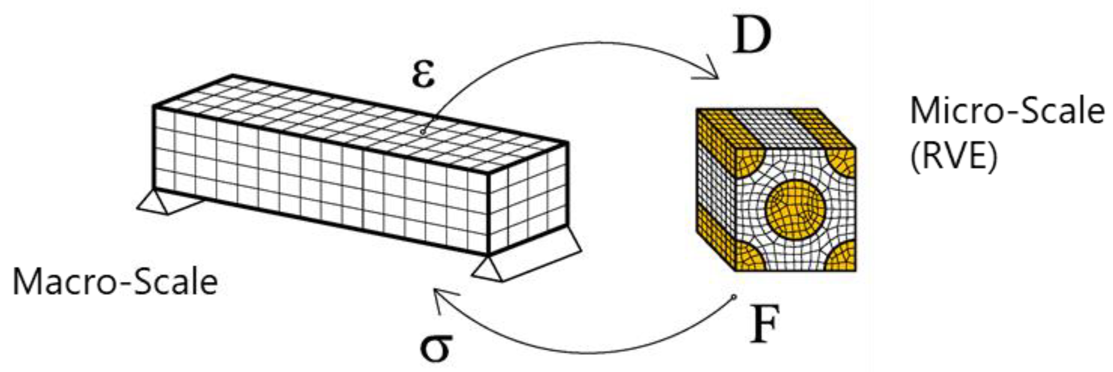
Numerical multi-scale models are of special relevance for the analysis of structures with a complex micro-structural behaviour, such as composites. In these cases, it is very difficult to define a constitutive law that captures accurately the mechanical performance of the material. Instead, a multi-scale approach uses a micro-structural model, defined by means of a Representative Volume Element (RVE), to obtain the material response. The material performance provided by the micro-model is used afterward by the macro-model of the structure to be analysed.
Figure 1 presents a schematic representation of a multiscale approach. This figure shows that the solution of the beam model (macro-structure) produces a set of strain fields that are converted to displacements in the micro-model in order to analyse its response. The results provided by the micro-model are a set of forces that are then transformed to stresses in order to feed the macro-model. In other words, the micro-model works like a constitutive equation of the material, as it provides the stress field associated with a given strain. With this approach, it is possible to obtain the elastic performance of composites with complex micro-structures (such as honeycombs, woven composites, etc.) as well as to predict the complex failure modes associated to these materials.
The mathematical foundations on which the multiscale analysis is based, as well as its detailed numerical implementation, can be obtained from the reference Otero et al. [
9]. In this work the authors show that the displacement to be applied to the micro-scale (RVE) can be obtained as the displacement of the macro-scale and the addition of a micro-fluctuation in the micro-model. This can be written as:
being
the displacement of the micro-scale,
the displacements of the macro-scale, and
the micro-fluctuations on the micro-model, which vary for each point in the microscale
.
Besides describing the displacement field of the micro-model, a multiscale method also need to relate the different scales considered. This is done with the average theorems [
34]. These theorems state that a given parameter in the macro-model can be obtained as the integral over the volume of this same parameter in the micro-model. If the average theorem is applied to the deformation gradient, the expression obtained is:
where
is the deformation gradient, in
, of the macro-structure,
is the RVE volume, and
are the deformation gradients in all RVE points. Equation (2) can be used to obtain the different displacement fields that are kinematically admissible in the micro-scale. In order to solve the equilibrium of the RVE at the micro-level, it is also necessary to define a set of boundary conditions. Among the different possible sets of boundary conditions that can be applied, this work will use periodic boundary conditions, which can be written as:
being
the parallel periodic boundaries in the RVE. With these boundary conditions, the kinematical constraint defines a periodic displacement fluctuation on parallel faces of the RVE.
Once solved the Boundary Value Problem (BVP) at the Representative Volume Element, the stresses in the macro-model can be obtained from the stresses computed at the micro-scale using the average theorem:
where,
and
are the stresses in the macro-model and in the micro-model respectively, and
V is the volume of the RVE.
The multiscale procedure previously summarized is described in detail in the work of Otero et al. [
9] and implemented in the CIMNE in-house finite element software PLCd [
32]. The abovementioned work also describes an enhanced approach that incorporates the second-order displacements of the macro-model in the displacement field of the RVE. A full second-order homogenization is proposed by Geers et al. in [
35]. Although current work will be limited to the linear-elastic performance of the structure, multiscale methods can account for material non-linearities. In this regard, Otero et al. [
36], and Zaghi et al. [
37] proposed different strategies to incorporate material-damage at the micro-structural level, with an affordable computational cost.
2.2. Multi-Objective Optimization Procedures
The multi-objective optimisation tool used in this work is RMOP [
33], the Robust Multi-Objective Optimization platform. It is a CIMNE in-house tool used along with the optimization analysis. It is an optimization platform that implements Genetic Algorithms, Particle Swarm Optimization methods and, Gradient Based methods.
RMOP is implemented as a set of libraries to open the possibility to implement new developments resulting from research. This coupling is done with a script, which can be defined using any programming or scripting language. The basic concept is that the solver works as a black box, so the optimizer is sending the request to the solver and this is answering the requested evaluation for both the objective functions and the constraints. This coupling can be done through the command line and ASCII files, but also using directly the RAM memory of the computer.
The Genetic Algorithm implementation in RMOP for the solution of multi-objective optimisation problems is based on the NSGA-II [
38]. It uses a λ + μ strategy and Crowded-Comparison Operator for the selection operator [
38], a Simulated Binary Crossover [
39] for the crossover operator, and a Polynomial Mutation [
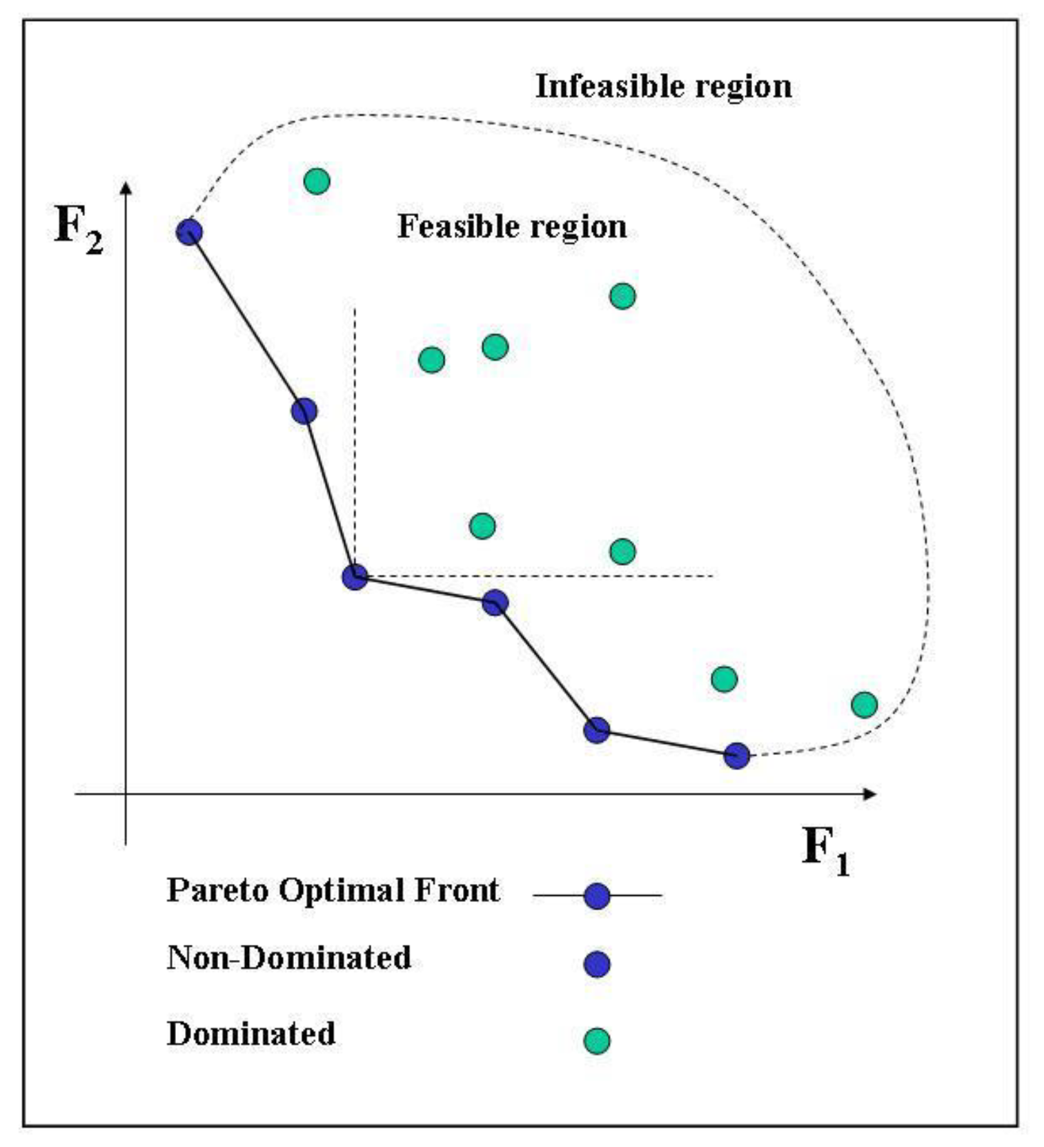
18] for the mutation operator. These operators define how the evaluated individuals are selected to become parents and how the new offspring are created. The results of a multi-objective problem are normally represented using the Pareto optimality or non-dominated individuals concept [
18].
Figure 2 shows this concept for a problem with two conflicting objective functions. For a given multi-objective problem, the solution is the Pareto optimal set resulting from the used optimization method. This gives a representation of all compromised designs between the two conflicting objectives. Real-world problems normally involve different conflicting objectives without any unique optimum design for all of them. In this case, a set of compromised solutions known as Pareto optimal (or non-dominated) solutions, can be obtained. A solution of a multi-objective problem is considered Pareto optimal if there are no other solutions improving all the objectives simultaneously. This means that an improvement in any of the objective functions implies a deterioration of any of the rest. The goal of solving the corresponding optimisation problem is then to provide a set of Pareto optimal solutions representing a trade-off of information amongst the objectives.
For a minimisation problem, a vector
is said partially less than vector
if, and only if:
In this case the solution dominates the solution .
As Evolutionary Algorithms (EAs) consider multiple points simultaneously, they are capable of finding a number of different solutions in a Pareto set. A comprehensive theory, literature review, and implementation of Multi-objective EAs (MOEAs) including the NSGAII and VEGA algorithms is given by Deb in reference [
18].
The RMOP platform is also enabling a pure hybrid approach. Two or more populations can be defined, assigning exploration and exploitation roles to each of them. The roles can be defined through the values of the probability of cross-over and mutation, or through the assignment of different objective functions and constraints to each population [
39]. Hybridization through the combination of optimization methods, as well as the mixing between multiple populations and a combination of methods is an ongoing development of the platform [
40,
41,
42].
2.3. Multi-Objective Multi-Scale Optimization Procedure
Once having defined the multi-scale procedure to be used in this work, which is implemented in the finite element code PLCd [
32], and the multi-objective optimization software RMOP [
33], this section describes the procedure used to couple both numerical tools, in order to perform a multi-objective, multi-scale optimization of eco-composite structures.
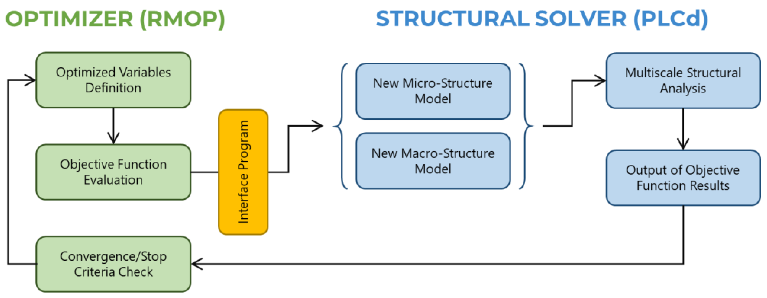
This coupling is conducted using an interface program that reads the results obtained from the numerical analysis made by PLCd, and sends them to the optimization code. Then RMOP takes the results obtained and uses them to generate new populations that can be analysed in order to obtain the optimal structure configuration. It also draws the Pareto front (
Figure 2) that can be used afterward by the user to select the most convenient solution for the structural problem solved.
The analysis of the results obtained from the different populations is made based on the objective functions to be optimized (either minimized or maximized). These objective functions are defined in the interface program, and can take data from the input data file of the structural solver (for instance, minimization of the stiffness required from the material) or from the output file (i.e., minimization of the deformation or of the maximum stresses).
Once the new populations have been defined, the interface program modifies the input data files required by the structural solver to run the new analyses. When the mechanical simulation is conducted using a multiscale analysis, the definition of the new simulation populations can be made by modifying either the parameters of the macro-model, the parameters of the micro-model or both.
The whole procedure is described schematically in
Figure 3.
3. Optimization Example, Application to an Aircraft Overhead Locker (Hatrack)
The structure chosen to validate the optimization procedure is the cabin stowage bin located above the seats in an airplane, this is also called hatrack. The hatrack is usually made with a sandwich material in which the core is a honeycomb and the skins are made of a woven glass-fibre embedded in a phenolic resin. In this work, the honeycomb core is made of aramid and cellulose, and the skins are made with a ramie woven embedded in an eco-epoxy matrix.
This section describes, first, the considered hatrack and the numerical model developed. Afterwards, two different optimization analyses are presented. The first one looks for the best possible orientation of the woven skins in the hatrack shelf. This optimization affects only the macro-structural model of the hatrack. The second optimization analysis conducted affects both, the macro- and the micro-scales of the model, as it looks for the best woven orientation as well as for the optimal micro-structural configuration of the laminate. The comparison of both analyses shows that, in order to obtain the best possible solution, the composite microstructure is as important as its orientation in the structure.
3.1. Aircraft Overhead Locker to Be Optimized
3.1.1. Geometry
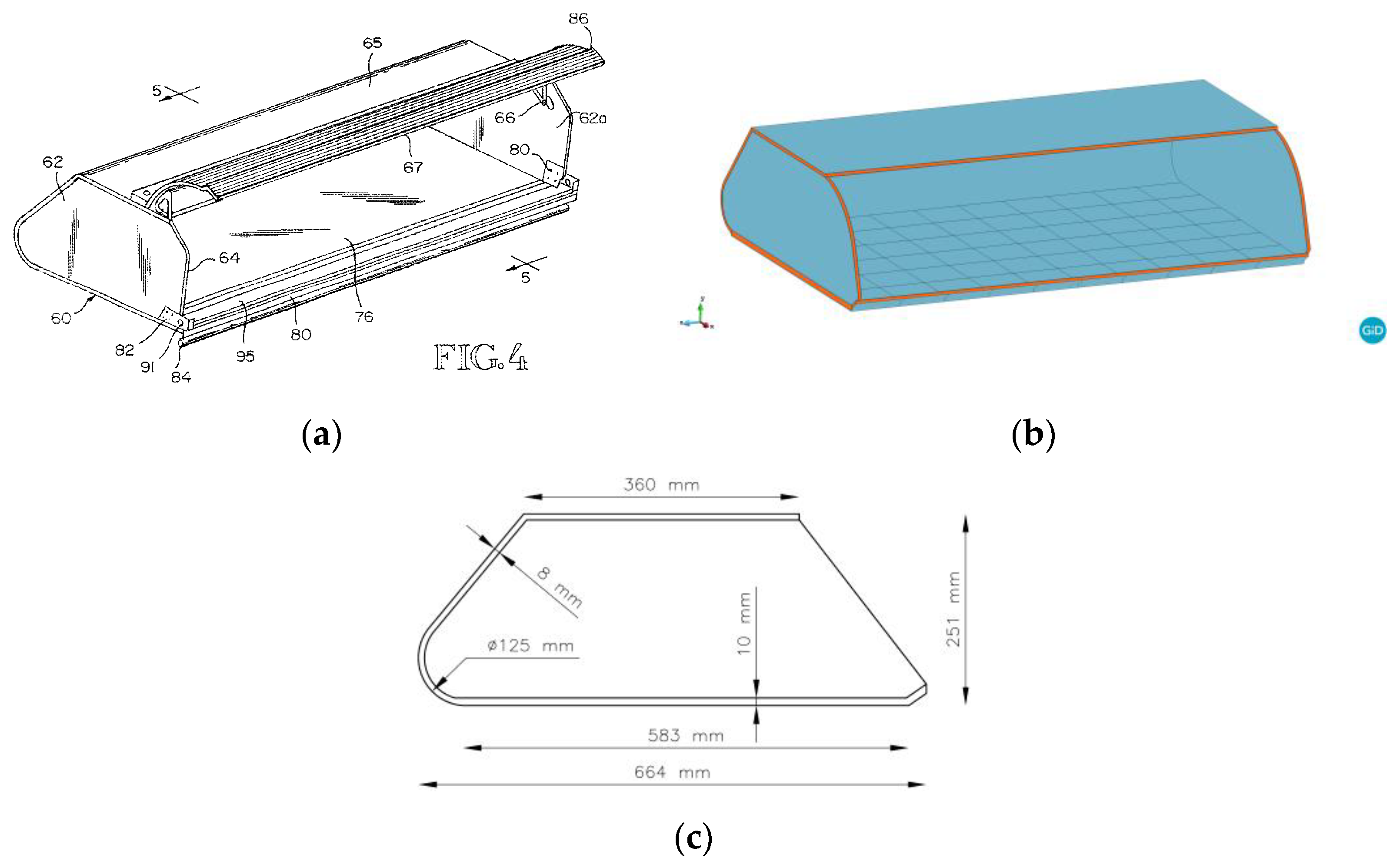
A hatrack is the cabin stowage bin located above the seats in an airplane. The hatrack considered has been obtained from the patent of Welch and Roth [
43]. It is subjected to three fuselage frames, which are at a distance of 20 inches. Therefore, the hatrack has a length of 40 inches (1016 mm), a width of 583 mm, and a height of 251 mm. Its exact geometry is shown in
Figure 4.
The main interest of the current analysis is focussed on the performance of the hatrack shelf (element 76 in
Figure 4a), as this is where the largest stresses and strains are found. To minimize the computational cost of the model, all non-structural parts have not been included (e.g., the hatrack door and its lock). Another simplification made on the geometry is in the areas where the hatrack attachments to the fuselage are located. These regions have large stress concentrations and require of specific reinforcements to sustain the loads. Usually, in these spots, the core material is filled with resin to create a monolithic region. For the sake of simplicity, these reinforcements are not defined in the model. Therefore, stress concentrations in these regions will be ignored.
3.1.2. Boundary Conditions
As it has been already mentioned, the hatrack is attached to the three fuselage frames that are located along its length in the upper and lower panels. This defines a total of six supports, as shown in
Figure 5. In the model, this boundary condition is applied by restricting the displacements in the three spatial directions, along a line with a length of 30 mm.
As for the loads applied, a hatrack with these dimensions is allowed to support a total of 50 kg of weight due to the luggage stored in it (live-load). A dead-load of 20 kg has to be added to the live-load, which accounts for the actual weight of the hatrack, plus the weight of different systems attached to it such as the intercommunication elements, the lights, the oxygen masks, etc. The total load of 70 kg is applied to the shelf of the bin. This is correct for the luggage and the systems attached to the hatrack, but not for the self-weight, which is distributed along the whole geometry. Applying the load in such a manner has been done for the sake of simplicity and provides an extra safety factor.
The structural analysis will consider two different limit states. The Service Limit State (SLS) will apply the weight of 70 kg multiplied by gravity and divided by the area in which it is distributed. It defines a pressure of 1.14 × 10
−3 MPa to be applied at the shelf. This load will be used to verify the maximum displacement suffered by the hatrack in service conditions. The other case corresponds to an Ultimate Limit State (ULS). In this case, the load is affected by a gravity acceleration of 8 g, as it is defined in Certification Specification CS-25 provided by EASA [
44]. In this case, the applied pressure is 9.15 × 10
−3 Mpa and this load will be used to evaluate the stresses found in the structural elements.
3.1.3. Materials
The hatrack is made with a sandwich laminate in which both, the skins and the core, contain eco-materials. The skins of the sandwich are made of woven ramie fibres embedded in a partly rosin-based epoxy matrix (AGMP 3600 [
45]). The core is made with a honeycomb that contains a high percentage of cellulose.
Two different sandwich laminates are used in the hatrack. The shelf, in which the luggage is placed, has a total thickness of 14 mm, with a core of 10 mm and two skins of 2 mm each. The rest of the hatrack has a thickness of 8 mm, with a core of 6 mm and skins of 1 mm each. The mechanical performance of the skin and core materials is obtained using a multiscale strategy, with the definition of a RVE to represent the woven skin and another RVE to characterize the honeycomb core.
Sandwich skins
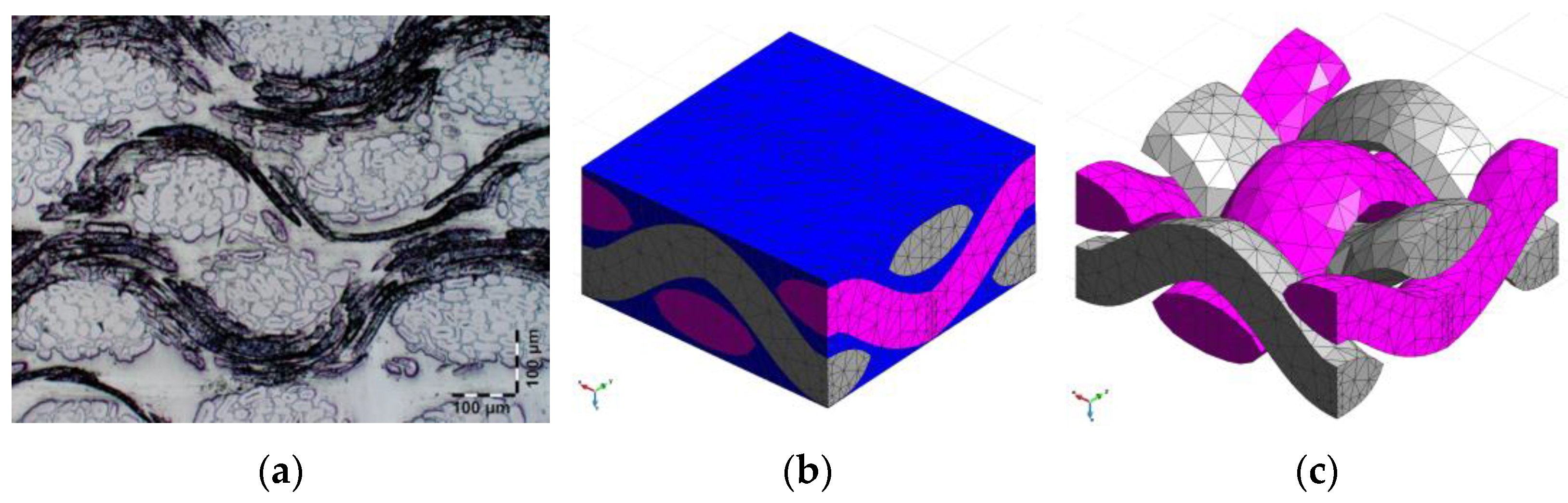
This section describes the Representative Volume Element Model developed to characterize the woven ramie laminate used for the sandwich skins. The geometry of the representative volume element has been generated using a micro-photograph of the composite. Both, the micro-photograph and the geometry of the model developed, are shown in
Figure 6. The mesh of the RVE contains 9547 linear tetrahedral elements and 2287 nodes.
As it is shown in
Figure 6b, the representative volume element has been defined with three different bulk materials, fibres in X direction (grey), fibres in Y direction (pink) and matrix (blue). Fibres in X and Y directions have exactly the same mechanical properties and differentiation has been made in order to have the possibility of changing them in the optimization process. The mechanical properties of ramie fibres have been obtained from average values shown in publications [
46,
47], and the properties of the epoxy resin come from the manufacturer’s specifications. These properties are described in
Table 1. The fibre volume content in the prepeg is 51.4%.
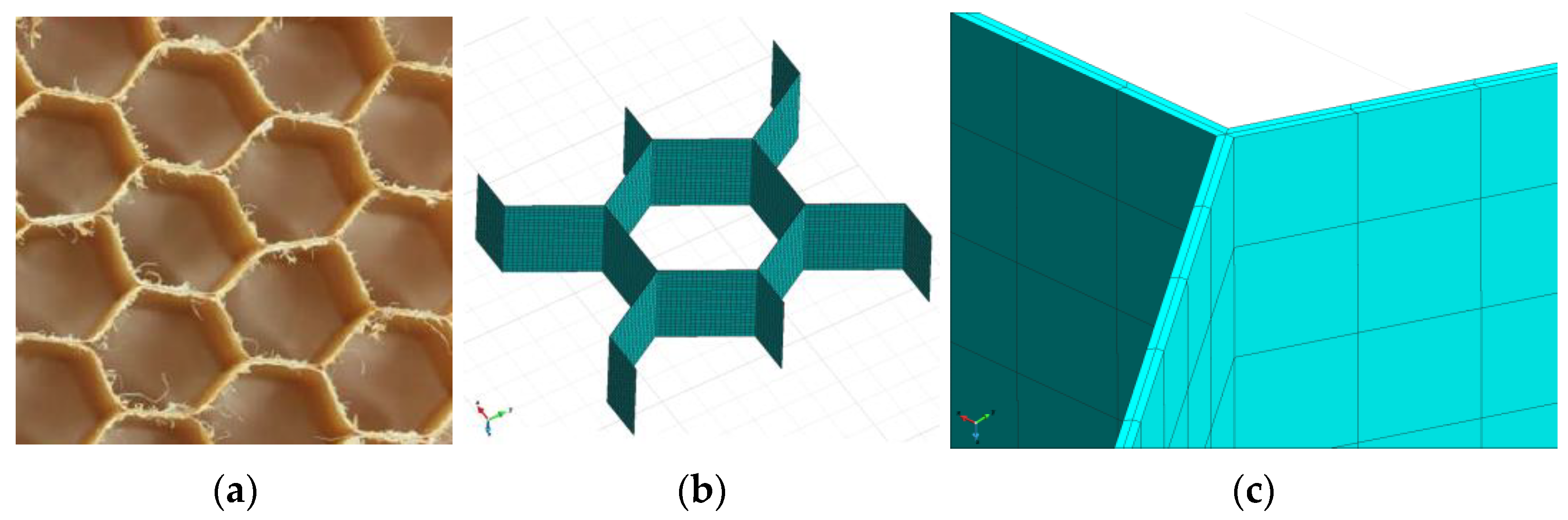
Sandwich core
The green-honeycomb core used for the analysis is an aramid paper core with a high percentage of cellulose. The material has been characterized with a Representative Volume Element which geometry has been defined from available photographs of the actual material. The material and the RVE model developed are shown in
Figure 7. The mesh of the RVE has 9600 linear hexahedral elements and 15,666 nodes. A detail of the mesh is included in
Figure 7c, where it is shown that there are two elements along the thickness of the honeycomb in order to capture the possible (although not probable) bending of the honeycomb paper.
The material properties defined for the hybrid cellulose-aramid films that constitute the honeycomb are described in
Table 2.
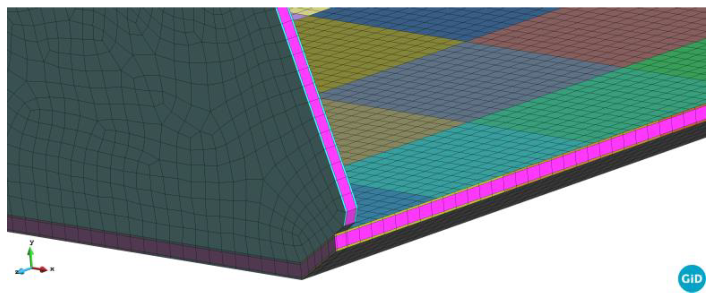
3.1.4. Hatrack Finite Element Mesh
The hatrack is discretized with linear hexahedral solid elements. It has 79,173 elements and 106,276 nodes.
Figure 8 shows a detail of the mesh. The laminate has three finite elements along its thickness, one corresponding to the core (pink elements in
Figure 8) and two, one at each side of the core, corresponding to the woven skins. The mesh defined corresponds to a compromise between results accuracy and computational cost, as the structural model has to be analyzed many times during the optimization procedure.
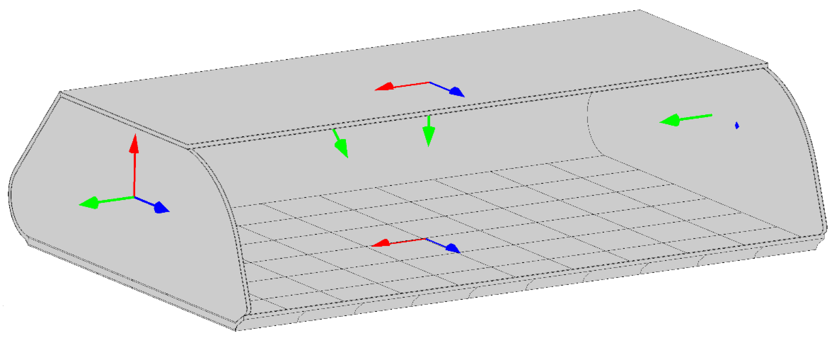
3.1.5. Laminar Orientation
When working with composite structures, one of the most important aspects is the orientation of the composite in the structural element, as composites are highly orthotropic in terms of strength and stiffness.
Figure 9 shows the original axis defined for the different hatrack elements. In this drawing the X, Y, and Z axes are represented in blue, red and green respectively. This orientation has been applied to the woven ramie prepreg and to the honeycomb.
Figure 9 also shows that the hatrack shelf is divided into 6 × 10 rectangular elements. This division has been made to facilitate the definition of different woven orientations in the optimization problem.
3.1.6. Hatrack Structural Performance
The hatrack has been analysed with the materials and boundary conditions previously described. This analysis provides the performance of the hatrack in its original configuration and will be compared with the improved response after conducting the optimization analysis.
Deformation under Service Limit State (SLS) loads
The deformation of the hatrack under SLS conditions is depicted in
Figure 10. In this case, the load applied is a pressure load at the shelf surface, with a value of 9.15 × 10
−3 Mpa. Under this load, the larger deformations are found at the centre of the free border of the shelf, and the value of the vertical displacement is 4.22 mm. The deformations of the hatrack under Ultimate Limit State (ULS) loads is eight times bigger, as the loads are also eight times bigger and the model is linear. In this case, the maximum displacement is 33.7 mm.
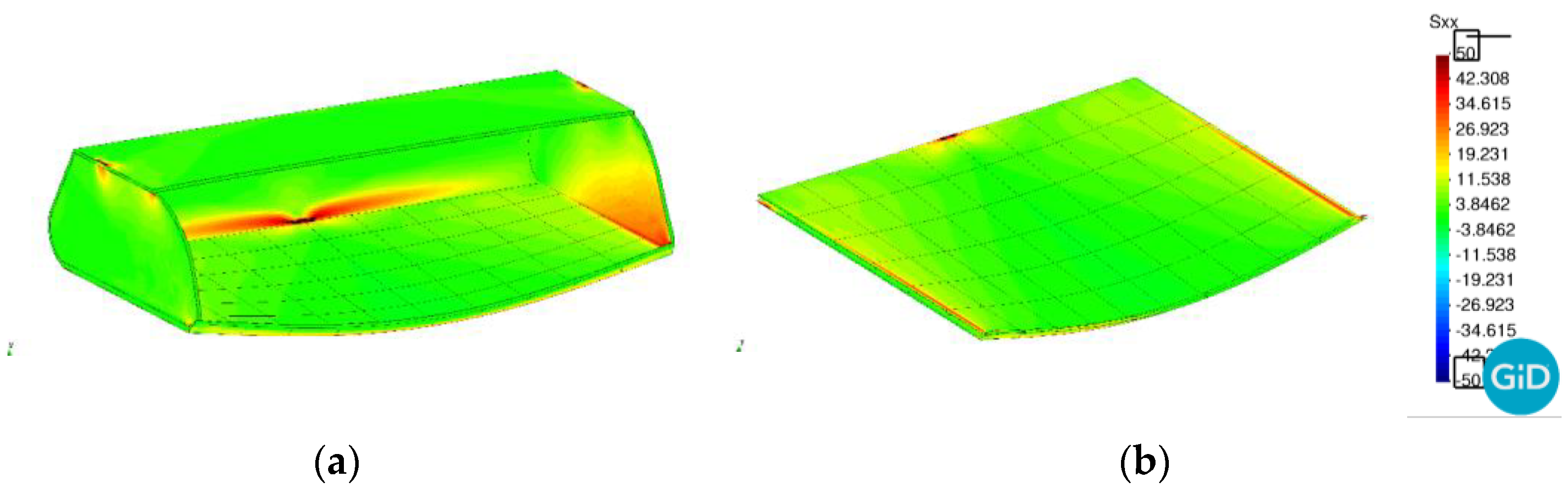
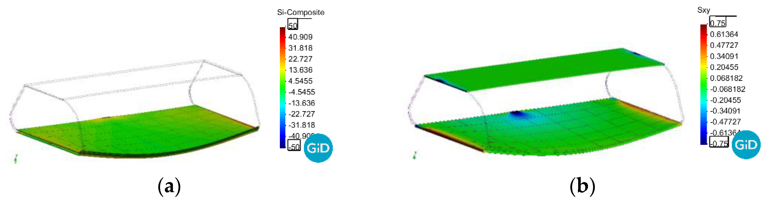
3.1.7. Stresses under Ultimate Limit State (ULS) Loads
The structure validation also requires that the maximum stresses under ULS loads do not reach the threshold value. The maximum tensile stress for the sandwich skin is limited to 59 Mpa, and the maximum shear stress allowed in the honeycomb is limited to 0.73 Mpa.
Figure 11a shows the maximum tensile stress (first principal stress) in the skins of the hatrack. These stresses are larger at the back, close to the support area, and on the sides, close to the opened area. It is possible to see also stress concentrations around the different support regions.
Figure 11b shows these same stresses in the hatrack shelf. These two figures show that at no point the maximum stress of 50 Mpa is exceeded, except in the support regions (where the hatrack is fixed to the airplane frames). The stress concentration in this regions is not plotted to avoid hiding the rest of the results.
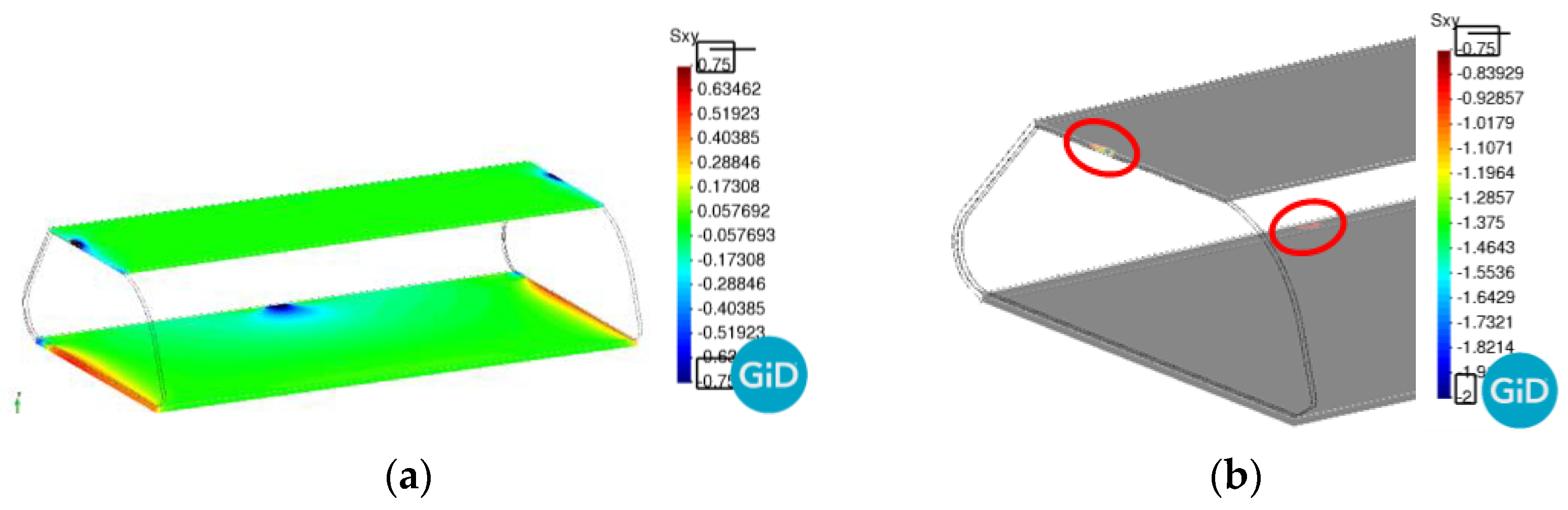
Figure 12 shows the shear stresses in the honeycomb core at the shelf. In this image it is shown that they do not exceed the maximum stress value of 0.73 MPa at any point except, again, at the regions where the hatrack is fixed to the airplane frames.
The stress results shown in previous figures prove the validity of the designed model to sustain the applied loads under the Ultimate Limit State. The only regions where the maximum loads are exceeded are those in which the hatrack is fixed. To handle these stress concentrations, in these regions the honeycomb core is filled with resin, obtaining a stiffer material that can easily handle the applied loads. The design of this structural detail is not within the objectives of this work and, for this reason, these larger stresses are disregarded.
3.2. First Optimization Analysis: Optimal Fibre Alignment for an Improvement of Structure Stiffness
The first optimization analysis conducted aims to improve the stiffness of the hatrack shelf by finding the optimal orientation of the woven skins. With this aim, the numerical model has divided the shelf into a total of 60 regions, 6 rows by 10 columns (see
Figure 9), in which it is possible to define independent orientations. The stiffness of the shelf is evaluated with the displacement obtained at the centre of the free edge, where the maximum displacements are found, as shown in
Figure 10. Therefore, the objective function here is the maximum vertical displacement in a given point (centre of the free edge of the shelf), which will be minimized. In order to achieve this, the algorithm can modify 60 different angles, each one corresponding to the skin orientation at each of the rectangular elements shown in
Figure 9.
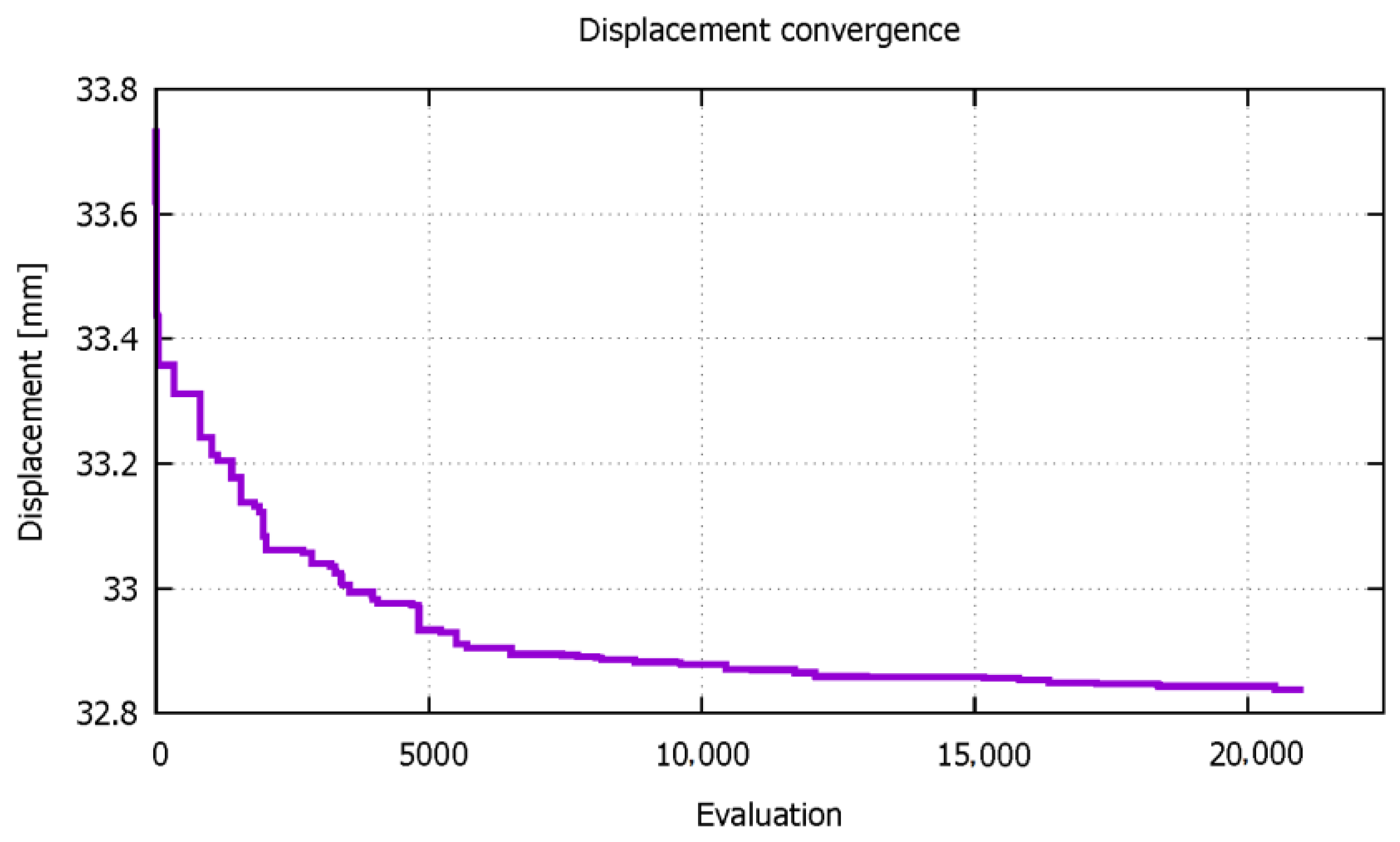
The initial displacement, under ULS loads and with the orientation following the X and Y axis shown in
Figure 8, is 33.7 mm. With this initial deformation, the coupled PLCd-RMOP software is run, and the maximum displacement is evaluated after each structural solver analysis.
Table 3 describes the set-up parameters for the RMOP optimizer, applied to the described application. The evolution of this displacement with the different evaluations made of the model is shown in
Figure 13. This figure shows that the optimization software has been able to reduce the displacement of the structure with successive iterations, reaching an asymptotic value of 32.8 mm
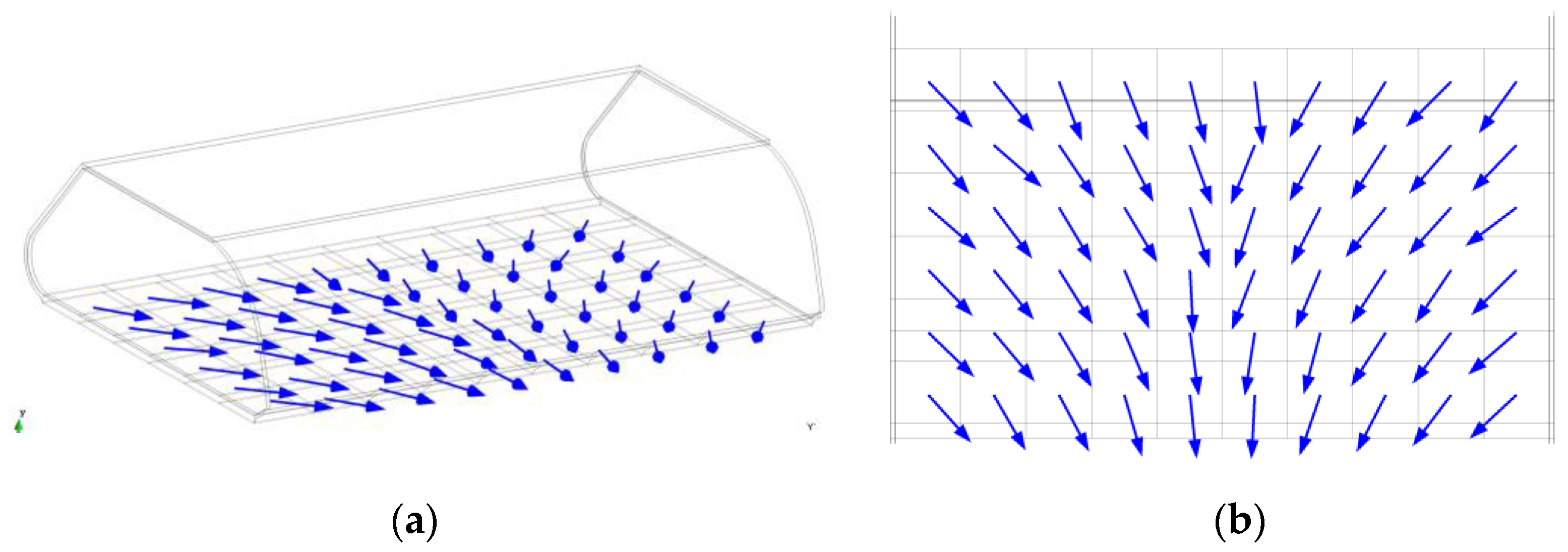
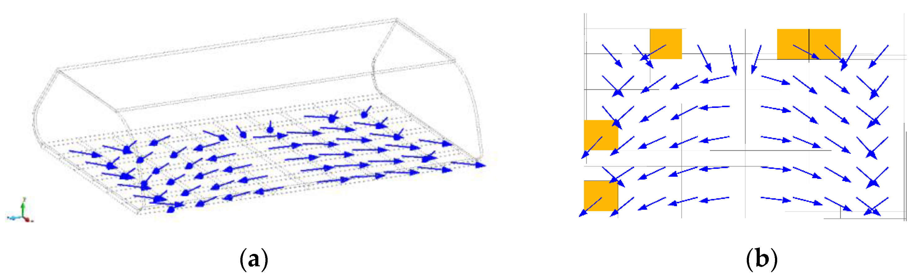
The woven skin orientation that sh”uld ’e defined to obtain the minimum displacement is shown in
Figure 14. This picture shows that centre skins should maintain their original orientation, which is perpendicular to the shelf lip, while the outer skins must be oriented looking approximately towards the point of maximum deformation. This analysis validates the procedure to optimize the design of the hatrack.
The results also show that the improvement obtained in the structure stiffness with the optimal woven disposition is only 0.9 mm for the ULS loads, which is only 2.7% of the original deformation. Therefore, it can be concluded that in this case, the orientation of the woven composite in the shelf does not play a significant role in the hatrack shelf stiffness.
As for the structural performance of the cabin bin, it is very similar to the performance previously seen. The displacement obtained with the numerical model is shown in
Figure 15, where it is seen that the displacement pattern is identical to the one obtained with the woven without an optimized alignment.
Figure 16a,b shows the maximum tensile stresses in the sandwich skins and the shear stresses in the core, respectively. In both cases, the stress threshold is not exceeded except in the support regions. The results shown in these figures prove that the optimized design is valid and that it is possible to increase the stiffness of the hatrack shelf with a specific orientation of the woven skins in the sandwich laminate.
3.3. Second Optimization Analysis: Multi-Objective, Multi-Scale Optimization
The second analysis made is a multi-objective, multi-scale optimization. Two different objective functions are defined to obtain the optimal design of the structure. The first one corresponds to the shelf stiffness, which is measured as the in previous case, by minimizing the vertical displacement at the centre of the free edge. The second objective function consists on minimizing number of fibres placed in one of the woven directions, which seeks a reduction on the material cost and weight (flax fibres density are about 1.5 g/cm
3 [
48], while epoxy resins have densities around 1.2 g/cm
3 [
3]). To obtain the optimal design, the software will modify the woven skin orientation, as has been done in the previous case, and will also modify the material configuration by reducing the amount of fibres in one of the directions of the woven material.
Table 4 describes the set-up parameters for this second and multi-objective test case.
The fibre reduction is achieved by varying the stiffness of fibres in the Y direction of the Representative Volume Element defined to characterize the ramie woven prepreg (7b). This stiffness reduction is defined using the parallel mixing theory [
49] to obtain the fibre yarn stiffness, as it is shown in Equation (6), assuming that the maximum stiffness is obtained if all the yarn contains ramie fibre, and that stiffness is reduced by adding some percentage of rosin epoxy resin in the fibre yarn. If this percentage reaches 100% there will be no fibres in the yarn, which provides a material similar to a unidirectional composite. In Equation (6),
,
and
correspond to the stiffness of the bundle, the ramie fibres and the rosin epoxy matrix, respectively, and
kf is the volumetric participation of fibre.
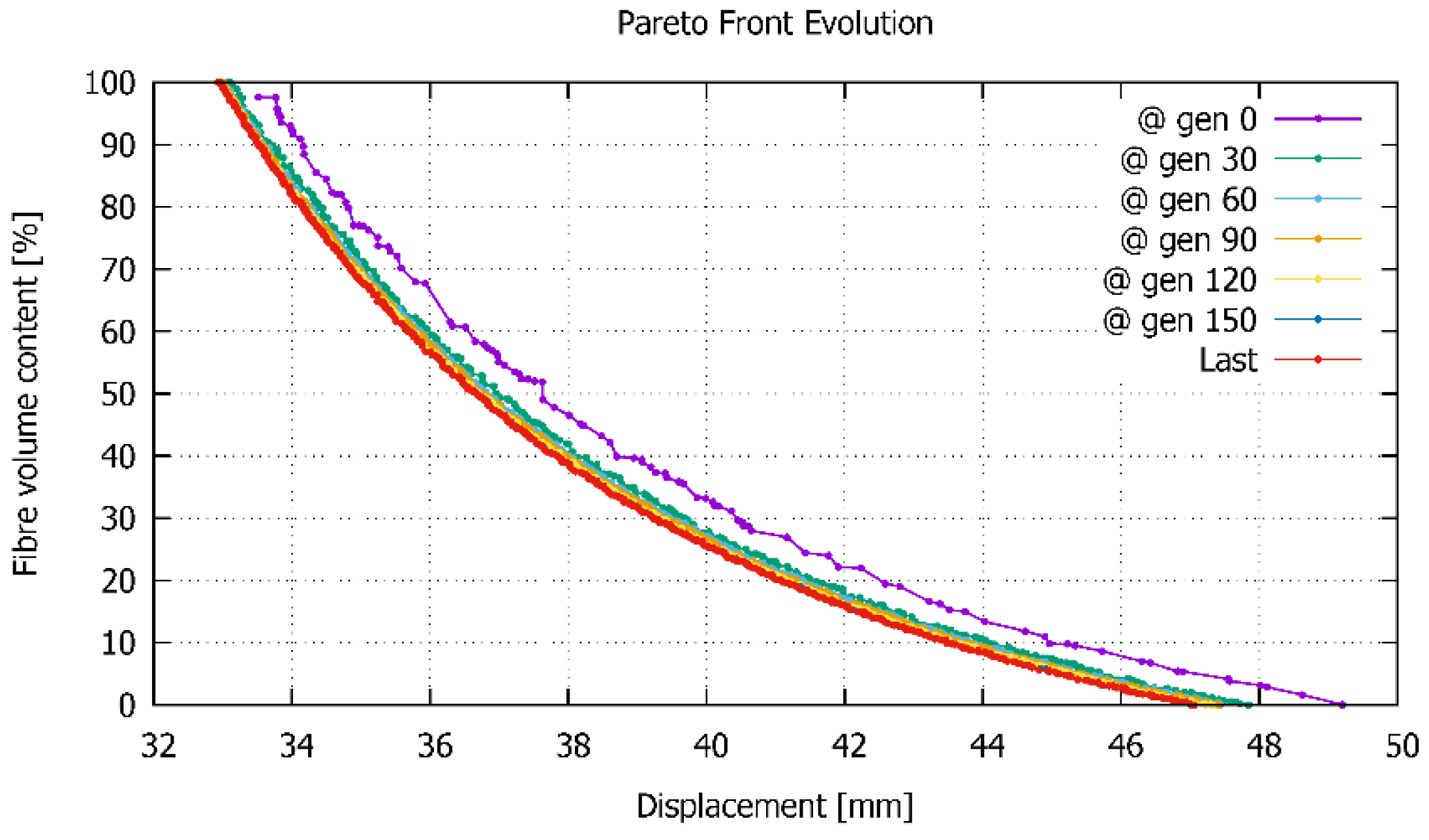
In a multi-objective optimization analysis, there is not an optimal case, but a set of cases that provide an optimal result for one of the objective functions, for a given value of the other objective function. This set of results are represented in the Pareto front, which shows the best candidates obtained by combining both variables.
Figure 17 shows the Pareto front after several evaluations. This figure shows that the evolution of this front from the first analysis (purple line) to the evaluation 30th (green line) is quite visible, and that after evaluation 30th the difference is minimal. The final result is obtained after 150 evaluations and it is shown with a red line.
The results shown in
Figure 17 for a fibre volume content of 100% are the same that were obtained in the first optimization analyses conducted, in which the original displacement is close to 34 mm. This displacement can be reduced to 33 mm with a correct fibre disposition. On the other hand, if we consider the case in which we remove all fibres in Y direction, the deformation of the hatrack shelf becomes substantially larger, being of 47 mm if fibres are oriented in the optimal situation, and 49 mm otherwise. Between these two limits, there is a wide range of solutions, providing different displacements for different fibre volume contents.
Figure 17 also shows that the slope of the Pareto front is substantially steeper for the fibre volume contents between 100% and 60% than for lower fibre volume contents. In other words, a reduction of 10% in fibre volume for higher fibre volume fractions has a lower implication in the shelf displacement, than this same reduction is applied in lower fibre volume fractions. A limit between these two tendencies is found around a fibre volume content of 60%, in which we have an increase from 33 mm to 35.5 mm (7.5%) in the maximum vertical deformation of the shelf, with a reduction of a 40% of fibre volume content. Therefore, from an engineering point of view, this can be an optimal design for the hatrack.
Considering this case as the optimal design, in the following the results obtained for this case are described. The first result shown is the orientation of the woven skin in the hatrack shelf.
Figure 18 shows the directions of the stiffer skin yarns that are required to obtain the best structural performance. Now it is important to bear in mind that the woven skins are orthotropic, as the yarns in the X direction (the one represented in
Figure 18) contain 40% more fibres than in the perpendicular direction. If the orientation obtained for this case is compared with the orientation in the case of a regular woven laminate, with the same amount of fibres in both directions (
Figure 14), it can be seen that in the central region of the hatrack, the yarns with a larger amount of fibres have to be placed perpendicularly to the direction obtained in the case of having the same yarns in both directions. On the other hand, in the region close to the edges, the stiffer yarns are perpendicular to the central ones, stitching them.
The comparison of fibre distribution displayed in
Figure 14 and
Figure 18 show that the optimal pattern has a large dependence on the structural configuration of the woven laminate. Which justifies the convenience of multi-objective, multi-scale optimization methods to obtain the optimal structural design of eco-composite structures.
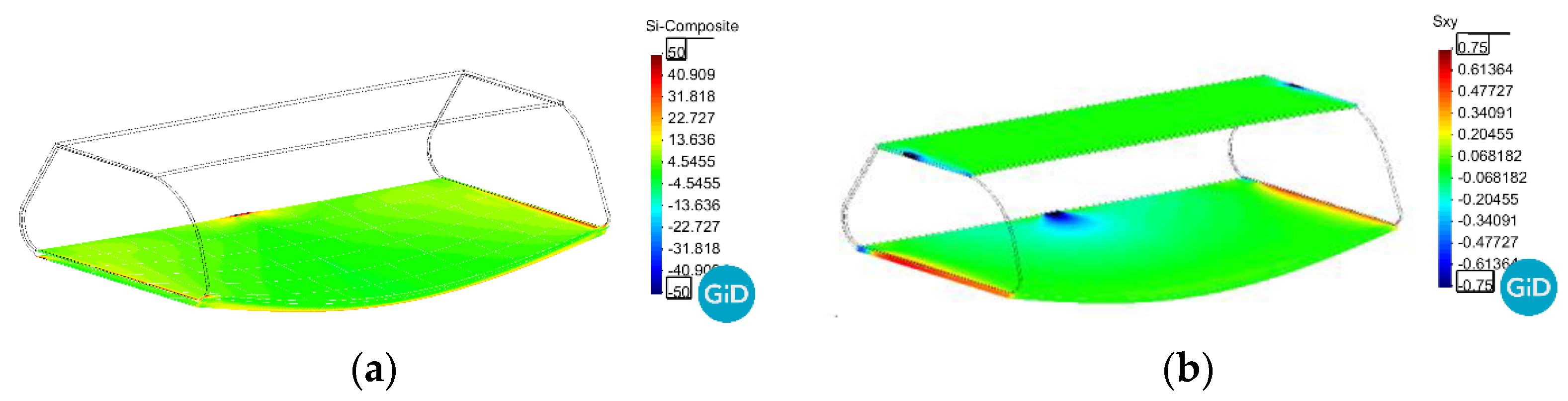
With this new fibre distribution, the structural performance of the hatrack is very similar to the one observed in previous analyses. Deformations follow the same pattern shown by previous models (
Figure 19), although in this case the maximum displacement obtained is a bit larger, as it has a value of 32 mm under Ultimate Limit State loads. As for the stresses, they are below the failure threshold (
Figure 20a,b). Therefore, the hatrack is feasible under this configuration, although its stiffness has been reduced due to the reduction of fibre content.
4. Discussion
The three numerical models analysed in
Section 3.1,
Section 3.2 and
Section 3.3 have shown the performance of an aircraft overhead locker with three different material configurations. The first analysis shows the performance of the locker when the woven composite of the skins is oriented following the length and width directions of the structure (as it is shown in
Figure 9), while in the other two simulations these orientations are defined using an optimization procedure. The first optimization analysis (
Section 3.2) been made with a single objective function and modifying the structural configuration only at a macroscale level. This analysis has provided the optimal fibre orientation of the laminate skins in order to improve the stiffness of the hatrack shelf. The second optimization analysis (
Section 3.3) has been conducted with two different objective functions, one consisting in obtaining the larger stiffness of the hatrack shelf, and the other one that seeks using the minimum amount of fibres in one of the directions of the woven skins (reducing the cost and the weight of the woven material). The modifications made on the structure design to obtain the optimal performance have been the orientation of the shelf skins and the number of fibres of the woven composite, in one of its directions. This last modification is made at a micro-structural level, as it modifies the configuration of the Representative Volume Element.
The results obtained with the solution of both optimization problems have proved the capability of the software developed to obtain an optimal design of eco-composite structures. In both analyses, the optimal fibre orientations differ from the orientations considered in the original hatrack (analysis made in
Section 3.1). However, the authors consider that the most relevant result is obtained from the comparison of the two optimization analyses conducted, as these have shown that a multi-objective optimization that modifies both, the macrostructure and the micro-structure, can provide solutions not considered by a regular optimization procedure. This opens a new framework in the design of composite structures, as now the material can be optimized at different scales, in order to provide the best possible material configuration, material disposition and structural configuration, for a given application. This framework is not found in other optimization analyses, in which either apply an optimization procedure to a multi-scale problem, or they use a multi-objective optimization to a structural problem, but not both.
Although the results demonstrated the capabilities of the proposed methodology, it has some limitations and drawback that the authors must further research. The use of a population-based optimizer requires a large number of simulations, which means a large computational cost. Parallelization is already in place, but further research is required to ensure the applicability to larger structural problems. The coupling between the optimizer and the multi-scale simulator is using a weak form, but hierarchical optimization or hybridization strategies could be developed to further benefit from all the scales. In this same line, any strategy aimed to reduce the computational cost of multiscale structural models will benefit the whole procedure, as multiscale methods are rather expensive and this limits the complexity of the models that can be considered in the optimization process.
The overhead locker analysed in this work is used mainly as an example of the capabilities of the proposed formulation. However, looking at the specific application, additional improvements of the design could be obtained by acting on the detailed geometry of the micro-structure, e.g., by considering a different weave pattern, or by modifying the hatrack shape at the macro-level.
5. Conclusions
The introduction of eco-composites in engineering structures and, more specifically in aeronautic structures, requires improving the existing knowledge about the material performance, and also to develop analysis tools capable of predicting the response of the material when it is in service. An optimal design of eco-composite structures needs the developed numerical tools to evaluate the structural performance and to correct its design, if necessary, in order to improve it.
Optimization tools provide a systemized solution for design improvement. Instead of relying on the designer experience to obtain a new structural configuration that provides better performance, it is possible to rely on an optimization code to do the work. In this case, the software analyses the variables that define the structure performance and, based on different procedures (e.g., genetic algorithms), defines new structure configurations that are expected to improve the structural performance.
Current work has coupled a multi-scale structural finite element software, PLCd, with a multi-objective optimization software, RMOP, to obtain a multi-objective multi-scale optimization package that can be used to obtain the optimal design of eco-composite structures. With this approach, it is possible to optimize the structural performance by modifying the configuration of the structure at a macro-level, but also having the possibility of modifying the configuration of the internal micro-structure of the composite material. The analysis conducted with the developed tools has shown that with the multi-scale multi-objective approach proposed, it is possible to obtain improved structural configurations, not reachable by the optimizer otherwise. These tools are expected to facilitate the use of these new materials in different structural applications, and especially in aeronautical structures, in order to reduce the environmental impact of transportation.


 ,
, 


