Article

An Adaptive Protection Scheme Based on a Modified Heap-Based Optimizer for Distance and Directional Overcurrent Relays Coordination in Distribution Systems

1
Department of Electrical Engineering, Faculty of Energy Engineering, Aswan University, Aswan 81528, Egypt
2
Department of Electrical Engineering, College of Engineering, Jouf University, Sakaka 72388, Saudi Arabia
3
Department of Nuclear and Renewable Energy, Ural Federal University Named after the First President of Russia Boris Yeltsin, 19 Mira Street, 620002 Ekaterinburg, Russia
*
Author to whom correspondence should be addressed.
Mathematics 2022, 10(3), 419; https://doi.org/10.3390/math10030419
Submission received: 20 December 2021 / Revised: 21 January 2022 / Accepted: 25 January 2022 / Published: 28 January 2022

Abstract

:
This paper proposes an adaptive protection scheme (APS) based on the original heap-based optimization (HBO) and a modified HBO (MHBO). APS is used to solve protection relays coordination problems that include directional overcurrent relays (DOCRs) as well as the distance relay’s second zone times. The complexity of the coordination problem increases with the impact of distributed generators (DGs) switching (ON/OFF). Topological changes in grid configuration frequently occur in distributing networks, equipped with DGs, causing changes in the values and direction of short circuit currents. This issue becomes a challenge for protection systems to avoid relays miscoordination and save a network’s reliability. In the proposed MHBO, the Original HBO is modified by three points, population are divided into subgroups, then they are unified into one group gradually, those subgroups are exchanging some search agents between themselves, these search agents are called travelling agents, and the last one is about, upgrading an internal equation in the original algorithm. For validating the proposed relays coordination, the IEEE 8-bus test system, and the IEEE 14-bus distribution network are selected as case studies. The obtained simulated results of the proposed algorithm show better performance compared with those obtained by the previous algorithms.

1. Introduction

The area of protection is currently one of the most important fields in power systems. To protect transmission lines, both directional overcurrent relays (DOCRs) and distance relays are generally used. Transmission lines are monitored by these protection relays from both ends. The occurrence of faults causes relays to activate trip scenarios [1].
Overcurrent relays (OCRs) generally operate based on the magnitude of the fault current, which is selected within parameters of the relay, whereas DOCRs incorporate the direction of the current flowing through the transmission line. A potential transformer is used to determine the direction of the voltage phasor. DOCRs are thus more costly than traditional OCRs. However, they are more advantageous than OCRs. Those kinds of relays must be set to operate as the backup, with a time delay greater than that of the primary relay [2].
Distance relay has two main zones. After detecting a fault, the first one begins working immediately. To avoid calculation errors, 80 percent of the transmission line is covered by this zone. The second zone then covers up to 120 percent of the transmission line by delay time. This large area also includes a portion of another transmission line [3].
The main issue in this paper is about the reduction of the operating time of the protection relay in order to provide the protection devices with the ability to isolate the fault area. This extends the lifespan of the components of the power system, making the system more reliable and healthier. However, because of constraints between DOCRs pairs and DOCRs and distance relay pairs, DOCRs and distance relays have more constraints and complex coordination problems. The miscoordination of these protection relays overlaps protection operations and fails to take advantage of the benefits of both distance and DOCR relays [4,5].
The contribution of RES-based distributed generators (DGs) to a distribution system is important. RES such as solar and wind energy are integrated into power systems. Many challenges are presented by DGs and problems with coordination, some of which include the change in the flow of the direction of fault currents and their magnitude [6].
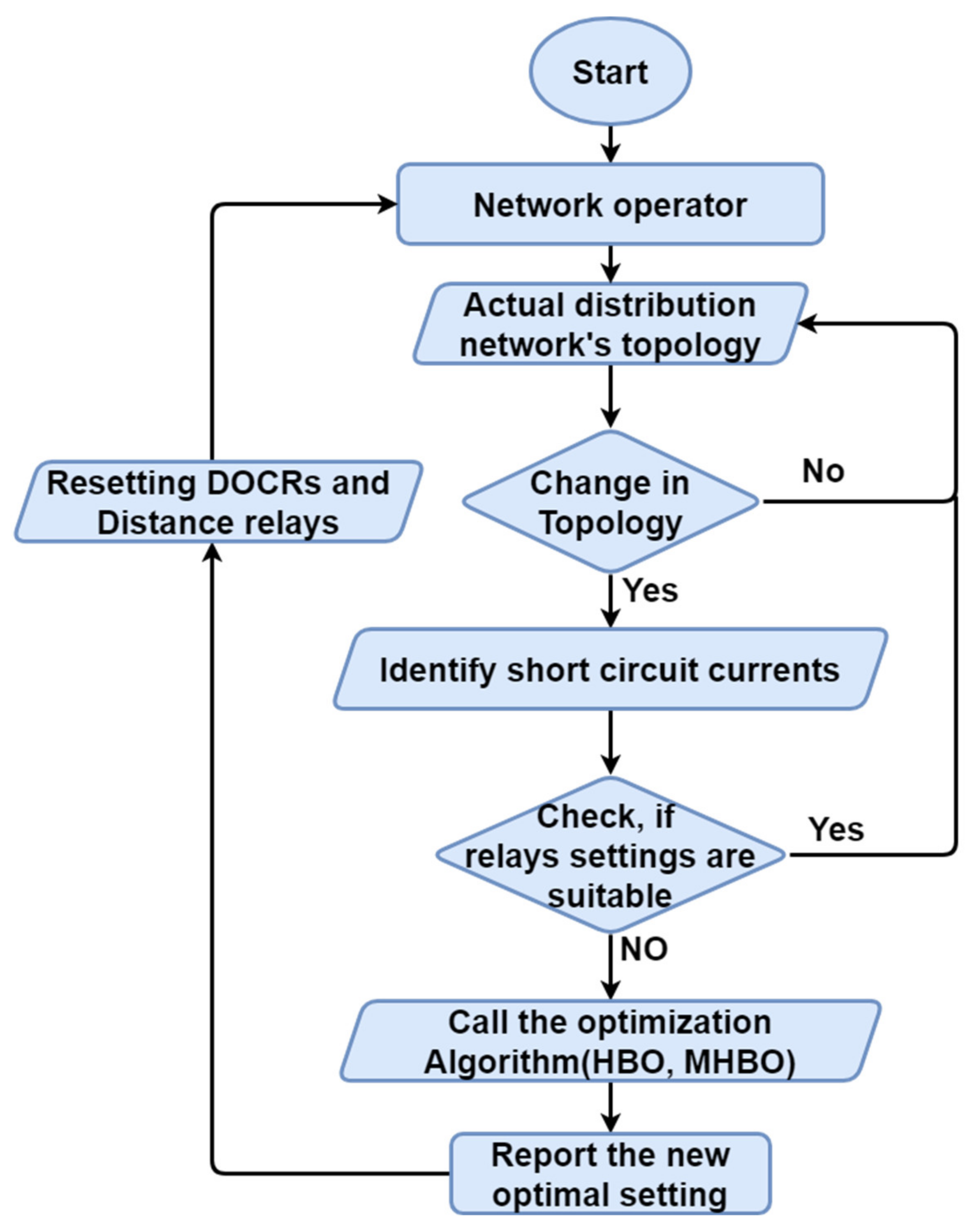
Due to the impact of DGs on distribution networks, the protection system necessitates a flexible structure. In order to solve the problem of protection relays coordination, this research presents the adaptive protection scheme (APS) as a solution for this challenge. APS enables the changing of relay settings for both DOCRs and distance relays in response to any changes in the state of a network, based on the DG’s ON/OFF states, using predetermined settings. APS, as a component of information and communication technologies (ICT), is primarily dependent on the communication network between smart grid components, or on SCADA. These communication networks enable APS to remotely set relay settings. APS is tested with a variety of scenarios that are most likely to trip in-network, and the best protection relay setting in each scenario is determined. This enables the protection system to reduce miscoordination and malfunction. The primary benefit of APS is to improve the selectivity and reliability of the protection system over traditional or fixed systems. The APS configures a group of protection relays that are determined by calculating optimal settings for each scenario using an optimization algorithm based on the DG’s states [7,8].
Adaptive systems are designed to work on real-time systems. They need fast methods to rearrange their system’s items. Hence, the APS uses the optimization algorithm due to its fast performance. APS is addressed in many research papers, which were developed based on optimization algorithms such as particle swarm optimization (PSO) in [9], genetic algorithm (GA) in [10], differential evolution algorithm (DEA) in [11], ant colony optimization (ACO) in [12], firefly algorithm (FA) in [13], gravitational search algorithm (GSA) in [14], manta ray foraging optimization (MRFO) in [7], and hybrid Harris hawks optimization (HHO) in [15] in order to coordinate the process of DOCRs.
In [1], APS was used to coordinate DOCRs and distance relays using school-based optimization algorithm (SBO) and its modified algorithm (MSBO). In this paper a new APS is suggested to solve the same coordination problem between DOCRs and distance relays but with a better optimal solution.
Usually, Metaheuristic optimization algorithms start with initial values, which are generated randomly to form their population, but this population between search space is limited. The optimization algorithm is used to improve the fitness of that population. Always metaheuristic optimization algorithms are formed by intrapopulation collaboration as the standard form.
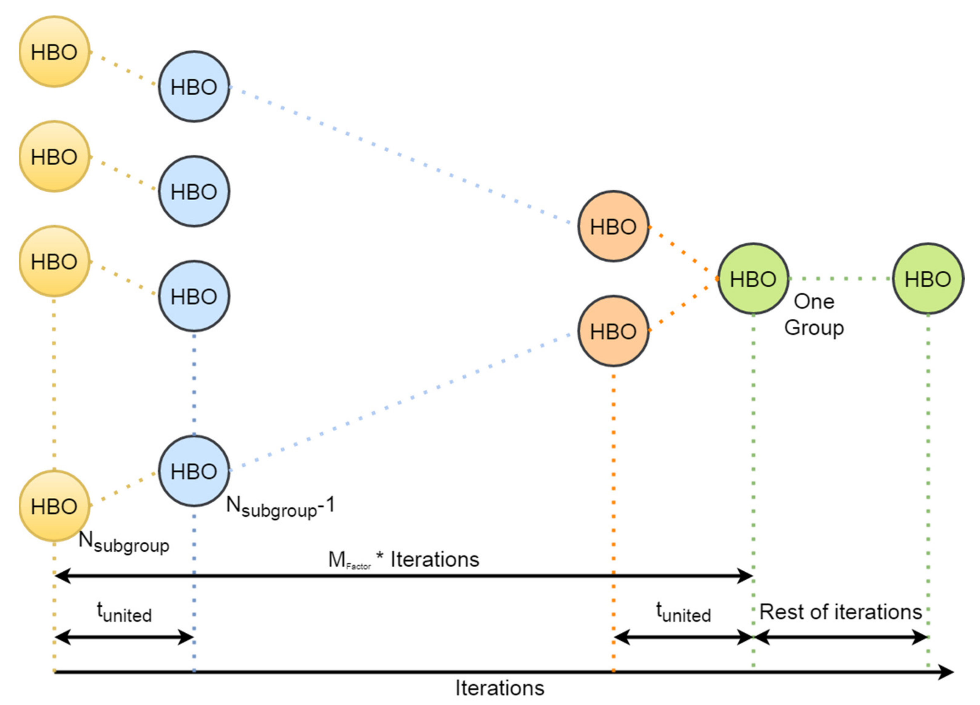
Collaborative multi-population is a term that aims to introduce the SBO. This term is based on dividing the population into subgroups. This step is useful to increase its exploration performance.
As presented in SBO, which is a collaborative multi-population framework utilized by TLBO, the proposed modified algorithm is based on its original idea, which gives it the capability to increase its exploration performance [16].
This research work suggests a novel idea, which is about the collection of sub-groups into one main group after exploration is exploited. This idea improved the exploitation part by the search for an optimal solution with all populations of sub-groups. This idea balances both optimization algorithms performances exploration and exploitation. This balance is conducted with a new factor called M f a c t o r .
There are many challenges for this idea; one of them is determining of the M f a c t o r , which depends on the user’s experience to face the problem of balance between exploitation and exploration, and the other one is about how to determine the subgroups’ number. These challenges are faced with the experience of users or trial and error to have a good performance of the optimization algorithm.
HBO is presented in [17] and applied in many other engineering optimization problems, such as solar cell estimation [18], reactive power dispatch [19], Micro-grid design and sizing [20], and Proton exchange membrane fuel cell [21]. HBO solves these optimization problems with effectiveness.
There are other methods that are used to build APS, such as an environment APS based on Q-learning as in [22] and multi-agents as in [23,24].
Contributions of this paper are as follows:
  • The proposed algorithm’s response and convergence characteristics are improved by modifying the original HBO algorithm. There are three main points that were modified: subgroups were divided and then united, traveler agents were placed between subgroups, and an equation in the original HBO was modified. This algorithm would be useful in addressing other critical issues in other branches of the power system, such as microgrid, DG sizing, load frequency control, and solar cell parameter estimation.
  • As a solution to the DG impact, an adaptive protection scheme was designed based on HBO and MHBO. That APS was used to coordinate both DOCRs and distance relays. In addition to the impact of DGs, the effect of distance relays complicates this co-ordination problem in the DOCR’s coordination process.
  • To verify the effectiveness of the proposed protection system, it was tested on IEEE 8-bus and IEEE 14-bus distribution networks, taking into account the effect of DG on/off states.
The following is the rest of the paper: the coordination problem and its mathematical modeling are presented in Section 2. The proposed protection scheme is presented in Section 3. The performance of HBO and MHBO with IEEE 8-bus and IEEE 14-bus distribution networks to solve the coordination problem is then presented in Section 4. Finally, Section 5 has the conclusions.

2. The Mathematical Modelling of Coordination Problem

The primary goal of this paper is to achieve the best possible coordination of DOCRs and distance relays. The objective function (OF) is the total operation times of the DOCRs at both near (TNear) and far (TFar) ends, as well as the second time zone of the distance relays (TZ2). That OF is the shortest total operation times as described in [1]:
O F = m i n i = 1 n T N e a r i + i = 1 n T F a r i + i = 1 n T Z 2 i + F P e n
The international electro-technical commission (IEC) standard presents the standard time inverse of DOCRs characteristics by the following equation [2]:
T i = T D S i I f I p i β γ  
where Ti is the relay’s operation time of DOCRs for ith relay, TDS is the relay’s time dial setting, and Ip is the relay’s pickup current. The other constants α,   β , and γ have values of 0.14, 0.02, and 1, respectively [25].

2.1. Problem’s Limiters

The maximum operation time (Tmax) is the primary limitation of any protection relay. In order to save the components of the power system from damage, this time should not exceed 2 s [26].
Relay’s settings are limited with minimum and maximum values for each setting, as shown in the following equations [27]:
T D S m i n T D S     T D S m a x ,
I p m i n I p     I p m a x
T Z 2 m i n   T Z 2     T Z 2 m a x  

2.2. The Problem’s Constraints

Through the constraints between the primary and backup pair of DOCRs, as well as between the pair of DOCRs and distance relays at both ends, the proposed optimization problem becomes a higher constraint problem. These constraints are used to prevent miscoordination, which can occur when protection relays fail.
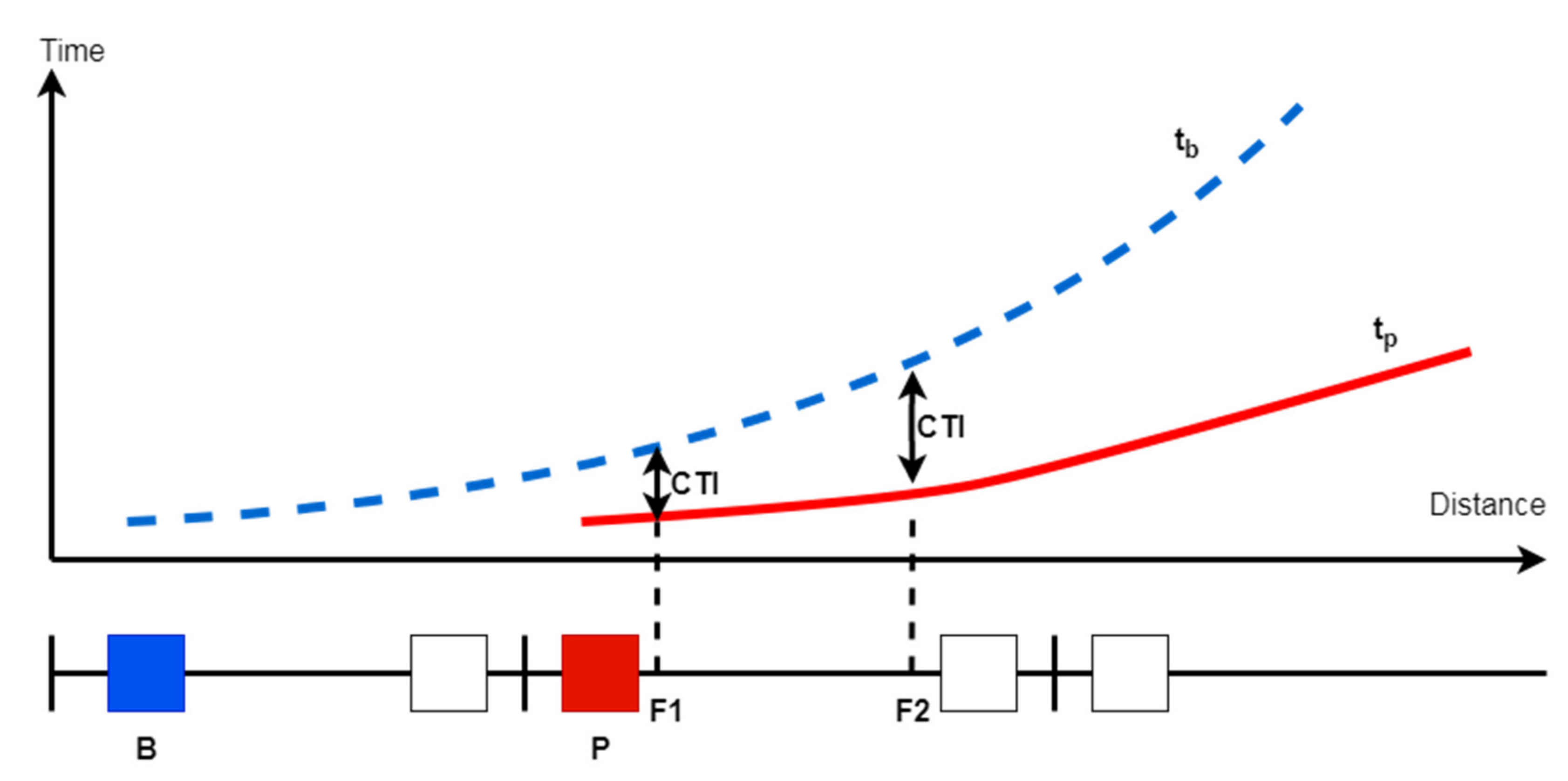
As shown in Figure 1, the relationship between DOCRs pair relays must deal with the backup relay ( t b ), which operates with a delay time on the primary relay ( t p ). This period of delay time is referred to as the coordination time interval (CTI). The CTI value is determined by the type of protection relays. The CTI value for electromagnetic relays must be greater than 0.3 s, while digital relays must be greater than 0.2 s [1]. In this research, digital relays are used. These constraints are depicted in the following equations [27,28]:
t b F 1 t p F 1 > C T I
t b F 2 t p F 2 > C T I
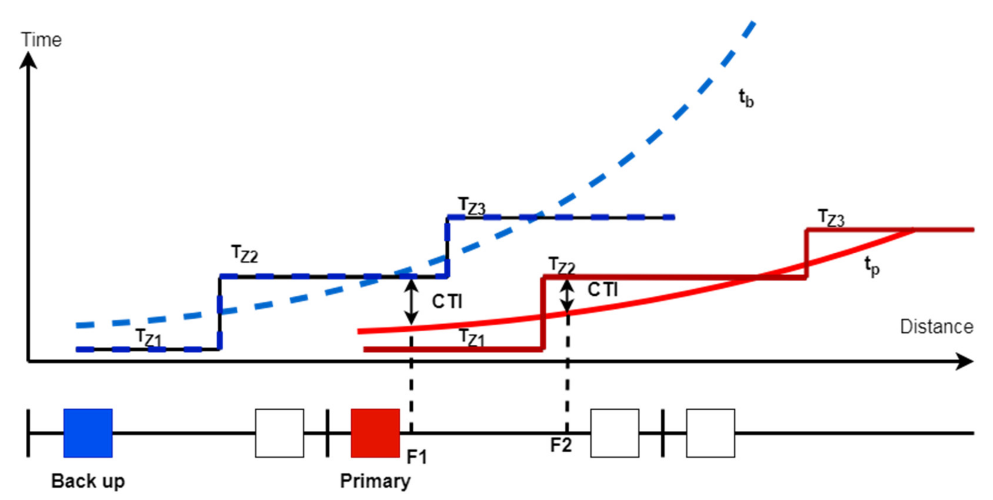
Figure 2 depicts the relationship between DOCRs and distance pair relays. At the near end, the backup distance relay liaises with the primary DOCRs relay, and TZ2b must delay t p F 1 with the CTI as described in Equation (8). While Equation (9) describes the distance and DOCRs relationship at the far end. The second zone of the primary distance relay (TZ2p) must delay the primary DOCRs operation time ( t p F 1 ) with CTI at the far end [27].
T Z 2 b t p F 1 > C T I
T Z 2 p t p F 2 > C T I
Based on the operation time of the primary relay at near and far ends. The relationship is developed to specify the minimum value of the distance relay’s second zone. As shown in Equation (10), the maximum value of these equations is used as the time for the specific second zone of distance relay. This point contributes to the reduction of the penalty and constraints [1].
T Z 2 = m a x T Z 2 b , T Z 2 p
For eliminating miscoordination between pairs relays, as recommended, the penalty function is developed as in the following equation [29]:
F p e n = μ 1 i f   T b a c k u p T p r i m a r y < C T I 0 i f   T b a c k u p T p r i m a r y C T I  
where μ is the penalty function‘s weighting factor.
When there is a miscoordination between relays pair, Fpen extends the total time of OF. As a result, the optimization algorithm tunes the relays setting parameters to reduce the size of OF to eliminate the miscoordination.

3. The Proposed Protection Scheme

3.1. Adaptive Protection Scheme (APS)

The proposed scheme in this paper is developed based on the optimal solutions obtained through the use of optimization algorithms. In addition, the HBO algorithm was used to evaluate the optimal solutions. Moreover, it is modified to improve its convergence characteristics and its ability to find better optimization solutions.
Figure 3 depicts the flow diagram of APS while taking into account the impact of DG. The obtained data from supervisory control and data acquisition (SCADA) was optimized using the centralized processing server. These data will be generated by the proposed algorithms in the APS to reset the DOCRs and distance relays. The main points of the proposed APS flow chart can be described as follows:
  • The first point defines the actual topology of the distribution network, specifically the location, state, and size of DGs. Examine the distribution network topology for any changes. If nothing changes, the APS keeps with current protection relays settings. If the topology changes, the APS proceeds to the next point.
  • In the second point, the APS calculates short circuit currents through CBs. For this mission, ETAP is used. Then, APS test the current relay settings’ ability to save the protection system without losing the coordination of protection relays. If the current settings of the relays are not able to protect the distribution network, the APS moves to the next point. Otherwise, APS returns to the previous step.
  • In the third point, APS calls up the proposed optimization algorithm. The algorithm will seek the optimal solution that is suitable for covering changes in the distribution network while avoiding miscoordination. Finally, the APS reports the best solution for protection relay settings and sends it via ICT to the network operator or the intelligent electronic devices (IEDs) [30].

3.2. Original Heap-Based Optimization Algorithm

HBO is a novel metaheuristic algorithm, which is categorized as a human-based algorithm. HBO simulates the corporate rank hierarchy (CRH) in a very distinctive style. HBO is presented mathematically based on modeling three states of employee’s relationships:
  • Between the subordinates and their immediate supervisor.
  • Between colleagues
  • Self-contribution of employees
The use of the heap data structure in the CRH mapping allows for organizing the solutions in a hierarchical manner based on their fitness and the use of the arrangement in the algorithm’s position-updating process in a very specific way. The mapping of the entire concept is modeled into the following steps:
  • Modeling CRH
  • Modeling the relationship between subordinates and the immediate supervisor
  • Modeling the interaction between colleagues
  • Modeling an employee’s self-contribution to task execution.
  • Overall update of the position of search agent uses the following equation:
x i k t + 1 = x i k t ,   p p 1 B k + γ λ k B k x i k t , p 1 < p p 2 S r k + γ λ k S r k x i k t , p 2 < p p 3   &     f S r < f x i t x i k + γ λ k S r k x i k t , p 2 < p p 3   &     f S r   f x i t
where x i k t + 1 is the updated position, x i k t is the current position, B k is the parent position, S r k is the colleague position, p is a random value with in [0,1], f x i t is the fitness value of the current position, f S r is the fitness value of the colleague position, γ , λ , p 1 , p 2 , and p 3 as the following equations:
γ = 2 t   m o d   T c T 4 c  
λ k = 2 r 1
p 1 = 1 t T
p 2 = p 1 1 p 1 2
p 3 = p 2 1 p 1 2 = 1
where t is the current iteration value, T is the total iteration number, r is a random value with in [0,1], and C as the following equation:
C = T / 25

3.3. Modified HBO Algorithm

The modified part suggests three main points to improve the exploration and exploitation performance of the original algorithm. These points are: update Equation (14), which describes λ , establishing many small companies then united in one big company, and traveling agents between companies.

3.3.1. The First Point: Developing λ Factor

This point is about developing the exploitation performance of the original algorithm. This point deals with the λ factor to modified by adding a term to connect λ with the iteration number as indicated in the following equation:
λ k = 0.5 1 t T 2 r 1
This term gives the original HBO a chance to have more exploitation without effect on the exploration performance.

3.3.2. The Second Point: Sub-Group and M f a c t o r

This point is about establishing small groups from search agents, these groups use HBO as an individual unit, then they are united in bigger groups until united in one group. As shown in Figure 4. The number of subgroups ( N s u b g r o u p ) are determined by the user.
M f a c t o r is a factor used to determine the number of iterations that are necessary to begin the unity ( t u n i t e d ). As described in the following equation:
t u n i t e d = r o u n d M f a c t o r T N s u b g r o u p
In addition, M f a c t o r is determined by the user with a percentage value depending on the optimization problem in this coordination problem determined by 10% to increase the exploration performance of the HBO algorithm.
This point is very important to discover the search area adding to lose constraints, which is an important goal in an optimal problem. That point gives the algorithm all the search agents for exploitation along with other algorithm’s iterations after uniting in one company.

3.3.3. The Third Point: Travelers

In the final point, in any company there are Travelers, they move between companies, those travelers give a chance to exchange skills between sub-groups. Travelers are unpredictable, thus, they are chosen randomly. The number of travelers can be limited by the user as a percentage value from the sub-group members.

4. Results and Discussion

In this research work, APS used both HBO and MHBO to tune optimal relay coordination problem in all cases of test systems. These relay’s settings were TDS, Ip, and TZ2. DOCRs have normal characteristic values such as 0.14, 0.02, and 1.0 for α, β, and γ constants, respectively. In addition to the maximum and minimum values of TDS and PS as 1.1 s and 0.1 s for TDS and 4 and 0.5 for PS. Moreover, the maximum operating time for the primary DOCRs or distance relays was 1.5 s [27].
The test systems were IEEE 8-bus test system and IEEE 14-bus distribution network. The test system’s cases were the normal grid topological, and the other was a switch on the DGs on the grid. Optimal settings were used to reduce the operation time of relays and also for passing the system’s constraints in both the near end and far end. These constraints were between DOCRs and Distance relays. These protection devices were assumed as digital relays with CTI equal to 0.2 s [1].
The proposed algorithms that were used in this paper have a population, max iteration, maximum travel percentage, society, and M f a c t o r with values 840, 1000, 10%, 8, and 10%, respectively. MATLAB R2016a was used to run these algorithms. While ETAP 12.6.0 was used for the validation of the relay’s operation times and the calculated 3 phase fault currents.

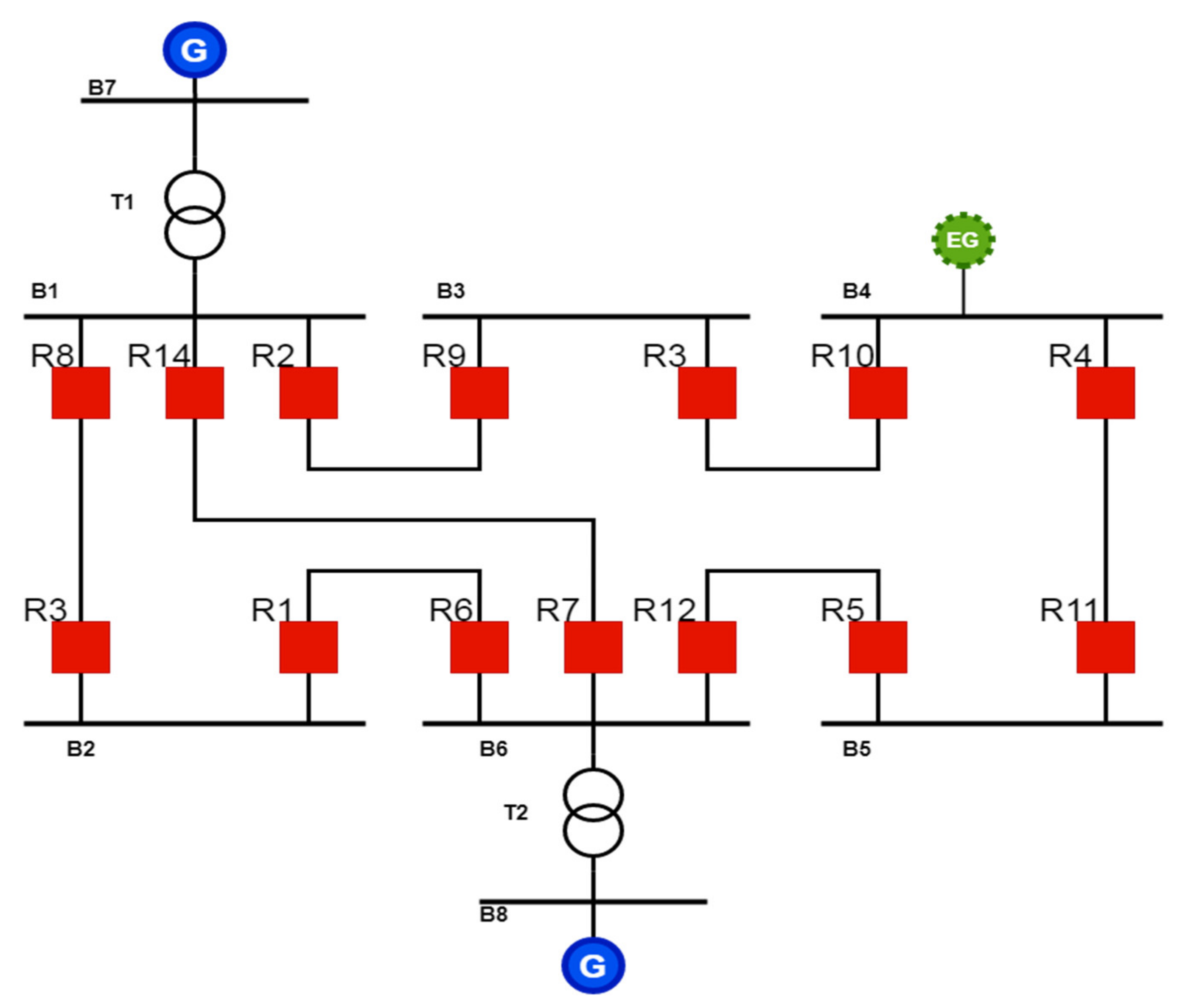
4.1. Test System I: IEEE 8-Bus Test System

The IEEE 8-bus test system, shown in Figure 5, consists of 7 transmission lines connected between 8 buses and feeds 4 loads from two synchronous generators. These generators feed the network by power transforms T1, and T2. This configuration will be considered as the normal topology. In order to investigate the performance of the proposed APS for relays coordination, an external 400 MW microgrid (EG) will be integrated into the system at the fourth bus (B4). The test system has 14 CB, each transmission line has two circuit breakers (CBs), that are activated by the APS. Furthermore, the protection settings are allowed to be changed according to the change of the grid topology [31].
The optimization problem aims at tuning 42 design variables. In addition to 40 constraints between DOCRs and distance relays, and 32 constraints between DOCRs in normal grid topology, while in the other case is 34 constraints. This makes that optimization problem a highly constrained problem adding to it is a non-linear problem. Each variable design is limited with maximum and minimum limiters.
Three-phase fault currents and CT values are extracted from [1].
The optimal values of variables designed for protective relays on the normal grid topology using MHBO and HBO are listed in Table 1. Additional to the other case about the external grid is the switching on of the optimal solution. Then Table 2 shows that the proposed algorithm’s optimal solution passed the constraints between DOCRs, and between DOCRs and Distance. Whiles constraints pass in both between DOCRs, and between DOCRs and Distance, as shown in Table 3.
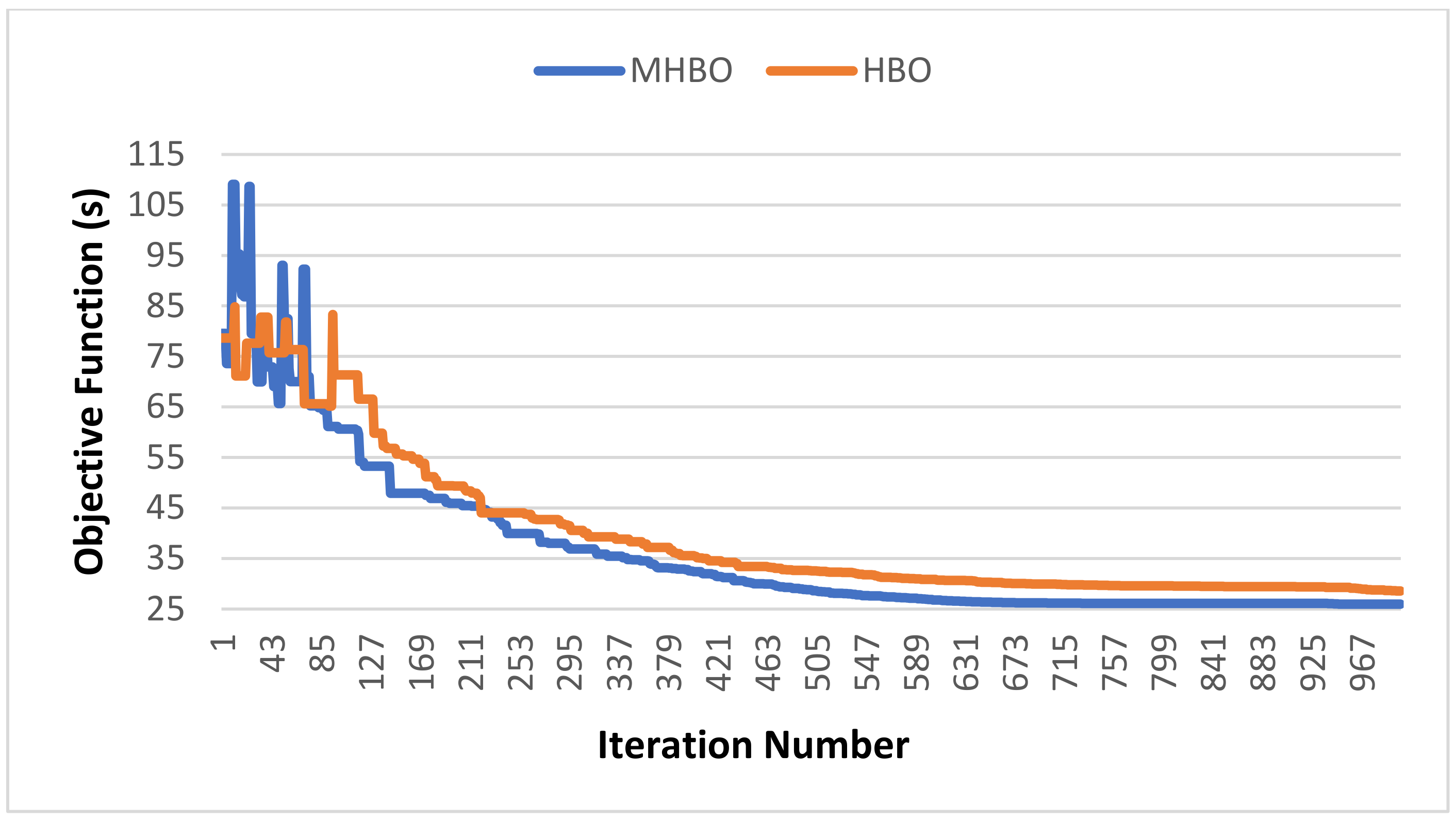
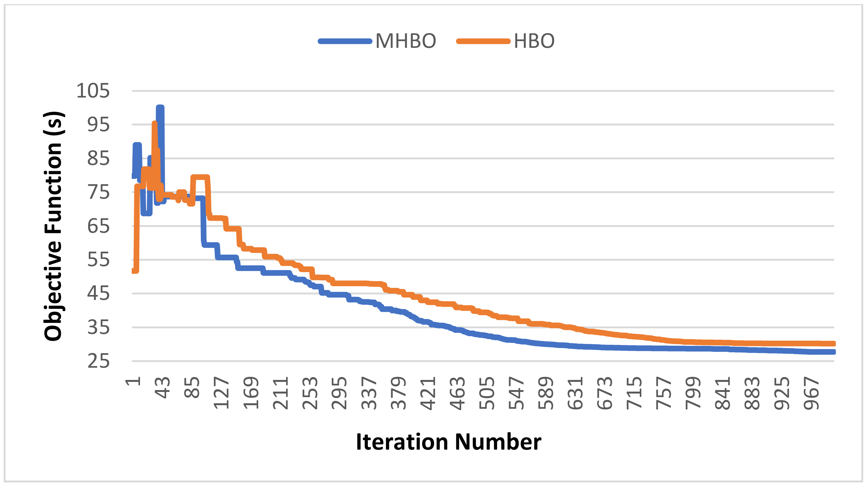
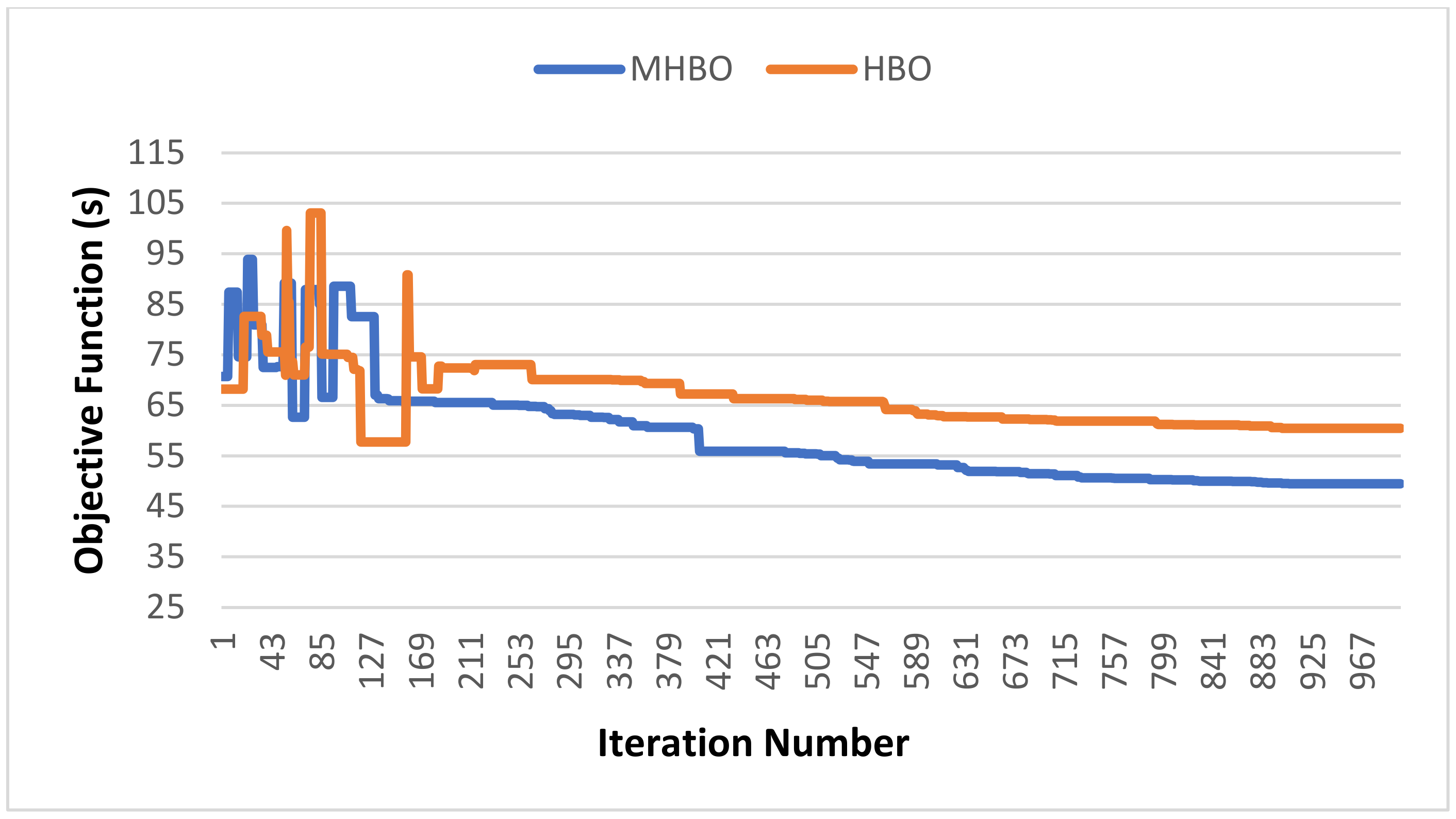
Figure 6 shows the convergence characteristics curves of HBO and MHBO in the case of the original case of the grid, whiles 
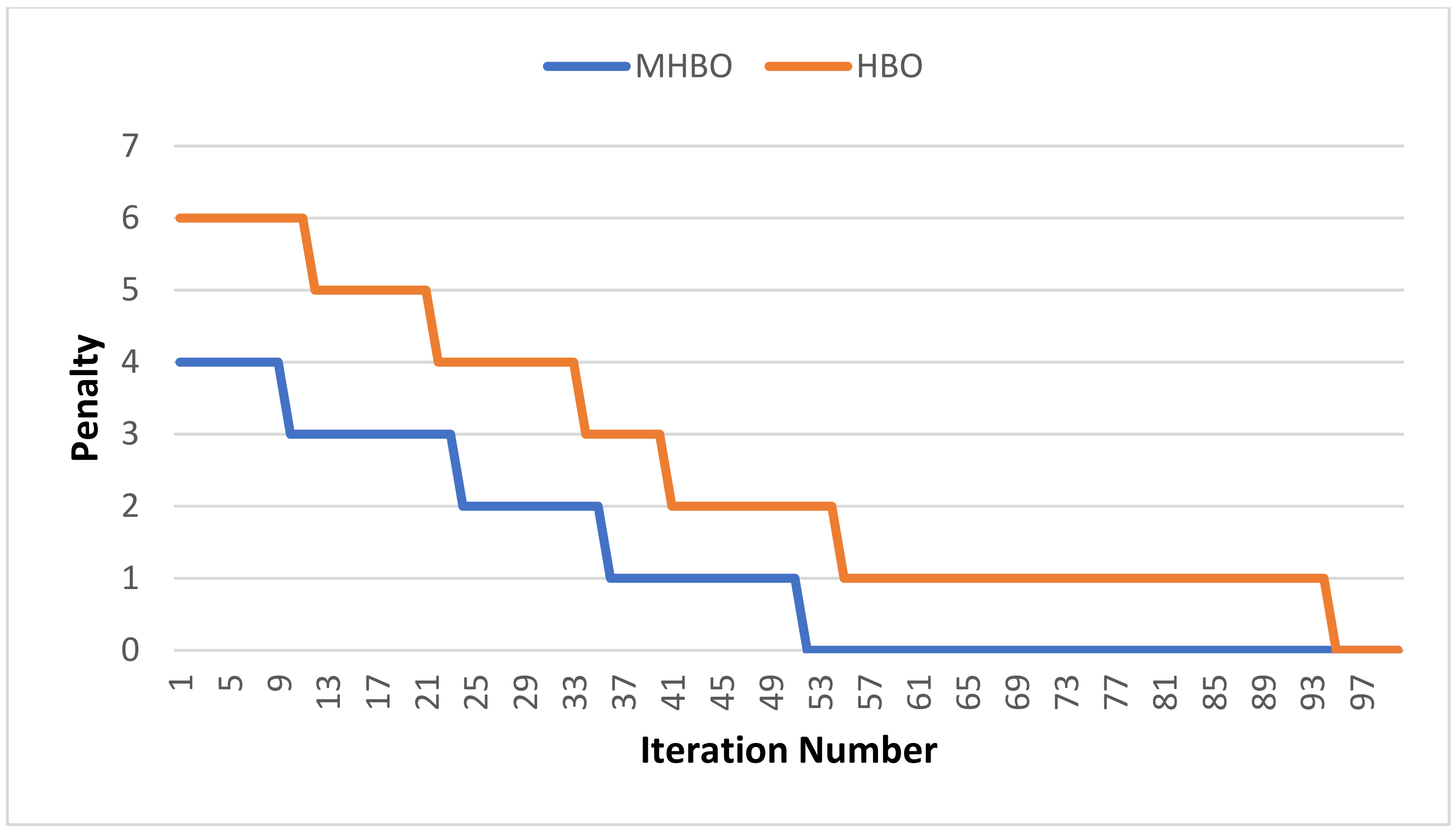
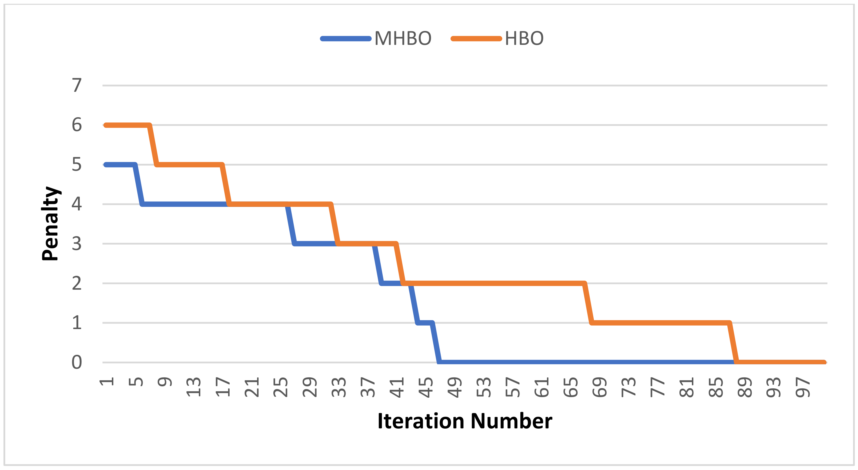
Figure 7 deals with the other case. The penalty is shown in Figure 8. This is for HBO and MHBO in the original case of the grid, while in the other case, the penalty is shown in Figure 9.
Previous results proved the ability of the proposed APS to coordinate protection relays at IEEE 8-bus with reliability and suitable settings. In addition to avoiding miscoordination within limiters. APS has a more effective performance based on the MHBO than based on HBO. That is shown by the convergence characteristics. The convergence of MHBO is faster and better than the original HBO. In addition, the modified algorithm avoids constraints faster, as presented by the penalty meter. That proved the ability of the modified algorithm to increase its exploitation and exploration performances.

4.2. Test System II: IEEE 14-Bus Distribution Network

The IEEE 14-bus distribution network is a downstream section of the IEEE 14-bus test system, as shown in Figure 10 [32]. This distribution network has 16 CBs to save its transmission lines, adding it is developed by adding 2 DGs, which are connected at the fifth bus and seventh bus. These DGs are synchronous generators with 5 MVA power rated and power factor of 0.9 lagging. That developed network is discussed in [33].
Three phases short circuit values and CT values are shown as in [28,32].
In this distribution network, protective relays have 48 variables design, which is required to be tuned by APS in both cases. The normal grid topology and the 2 DGs are switched on. Those variables design limited the minimum and maximum limiters. In addition to that, the coordination problem is constrained by 41 between DOCRs and 44 between DOCRs, and Distance relays. These constraints formed in the near end and the far end.
Optimal values tuned using HBO and MHBO are tabulated in Table 4. They are in cases of the original topology of the grid and after the DGs are switched on. Table 5 shows that the APS passed the constraints between DOCRs and between DOCRs and Distance relays, respectively. The APS passed constraints between DOCRs, and between DOCRs, and distance relays, as shown in Table 6.
The convergence characteristics curves of HBO and MHBO are shown in Figure 11 and 
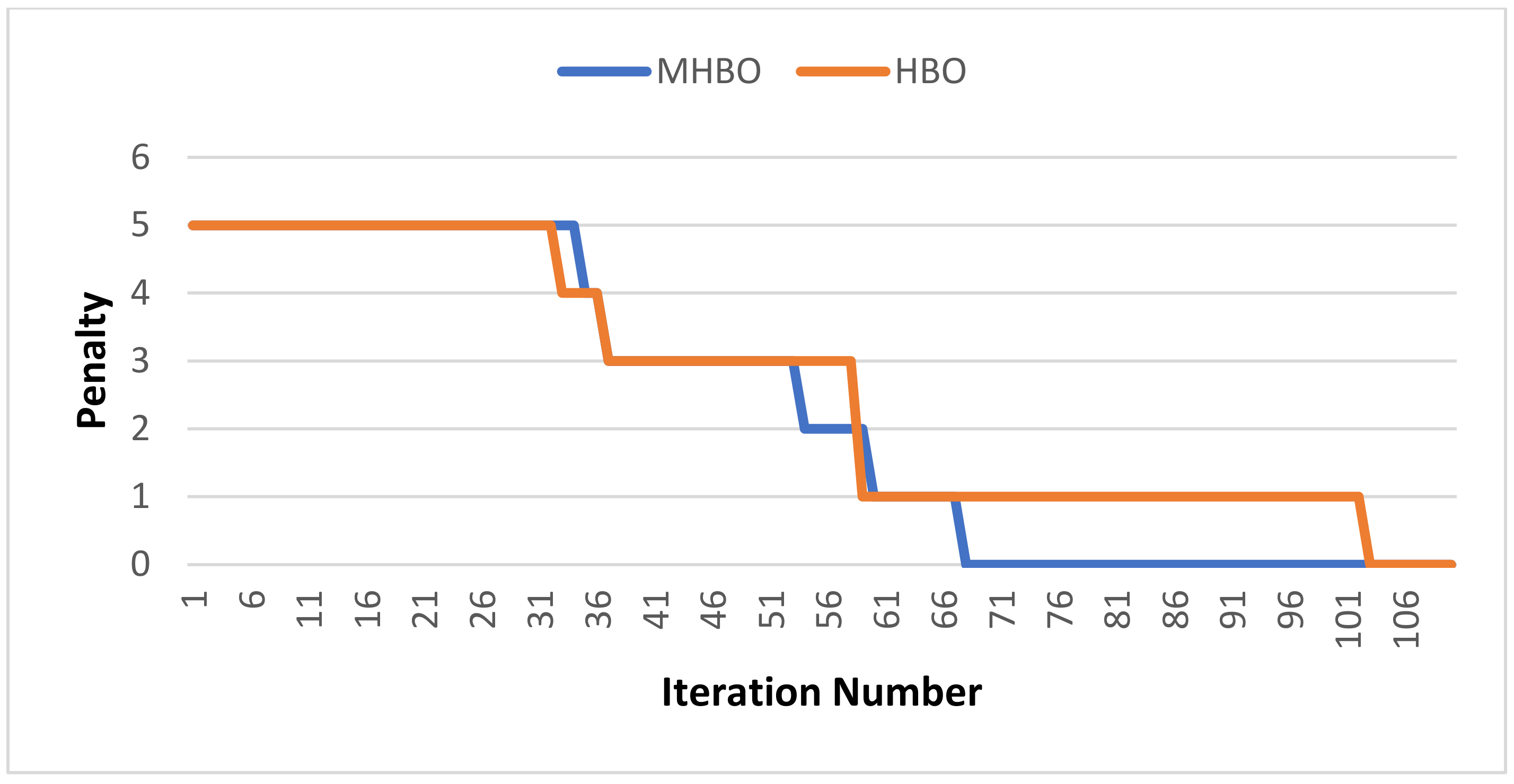
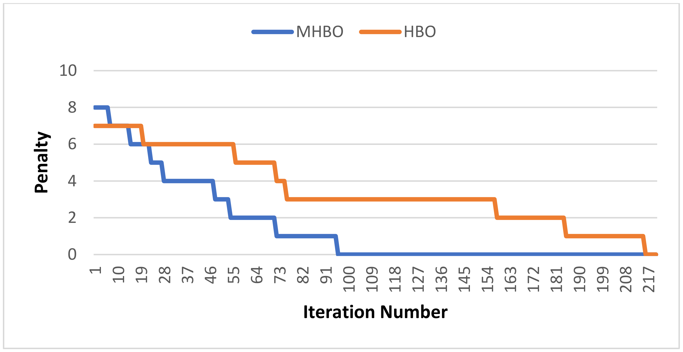
Figure 12, which occurred in the traditional grid and after switching DGs on, respectively. The penalty of HBO and MHBO are shown in Figure 13 and Figure 14 to present the penalty in the traditional grid and the other case, respectively.
As demonstrated through the results and performance of the proposed APS in the coordination process of protection relays at the IEEE 14-bus distribution network, the following can be stated: APS tuned settings of distance and DOCRs with suitable settings, the protection system has reliability, effectiveness, and fast performance. APS based on MHBO has better convergence characteristics and better solutions than APS based on HBO. MHBO has better convergence and needs less iteration to avoid miscoordination based on penalty than HBO. This proves that MHBO improved its exploitation and exploration performance.

4.3. Verification of MHBO Using ETAP 12.6.0

Results tuned by the MHBO algorithm are verified using the ETAP. All cases developed based on three-phase faults happened in both the near end and the far end of the following transmission lines:
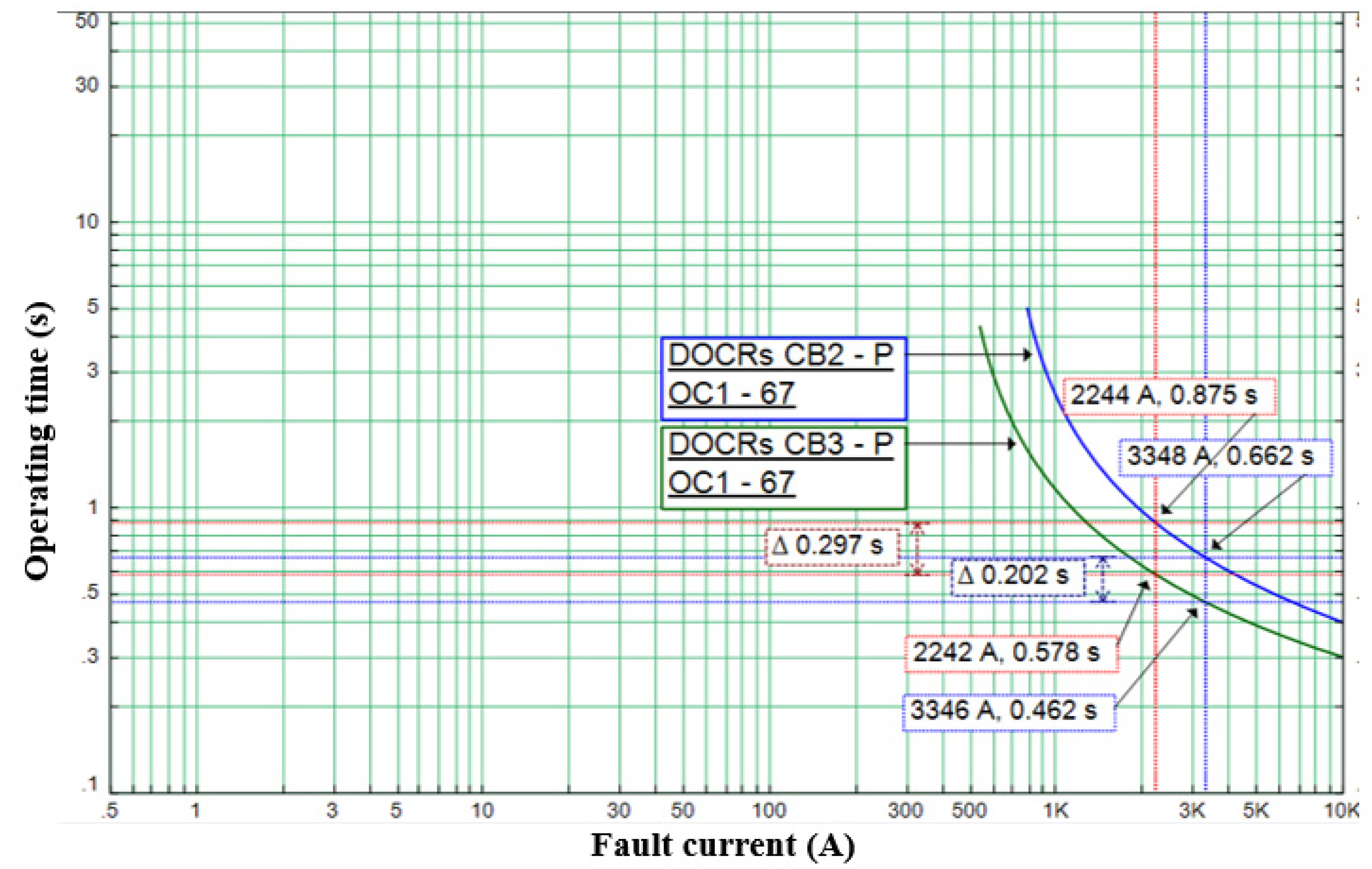
The first case is at the transmission line between the 3rd and 4th bus-bars. As shown in Figure 15, ETAP’s simulation is shown at the near end, operation times of pair relays 3 and 2 operate at 0.662 s, and 0.462 s, respectively, while at the far end, operating times are 0.875 s and 0.578, respectively.
ETAP’s simulation is also conducted, however, in this case, at the transmission line between 5th and 6th bus-bars. As shown in Figure 16, in this case, the operations time of pair relays 5 and 4 at the near end are 0.295 s and 0.496 s, respectively, while at the far end are 0.611 s and 1.98 s, respectively.
For the last case, the simulation is as shown in Figure 17, which is conducted at the transmission line between the 1st and 3rd bus-bars. That figure shows the operation times of pair relays 9 and 10 at the near end, which is 0.295 s and 0.494 s, respectively, whereas at the far end, they are 2.32 s and 0.611 s, respectively.
Simulations confirm that APS based on MHBO has the ability to coordinate protection relays without miscoordination between DOCRs since all CTI is equal or more than 0.2 s, and the operation times are within limits.

4.4. Statistical Results

Table 7 provides the statistical analysis of the proposed algorithms for HBO and MHBO. Each algorithm has a maximum value (Max), minimum value (Min), Mean of runs, and standard deviation (STD) of runs. The number of runs was 15 for each algorithm at each test case. These results proved that MHBO had better statistic parameters than HBO. Moreover, STD shows MHBO was more stable than HBO in all test cases. Therefore, MHBO has the ability to keep stable performance with more complex distribution networks. However, HBO has more variance with more complex distribution networks.

4.5. Comparison Study

In this paper, APS is designed to coordinate DOCRs and distance relays. That novel issue was discussed in [1] and presented APS based on the SBO algorithm and its modification. Those techniques are recent techniques and have effective performances to design APS. Table 8 presents the APS’s results based on different optimization algorithms.
From this table, MHBO has the best results in all test cases. At the same time, HBO has better solutions than MSBO and SBO in two cases. These cases are the IEEE 8-bus test system with EG switched ON case, and the normal IEEE 14-bus distribution network case and the other test cases HBO does not present an impact to the design of APS.

4.6. Applying APS in Real Power System

APS requires many hardware components to be applied in the real power system [34]. Those hardware components are the following:
  • Protection relays include microprocessors.
  • A central computer system to collect data from sensors, estimate DGs states, and apply algorithm to tune relay’s setting.
  • A communication infrastructure to connect protection relays with the central computer system.

5. Conclusions

In this research work, APS is proposed based on MHBO. The developed algorithm succeeded to overcome challenges in the area of coordination problem between protection relays. The simulated results show that APS has the ability to coordinate DOCRs and distance relays with suitable settings to solve the problem of distribution networks equipped with DGs. APS allows the power system to investigate both distance and DOCRs benefits with increased reliability. The modified algorithm (MHBO) makes APS more effective in resolving the coordination, as it has better convergence characteristics curves and optimal values than other previously suggested algorithms. The proposed algorithm reduces the relays time settings below the maximum operation times and within allowed limits. Finally, primary and backup relays are set without miscoordination at any end.
MHBO is an effective optimization algorithm but limited with the experience of users to identify its special parameters such as M factor, t u n i t e d , and N s u b g r o u p . They are depended on the optimization problem.
For future works, those parameters will be used to modify other optimization algorithms. In Addition, MHBO will be used with other optimization problems. Moreover, we will try to design APS with better performance and characteristics to deal with the impact of DG, and tested in real large-scales networks.

Author Contributions

Conceptualization, S.K., E.M.A. and E.B.A.; methodology, M.A., S.K., E.M.A.; software, M.A. and E.B.A.; validation, M.A., S.K. and E.M.A.; formal analysis, M.A. and E.B.A.; investigation, S.K. and E.M.A.; resources, M.A. and S.K.; data curation, S.K. and E.M.A.; writing—original draft preparation, M.A., S.K., E.M.A. and E.B.A.; writing—review and editing, S.K. and E.M.A.; visualization, S.K. and E.B.A.; supervision, S.K. and E.M.A.; project administration, S.K.; funding acquisition, S.K. and E.M.A. All authors have read and agreed to the published version of the manuscript.

Funding

This work was funded by the Deanship of Scientific Research at Jouf University under grant No (DSR-2021-02-0306).

Conflicts of Interest

The authors declare no conflict of interest.

Abbreviations

AcronymName
APSadaptive protection scheme
HBOheap- based optimization
MHBOmodified heap- based optimization
DOCRsdirectional overcurrent relays
DGsdistributed generators
OCRsOvercurent relays
ICTinformation and communication technologies
PSOparticle swarm optimization
GAgenetic algorithm
DEAdifferential evolution algorithm
ACOant colony optimization
FAfirefly algorithm
GSAgravitational search algorithm
MRFOmanta ray foraging optimization
HHOhybrid Harris hawks optimization
SBOschool-based optimization algorithm
MSBOmodified school-based optimization algorithm
IECThe international electro-technical commission
SCADAsupervisory control and data acquisition
IEDsintelligent electronic devices
CRHthe corporate rank hierarchy
EGExternal grid
NotationName
OFThe objective function
TNeartotal operation times of the DOCRs at near end
TFartotal operation times of the DOCRs at far end
TZ2the second time zone of the distance relays
Tithe relay’s operation time of DOCRs for ith relay
TDSthe relay’s time dial setting
Ipthe relay’s pickup current
α, β , and γ Constant values
TmaxThe maximum operation time
t b the backup relay’s time
t p the primary relay’s time
CTIthe coordination time interval
F p e n the penalty function
μ the penalty function‘s weighting factor.
x i k t + 1 the updated position
x i k t the current position
B k the parent position
S r k the colleague position
p a random value with in [0,1]
f x i t the fitness value of current position
f S r the fitness value of the colleague position
γ , λ , C, T, p 1 , p 2 , and p 3 Are special parameters of HBO algorithm
N s u b g r o u p The number of subgroups
t u n i t e d the number of iterations that are necessary to begin the unity

References

  1. Abdelhamid, M.; Kamel, S.; Korashy, A.; Tostado-Véliz, M.; Banakhr, F.A.; Mosaad, M.I. An Adaptive Protection Scheme for Coordination of Distance and Directional Overcurrent Relays in Distribution Systems Based on a Modified School-Based Optimizer. Electronics 2021, 10, 2628. [Google Scholar] [CrossRef]
  2. Abdelhamid, M.; Kamel, S.; Selim, A.; AMohamed, M.; Amed, M.; Elsayed, S. Development Of Bonobo Algorithm And Its Application For Optimal Coordination Of Directional Overcurrent Relays in Power Systems. DYNA 2021, 96, 492–497. [Google Scholar] [CrossRef]
  3. Damchi, Y.; Sadeh, J.; Rajabi Mashhadi, H. Considering pilot protection in the optimal coordination of distance and directional overcurrent relays. Iran. J. Electr. Electron. Eng. 2015, 11, 154–164. [Google Scholar]
  4. Khederzadeh, M. Back-up protection of distance relay second zone by directional overcurrent relays with combined curves. In Proceedings of the 2006 IEEE Power Engineering Society General Meeting, Montreal, QC, Canada, 18–22 June 2006. [Google Scholar] [CrossRef]
  5. Perez, L.G.; Urdaneta, A.J. Optimal computation of distance relays second zone timing in a mixed protection scheme with directional overcurrent relays. IEEE Trans. Power Deliv. 2001, 16, 385–388. [Google Scholar] [CrossRef]
  6. Sarwagya, K.; Nayak, P.K.; Ranjan, S. Optimal coordination of directional overcurrent relays in complex distribution networks using sine cosine algorithm. Electr. Power Syst. Res. 2020, 187, 106435. [Google Scholar] [CrossRef]
  7. Akdag, O.; Yeroglu, C. Optimal directional overcurrent relay coordination using MRFO algorithm: A case study of adaptive protection of the distribution network of the Hatay province of Turkey. Electr. Power Syst. Res. 2021, 192, 106998. [Google Scholar] [CrossRef]
  8. Ates, Y.; Uzunoglu, M.; Karakas, A.; Boynuegri, A.R.; Nadar, A.; Dag, B. Implementation of adaptive relay coordination in distribution systems including distributed generation. J. Clean. Prod. 2016, 112, 2697–2705. [Google Scholar] [CrossRef]
  9. Vijayakumar, D.; Nema, R.K. A novel optimal setting for directional over current relay coordination using particle swarm optimization. Int. J. Electr. Power Energy Syst. Eng. 2008, 1, 1–6. [Google Scholar]
  10. Singh, D.K.; Gupta, S. Optimal coordination of directional overcurrent relays: A genetic algorithm approach. In Proceedings of the 2012 IEEE Students’ Conference on Electrical, Electronics and Computer Science, Bhopal, India, 1–2 March 2012; pp. 1–4. [Google Scholar]
  11. Moirangthem, J.; Krishnanand, K.R.; Dash, S.S.; Ramaswami, R. Adaptive differential evolution algorithm for solving non-linear coordination problem of directional overcurrent relays. IET Gener. Transm. Distrib. 2013, 7, 329–336. [Google Scholar] [CrossRef]
  12. Shih, M.Y.; Salazar, C.A.C.; Enŕiquez, A.C. Adaptive directional overcurrent relay coordination using ant colony optimisation. IET Gener. Transm. Distrib. 2015, 9, 2040–2049. [Google Scholar] [CrossRef]
  13. Tjahjono, A.; Anggriawan, D.O.; Faizin, A.K.; Priyadi, A.; Pujiantara, M.; Taufik, T.; Purnomo, M.H. Adaptive modified firefly algorithm for optimal coordination of overcurrent relays. IET Gener. Transm. Distrib. 2017, 11, 2575–2585. [Google Scholar] [CrossRef]
  14. Chawla, A.; Bhalja, B.R.; Panigrahi, B.K.; Singh, M. Gravitational search based algorithm for optimal coordination of directional overcurrent relays using user defined characteristic. Electr. Power Compon. Syst. 2018, 46, 43–55. [Google Scholar] [CrossRef]
  15. ElSayed, S.K.; Elattar, E.E. Hybrid Harris hawks optimization with sequential quadratic programming for optimal coordination of directional overcurrent relays incorporating distributed generation. Alex. Eng. J. 2021, 60, 2421–2433. [Google Scholar] [CrossRef]
  16. Degertekin, S.O.; Tutar, H.; Lamberti, L. School-based optimization for performance-based optimum seismic design of steel frames. Eng. Comput. 2021, 37, 3283–3297. [Google Scholar] [CrossRef]
  17. Askari, Q.; Saeed, M.; Younas, I. Heap-based optimizer inspired by corporate rank hierarchy for global optimization. Expert Syst. Appl. 2020, 161, 113702. [Google Scholar] [CrossRef]
  18. Rizk-Allah, R.M.; El-Fergany, A.A. Emended heap-based optimizer for characterizing performance of industrial solar generating units using triple-diode model. Energy 2021, 237, 121561. [Google Scholar] [CrossRef]
  19. Elsayed, S.K.; Kamel, S.; Selim, A.; Ahmed, M. An Improved Heap-Based Optimizer for Optimal Reactive Power Dispatch. IEEE Access 2021, 9, 58319–58336. [Google Scholar] [CrossRef]
  20. Kharrich, M.; Kamel, S.; Hassan, M.H.; ElSayed, S.K.; Taha, I.B.M. An Improved Heap-Based Optimizer for Optimal Design of a Hybrid Microgrid Considering Reliability and Availability Constraints. Sustainability 2021, 13, 10419. [Google Scholar] [CrossRef]
  21. Abdel-Basset, M.; Mohamed, R.; Elhoseny, M.; Chakrabortty, R.K.; Ryan, M.J. An efficient heap-based optimization algorithm for parameters identification of proton exchange membrane fuel cells model: Analysis and case studies. Int. J. Hydrog. Energy 2021, 46, 11908–11925. [Google Scholar] [CrossRef]
  22. Cui, Q.; Weng, Y. An environment-adaptive protection scheme with long-term reward for distribution networks. Int. J. Electr. Power Energy Syst. 2021, 124, 106350. [Google Scholar] [CrossRef]
  23. Dos Reis, F.B.; Pinto, J.O.C.P.; dos Reis, F.S.; Issicaba, D.; Rolim, J.G. Multi-agent dual strategy based adaptive protection for microgrids. Sustain. Energy Grids Netw. 2021, 27, 100501. [Google Scholar] [CrossRef]
  24. Sampaio, F.C.; Leão, R.P.S.; Sampaio, R.F.; Melo, L.S.; Barroso, G.C. A multi-agent-based integrated self-healing and adaptive protection system for power distribution systems with distributed generation. Electr. Power Syst. Res. 2020, 188, 106525. [Google Scholar] [CrossRef]
  25. Abdelhamid, M.; Kamel, S.; Mohamed, M.A.; Aljohani, M.; Rahmann, C.; Mosaad, M.I. Political Optimization Algorithm for Optimal Coordination of Directional Overcurrent Relays. In Proceedings of the 2020 IEEE Electric Power and Energy Conference (EPEC), Edmonton, AB, Canada, 9–10 November 2020; pp. 1–7. [Google Scholar]
  26. Abdelhamid, M.; Kamel, S.; Mohamed, M.A.; Rahmann, C. An Effective Approach for Optimal Coordination of Directional Overcurrent Relays Based on Artificial Ecosystem Optimizer. In Proceedings of the 2021 IEEE International Conference on Automation/XXIV Congress of the Chilean Association of Automatic Control (ICA-ACCA), Valparaíso, Chile, 22–26 March 2021; pp. 1–6. [Google Scholar]
  27. Rivas, A.E.L.; Pareja, L.A.G.; Abrão, T. Coordination of distance and directional overcurrent relays using an extended continuous domain ACO algorithm and an hybrid ACO algorithm. Electr. Power Syst. Res. 2019, 170, 259–272. [Google Scholar] [CrossRef]
  28. Rajput, V.N.; Adelnia, F.; Pandya, K.S. Optimal coordination of directional overcurrent relays using improved mathematical formulation. IET Gener. Transm. Distrib. 2018, 12, 2086–2094. [Google Scholar] [CrossRef]
  29. Mohammadi, R.; Abyaneh, H.A.; Rudsari, H.M.; Fathi, S.H.; Rastegar, H. Overcurrent relays coordination considering the priority of constraints. IEEE Trans. Power Deliv. 2011, 26, 1927–1938. [Google Scholar] [CrossRef]
  30. Shih, M.Y.; Conde, A.; Ángeles-Camacho, C.; Fernández, E.; Leonowicz, Z.; Lezama, F.; Chan, J. A two stage fault current limiter and directional overcurrent relay optimization for adaptive protection resetting using differential evolution multi-objective algorithm in presence of distributed generation. Electr. Power Syst. Res. 2021, 190, 106844. [Google Scholar] [CrossRef]
  31. Yang, M.-T.; Liu, A. Applying Hybrid PSO to Optimize Directional Overcurrent Relay Coordination in Variable Network Topologies. J. Appl. Math. 2013, 2013, 879078. [Google Scholar] [CrossRef]
  32. Christie, R. Power systems test case archive. Electr. Eng. Dept. Univ. Washingt. 2000. Available online: https://www2.ee.washington.edu/research/pstca (accessed on 20 November 2021).
  33. Saleh, K.A.; Zeineldin, H.H.; Al-Hinai, A.; El-Saadany, E.F. Optimal coordination of directional overcurrent relays using a new time–current–voltage characteristic. IEEE Trans. Power Deliv. 2014, 30, 537–544. [Google Scholar] [CrossRef]
  34. Ates, Y.; Boynuegri, A.R.; Uzunoglu, M.; Nadar, A.; Yumurtacı, R.; Erdinc, O.; Paterakis, N.G.; Catalão, J.P.S. Adaptive Protection Scheme for a Distribution System Considering Grid-Connected and Islanded Modes of Operation. Energies 2016, 9, 378. [Google Scholar] [CrossRef]
Figure 1. The relationship between DOCRs pair relays.
Mathematics 10 00419 g001
Figure 2. The relationship between Distance and DOCRs pair relays.
Mathematics 10 00419 g002
Figure 3. The Flow diagram of the proposed APS.
Mathematics 10 00419 g003
Figure 4. The diagram of united subgroups idea.
Mathematics 10 00419 g004
Figure 5. The single line diagram of IEEE8-bus test system.
Mathematics 10 00419 g005
Figure 6. HBO and MHBO convergence characteristics in the traditional case of IEEE 8-bus.
Mathematics 10 00419 g006
Figure 7. HBO and MHBO convergence characteristics in case the external grid switching on of IEEE 8-bus.
Mathematics 10 00419 g007
Figure 8. HBO and MHBO’s penalty of the traditional IEEE 8-bus test system’s grid.
Mathematics 10 00419 g008
Figure 9. HBO and MHBO’s Penalty of the IEEE 8-bus test system with external grid switching on.
Mathematics 10 00419 g009
Figure 10. The single line diagram of 14-bus distribution network.
Mathematics 10 00419 g010
Figure 11. HBO and MHBO’s convergence characteristics in traditional grid of IEEE 14-bus distribution network.
Mathematics 10 00419 g011
Figure 12. HBO and MHBO’s convergence characteristics with DGs switching on case of IEEE 14-bus distribution network.
Mathematics 10 00419 g012
Figure 13. HBO and MHBO’s Penalty of IEEE 14-bus distribution network’s traditional grid.
Mathematics 10 00419 g013
Figure 14. HBO and MHBO’s penalty of IEEE 14-bus distribution network with DGs switching on.
Mathematics 10 00419 g014
Figure 15. ETAP’s simulation test of pair relays (3,2).
Mathematics 10 00419 g015
Figure 16. ETAP’s simulation test of pair relays (5,4).
Mathematics 10 00419 g016
Figure 17. ETAP’s simulation test of pair relays (9,10).
Mathematics 10 00419 g017
Table 1. IEEE 8-bus test system’s relays setting.
RelayTraditional Topological GridDG Switching ON
Original HBOModified HBOOriginal HBOModified HBO
TDSIpTZ2TDSIpTZ2TDSIpTZ2TDSIpTZ2
10.207120.0000.9420.132227.6710.9150.178229.4781.0370.128308.3920.957
20.161697.2060.9060.159638.9550.8610.216585.9491.0230.187592.9340.918
30.168318.9670.7930.137436.5780.7750.32980.0000.8680.161411.6690.854
40.108338.3150.7340.114279.0300.6960.124611.7760.8260.112692.2770.822
50.100169.6300.9730.100134.2890.8120.100473.7480.9460.113380.2710.880
60.192423.0860.9110.133533.5460.7640.149773.0980.9170.143582.9070.774
70.196249.3120.9410.132426.4970.9110.240263.6561.0360.198311.1380.956
80.174456.7540.9030.154462.2920.8280.188366.3570.8140.163427.3980.775
90.100163.7390.9440.100142.4840.8460.134300.8080.8870.106378.6270.858
100.157182.7760.7180.114295.2190.6950.132591.5400.8360.109699.3630.795
110.154425.2500.8210.100712.7030.7810.128676.0780.9140.106750.8630.842
120.182592.2160.9050.175524.1870.8340.205522.1550.9190.200465.7590.863
130.221120.0000.9930.176149.6310.9160.141290.0360.9970.118328.3080.942
140.175335.1510.9920.124468.6100.9200.195338.6030.9850.155443.4960.942
OF28.60925.98330.19227.799
Table 2. IEEE 8-bus test system’s operation times of Relay’s pairs in Traditional grid by MHBO.
PairNear-EndFar-End
DOCRsD&DOCRDOCRsD&DOCR
TpTbCTITpTZ2BCTITpTbCTITpTZ2PCTI
10.3630.5640.2010.3630.7640.4010.7152.2071.4910.7150.9150.2
20.5100.7150.2050.5100.9150.4050.6613.0072.3470.6610.8610.2
30.5100.7110.2000.5100.9110.4000.6612.8992.2390.6610.8610.2
40.4600.6610.2000.4600.8610.4000.5750.8750.2990.5750.7750.2
50.3750.5750.2000.3750.7750.4000.4960.8320.3360.4960.6960.2
60.2950.4960.2010.2950.6960.4010.6121.9921.3800.6120.8120.2
70.4070.6120.2050.4070.8120.4050.564ـــــــ ـــــــ 0.5640.7640.2
80.4070.7200.3130.4070.9200.5130.564ـــــــ ـــــــ 0.5640.7640.2
90.3920.6120.2200.3920.8120.4200.711ـــــــ ـــــــ 0.7110.9110.2
100.3920.7160.3240.3920.9160.5240.711ـــــــ ـــــــ 0.7110.9110.2
110.4430.7110.2680.4430.9110.4680.628ـــــــ ـــــــ 0.6280.8280.2
120.4430.6460.2040.4430.8460.4040.628ـــــــ ـــــــ 0.6280.8280.2
130.2940.4950.2000.2940.6950.4000.6462.3271.6810.6460.8460.2
140.3790.5810.2020.3790.7810.4020.4950.9760.4810.4950.6950.2
150.4330.6340.2010.4330.8340.4010.5810.8070.2260.5810.7810.2
160.5140.7160.2020.5140.9160.4020.6341.4470.8130.6340.8340.2
170.5140.7200.2060.5140.9200.4060.6342.5101.8760.6340.8340.2
180.4250.6280.2030.4250.8280.4030.7161.9051.1890.7160.9160.2
190.3840.7150.3320.3840.9150.5320.720ـــــــ ـــــــ 0.7200.9200.2
200.3840.6460.2630.3840.8460.4630.720ــــــــــــــ0.7200.9200.2
Table 3. IEEE 8-bus test system’s operation times of relay’s pairs in case external grid switching on by MHBO.
PairNear-EndFar-End
DOCRsD&DOCRDOCRsD&DOCR
TpTbCTITpTZ2BCTITpTbCTITpTZ2PCTI
10.3730.5740.2010.3730.7740.4010.7571.8601.1030.7570.9570.2
20.5560.7590.2030.5560.9570.4020.7183.6932.9750.7180.9180.2
30.5560.7580.2030.5560.9560.4000.7181.5740.8570.7180.9180.2
40.5120.7180.2060.5120.9180.4060.6540.9710.3170.6540.8540.2
50.4530.6540.2010.4530.8540.4010.6221.1920.5700.6220.8220.2
60.4210.6220.2010.4210.8220.4010.6801.4150.7350.6800.8800.2
70.4160.6800.2640.4160.8800.4640.5741.5771.0030.5740.7740.2
80.4160.7420.3250.4160.9420.5250.574ـــــــ ـــــــ 0.5740.7740.2
90.4790.6800.2010.4790.8800.4010.756ـــــــ ـــــــ 0.7560.9560.2
100.4790.7430.2640.4790.9420.4630.756ـــــــ ـــــــ 0.7560.9560.2
110.4180.7580.3400.4180.9560.5380.575ـــــــ ـــــــ 0.5750.7750.2
120.4180.6580.2400.4180.8580.4400.5751.9601.3850.5750.7750.2
130.3890.5950.2060.3890.7950.4060.6581.5000.8410.6580.8580.2
140.4370.6420.2050.4370.8420.4050.5951.7611.1670.5950.7950.2
150.4560.6630.2070.4560.8630.4070.6420.8550.2130.6420.8420.2
160.5390.7430.2040.5390.9420.4030.6632.9732.3100.6630.8630.2
170.5390.7420.2020.5390.9420.4020.6631.7471.0840.6630.8630.2
180.3660.5760.2100.3660.7750.4090.7421.3530.6100.7420.9420.2
190.4290.7590.3290.4290.9570.5280.742ـــــــ ـــــــ 0.7420.9420.2
200.4290.6580.2290.4290.8580.4290.742ــــــــــــــ0.7420.9420.2
Table 4. The IEEE 14-bus distribution network’s relays setting.
RelayTraditional TopologicalDGs Switching ON
Original HBOModified HBOOriginal HBOModified HBO
TDSIpTZ2TDSIpTZ2TDSIpTZ2TDSIpTZ2
10.162220.2600.9240.103331.8240.8310.396425.2251.6420.334400.7421.377
20.100231.1400.9810.109157.8970.7940.229388.3201.4190.207345.7121.207
30.169136.2270.8400.140135.7020.7290.272447.1281.3520.253322.3881.086
40.12648.2400.8870.10053.7310.7950.34173.1621.5670.24299.8861.389
50.185183.1770.8960.148187.1700.7650.554131.9371.4030.353260.3121.187
60.19068.5540.8650.15176.6250.7590.44699.8561.5720.37697.2991.344
70.30986.2890.9090.154300.6740.8170.520249.4991.5160.401283.4781.267
80.14291.8040.7060.17360.0000.7040.397179.9271.5010.218354.2791.265
90.100270.5570.7650.117204.8460.7380.371441.5401.6830.47099.7191.194
100.100192.8861.0210.100164.1980.8890.278296.3241.6140.170428.7831.395
110.189147.9670.9060.137195.1150.8080.393215.0551.3300.390159.4221.193
120.20674.4390.8580.100220.9700.8520.372287.6951.6190.354229.5311.399
130.14078.9840.8700.11586.6990.7870.46190.8881.5600.318107.9551.216
140.30420.0000.7830.18442.9120.6550.59520.0001.0840.58820.3781.078
150.18492.0080.8600.138131.9200.8090.367261.4651.5120.315200.6271.188
160.100180.5350.8680.100156.6050.7870.454173.1321.7090.287230.7591.309
OF31.70927.80960.42949.483
Table 5. IEEE 14-bus distribution network’s operation times of Relay’s pairs in traditional grid by MHBO.
PairNear-EndFar-End
DOCRsD&DOCRDOCRsD&DOCR
TpTbCTITpTZ2BCTITpTbCTITpTZ2PCTI
10.3590.5950.2360.3590.7950.4360.6311.4810.8500.6310.8310.2
20.3590.5590.2000.3590.7590.4000.6311.0370.4060.6310.8310.2
30.4070.6080.2000.4070.8080.4000.5940.9060.3120.5940.7940.2
40.3150.5940.2790.3150.7940.4790.5291.5240.9950.5290.7290.2
50.3150.5590.2450.3150.7590.4450.529ــــــــــــــــــــــــ0.5290.7290.2
60.2550.4550.2000.2550.6550.4000.5951.8741.2800.5950.7950.2
70.3940.5940.2000.3940.7940.4000.5650.9960.4310.5650.7650.2
80.3940.5950.2010.3940.7950.4010.565ــــــــــــــــــــــــ0.5650.7650.2
90.3870.5870.2000.3870.7870.4000.5590.8860.8860.5590.7590.2
100.3870.5870.2000.3870.7870.4000.5590.7730.2140.5590.7590.2
110.4840.6890.2050.4840.8890.4050.6171.2870.6700.6170.8170.2
120.4510.6520.2010.4510.8520.4010.5040.8320.3280.5040.7040.2
130.3040.5040.2000.3040.7040.4000.5381.4840.9460.5380.7380.2
140.4060.6070.2010.4060.8090.4030.6891.3420.6530.6890.8890.2
150.4170.6170.2000.4170.8170.4000.6081.0100.4020.6080.8080.2
160.4300.6310.2010.4300.8310.4010.6521.1190.4660.6520.8520.2
170.3290.5290.2000.3290.7290.4000.5871.5800.9930.5870.7870.2
180.3280.5650.2380.3280.7650.4380.4553.5323.0770.4550.6550.2
190.3280.5870.2590.3280.7870.4590.4551.1690.7140.4550.6550.2
200.3650.5650.2000.3650.7650.4000.6091.4000.7910.6090.8090.2
210.3650.5870.2210.3650.7870.4210.6092.0981.4890.6090.8090.2
220.3380.5380.2000.3380.7380.4000.5871.4630.8760.5870.7870.2
Table 6. The IEEE 14-bus distribution network’s operation times of relays pairs with DGs switching on by MHBO.
PairNear-EndFar-End
DOCRsD&DOCRDOCRsD&DOCR
TpTbCTITpTZ2BCTITpTbCTITpTZ2PCTI
10.9061.1950.2890.9061.3890.4831.1773.0661.8891.1771.3770.2
20.9061.1420.2360.9061.3440.4391.1773.1852.0081.1771.3770.2
30.7470.9930.2460.7471.1930.4461.0071.2190.2111.0071.2070.2
40.5881.0100.4220.5881.2070.6190.8861.6570.7710.8861.0860.2
50.5881.1420.5540.5881.3440.7560.886ــــــــــــــــــــــــ0.8861.0860.2
60.5360.8800.3440.5361.0780.5421.1893.4592.2711.1891.3890.2
70.7881.0100.2230.7881.2070.4200.9871.6550.6680.9871.1870.2
80.7881.1950.4070.7881.3890.6010.987ــــــــــــــــــــــــ0.9871.1870.2
90.8081.0160.2090.8081.2160.4091.144ــــــــــــــــــــــــ1.1441.3440.2
100.8081.1060.2990.8081.3090.5011.1441.3540.2091.1441.3440.2
110.9671.1960.2290.9671.3950.4281.0672.2331.1661.0671.2670.2
120.9171.1720.2550.9171.3990.4821.0651.3180.2531.0651.2650.2
130.8051.0570.2520.8051.2650.4600.99414.69413.7000.9941.1940.2
140.7280.9880.2600.7281.1880.4601.1951.4980.3031.1951.3950.2
150.8421.0670.2250.8421.2670.4250.9931.3080.3160.9931.1930.2
160.9661.1770.2110.9661.3770.4111.1991.5670.3681.1991.3990.2
170.6720.8780.2060.6721.0860.4141.0162.7261.7101.0161.2160.2
180.7260.9870.2610.7261.1870.4610.8781.9621.0850.8781.0780.2
190.7261.1060.3800.7261.3090.5830.8781.4580.5800.8781.0780.2
200.7210.9870.2660.7211.1870.4660.9881.4830.4950.9881.1880.2
210.7211.0160.2950.7211.2160.4950.9881.5540.5660.9881.1880.2
220.7810.9940.2130.7811.1940.4131.1091.3350.2261.1091.3090.2
Table 7. Statistical parameters for proposed algorithms at all test cases.
StatisticIEEE 8-Bus Test SystemIEEE 14-Bus Distribution Network
NormalDGNormalDG
MHBOHBOMHBOHBOMHBOHBOMHBOHBO
Max27.77629.80429.32932.71329.94633.40952.31388.232
Min25.98328.60827.79830.19127.80931.70849.48360.429
Mean26.89429.14228.48331.18328.99632.36750.71569.651
STD0.4950.4970.3750.6440.5060.5090.7668.220
Table 8. Comparison between APS’s based on optimization techniques at all test cases.
Optimization TechniqueIEEE 8-Bus Test SystemIEEE 14-Bus Distribution Network
NormalDGNormalDG
MHBO25.98327.79827.80949.483
HBO28.60830.19131.70860.429
MSBO28.07232.60134.80651.068
SBO33.70535.38836.8657.268
Publisher’s Note: MDPI stays neutral with regard to jurisdictional claims in published maps and institutional affiliations.

