
Improvement of Mold Cooling for Automatic Glass Molding—A Preliminary Geometry Study on Representative Test Specimens †


1
CDRSP—Center for Rapid and Sustainable Product Development, 2430-028 Marinha Grande, Portugal
2
LIDA—Research Laboratory in Design and Arts, Escola Superior de Artes e Design das Caldas da Rainha do Instituto Politécnico de Leiria, 2500-321 Caldas da Rainha, Portugal
*
Author to whom correspondence should be addressed.
†
Presented at the Materiais 2022, Marinha Grande, Portugal, 10–13 April 2022.
Mater. Proc. 2022, 8(1), 92; https://doi.org/10.3390/materproc2022008092
Published: 15 June 2022
(This article belongs to the Proceedings of MATERIAIS 2022)
The actual context of glass packaging, mainly in bottles, with differentiated geometries in a design perspective is normally used for premium products, which are generally handcrafted with low cadences and high rejection rates from quality control. This problem is due to the complexity of the bottle, which the glass molding industry cannot respond to with solutions that would allow production on the individual section (IS) machines with sufficiently acceptable production yields. A complex glass bottle geometry presents problems, such as difficulties in controlling the molding surface temperature and its homogeneity, generating defects and even the impossibility or rejection from the glass manufacturing companies to produce certain geometries. Ultimately, these complex shapes molded with tailored cooling can only be produced using additive manufacturing technologies. This subject of automatic forming of complex shapes in glass was already a study object in other works [1].
Today, the most widely used and most efficient mold cooling strategy is known as Vertiflow, which is given by an array of bore holes around the bottle geometry. This technology has been used for more than 30 years. Although this is the best solution for high-cadence production on IS machines, it also presents its limitations, such as overcooling in certain areas and lack of cooling in others, resulting in greater thermal variation of the mold profile [2,3]. These limitations are due to the impossibility of tailoring the channels for specific areas of the mold with traditional manufacturing techniques and the difficulty in controlling the horizontal and vertical temperature profiles of the mold, all for a standard circular bottle.
The present article presents a preliminary study of the cooling capabilities of conformal cooling channels on representative glass mold specimens to further explore the applications of additive manufacturing for the glass molding industry. A laboratory scale experiment was set up to test the cooling capabilities of four specimens. G#1—Vertiflow/control, represents the traditional manufactured mold with straight bore holes. G#2—Circular conformal, presents circular conformal channels designed at a constant distance of 10 mm from the representative molding surface. G#3—Elliptical conformal channel, presents an elliptical profile conformal channel at a constant 10 mm from the representative molding surface. G#4—Elliptical finned conformal channel, same geometry as G#3 but with the inclusion of fins to further increase the contact area to air in order to remove more heat from the representative molding surface. The specimens were heated up to 200 °C and then cooled by ventilating air through the channels. The temperatures were registered using thermal imaging, and the data acquired are presented in the form of graphs to compare the performance of the different geometries. Please follow closely this template, since the abstract will be reproduced exactly as submitted.
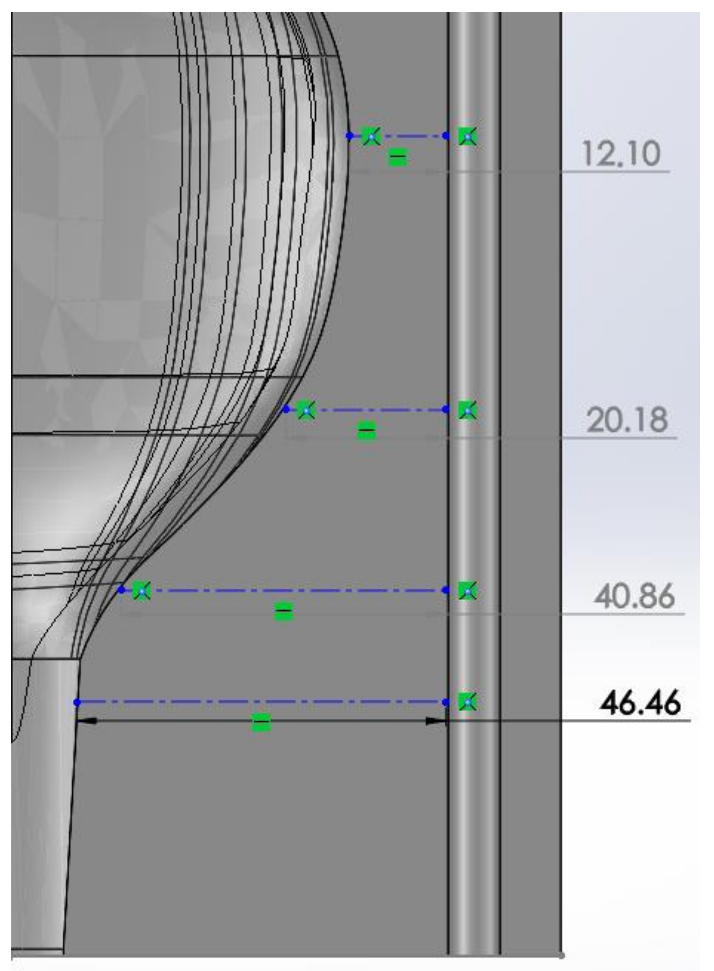
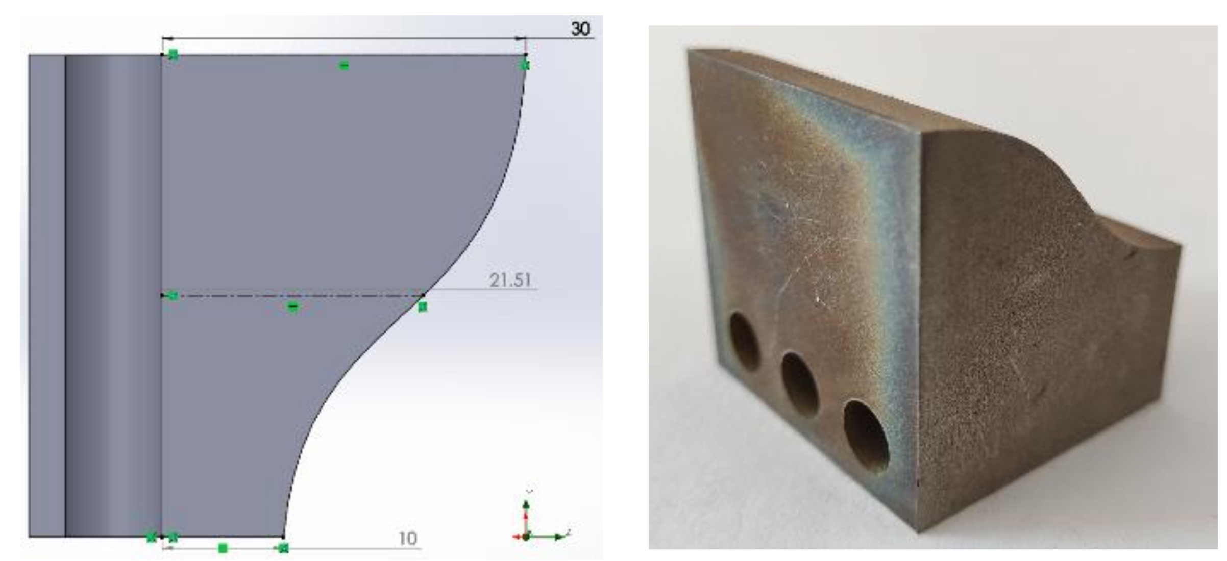
From a manufacturer’s point of view, Figure 1 shows a cut view of a complex bottle mold shape and the distance of the bore hole cooling channel from the molding surface. The mold manufacturer identifies 10 mm as the minimum distance from the bore to the mold surface for effective cooling instead of insulating. The test specimens were designed considering the required minimum distance specified by the manufacturer. The test specimen G#1—Vertiflow/control—in Figure 2 presents the 8 mm diameter bore from a minimum distance of 10 mm and a maximum of 30 mm from the representative molding surface. The bore diameter is the same as presented in glass molds and has a section area of approximately 50.3 mm2. This specimen is a representation of the traditional glass mold, and it is used for comparison to the conformal cooling geometries.
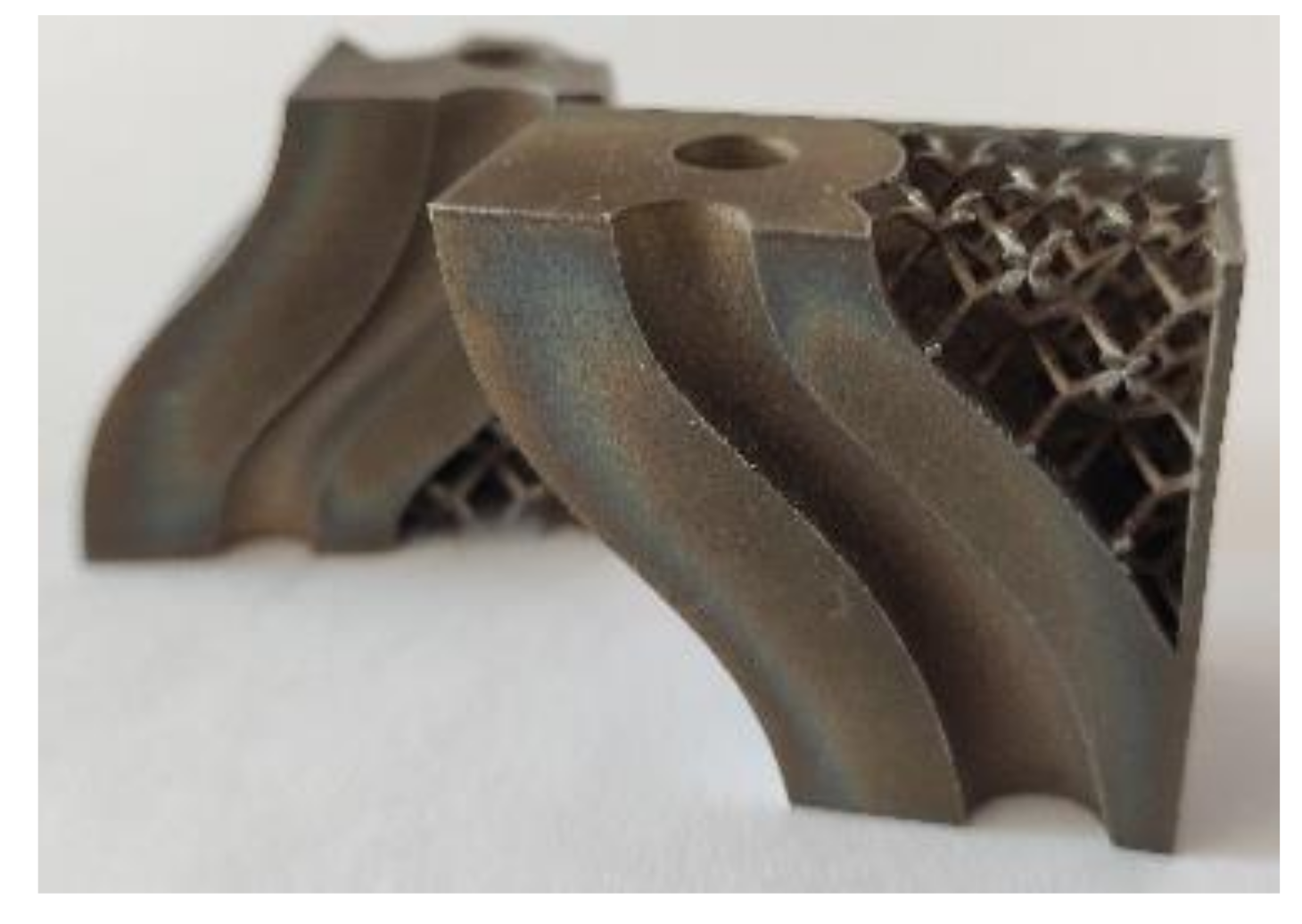
All test specimens were produced by additive manufacturing in a Trumpf TruPrint 1000 powder bed system to ensure the same material properties, the geometry being the only variation between them. The conformal specimens present the cooling channels at a constant distance of 10 mm from the representative molding surface. The remainder of the bulk was replaced by self-supporting truss geometries that ensure good mechanical properties, reduce the material necessary for its production and thus reduce the part weight and production time. The purpose of the conformal cooling channels is to remove heat from the curved surface; therefore, the remaining bulk material is mainly structural. Figure 3 presents the G#2—Circular conformal specimen, which includes the mentioned truss geometries in the structural volumes of the specimens.
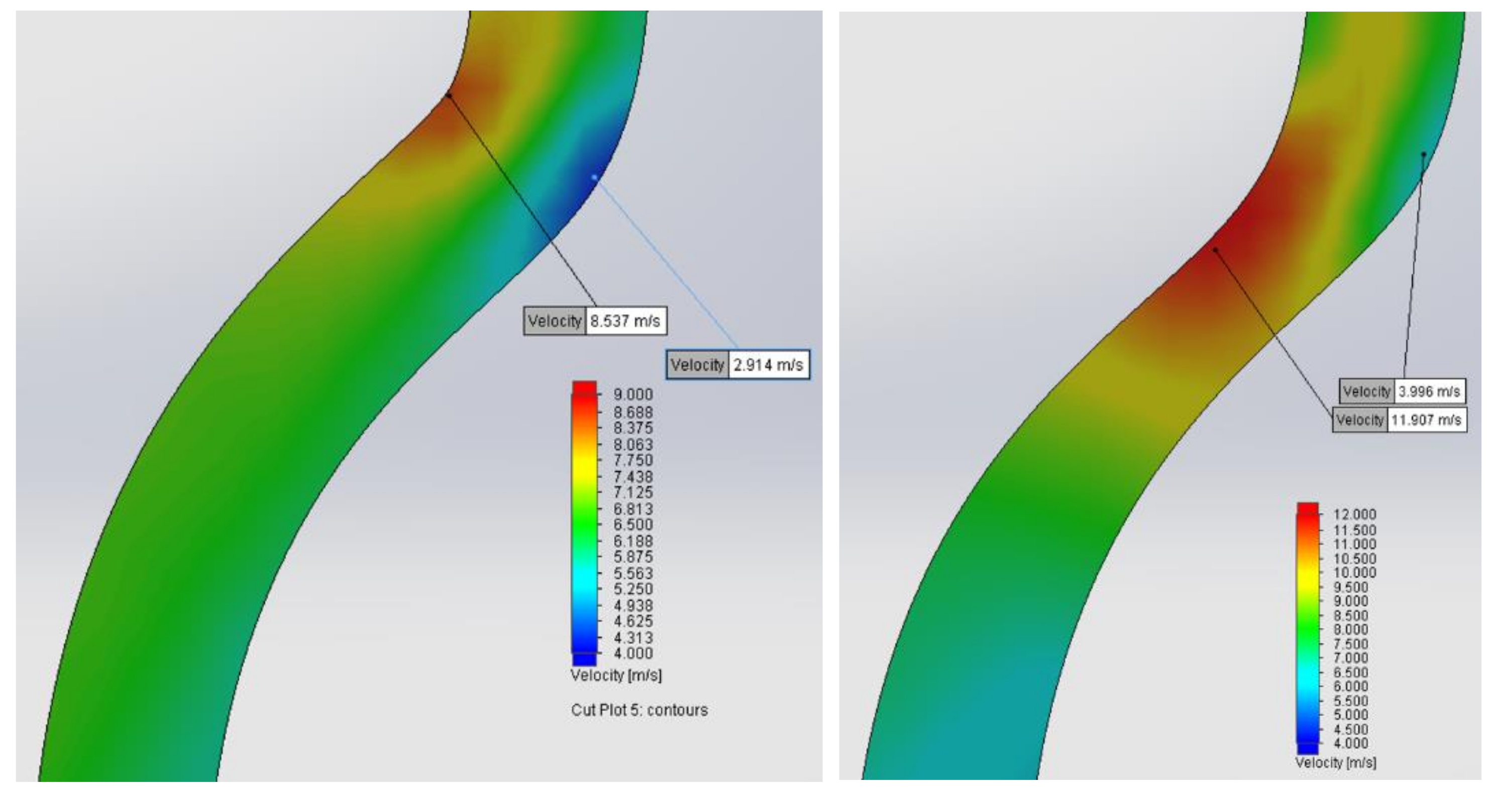
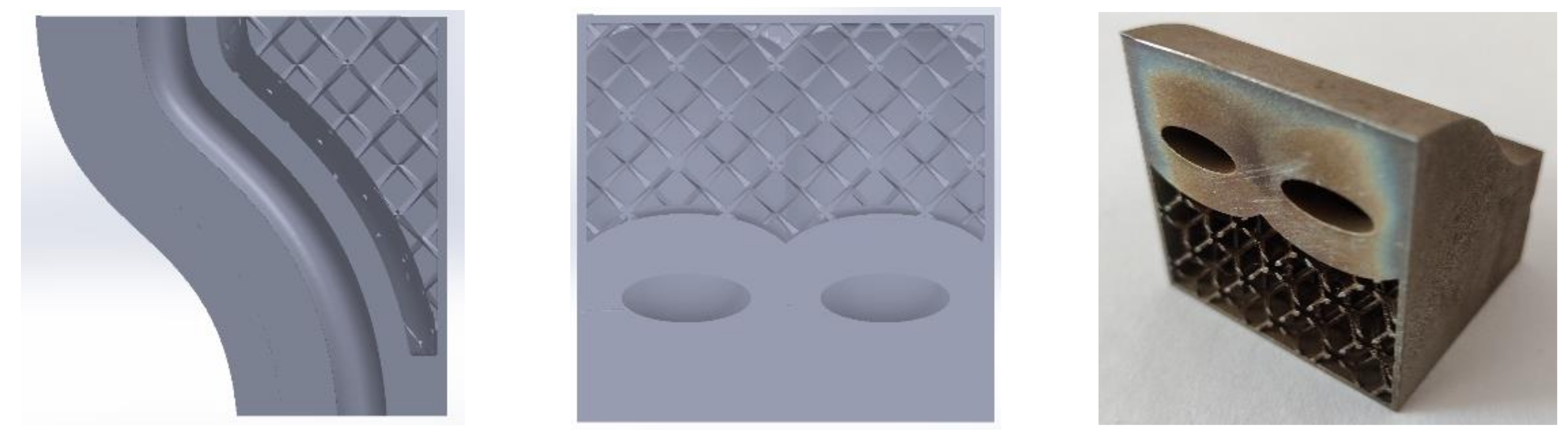
In relation to G#2, through CFD simulation, the formation of a vortex was observed, which is estimated to potentiate a non-uniform cooling due to airflow deceleration. A section area variation was designed to increase flow velocity and thus minimize the vortex formation. Figure 4 illustrates the simulations and allows us to conclude that there is an increase in air velocity for the cross-sectional area variation alternative, especially in the vortex formation region of the channel, as shown on the left of the mentioned figure. Figure 5 shows the mid-channel sectional cut of the G#2 specimen.
G#3—Elliptical conformal specimen, as shown in Figure 6, is expected to have a better performance than its circular counterpart due to a larger channel area near the representative molding surface. This channel geometry is also largely used in conformal cooling for plastic injection molding.
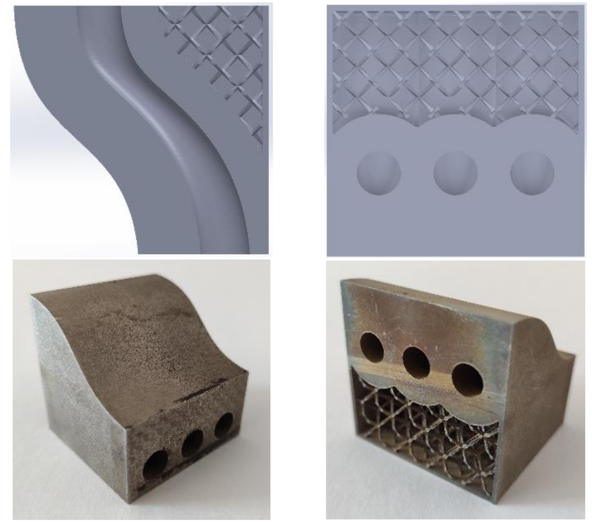
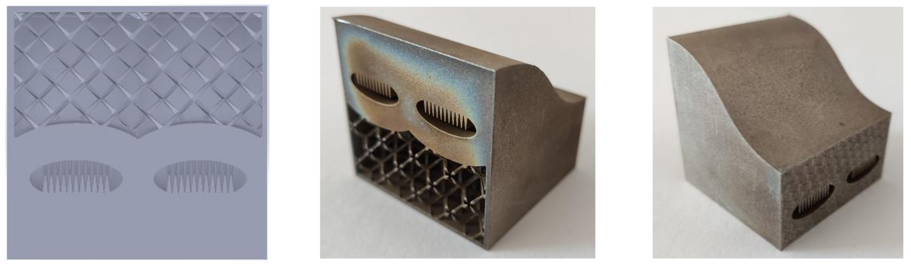
G#4—Elliptical conformal with fins presents the same channel geometry as G#3 but with the inclusion of a fin array to further increase the air contact area in the channel to increase cooling. Fin geometries are widely used in heat exchangers and other air-cooled components, and in this work, an attempt was made to incorporate these geometries inside the cooling channels, given that glass molds are also air cooled. The mentioned specimen is shown in Figure 7.
Experimental set-up.
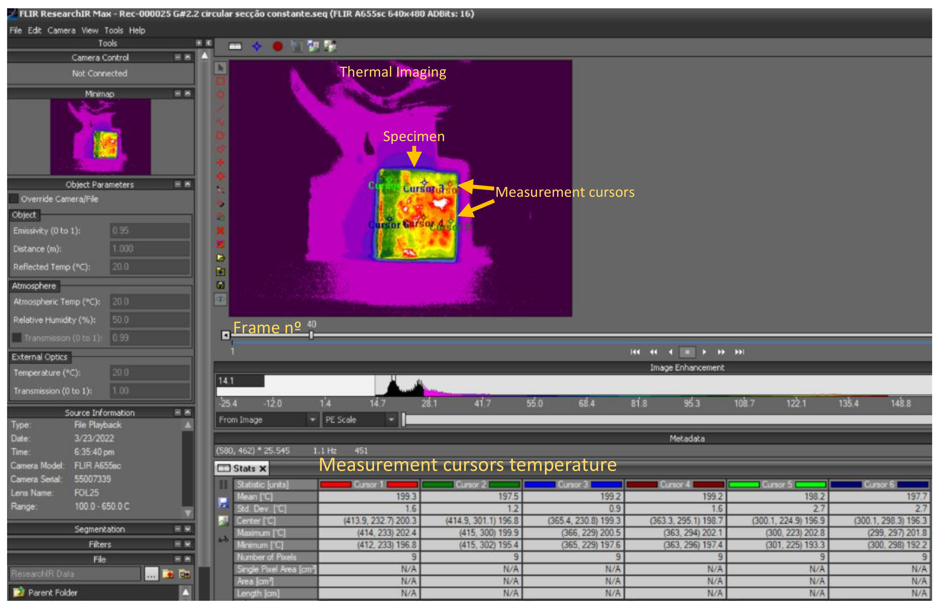
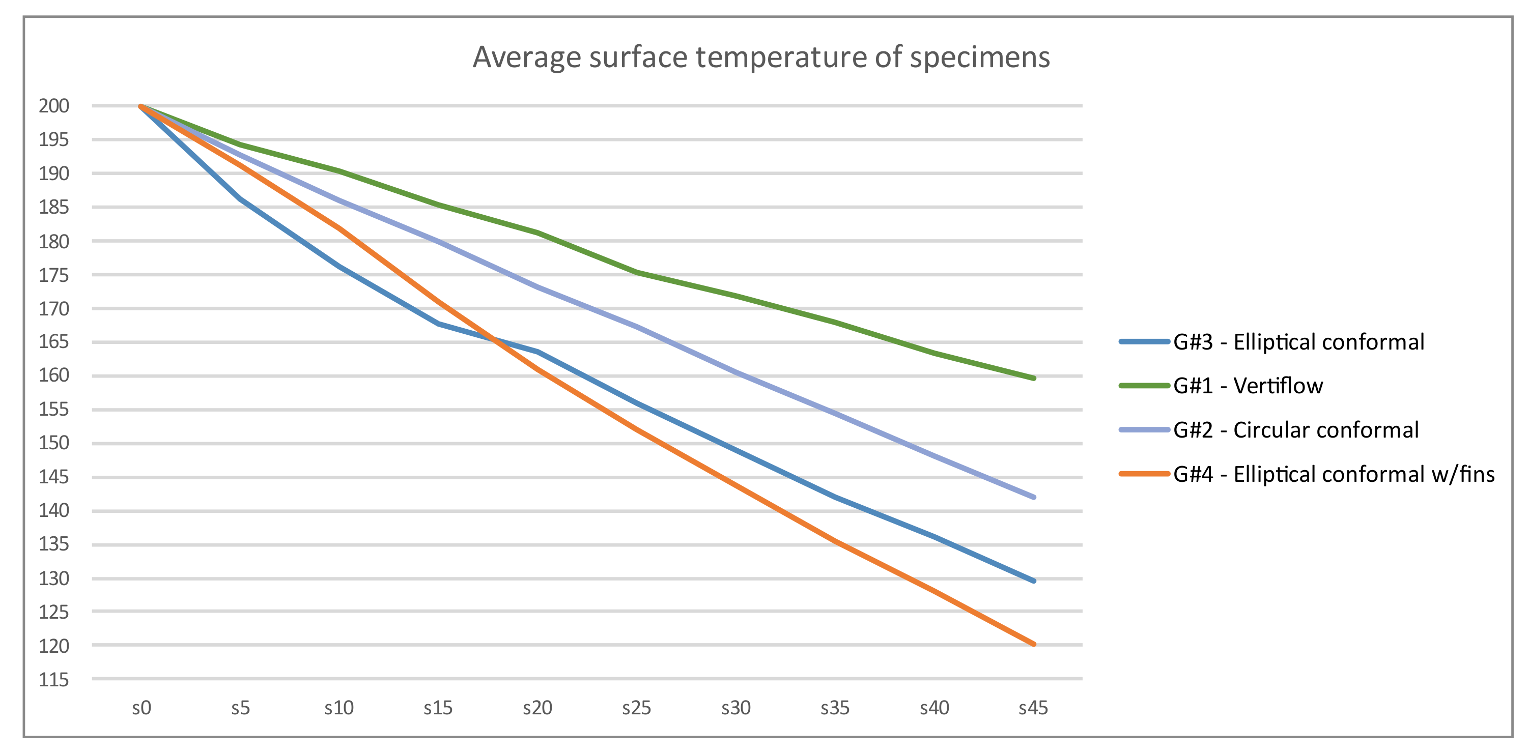
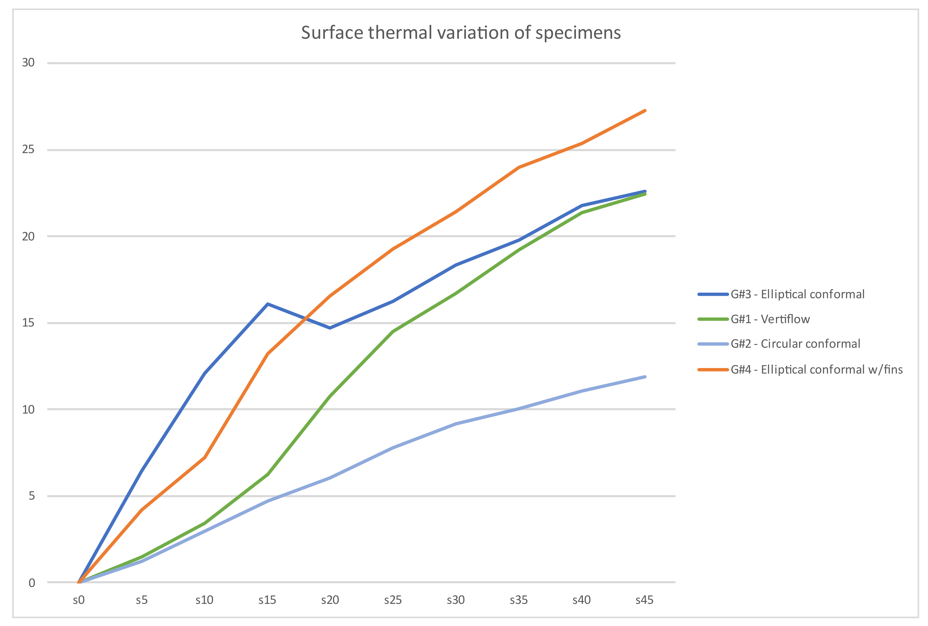
The experiment was designed to compare the cooling performance of the various test specimens. In order to register temperatures, a thermographic camera FLIR A655SC was placed on a tripod at a distance of 50 cm in video-record mode. The specimens were heated in an oven at 200 °C. The temperature was confirmed using an infrared thermometer. One by one, the specimens were replaced on top of a refractory ceramic plate in place, and the air was fed through the channels with a custom-designed adapter on a compressed air gun. The video was recorded using the native ResearchIR software from FLIR, as shown in Figure 8, at a rate of six frames per second. The temperature values were registered every 5 s on Excel, and the data were treated and presented in the form of a graph, as shown in Figure 9. The percentage of thermal variation for each specimen was also calculated, as it is an important factor in glass molds. To reduce defects on glass parts due to high temperature variation, the temperature profile uniformity is key to reducing tool wear from hotspots on the mold, or the increase in glass viscosity due to cold mould regions.
As expected, the results revealed the traditional mold representative specimen G#1—Vertiflow as one with the worst performance in reducing surface temperature. In these matters, the G#4—Elliptical conformal with fins had a higher surface heat reduction in all tested specimens, confirming that the addition of fins onto the cooling channels is an alternative with potential for further studies.
In terms of surface thermal variation, the best results were given by G#2—Circular conformal with a large margin, presenting only 11.86% of thermal variation, in comparison with the traditional G#1 of 22.46% and also presenting a much higher efficiency in reducing heat from the surface.
It is possible to conclude that conformal cooling channels have the potential to improve glass molding, not only in heat reduction, but also in controlling the thermal variation. More considerations and conclusions are presented in the full article. More experiments will be performed with higher temperatures to better establish a correlation of the presented test specimens with the glass molds.
Author Contributions
Conceptualization, P.S., J.F.; software, Solidworks, ResearchIR, validation, J.F.; writing—original draft preparation, P.S.; supervision, J.F. All authors have read and agreed to the published version of the manuscript.
Funding
This research received no external funding.
Institutional Review Board Statement
Not applicable.
Informed Consent Statement
Not applicable.
Data Availability Statement
Not applicable.
Conflicts of Interest
The authors declare no conflict of interest.
References
- Couceiro, J.M.; Frade, B.C. Conformação Automática de Formas Complexas em Vidro de Mesa; Universidade de Aveiro (Portugal) ProQuest Dissertations Publishing: Aveiro, Portugal, 2010; Available online: https://ria.ua.pt/bitstream/10773/2324/1/2010001280.pdf (accessed on 5 January 2022).
- Bewer, T. Blow Mould Cooling. Glass Worldw. 2007, 14, 30. [Google Scholar]
- Lankeu Ngankeu, P.S. Improvements to Emhart Glass Vertiflow Mold Cooling Applications in Glass Container Production. In 76th Conference on Glass Problems, Version A: A Collection of Papers Presented at the 76th Conference on Glass Problems, Greater Columbus Convention Center, Columbus, Ohio, November 2–5, 2015, Volume 37, Issue 1; Sundaram, S.K., Ed.; Ceramic Engineering and Science Proceedings; Wiley: New York, NY, USA, 2016; pp. 185–191. [Google Scholar] [CrossRef]
Figure 1.
Traditional Vertiflow channel and the distances from the molding surface. The distance between the moulding surface and the channel is presented by the measuring of the line segments shown.
Figure 1.
Traditional Vertiflow channel and the distances from the molding surface. The distance between the moulding surface and the channel is presented by the measuring of the line segments shown.

Figure 2.
CAD and manufactured G#1—Vertiflow/control specimen. The distance between the representative moulding surface and the channel is presented by the measuring of the line segments shown.
Figure 2.
CAD and manufactured G#1—Vertiflow/control specimen. The distance between the representative moulding surface and the channel is presented by the measuring of the line segments shown.

Figure 3.
CAD and manufactured G#2—Circular conformal specimen.

Figure 4.
CFD for airflow speed results on: (left) circular conformal of constant cross-section area, Vmax = 6.54 m/s, Vmin = 2.91 m/s; (right) circular conformal with cross-sectional area variation, Vmax = 11.90 m/s, Vmin = 3.99 m/s.
Figure 4.
CFD for airflow speed results on: (left) circular conformal of constant cross-section area, Vmax = 6.54 m/s, Vmin = 2.91 m/s; (right) circular conformal with cross-sectional area variation, Vmax = 11.90 m/s, Vmin = 3.99 m/s.

Figure 5.
Sectional cut of a G#2.

Figure 6.
CAD and manufactured G#3—Elliptical conformal specimen.

Figure 7.
CAD and manufactured G#4—Elliptical conformal with fins specimen.

Figure 8.
ResearchIR software interface.

Figure 9.
Results graphs: (above) Average surface temperature of specimens; (below) Surface thermal variation.
Figure 9.
Results graphs: (above) Average surface temperature of specimens; (below) Surface thermal variation.


Publisher’s Note: MDPI stays neutral with regard to jurisdictional claims in published maps and institutional affiliations. |
© 2022 by the authors. Licensee MDPI, Basel, Switzerland. This article is an open access article distributed under the terms and conditions of the Creative Commons Attribution (CC BY) license (https://creativecommons.org/licenses/by/4.0/).
Share and Cite
MDPI and ACS Style
Sereno, P.; Frade, J. Improvement of Mold Cooling for Automatic Glass Molding—A Preliminary Geometry Study on Representative Test Specimens. Mater. Proc. 2022, 8, 92. https://doi.org/10.3390/materproc2022008092
AMA Style
Sereno P, Frade J. Improvement of Mold Cooling for Automatic Glass Molding—A Preliminary Geometry Study on Representative Test Specimens. Materials Proceedings. 2022; 8(1):92. https://doi.org/10.3390/materproc2022008092
Chicago/Turabian StyleSereno, Pedro, and José Frade. 2022. "Improvement of Mold Cooling for Automatic Glass Molding—A Preliminary Geometry Study on Representative Test Specimens" Materials Proceedings 8, no. 1: 92. https://doi.org/10.3390/materproc2022008092