
A GEMMA-GRAFCET Generator for the Automation Software of Smart Manufacturing Systems
by
 , ,
, ,
Juan Manuel Castillo
1,2, 
Giacomo Barbieri
1,*,
Alejandro Mejia
1,
José Daniel Hernandez
1 and
Kelly Garces
2 1
Department of Mechanical Engineering, Universidad de los Andes, Bogotá 111711, Colombia
2
Department of Systems and Computing Engineering, Universidad de los Andes, Bogotá 111711, Colombia
*
Author to whom correspondence should be addressed.
Machines 2021, 9(10), 232; https://doi.org/10.3390/machines9100232
Submission received: 30 August 2021
/
Revised: 27 September 2021
/
Accepted: 28 September 2021
/
Published: 12 October 2021
(This article belongs to the Special Issue Intelligent Machines and Control Systems)
Abstract
:Within the Industry 4.0 revolution, manufacturing enterprises are transforming to intelligent enterprises constituted by Smart Manufacturing Systems (SMSs). A key capability of SMSs is the ability to connect and communicate with each other through Industrial Internet of Things technologies, and protocols with standard syntax and semantics. In this context, the GEMMA-GRAFCET Methodology (GG-Methodology) provides a standard approach and vocabulary for the management of the Operational Modes (OMs) of SMSs through the automation software, bringing a common understanding of the exchanged data. Considering the lack of tools to implement the methodology, this work introduces an online tool based on Model-Driven Engineering–GEMMA-GRAFCET Generator (GG-Generator)–to specify and generate PLCopen XML code compliant with the GG-Methodology. The proposed GG-Generator is applied to a case study and validated using Virtual Commissioning and Dynamic Software Testing. Due to the consistency obtained between the GG-Methodology and the generated PLC code, the GG-Generator is expected to support the adoption of the methodology, thus contributing to the interoperability of SMSs through the standardization of the automation software for the management of their OMs.
1. Introduction
Nowadays, manufacturing enterprises are facing fierce pressure to cope with the dynamic requirements of stakeholders and innovative business models [1], such as the mass-customization and personalization of the production [2]. In this context, a rampant process of digital transformation of production plants has taken place, referred to as Industry 4.0 [3]. Within this paradigm, manufacturing enterprises are transforming to intelligent enterprises constituted by Smart Manufacturing Systems.
Smart Manufacturing Systems (SMSs) are manufacturing systems that use real-time data to improve the accuracy of decision-making, enhance the efficiency and performance of the plant, and increase overall productivity [4]. To achieve these results, SMSs implement the paradigm of Cyber-Physical Systems (CPSs) [5]: engineered systems characterized with the communication between a physical asset (physical domain) and advanced processing capabilities (cyber domain) to exploit real-time data.
Like CPSs, SMSs exchange data [6]: (i) horizontally: to coordinate the heterogeneous systems that carry out the manufacturing process’s tasks; and (ii) vertically: to achieve advanced data processing capabilities through the communication in between the physical and the cyber domain—generally hosted in the enterprise cloud. Therefore, interoperability is fundamental to realize the SMS paradigm.
Interoperability is defined as the ability of systems to exchange data, and share information and knowledge [7]. Two components are necessary to achieve interoperability: (i) enabling technologies for the data exchange; and (ii) standard syntax and semantics to correctly interpret the information content of the data. Industrial Internet of Things (IIoT) provides the enabling technologies to implement the horizontal and vertical communication needed for the realization of SMSs [8]. However, interoperability still remains a challenge due to lack of universal standards [9].
In response to this issue, Barbieri and Gutierrez [10] proposed the GEMMA-GRAFCET Methodology (GG-Methodology): an approach and vocabulary for the management of the Operational Modes (OMs) of SMSs through the automation software, thus facilitating the exchange of information between the PLCs (Programmable Logic Controllers) and the external environment. The methodology consists of: (i) GEMMA-GRAFCET Representation (GG-Representation): to completely specify the management of the OMs with a standard syntax and semantics; (ii) Hierarchical Design Pattern (HDP): to generate hierarchical, modular, readable, and maintainable PLC code which consists of a one-to-one translation of the GG-Representation.
The presented GG-Methodology has been demonstrated to reach interoperability both within the horizontal and vertical integration. Concerning the horizontal integration, the methodology has been utilized for the implementation of a decentralized architecture of SMSs supervised from a central coordinator [11]. Concerning the vertical integration, it has been applied for the communication in between a PLC (physical domain) and a digital twin (cyber domain) [10]. However, in its current form the methodology must be implemented manually and is missing tools to enhance its usability.
In this work, Model-Driven Engineering (MDE) is intended as the use of models to specify the automation software of SMSs, and as the automatic transformation of the models into PLC code [12]. Due to the automatic generation of automation software, MDE presents the benefit to reduce both the time spent on writing the code and in the debug of errors introduced during the operation. Furthermore, MDE has been demonstrated to be particularly useful for [13]: (i) development of domain-specific models that facilitate communication with non-technical experts; (ii) simulation and testing; and (iii) consumption of models for analysis.
Given the benefits of MDE and the lack of tools to implement the GG-Methodology, this work introduces an online tool based on MDE—GEMMA-GRAFCET Generator (GG-Generator)— specify and generate PLC code compliant with the methodology. The tool is expected to support the adoption of the approach, thus contributing to the interoperability of SMSs through the standardization of the automation software for the management of their OMs.
Given the above, the article is structured as follows: Section 2 presents a state-of-the-art analysis of related work, and Section 3 summarizes the previously introduced GG-Methodology. The proposed GG-Generator is illustrated in Section 4. Section 5 applies the generator to a case study for its validation. Obtained results are discussed in Section 6 and finally, Section 7 presents the conclusions and sets the directions for future work.
2. Related Works
Automation software is exponentially growing in modern SMSs. Consequently, the time necessary to develop, debug, and maintain the software is increasing. One way to manage this complexity is to develop software using appropriate methods of abstraction [14]. Model-Driven Engineering is an abstraction method that can concern various model-driven approaches to software development, including model-driven architecture, domain-specific modeling, and model-integrated computing. Surveys demonstrating benefits and challenges of MDE can be found in different works [15,16].
In industrial automation, MDE has been adopted for the generation of different software artifacts. For instance, Wehrmeister et al. [17] combined UML and aspect-oriented software development to design real-time and embedded automation systems. In Vyatkin et al. [18], Matlab/Simulink models were utilized to support the generation of executable IEC 61499 code for distributed systems.
In the context of IEC 61131-3 code, different literature reviews have dealt with MDE approaches [12,19,20]. Furthermore, a framework was proposed to compare the different methodologies for the generation of IEC 61131-3 code to support researchers and practitioners in selecting approaches tailored to the considered case study, and in identifying research opportunities [21]. The methodologies have been classified into: (i) rule-based generation based on plant structure [22,23]; (ii) higher-level programming [24,25,26]; and (iii) higher-level programming using plant structure [27,28,29].
MDE through higher-level programming requires control practitioners to formalize requirements and design in a higher-level modeling language (e.g., UML, SysML, GRAFCET, etc.), and to establish a mapping between the elements of the higher-level language and IEC 61131-3 constructs. The main drawback of this approach is that most of the proposed methodologies are based on modelling languages which are usually not familiar to the designated users [30]. In response to this, Julius et al. [31] proposed the use GRAFCET to model automation software, since it is widely accepted within the automation community [32]. Then, they introduced a systematic approach to automatically translate GRAFCET diagrams into PLC code.
Even if GRAFCET is accepted within the automation community, it does not provide a general approach for the definition and handling of the OMs of SMSs [33]. Therefore, researchers started looking at guidelines introduced from industrial and academic associations. GEMMA is a checklist which allows to graphically define all the start and stop modes of a system and their evolution [34]. S88 standard is used specifically to guide the development of batch control processes [35]. PackML is specialized for the OMs of packaging machinery [36].
Concerning the conversion of GEMMA-based specifications into automation software, Alvarez et al. [37] developed the ‘Methodology for industrial Automation systems’ (MeiA) supported with an implementation framework. This methodology combines GEMMA, UML use case diagrams and GRAFCET to assist the control practitioners during the analysis, design, and coding phases. OMs are identified by means of the GEMMA guideline. Use case diagrams are utilized to define the actors that take part in the OMs. A set of GRAFCET templates assists in the design of the OMs specified in accordance with the GEMMA guideline. Finally, MDE is adopted to convert GRAFCET diagrams into Sequential Function Chart (SFC) programs.
Due to some limitations detected in the MeiA approach such as the lack of formalism and the readability of the generated code, Barbieri and Gutierrez [10] developed the GEMMA-GRAFCET Methodology for the PLC management of the OMs of SMSs using the GEMMA guideline, and demonstrated its fulfillment of some of the interoperability needs of modern SMSs. Due to lack of tools for its implementation, the novelty presented in this work is the introduction of an online tool for the GG-Methodology.
3. GEMMA-GRAFCET Methodology
In this section, the GG-Methodology proposed in [10] is resumed since this work constitutes its extension. Section 3.1 illustrates the GG-Representation for the specification of the OMs of SMSs, while Section 3.2 describes the HDP for the generation of PLC code from specifications expressed in accordance with the defined GG-Representation. Finally, Section 3.3 shows an application example for the sake of clarity. It must be clarified that most of the content that describes the GG-Representation and the HDP is retrieved from [11].
3.1. GEMMA-GRAFCET Representation
GEMMA (Guide d’Etude des Modes de Marche et d’Arrt) is a checklist which allows to graphically define all the start and stop modes of a system and their evolution [34]. However, GEMMA is partially specified with respect to the syntax and semantics causing misunderstandings and possible emergent behaviors. To semantically specify the GEMMA guideline, GRAFCET international standard (IEC 60848 [38]) has been adopted [10].
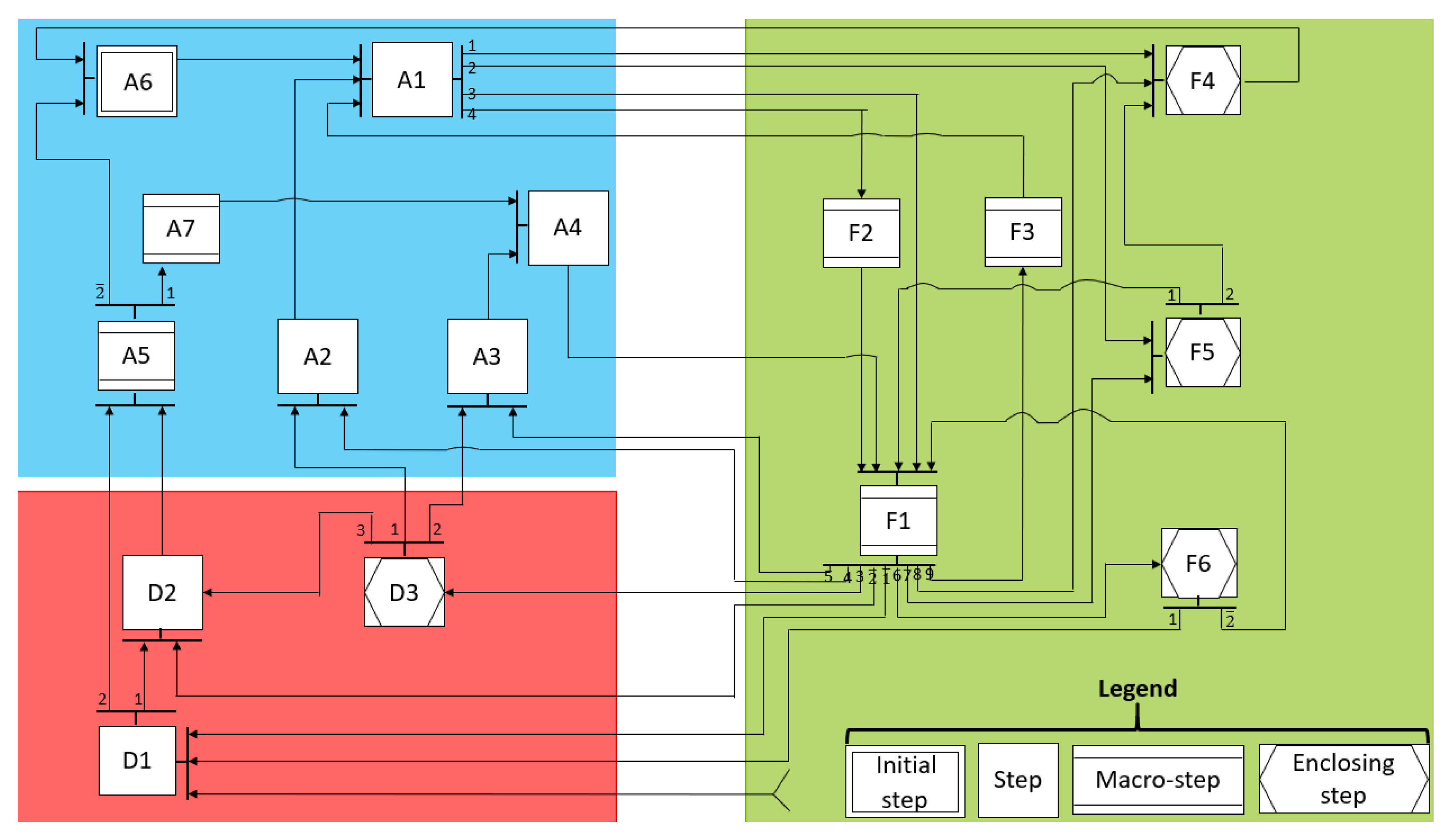
The GRAFCET model of the GEMMA guideline is shown in Figure 1. States are grouped into three families of start and stop modes: ‘F family’ for the operation procedures, ‘A family’ related to the stop procedures, and ‘D family’ concerning the failure procedures. A step defines a state that does not contain a nested behavior. The use of a macro-step indicates that its outgoing transitions can only fire when the exit step of the nested behavior is active. Whereas, the outgoing transitions of an enclosing step can fire independently from the active step of the nested behavior. The initial step indicates from which state the system starts to operate once initialized. Reset transitions are used since in GRAFCET the nested behavior must be initialized each time the super-ordinate state is entered. When a state has more than one outgoing transition, a number is placed on each transition to indicate its priority; i.e., the order in which conditions are evaluated within the code. Finally, a negation operator can be placed on the priority number to change the behavior of the composite state with respect to the one illustrated in the representation; i.e., from macro-step to enclosing step and vice-versa. Due to the implementation of the GEMMA guideline with the GRAFCET modeling language, this representation can be used to specify the OMs of SMSs without the development of emergent behaviors [10].
3.2. Hierarchical Design Pattern
Function Blocks (FBs) are adopted to hierarchically structure the code. One program is generated for implementing the behavior of the GEMMA layer (Figure 1) and one FB for each ‘GEMMA state’ that contains a nested behavior; i.e., macro-steps and enclosing steps. Only the GEMMA program is scheduled through a periodic task, while the execution of the nested behavior is invoked from the ‘GEMMA active state’ by calling the corresponding FB.
The GEMMA layer is converted into Structured Text (ST) PLC code following the pattern illustrated in [39]. Since the philosophy of the GEMMA guideline is to have only one state active at a time, a scalar State variable is used as a discriminator of a switch statement; i.e., CASE .. OF in ST. Transitions are evaluated—in accordance with their priority and negation operators—by means of IF .. THEN constructs and if a transition is fireable, the new state is assigned. To implement the proposed scheduling strategy, each ‘GEMMA state’ invokes the FB that contains its nested functionality. Finally, entry actions are executed by using an Entry flag and an IF .. THEN construct that resets the flag once the entry action has been performed.
To manage reset transitions and macro/enclosing steps, two ‘flags’ are introduced: Initialization and Complete, respectively declared as input and output variables of each FB. Initialization is utilized for implementing the reset transition behavior. Initialization is set on the entry action of each ‘GEMMA state’ and reset on the do action. Whereas, the Complete flag is used to implement the macro-step behavior. The outgoing transitions of a macro-step have an additional AND condition consisting in the Complete flag. This flag is set within the exit step of the nested behavior and reset during its reset transition. Whereas, an enclosing step does not have the Complete flag condition on the outgoing transitions.
Finally, in this work an additional functionality is integrated with the pattern presented in [10]. An optional token functionality is implemented for the variables within the condition of the outgoing transition of a macro-step. Since the transition of a macro-step can fire only when the Complete flag is active, the information content of variables utilized within the condition may be lost if it is not saved. For instance, if the user temporally presses a push button and the nested behavior has not been completed, the information would be lost. Therefore, a token can be set once the variable associated to the token changes its state, and reset after the firing of the transition.
3.3. Application Example
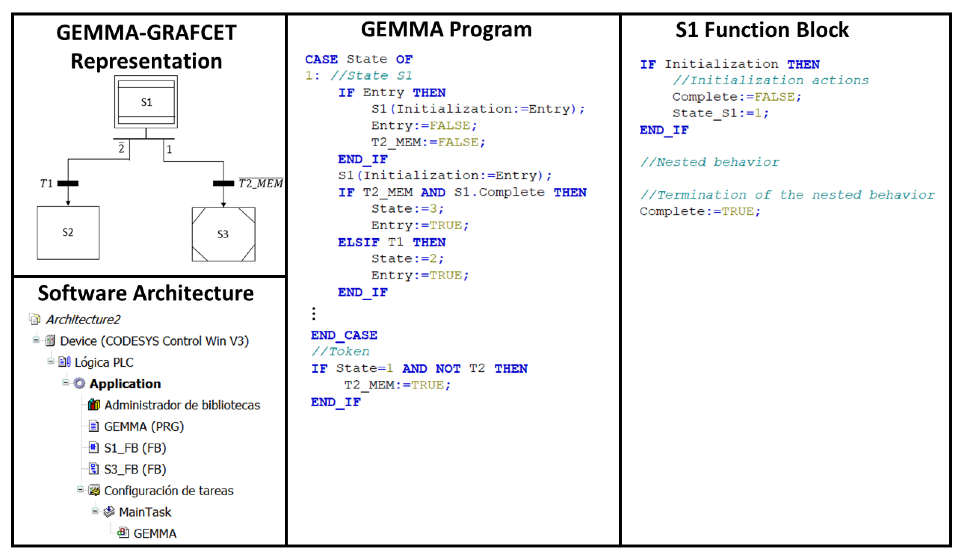
The specifications of the application example are shown in the first column of Figure 2. These mimic a GEMMA diagram that includes initial macro-step S1, step S2, and enclosing step S3. An ‘or divergence’ is implemented as the outgoing transition of the initial step S1, in which has higher priority than T1. Furthermore, transition T1 has a negation operator on its priority indicating that S1 must be considered as an enclosing step–when T1 is evaluated.
The software architecture is depicted in the second column of Figure 2. It can be noticed that a program is created for the GEMMA diagram, while FBs for the states that have a nested behavior; i.e., S1 and S3. GEMMA is the only scheduled program, while S1_FB and S3_FB are invoked from the GEMMA program.
The third column of Figure 2 illustrates the code written within the GEMMA program for the initial macro-step S1. The Initialization flag of its FB is set as entry action. Then, the FB that implements its nested functionality (i.e., F1_FB) is invoked as continuous action. After that, outgoing transitions are evaluated. is evaluated before T1 since it has higher priority. Furthermore, T1 transition makes the macro-step S1 behave as an enclosing step, since it has a negation operator; see the first column of Figure 2. Therefore, the Complete flag is not evaluated in the transition towards S1. It can be noticed that a token is utilized for to not lose the information content of when the nested behavior has not been completed yet.
Finally, the code within S1_FB is shown in the fourth column of Figure 2. The Initialization flag is utilized for initializing the behavior as soon as the state is entered, and its actions include the reset of the Complete flag and the State_S1 variable. Then, the nested behavior is performed, and the Complete flag is set once the nested behavior has been completed.
4. GEMMA-GRAFCET Generator
In this section, the GG-Generator is illustrated. Section 4.1 and Section 4.2 respectively summarize the requirements and the design decisions that guided the development of the GG-Generator, while Section 4.3 shows its implementation.
4.1. Requirements
The GG-Generator has the objective to ease and automate the implementation of the GG-Methodology. Therefore, the following requirements must be fulfilled:
- GEMMA-GRAFCET Representation: an online Graphical User Interface (GUI) must be developed for the definition of the automation software specifications. A ‘default’ template model containing the ‘GEMMA families’, and all the ‘GEMMA states’ and transitions must be available. Then, users must instantiate the template model by changing the typology of the states (initial step/step/macro-step/enclosing step), and hiding the states and transitions that are not necessary for the case study. Furthermore, they need to declare the different variables that will be utilized to define the conditions of the transitions, along with their data type and optional default value. Finally, they must be able to specify the conditions, tokens, priorities, and negation operators of the transitions;
- Hierarchical Design Pattern: once the automation software has been specified through the GG-Representation, users must be able to trigger the transformation of the instantiated model into PLC code. Then, the generator must implement the HDP following the rules illustrated in Section 3.2;
- Generator Output: PLCopen XML code (https://plcopen.org/technical-activities/xml-exchange accessed on 1 October 2021) must be generated to be compatible with the different PLC vendors available in the market. Furthermore, a serialized model representation must be provided to save, import, and export the model of the automation software specifications;
- Input validation: different analysis must be performed to detect errors that may be implemented by the users during the specification of the automation software. These must include the search of: (i) syntax errors such as typos in the definition of the data type of a variable; (ii) semantics errors such as the utilization of an undeclared variable within the condition of a transition. Nevertheless, in case of user approval, PLC code must be generated also in presence of errors, since the control practitioner may prefer to fix errors on the PLC code than the GG-Generator.
4.2. Design
Models are the central concept of the MDE approach and must conform with metamodels; i.e., must satisfy the rules defined at the level of their metamodel. In this context, a metamodel is intended as a specification model that defines the structure of the modeling language utilized for the modeling activity [40]. In a typical MDE process [41], models are created by users and converted into software artifacts—typically source code, XML and other text files—through Model-to-Text (M2T) and/or Model-to-Model (M2M) transformations. For practical purposes, in the GG-Generator a template (initial) model is provided to the users containing all the default elements of the GG-Representation. Then, the GUI allows users to customize such a template model by selecting the elements necessary for the particular automation software of the considered SMS.
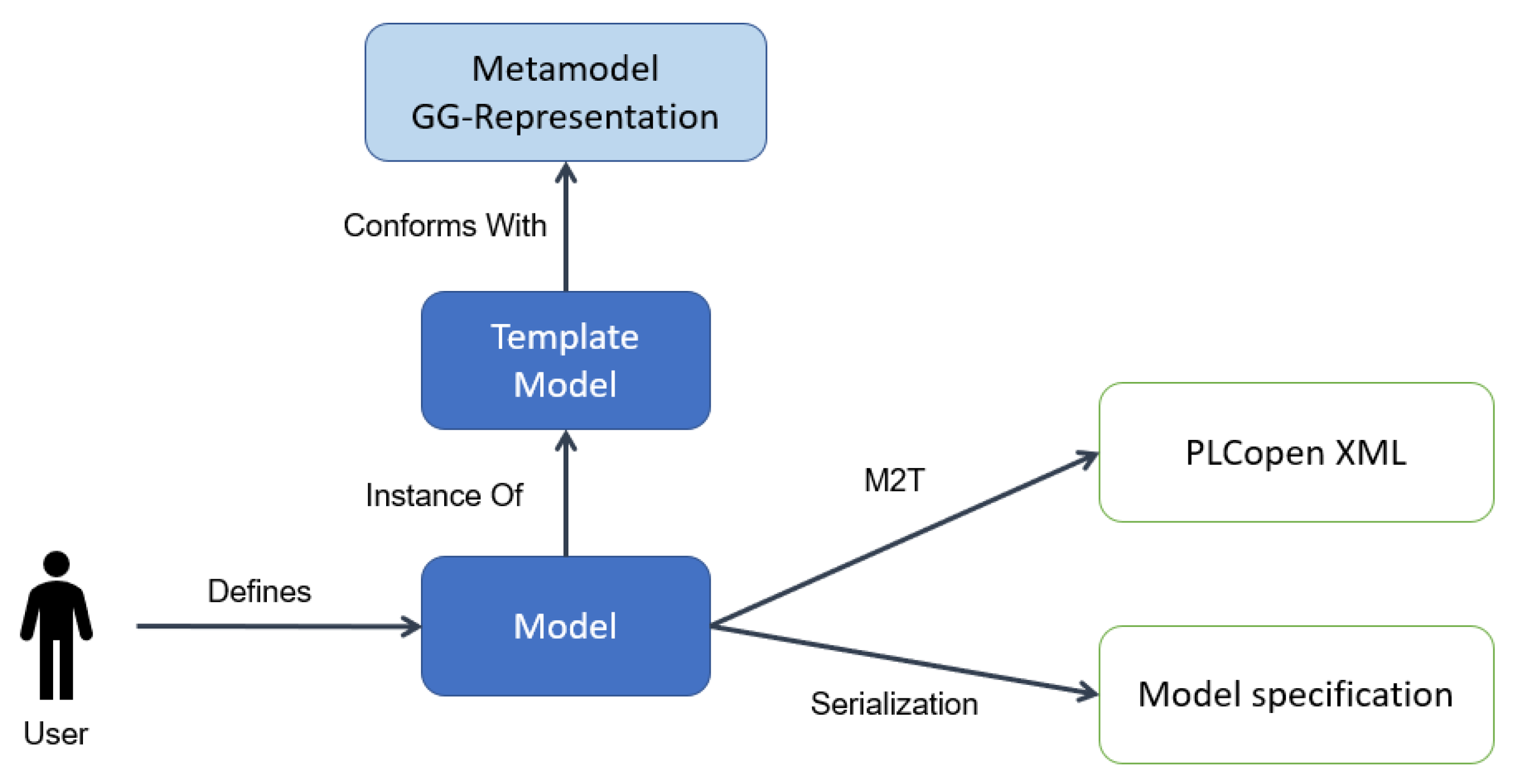
Given the above, the MDE transformation chain designed for the GG-Generator is depicted in Figure 3. The metamodel abstracts the concepts of the GG-Representation illustrated in Section 3.1. The template model of the GG-Representation is built compliant with the metamodel and contains the ‘GEMMA families’, and all the possible ‘GEMMA states’ and transitions. A GUI enables the instantiation of the particular automation software through the modification of the template model. Thus, through the GUI, users can change the typology of the states, hide states, and transitions, declare variables, and specify conditions, tokens, priorities, and negation operators of the transitions. Different analysis are performed to detect and notify errors during the user instantiation of the template model. Finally, an M2T and serialization are adopted to generate the different software artifacts. In particular, M2T implements the HDP defined in Section 3.2 and is utilized to generate PLCopen XML code. Whereas, serialization enables the saving, import, and export of the model.
4.3. Implementation
Next, the implementation of the GG-Generator is illustrated. Section 4.3.1 presents the defined metamodel, and Section 4.3.2 the template model and the online GUI to instantiate it into a model. Section 4.3.3 describes the M2T and serialization transformations for generating the software artifacts. Finally, Section 4.3.4 shows the analysis performed to detect and notify errors during the user specification of the model, and Section 4.3.5 the software technologies selected for the implementation of the GG-Generator.
4.3.1. Metamodel
The metamodel used to specify the GG-Representation is depicted in Figure 4 through a UML (http://www.uml.org/ accessed on 1 October 2021) class diagram. It consists of:
- GEMMA-GRAFCET: the main actor of the metamodel that contains steps and variables. Furthermore, it constrains the states within the ‘F family’ to act as enclosing steps. In this way, these states can move the system towards the ‘Emergency stop’ state (i.e., D1), independently from the active step of the nested behavior [10];
- Step: belongs to a ‘GEMMA family’ (i.e., failure, operation, or stop family) and can be either simple, enclosing, or macro-step. Only one step can be selected as the initial one;
- Transition: directed line that connects a source step to a target one. A priority—integer number—is specified when the source step has more than one outgoing transition. A transition has an associated condition that indicates when the transition to the target state can take place. A ‘negate’ option can be selected for enclosing and macro-steps to change the behavior of the source step with respect to the one illustrated in the representation—when the negated transition is evaluated;
- Variable: either a physical input or a software variable utilized to define the conditions of the transitions. It is characterized by a data type, a size, and an optional default value. A memory can be set to generate a token of the associated variable. The token can either be normally open or normally closed. In the first case the token is generated when the associated variable turns TRUE, while in the latter when the associated variable turns FALSE.
4.3.2. Model and GUI
The GG-Generator is illustrated in Figure 5. Its source code is made available to the reader (https://github.com/GiacomoBarbieri1/MDE_GEMMA-GRAFCET accessed on 1 October 2021), along with the web application (GUI) (https://giacomobarbieri1.github.io/MDE_GEMMA-GRAFCET/ accessed on 1 October 2021) and a tutorial for its utilization (https://youtu.be/auUBkrvyfos accessed on 1 October 2021). The web application is standalone and does not require a backend server since all the functionalities are implemented on the client side. The web application consists of the following elements:
- Toolbar: upper bar (see Figure 5) through which the user can generate a PLC code, and save, import, and export the model. The RESET button enables to restore the model to the state of the template model. Finally, the HIDE DELETED button is used to hide the steps and transitions not necessary for the case study, since by default these are displayed in opaque color;
- Model: canvas in which the model is represented. The first time the web application is opened and after the reset of the model, the template model is available to the user. The template model contains all the ‘GEMMA states’ and transitions. Steps appear with arbitrary typologies, while transitions with arbitrary priorities and without conditions. The user can select steps and transitions, and personalizes them through the options available in the other regions. It must be noticed that the steps and transitions are fixed in the canvas. Since the GG-Representation implements the GEMMA guideline, it was not necessary to provide to the user the possibility to add further states and transitions, and to modify their spatial positions;
- PLC Code: region that illustrates a preview of the GEMMA program that would be generated with the actual state of the model;
- Step: region through which the user can hide steps, change their typology, and select the initial one;
- Transition: region through which the user can hide transitions, specify their priorities and conditions, and select negated transitions. In the case of macro-steps, the Boolean variables of the conditions can be defined as tokens;
- Variables: region through which the user creates the variables utilized to define the conditions of the transitions. Data type and size must be specified for each variable, while the default value is left as optional.
4.3.3. Model Transformation
As depicted in Figure 3, the GG-Generator implements a model transformation and a serialization. On the one hand, the Model-to-Text transformation is developed to convert the model into PLCopen XML code. Following the HDP, variables are declared as global variables, a ST GEMMA program implements the behavior of the GEMMA layer, and FBs are created for each ‘GEMMA state’ that contains a nested behavior. On the other hand, the serialization enables to save the state of the model through a JSON file. The obtained file can be imported and exported respectively to and from the web application, and can restore the model state after the closing of the web browser.
4.3.4. Input Validation
A different analysis is performed to detect and notify errors during the user specification of the automation software. In its current version, the GG-Generator can detect:
- Initial step: due to the missing of the initial step specification;
- Deadlock: step without output transitions;
- Unreachable state: step without input transitions;
- Boolean expression: due to the use of invalid operators and/or variables in the condition of the transition;
- Variable name: due to the use of duplicate or empty names;
- Default value: due to the specification of a default value that is not compliant with the variable data type.
Once an error is detected, a warning is displayed close to the fault input field. Finally, a list of all the errors is displayed before the generation of the PLC code. Nevertheless, in case of user approval a PLC code is generated also in presence of errors.
4.3.5. Software Technologies
Next, the software technologies selected for the implementation of the GG-Generator are listed:
- Web Technologies (HTML, CSS): chosen for the implementation of the GUI due to their popularity, extensibility, flexibility, and ease of distribution;
- TypeScript (https://www.typescriptlang.org/ accessed on 1 October 2021): main programming language utilized for the functionalities of the GG-Generator. TypeScript is selected for its maturity, popularity, and similarity with JavaScript: the final transpilation target of most web applications. With respect to JavaScript, TypeScript provides compile-time static typing which improves maintainability and reduces common typing errors;
- ReactJS (https://github.com/facebook/react/ accessed on 1 October 2021): framework for creating web applications. One of the first to propose declarative mapping from the application state to the GUI. It is selected due to its popularity and the TypeScript support;
- MobX (https://mobx.js.org/ accessed on 1 October 2021): used as a dependency library needed for the implementation of the web application. It provides tools for incremental computation and for the reaction to changes observed in the application state;
- Material Design (https://material-ui.com/ accessed on 1 October 2021): main tool adopted for the styling of the GUI;
- Antlr (https://www.antlr.org/ accessed on 1 October 2021): tokenizer and parser generator for language grammars. This tool is adopted for the parsing of the Boolean expressions specified within the conditions of the transitions. In particular, the Antlr open-source TypeScript library (https://github.com/tunnelvisionlabs/antlr4ts/ accessed on 1 October 2021) is utilized as dependency.
5. Case Study
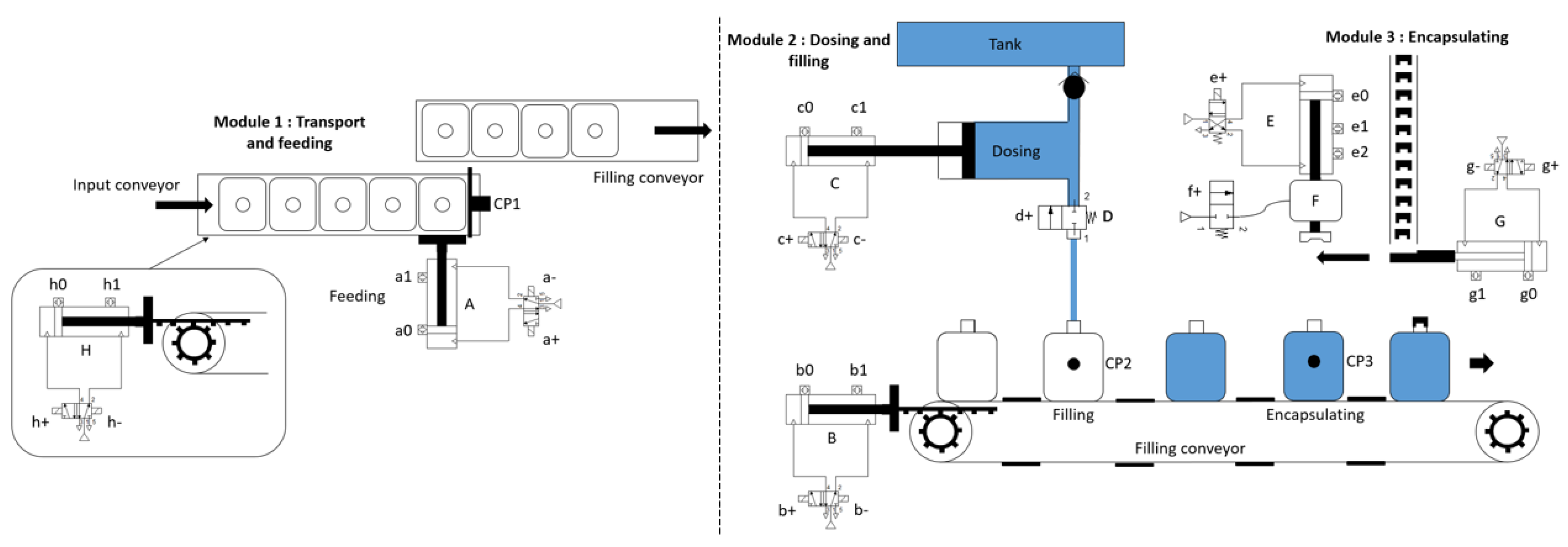
A case study was developed to test the GG-Generator. An automatic machine for filling and encapsulating bottles consists of three stations (Figure 6): (i) transport and feeding; (ii) dosing and filling; and (iii) encapsulating. Two stepping slat conveyors allow the simultaneous operation of the three stations. Extension of pneumatic cylinders H and B, respectively, determines the incremental advance of the input and filling conveyors. The transport and feeding station is constituted by pneumatic cylinder A that is responsible for the feeding of the bottles from the input to the filling conveyor. The dosing and filling station is composed by a volumetric dispenser actuated from pneumatic cylinder C, and by an on/off valve (D) used to open and close the liquid supply. The encapsulating station has a pneumatic cylinder (G) to feed the cap that is recollected and released on the bottle through the movement of cylinder E. Vacuum pump F is utilized to grab and hold the cap. Finally, magnetic limit switches are used to signal the position of the pneumatic cylinders and light barrier sensors to indicate the presence of a bottle on each station.
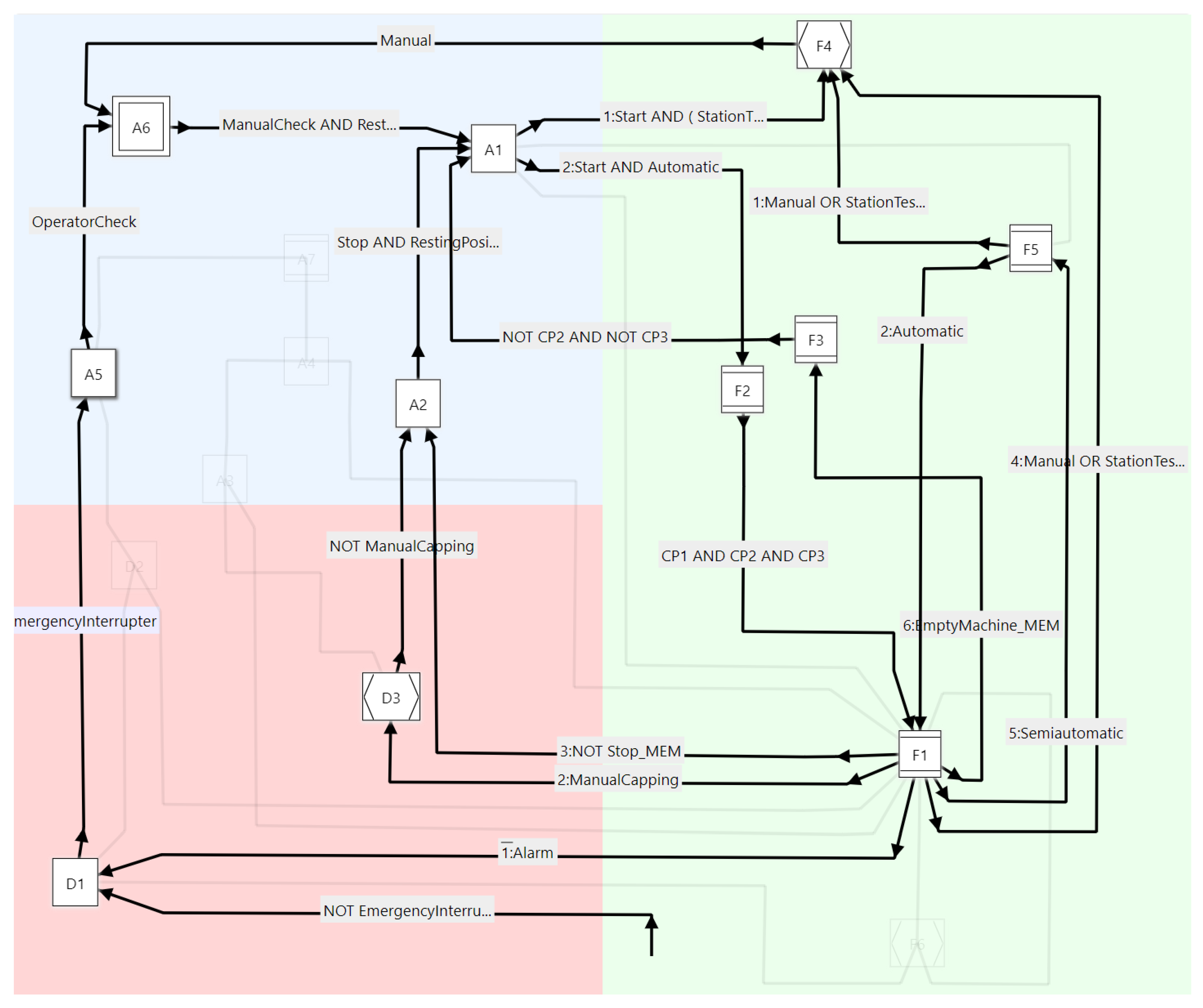
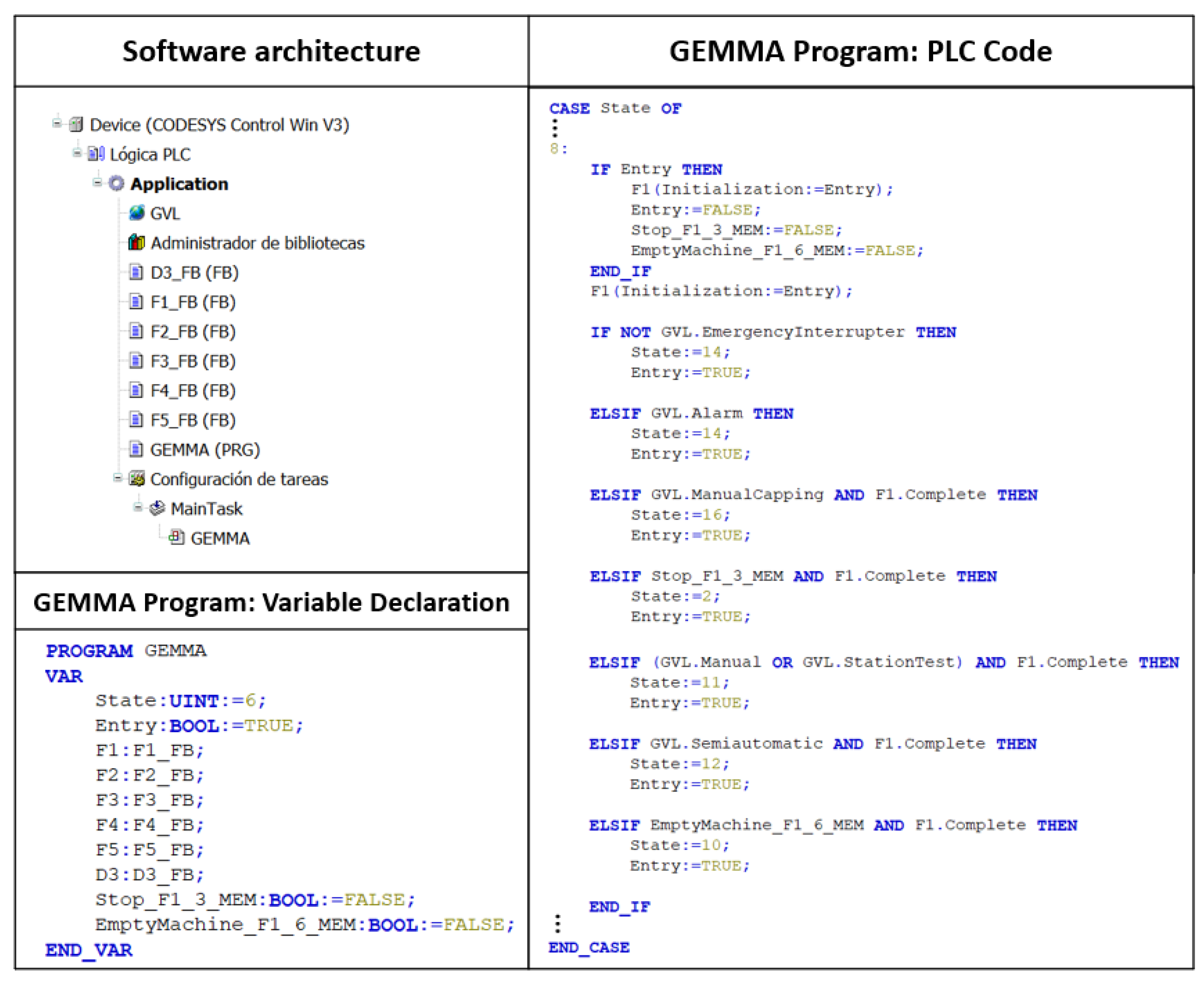
First, the template model was instantiated for the specification of the automation software of the filling and encapsulating machine through the GG-Representation (Figure 7). After the identification of the GEMMA hierarchical layer, the nested behavior of each state was defined. The nested behavior is made available to the reader (https://github.com/GiacomoBarbieri1/MDE_GEMMA-GRAFCET/blob/master/SoftwareSpecifications_CaseStudy.pdf accessed on 1 October 2021) but it is not illustrated since it does not constitute the focus of this work. Then, PLCopen XML code was automatically generated and imported into the CoDeSys (https://www.codesys.com/ accessed on 1 October 2021) programming environment; see Figure 8.
In accordance with the HDP, the software architecture of the obtained PLC code contains one program—GEMMA—to implement the behavior of the GG-Representation, and one FB for each macro-step and enclosing step. All the variables created in the GG-Representation are declared as global variables. Whereas, the program local variables consist of: (i) FBs’ instances; (ii) State variable; (iii) Entry flag; (iv) tokens. The GEMMA program is scheduled with a periodic task, while the FBs are invoked from the GEMMA program as shown on the right hand-side of Figure 8 for the F1 state.
6. Results and Discussions
A kinematic model of the filling and encapsulating machine was built in Experior (https://xcelgo.com/ accessed on 1 October 2021) (Figure 9) and connected to CoDeSys for the implementation of Virtual Commissioning (VC) [42]. CoDeSys offers an integrated Soft-PLC—named CoDeSys Win Control V3—that emulates an industrial controller under Windows, enabling the virtual execution of the automation software. Therefore, VC was performed by interfacing Experior and CoDeSys Win Control V3 using the OPC protocol (Open Platform Communications). CoDeSys Win Control V3 was run providing the control functionality to the Experior model of the physical plant. A video illustrating the result of the VC is made available to the reader (https://www.youtube.com/watch?v=9v48dQM44RA&list=PLXnpmcz3YbS-YpaXKUeQKXyK4PorRlDzx accessed on 1 October 2021).
Then, test cases were generated to verify the consistency between the specifications of the automation software and the obtained PLC code. The specifications were converted into test cases and Dynamic Software Testing was utilized to evaluate their fulfilment [43]. In Dynamic Software Testing, the different actions that constitute a test case are verified by evaluating the values acquired by selected software variables. CoDeSys Test Manager (https://store.codesys.com/codesys-test-manager.html accessed on 1 October 2021) was utilized for this purpose since it enables the programming and execution of automated test cases. The test cases focused on verifying:
- Sequences: state evolution through different paths of the GEMMA guideline;
- Macro-steps and enclosing steps: triggering of the outgoing transitions based on the active step of the nested behavior;
- Priorities: the order in which conditions are evaluated;
- Negated transitions: the change of the source step behavior in case of negated transitions.
To complete the verification process, how the proposed GG-Generator fulfils the requirements identified in Section 4.1 is demonstrated. The requirement is recalled on the left-hand side, while the strategy for its fulfillment is placed on the right-hand side:
- GEMMA-GRAFCET Representation→ a web application has been implemented, enabling users to instantiate a default template model for the specification of the automation software of SMSs through the GG-Representation;
- Hierarchical Design Pattern→ a PLC code has been generated following the HDP through a M2T transformation. VC and Dynamic Software Testing have been applied to verify the consistency between the specifications of the automation software and the obtained PLC code;
- Generator Output→ the generated PLCopen XML code has been imported into the CoDeSys programming environment without the need of modifications. Furthermore, the GG-Representation has been saved, imported, and exported through a JSON file;
- Input Validation→ different syntactical and semantical analysis have been implemented to detect and notify errors during the user instantiation of the template model.
Finally, some considerations are made concerning the implemented GG-Generator. On the one hand, the tool can be useful for the design of the automation software of SMSs. Along with the automatic conversion of specifications into the PLC code, the template model forces the control practitioners to systematically agree on the necessary OMs, and on the conditions for moving from one mode to the other. On the other hand, the GG-Generator can be utilized to teach the management of the OMs of SMSs through the GEMMA guideline, illustrating a concrete application of the MDE approach in industrial automation. Even if enterprises and universities may choose other methodologies for their automation software, this work shows the benefits of adopting approaches with standard syntax, semantics, and vocabulary. In this way, the GG-Generator is expected to impulse the introduction of similar methodologies, thus contributing to the interoperability of SMSs.
7. Conclusions
In the context of Industry 4.0, there is a need for interoperable systems that are able to connect and communicate with each other through IIoT technologies. To reach these capabilities, the GG-Methodology was proposed as an approach and vocabulary for the management of the OMs of SMSs through the automation software. Considering the lack of tools to implement the methodology, the objective of this work was the introduction of an online tool based on MDE—GG-Generator—to specify and generate PLCopen XML code compliant with the GG-Methodology. The objective has been reached by: (i) identifying a metamodel able to define all the constructs of the methodology; (ii) building a template model compliant with the metamodel that the user can instantiate for the specification of the automation software relative to the considered case study; and (iii) introducing a M2T transformation to convert the specifications into PLCopen XML code. Furthermore, different syntactical and semantical analysis have been implemented to detect errors that the user may input during the specification of the automation software.
The introduced GG-Generator has been applied to a case study for its validation. The automation software of a manufacturing system has been specified through the online tool, and a PLC code has been generated and imported into the CoDeSys programming environment. Virtual Commissioning and Dynamic Software Testing were implemented to demonstrate the consistency between the GG-Methodology and the obtained PLC code. Given its successful validation, the GG-Generator is expected to support the adoption of the GG-Methodology, thus contributing to the interoperability of SMSs through the standardization of the automation software for the management of their OMs.
Finally, future works are identified:
- Quantitative Metrics: in this work, the GG-Methodology has been applied to a virtual lab case study and validated based on the feedback of designated users. To further validate it, the approach will be implemented in a physical SMS and quantitative metrics will be computed; e.g., McCabe, Halstead, Kafura, etc.
- Round-trip Transformation: the presented tool allows to convert a model into PLC code. However, consistency between the model and the generated code is not maintained in case of manual changes to the code. How to propagate changes from the code to the model will be investigated;
- Usability Test: the presented GG-Generator should be tested with control practitioners to evaluate its usability.
Author Contributions
Conceptualization, J.M.C. and G.B.; methodology, J.M.C. and K.G.; software, J.M.C.; validation, J.M.C. and A.M.; formal analysis, J.M.C.; investigation, G.B., A.M. and J.D.H.; resources, G.B. and K.G.; data curation, J.M.C.; writing—original draft preparation, G.B., A.M. and J.D.H.; writing—review and editing, G.B., A.M., J.D.H. and K.G.; visualization, J.M.C.; supervision, G.B. and K.G.; project administration, G.B. and K.G.; funding acquisition, G.B. and K.G. All authors have read and agreed to the published version of the manuscript.
Funding
This research received no external funding.
Institutional Review Board Statement
Not applicable.
Informed Consent Statement
Not applicable.
Data Availability Statement
Not applicable.
Conflicts of Interest
The authors declare no conflict of interest.
Abbreviations
The following abbreviations are used in this manuscript:
| Acronym | Description |
| CPS | Cyber-Physical System |
| FB | Function Block |
| GUI | Graphical User Interface |
| HDP | Hierarchical Design Pattern |
| GEMMA | Guide d’Etude des Modes de Marche et d’Arrt |
| GG-Generator | GEMMA-GRAFCET Generator |
| GG-Methodology | GEMMA-GRAFCET Methodology |
| GG-Representation | GEMMA-GRAFCET Representation |
| MDE | Model-Driven Engineering |
| M2M | Model-to-Model |
| M2T | Model-to-Text |
| OM | Operational Mode |
| OPC | Open Platform Communication |
| PLC | Programmable Logic Controller |
| SMS | Smart Manufacturing System |
| ST | Structured Text |
| VC | Virtual Commissioning |
References
- Mindas, M.; Bednar, S. Mass customization in the context of industry 4.0: Implications of variety-induced complexity. In Advanced Industrial Engineering; Plinta, D., Ed.; Fundacji Centrum Nowych Technologii: Bielsko-Biała, Poland, 2016; Chapter 2; pp. 21–38. Available online: https://www.priemyselneinzinierstvo.sk/wp-content/uploads/2017/07/AIE-2016-Industry-4.0.pdf (accessed on 1 October 2021).
- Hu, S.J. Evolving paradigms of manufacturing: From mass production to mass customization and personalization. Procedia Cirp 2013, 7, 3–8. [Google Scholar] [CrossRef] [Green Version]
- Qin, J.; Liu, Y.; Grosvenor, R. A categorical framework of manufacturing for industry 4.0 and beyond. Procedia Cirp 2016, 52, 173–178. [Google Scholar] [CrossRef] [Green Version]
- Qu, Y.; Ming, X.; Liu, Z.; Zhang, X.; Hou, Z. Smart manufacturing systems: State of the art and future trends. Int. J. Adv. Manuf. Technol. 2019, 103, 3751–3768. [Google Scholar] [CrossRef]
- Lu, Y.; Liu, C.; Kevin, I.; Wang, K.; Huang, H.; Xu, X. Digital Twin-driven smart manufacturing: Connotation, reference model, applications and research issues. Robot. Comput.-Integr. Manuf. 2020, 61, 101837. [Google Scholar] [CrossRef]
- Sanchez, M.; Exposito, E.; Aguilar, J. Autonomic computing in manufacturing process coordination in industry 4.0 context. J. Ind. Inf. Integr. 2020, 19, 100159. [Google Scholar] [CrossRef]
- Chen, D.; Doumeingts, G.; Vernadat, F. Architectures for enterprise integration and interoperability: Past, present and future. Comput. Ind. 2008, 59, 647–659. [Google Scholar] [CrossRef]
- Sisinni, E.; Saifullah, A.; Han, S.; Jennehag, U.; Gidlund, M. Industrial internet of things: Challenges, opportunities, and directions. IEEE Trans. Ind. Inform. 2018, 14, 4724–4734. [Google Scholar] [CrossRef]
- Lu, Y. Industry 4.0: A survey on technologies, applications and open research issues. J. Ind. Inf. Integr. 2017, 6, 1–10. [Google Scholar] [CrossRef]
- Barbieri, G.; Gutierrez, D. A GEMMA-GRAFCET methodology to enable digital twin based on real-time coupling. Procedia Comput. Sci. 2021, 180, 13–23. [Google Scholar] [CrossRef]
- Hernandez, J.D.; Gutierrez, D.; Barbieri, G. A GEMMA-based Decentralized Architecture for Smart Production Systems. In Proceedings of the 1st Latin-American Workshop on Service-Oriented, Holonic and Multi-agent Manufacturing Systems for Industry of the Future, Bogptá, Colombia, 27–28 January 2021; pp. 17–29. [Google Scholar]
- Vogel-Heuser, B.; Fay, A.; Schaefer, I.; Tichy, M. Evolution of software in automated production systems: Challenges and research directions. J. Syst. Softw. 2015, 110, 54–84. [Google Scholar] [CrossRef] [Green Version]
- Mohagheghi, P.; Gilani, W.; Stefanescu, A.; Fernandez, M.A.; Nordmoen, B.; Fritzsche, M. Where does model-driven engineering help? Experiences from three industrial cases. Softw. Syst. Model. 2013, 12, 619–639. [Google Scholar] [CrossRef]
- Anda, B.; Hansen, K.; Gullesen, I.; Thorsen, H.K. Experiences from introducing UML-based development in a large safety-critical project. Empir. Softw. Eng. 2006, 11, 555–581. [Google Scholar] [CrossRef]
- Hutchinson, J.; Rouncefield, M.; Whittle, J. Model-driven engineering practices in industry. In Proceedings of the 33rd International Conference on Software Engineering, Honolulu, HI, USA, 21–28 May 2011; pp. 633–642. [Google Scholar]
- Whittle, J.; Hutchinson, J.; Rouncefield, M. The state of practice in model-driven engineering. IEEE Softw. 2013, 31, 79–85. [Google Scholar] [CrossRef] [Green Version]
- Wehrmeister, M.A.; Pereira, C.E.; Rammig, F.J. Aspect-oriented model-driven engineering for embedded systems applied to automation systems. IEEE Trans. Ind. Inform. 2013, 9, 2373–2386. [Google Scholar] [CrossRef]
- Vyatkin, V.; Hanisch, H.M.; Pang, C.; Yang, C.H. Closed-loop modeling in future automation system engineering and validation. IEEE Trans. Syst. Man Cybern. Part C (Appl. Rev.) 2008, 39, 17–28. [Google Scholar] [CrossRef]
- Vyatkin, V. Software engineering in industrial automation: State-of-the-art review. IEEE Trans. Ind. Inform. 2013, 9, 1234–1249. [Google Scholar] [CrossRef]
- Lukman, T.; Godena, G.; Gray, J.; Heričko, M.; Strmčnik, S. Model-driven engineering of process control software–beyond device-centric abstractions. Control Eng. Pract. 2013, 21, 1078–1096. [Google Scholar] [CrossRef]
- Koziolek, H.; Burger, A.; Platenius-Mohr, M.; Jetley, R. A classification framework for automated control code generation in industrial automation. J. Syst. Softw. 2020, 166, 110575. [Google Scholar] [CrossRef]
- Drath, R.; Fay, A.; Schmidberger, T. Computer-aided design and implementation of interlock control code. In Proceedings of the IEEE Conference on Computer Aided Control System Design, Munich, Germany, 4–6 October 2006; pp. 2653–2658. [Google Scholar]
- Steinegger, M.; Zoitl, A. Automated code generation for programmable logic controllers based on knowledge acquisition from engineering artifacts: Concept and case study. In Proceedings of the 17th International Conference on Emerging Technologies & Factory Automation (ETFA), Krakow, Poland, 17–21 September 2012; pp. 1–8. [Google Scholar]
- Vogel-Heuser, B.; Witsch, D.; Katzke, U. Automatic code generation from a UML model to IEC 61131-3 and system configuration tools. In Proceedings of the 2005 International Conference on Control and Automation, Budapest, Hungary, 26–29 June 2005; Volume 2, pp. 1034–1039. [Google Scholar]
- Estévez, E.; Marcos, M.; Orive, D. Automatic generation of PLC automation projects from component-based models. Int. J. Adv. Manuf. Technol. 2007, 35, 527–540. [Google Scholar] [CrossRef]
- Witsch, D.; Vogel-Heuser, B. PLC-statecharts: An approach to integrate UML-statecharts in open-loop control engineering–aspects on behavioral semantics and model-checking. IFAC Proc. Vol. 2011, 44, 7866–7872. [Google Scholar] [CrossRef] [Green Version]
- Thramboulidis, K.; Frey, G. An MDD process for IEC 61131-based industrial automation systems. In Proceedings of the ETFA2011, Toulouse, France, 5–9 September 2011; pp. 1–8. [Google Scholar]
- Hästbacka, D.; Vepsäläinen, T.; Kuikka, S. Model-driven development of industrial process control applications. J. Syst. Softw. 2011, 84, 1100–1113. [Google Scholar] [CrossRef]
- Thieme, J.; Hanisch, H.M. Model-based generation of modular PLC code using IEC61131 function blocks. In Proceedings of the International Symposium on Industrial Electronics, L’Ayuila, Italy, 8–11 July 2002; Volume 1, pp. 199–204. [Google Scholar]
- Vogel-Heuser, B.; Diedrich, C.; Fay, A.; Jeschke, S.; Kowalewski, S.; Wollschlaeger, M. Challenges for software engineering in automation. J. Softw. Eng. Appl. 2014, 2014, 46096. [Google Scholar] [CrossRef] [Green Version]
- Julius, R.; Schuerenberg, M.; Schumacher, F.; Fay, A. Transformation of GRAFCET to PLC code including hierarchical structures. Control Eng. Pract. 2017, 64, 173–194. [Google Scholar] [CrossRef]
- Årzén, K.E. Grafcet for intelligent supervisory control applications. Automatica 1994, 30, 1513–1525. [Google Scholar] [CrossRef]
- Cloutier, G.; Paques, J.J. GEMMA, the complementary tool of the Grafcet. In Proceedings of the Fourth Annual Canadian Conference Proceedings, Programmable Control and Automation Technology Conference and Exhibition, Toronto, ON, Canada, 12–13 October 1988; p. 12A1-5. [Google Scholar]
- ADEPA. GEMMA (Guide d’Étude des Modes de Marches et d’Arrets); Technical Report; Agence Nationale pour le Developpment de la Production Automatisée: Luxembourg, 1981. [Google Scholar]
- Parshall, J.; Lamb, L. Applying S88: Batch Control from a User’s Perspective; Instrument Society of America: Durham, NC, USA, 2000. [Google Scholar]
- Arens, D.; Hopfgartner, T.; Jensen, T.; Lamping, M.; Pieper, M.; Seger, D. Packaging Machine Language V3. 0 Mode & States Definition Document; OMAC Motion for Packaging Working Group: Washington, DC, USA, 2006. [Google Scholar]
- Alvarez, M.L.; Sarachaga, I.; Burgos, A.; Estévez, E.; Marcos, M. A methodological approach to model-driven design and development of automation systems. IEEE Trans. Autom. Sci. Eng. 2016, 15, 67–79. [Google Scholar] [CrossRef]
- IEC. IEC 60848: Grafcet Specification Language for Sequential Function Charts; Technical Report; International Electrotechnical Commission: Geneva, Switzerland, 2002. [Google Scholar]
- Barbieri, G.; Quintero, G.; Cerrato, O.; Otero, J.; Zanger, D.; Mejia, A. A mathematical model to enable the virtual commissioning simulation of wick soilless cultivations. J. Eng. Sci. Technol. 2021, 16, 3325–3342. [Google Scholar]
- Da Silva, A.R. Model-driven engineering: A survey supported by the unified conceptual model. Comput. Lang. Syst. Struct. 2015, 43, 139–155. [Google Scholar]
- Brambilla, M.; Cabot, J.; Wimmer, M. Model-driven software engineering in practice. Synth. Lect. Softw. Eng. 2017, 3, 1–207. [Google Scholar] [CrossRef]
- Lee, C.G.; Park, S.C. Survey on the virtual commissioning of manufacturing systems. J. Comput. Des. Eng. 2014, 1, 213–222. [Google Scholar] [CrossRef] [Green Version]
- Rösch, S.; Tikhonov, D.; Schütz, D.; Vogel-Heuser, B. Model-based testing of PLC software: Test of plants’ reliability by using fault injection on component level. IFAC Proc. Vol. 2014, 47, 3509–3515. [Google Scholar] [CrossRef] [Green Version]
Figure 1.
GRAFCET model of the GEMMA guideline.

Figure 2.
Application example of the GG-Representation and the HDP.

Figure 3.
MDE transformation chain defined for the GG-Generator.

Figure 4.
UML class diagram representing the metamodel of GG-Representation.

Figure 5.
Web Application of the GG-Generator.

Figure 6.
Schematic representation of the filling and encapsulating machine.

Figure 7.
GG-Representation of the filling and encapsulating machine. It can be noticed that the steps and transitions not necessary for the case study are hidden and displayed in opaque color.
Figure 7.
GG-Representation of the filling and encapsulating machine. It can be noticed that the steps and transitions not necessary for the case study are hidden and displayed in opaque color.

Figure 8.
Part of the PLC code generated for the filling and encapsulating machine. It can be noticed that the transition to the state D1 (i.e., state 14) has the highest priority—since it acts at the ‘F family’ level—and makes the F1 state behave as an enclosing step.
Figure 8.
Part of the PLC code generated for the filling and encapsulating machine. It can be noticed that the transition to the state D1 (i.e., state 14) has the highest priority—since it acts at the ‘F family’ level—and makes the F1 state behave as an enclosing step.

Figure 9.
Experior model of the filling and encapsulating machine.

Publisher’s Note: MDPI stays neutral with regard to jurisdictional claims in published maps and institutional affiliations. |
© 2021 by the authors. Licensee MDPI, Basel, Switzerland. This article is an open access article distributed under the terms and conditions of the Creative Commons Attribution (CC BY) license (https://creativecommons.org/licenses/by/4.0/).
Share and Cite
MDPI and ACS Style
Castillo, J.M.; Barbieri, G.; Mejia, A.; Hernandez, J.D.; Garces, K. A GEMMA-GRAFCET Generator for the Automation Software of Smart Manufacturing Systems. Machines 2021, 9, 232. https://doi.org/10.3390/machines9100232
AMA Style
Castillo JM, Barbieri G, Mejia A, Hernandez JD, Garces K. A GEMMA-GRAFCET Generator for the Automation Software of Smart Manufacturing Systems. Machines. 2021; 9(10):232. https://doi.org/10.3390/machines9100232
Chicago/Turabian StyleCastillo, Juan Manuel, Giacomo Barbieri, Alejandro Mejia, José Daniel Hernandez, and Kelly Garces. 2021. "A GEMMA-GRAFCET Generator for the Automation Software of Smart Manufacturing Systems" Machines 9, no. 10: 232. https://doi.org/10.3390/machines9100232
Note that from the first issue of 2016, this journal uses article numbers instead of page numbers. See further details here.