
Accurate Parameter Estimation for Master–Slave Operation of a Surgical Robot


School of Mechanical Engineering, Xi’an Jiaotong University, Xi’an 710049, China
*
Author to whom correspondence should be addressed.
Machines 2021, 9(10), 213; https://doi.org/10.3390/machines9100213
Submission received: 9 August 2021
/
Revised: 18 September 2021
/
Accepted: 22 September 2021
/
Published: 25 September 2021
(This article belongs to the Section Robotics, Mechatronics and Intelligent Machines)
Abstract
:In this paper, a parameter estimation method is proposed to predict the simultaneous joint dynamics of a surgical robotic arm that is tracking trajectories. It mainly deals with the design, modeling, prototyping and control of a serial robotic arm for robot-assisted urological surgery. This robot is composed of many joints mounted in series with the surgical tool end performing both a translational workspace and a cone-shaped orientation workspace. The joints dynamics is obtained by trajectory planning of the tool end in the virtual prototype modeling environment. The motor drive system is parameterized for design, and its comprehensive performance in motion is predicted accurately. The heterogeneous master–slave control system was built, and the performances of the master–slave prototype were experimentally evaluated by measuring the positioning error of the virtual fixed point and the surgical tool end along the planned trajectory.
1. Introduction
Robot-assisted surgery has many advantages over the traditional manual operation in the aspects of reduced injury, lower work intensity and precise implementation. With the rapid development of intelligent robotic systems, this topic has been attracting the interest of researchers in developing a surgical robot dedicated to clinical application in the past two decades [1,2]. From time to time, exciting achievements related to robotic surgery are reported to promote the medical care industry, but few devices have been put into the market and become widely available or affordable except for the Da Vinci system. Although the robotic system has advantages in difficult problems such as high-resolution imaging, its relatively high cost of operation remains to be solved [3]. The development of a compact robotic system for specific surgery is eagerly expected by researchers and customers in this field.
In robot-assisted surgery, the doctor’s hands are replaced by a robotic arm or mechanism to undertake the complicated task. Thus, the configuration selection of robotic manipulators is very important to the development of surgical robot systems. Generally, the surgical tools are inserted into the patient’s body through an incision that is taken as nearly fixed in position. Around the fixed point, the tool has different degrees of freedom in motion, called remote center motion (RCM). Multijoint cooperation in series is one of the frequently used ways to realize the fixed point of the surgical manipulator. Mostly, a serial industrial manipulator with a small load capacity can be transformed into an operation with complex kinematics modeling work [4,5]. However, it is difficult to keep the trajectory precision of an end-effector with such configuration at a high level. It had not been pushed into commercial use until the Senhance surgical robotic system was proposed for hysterectomy in obese patients and underwent clinical trials [6]. At present, the specially designed RCM mechanism is the most widely used method to solve this problem in the field of surgical robots [7]. A combination of parallelogram linkage or spherical mechanism is introduced to realize the motion. The configuration and kinematics of RCM mechanisms influence the performance of the surgical robots and have to be given special attention [8,9]. Under the circumstances, since the size of the surgical robot largely depends on the volume of the RCM mechanism, novel RCM mechanisms characterized by compactness and light weight are proposed from time to time [10]. Besides, other drives such as cable pulley systems and configurations with flexible structures are also considered by the researchers in this field in order to implement control action over the operation process precisely and achieve more flexible contact between the tool end and body tissue [11,12].
Another issue to be addressed in surgical robot design is operating parameter estimation. Quite different from industrial robots, the payload of which can be clearly identified with respect to specific application scenarios, determination of force interactions for a surgical robot is relatively complicated [13]. The estimation method of tool–tissue interaction force using driving motors’ current was validated on a three-degrees-of-freedom robotic surgical grasper prototype and shows acceptable performance with regard to latency and accuracy [14]. As for surgical robot design, the operation performance is difficult to predict in the absence of detailed physical data. Under the small payload, the motion of the tool end effector and dynamic behavior of the entire mechanism should be predicted in the design stage so that comprehensive performance can be achieved in operation. Virtual prototyping has been widely used to develop robots with indefinite working conditions through computer-based functional physical simulations [15,16]. Prototype development is being made easier by connecting the virtual environment with the physical system and conducting software-based control synchronously.
Control of the manipulator of a surgical robot is another important issue. For surgical robot operation, the master–slave manipulation is commonly adopted to realize teleoperation. The doctor needs to operate the handle at the master end of the surgical robot system. The control system of the surgical slave manipulator manages the tool motion. The master end and slave end are connected through the controller board for interactions. There are two master–slave control architectures applied in surgical robot systems, isomorphic and heterogeneous master–slave modes [17]. The former one requires the same mechanical and electrical structure in the master and slave ends, and they keep the same state of motion when the system is running. However, the structure of such a master manipulator is more complicated, and it is inconvenient for the doctor to operate the serial manipulator with multiple degrees of freedom. Therefore, the latter one was chosen in this work so that a master handle with a simple structure could be constructed according to the characteristics of RCM movement of surgical instruments.
According to master–slave control system working principle, surgical robots can be classified into two modes of absolute master–slave control and incremental master–slave control [18]. In the absolute control mode, the master and slave manipulators are in the same posture, and the slave manipulator is controlled in accordance with the motion state of the master manipulator. In the incremental control mode, the master and slave manipulators are inconsistent in posture. The slave manipulator is controlled according to the amount of movement of the master, and the control ratio is easy to scale. The former is suitable for large-scale movement, while the latter can be used for fine adjustment of the instrument posture as well as large-scale movement.
For surgical robotic systems, master–slave mode is commonly adopted to implement teleoperation. Interactions between master end and slave end are critical for control system design, involving extensive kinematics and dynamics modeling for real-time data exchange [19,20]. During the process, feedback is introduced with parameter measurements such as haptic force or visual signals so as to enhance the control performance of the robotic system [21,22]. However, sensing devices are all not allowed in operation considering the real scene of surgery. Thus, calculation in computer software can help improve and simplify the procedure.
This paper mainly deals with performance estimation in the development of serial surgical robots and master–slave control systems through computer-based simulation and experiment. The remaining content is arranged as follows: In Section 2, the movement of the surgical tool is analyzed, and the corresponding manipulator in serial structure is proposed. In Section 3, dynamic modeling and simulation of the surgical manipulator in MATLAB/Simulink environment are conducted to help determine the parameters for system design. The master–slave control of the robotic system is implemented in simulation and experiment, simultaneously verifying the accuracy of taking remote center motion. Finally, the research work is summarized and further study is suggested in Section 5.
2. Motion Analysis of Surgical Manipulator
2.1. Movement of the Surgical Manipulator
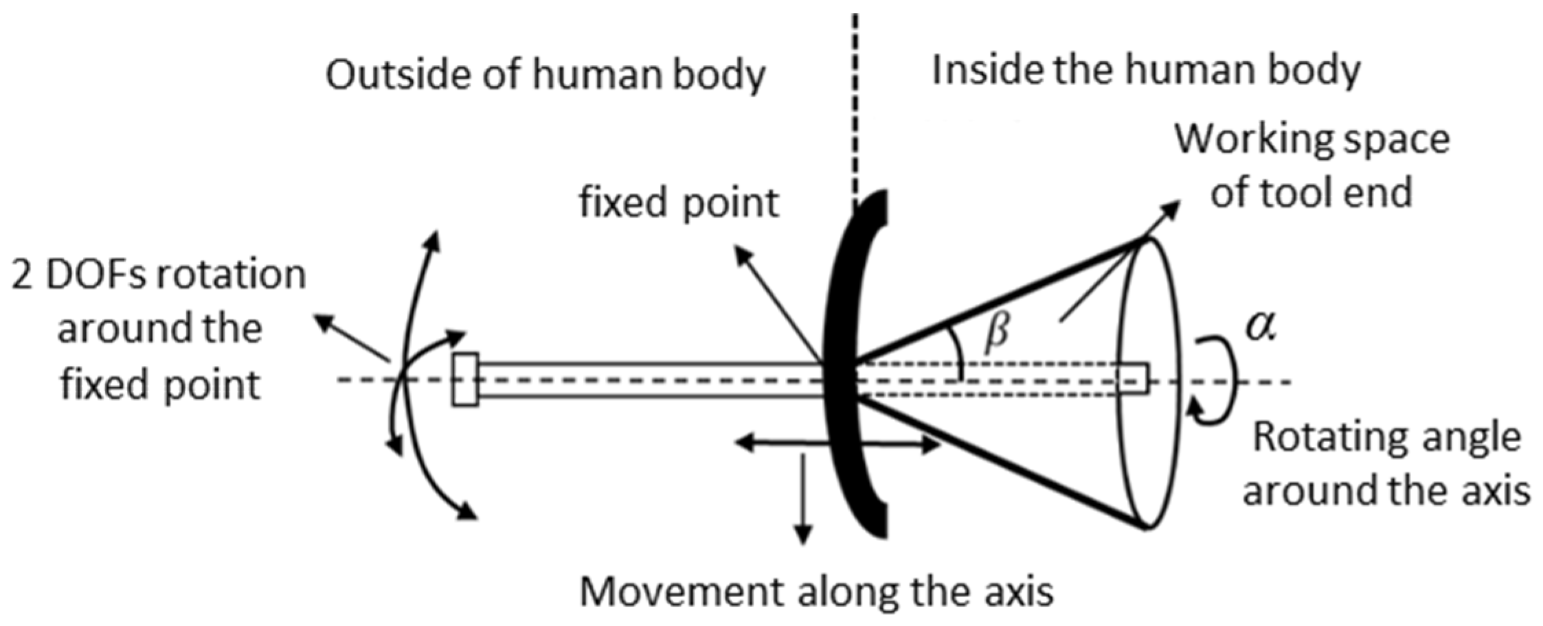
In the surgical robot, the surgical tool is finally regulated by the manipulator at the end of the slave system. During the whole process of the operation, the surgical tool takes the entry point as the support, and the relative position of the patient and the instrument base coordinate system is fixed. In order to prevent the surgical instrument from harming the human body, the position of the insertion fulcrum is approximately confined; this is called the remote center of motion or fixed point of mechanism. The end effector of the surgical manipulator moves to the infection site to realize the treatment of the pathological tissue. Due to the constraint of the fixed point, the surgical instrument loses two degrees of freedom during this movement. The remaining four degrees of freedom include two rotations around the fixed point, namely pitch and yaw; one rotation around the axis of the surgical instrument; and one slide motion along the axis of the surgical instrument. The remaining movements guarantee the end effector can move to any point within the working space. The rotation around the axis of the tool itself merely adjusts the direction of the surgical tool. It only achieves the posture adjustment and does not affect the absolute position of the end. Hence, the working space of the end effector is approximately formulated by a cone, and the fixed point is the vertex of the cone, as shown in Figure 1.
In Figure 1, the fixed point of the conical space is the necessary requirement for minimally invasive surgery, and the spatial size of the cone is the space that the surgical instrument must reach to carry out the operation. Taking the clinical surgery of benign prostatic hyperplasia into account, the working parameters given by the surgeon are analyzed and obtained for system design. The maximum yaw or pitch angle β is 45°, and the maximum insertion length is 200 mm. Due to the elasticity of human body tissue, the positioning error of the fixed point should be restricted to less than 5 mm. In clinical trials, 8 mm is the maximum acceptable error. If the size of the point distribution area exceeds this value, it will cause harm to the human urethra through which the tool is inserted.
2.2. Modeling of End Effector Posture
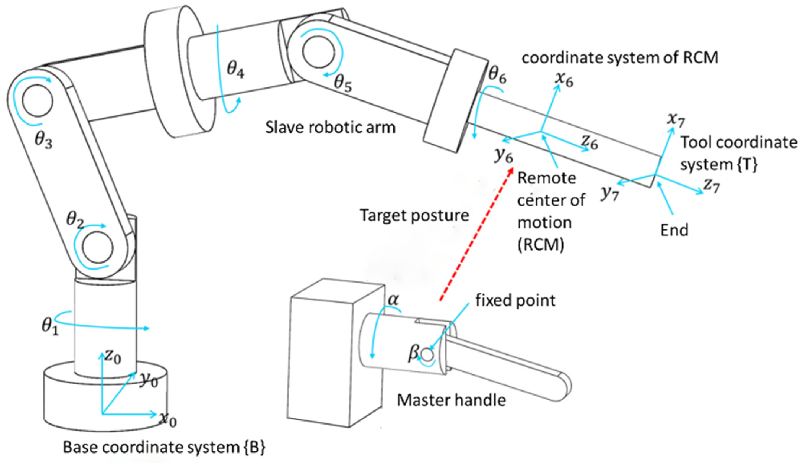
Supposing a robot with the configuration shown in Figure 2, where the surgical tool is handled by a serial manipulator, and the posture of the robot arm can be described by coordinate transformation. The coordinate system of the robot arm base is fixed as the reference that is the base coordinate system. The coordinate system of the end point of the robot arm is the tool coordinate system, and the coordinate system located at the remote center of motion is the RCM coordinate system. The master–slave robot configuration and corresponding coordinate system are shown in Figure 2. Driven by multiple rotational joints, the position and direction of the coordinate system attached to each link of the robotic arm are subject to change. The position is represented by the position vector of the origin of each coordinate system described in the base coordinate system, while the direction is expressed by the projection of the unit vector of each coordinate axis in the base coordinate system.
The transformation between the base coordinate system of the slave manipulator and the RCM coordinate system of the tool end effector shown in Figure 2 is expressed by the following matrix:
where is the projection of the x-axis unit vector of RCM coordinate system of the end effector on each axis direction of the base coordinate system, is the projection of the y-axis unit vector of RCM coordinate system of the end effector on each axis direction of the base coordinate system, is the projection of the z-axis unit vector of RCM coordinate system of the end effector on each axis of the base coordinate system, and is the position vector of the origin of the RCM coordinate system with respect to the base coordinate system. The first three columns of the matrix represent the posture of the surgical tool end, while the last column indicates the position coordinates of the remote center of motion generated by the slave manipulator for the surgical robot.
In this paper, the method of D-H is applied to establish the relationship between each joint coordinate system and surgical tool coordinate system. The transformation matrix describing the relation of the relative position of two coordinate systems next to each other is written as follows:
where is the transformation matrix and i = 1, …, 6. θi is the joint angle. αi is the rotation angle of the coordinate system. ai is the link length. di is the link offset.
3. Parameter Estimation by Simulation
3.1. Simulation Model Creation
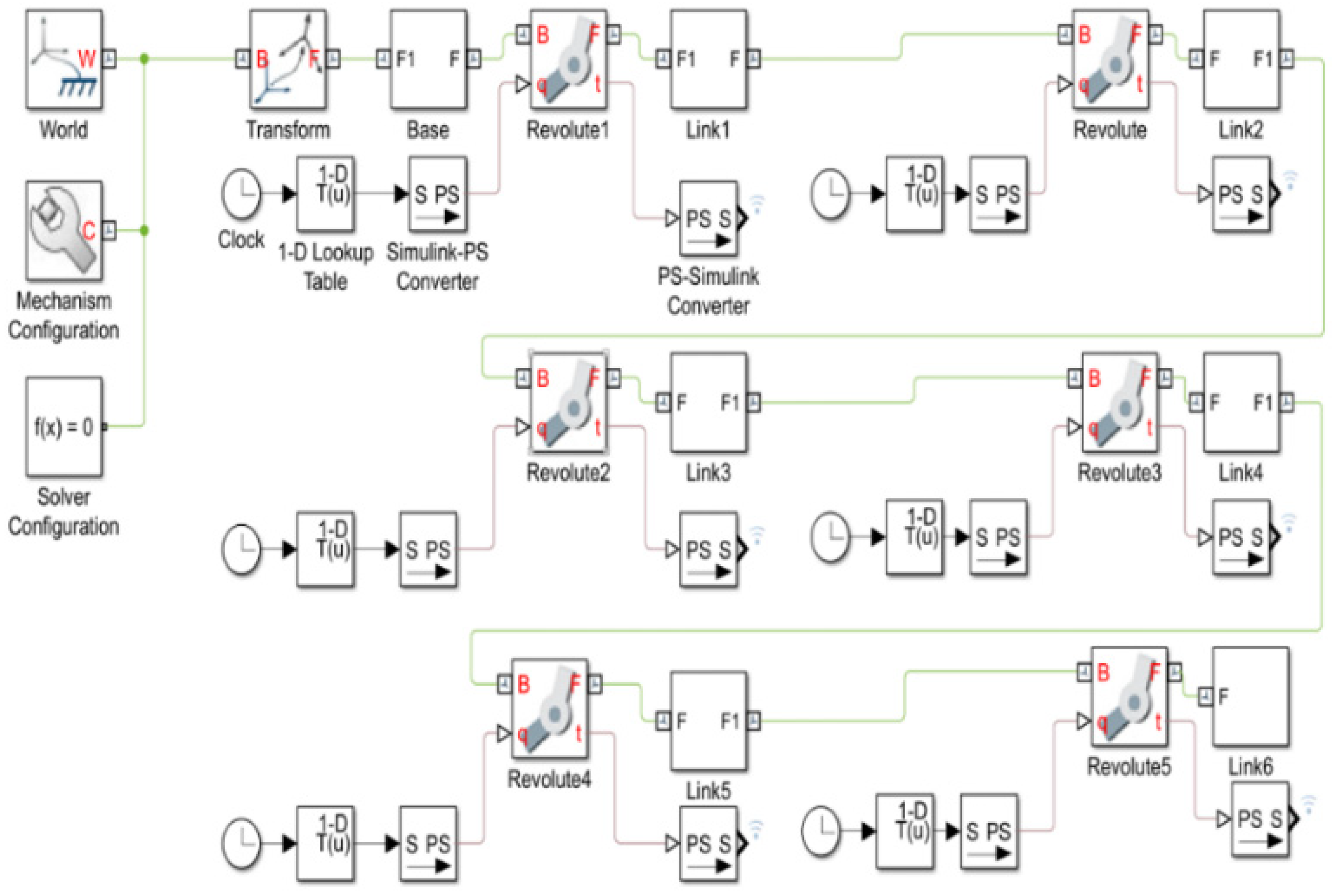
In order to finalize the manipulator design, the determination of joint torque and the corresponding electric motor selection are the important procedures. This can be realized with the help of virtual prototyping techniques. Modeling of inverse dynamics and simulation are conducted in MATLAB/Simulink environment as shown in Figure 3. In the simulation, the angular displacement of the six revolute joints of the virtual manipulator is set as external input of the model, and the rotation angles of the joints are calculated in advance by inverse kinematics equations and stored in a 1D lookup table. The inverse kinematics models are established following the way of dealing with the serial robotic arm by the Denavit–Hartenberg method (see [23] for details). The driving torque of the revolute joint is automatically calculated, and the result is output to the simulation data inspector for observation and postprocessing. The inverse dynamic simulation of the joint space is done to present the rotation angle of each joint of the manipulator, and the driving torque of each joint is calculated. Compared with the automatic calculation of the joint rotation angle through the inverse dynamic simulation model created in the Cartesian space, the model complexity is reduced. Thus, the dynamic simulation and virtual prototype building in this research are completed in the joint space.
3.2. Trajectory Planning
Like the industrial robot in the production line, the slave robotic arm should track the trajectory to manipulate the surgical tool. More specifically, the end effector must pass through the remote center of motion at all times. The results can not be achieved effectively by the point-to-point tracking motion control method. Thus, it is necessary to follow the specially controlled trajectory during the entire moving process of the robotic arm.
The movement of the surgical manipulator can be represented by the posture transformation of the tool coordinate system with respect to the base coordinate system. In the simulation, the coordinate of the remote center of motion with respect to the base coordinate system is (349.24, 0, 150). Combined with the working space of the surgical tool shown in Figure 1, the coordinates at the end of the robotic arm in the base coordinate system can be expressed as follows:
Trajectory planning is carried out for the condition that the slave manipulator operates itself without the participation of the master handle. The position coordinates of the end effector of the robotic arm at the initial stage are , and the coordinates at the final stage are . The fifth-order polynomial interpolation is adopted to plan the trajectory of the end position change in Cartesian space. For X, expressions are given as follows:
Accordingly, the speed can be obtained:
Finally, the acceleration featuring dynamics is
In simulation, the coordinate of point A is equal, the final position of point B is set to (370, 15, 150), and the running time s. In order to make the manipulator move smoothly without impact, let , , , and , and the trajectory of X can be calculated as follows:
In the same way, the trajectories of Y and Z can be planned as follows:
Through Equations (7)–(9) the end position coordinates of the end effector can be obtained. For further calculation, the parameters ,,,,, of inverse kinematics matrix in Equation (1) are required. The position vector from the fixed point to the end position coordinate is written into , and the distance from the tool end to the fixed point is
The posture parameters ,, of the end effector are the projection of the unit vector of the position vector in the base coordinate system, which is
The position parameters ,, are equal to the coordinates of the fixed point.
In addition, α and β shown in Figure 2 are zero and 45°. The last parameter to determine is the feed of the end effector along its own axis. The length of link 6 of the robotic arm named d6 is constantly equal to 260 mm, and it is divided into the parts located inside and outside of the body part. There exists a dynamic relation of “as one falls, another rises” for them during feeding movement, so we have
d6 = 260 − r
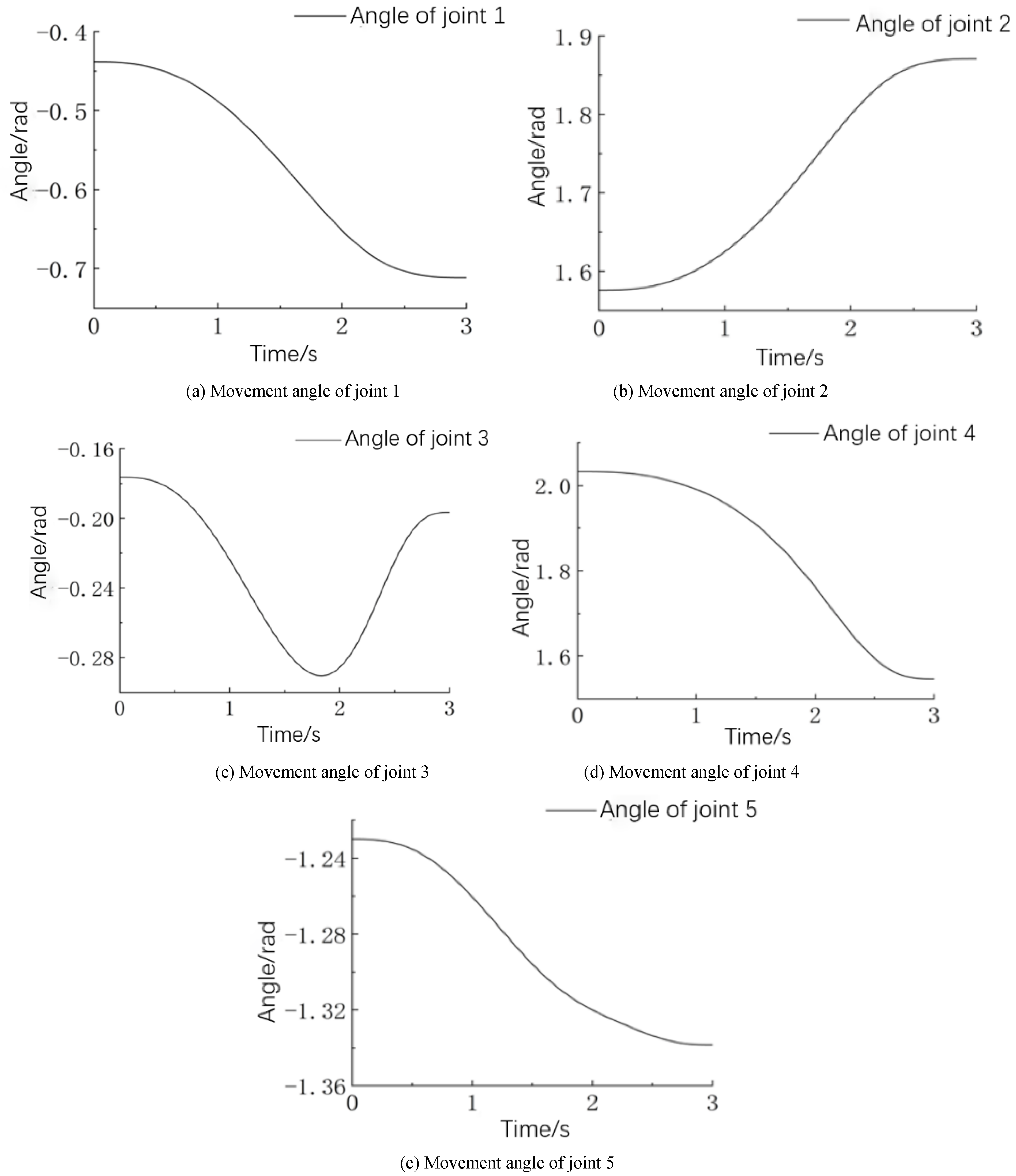
Substituting the parameters obtained through trajectory planning in Cartesian space into the inverse kinematics equations, the angle of the joint in motion can be calculated. The results obtained in the simulation are shown in Figure 4. It can be seen from the figures that the joints track the smooth motion trajectory, and no sudden change occurs throughout the orientation test process of the slave robotic arm.
3.3. Joint Dynamics Simulation
Now that we have determined the joint motion generated by tracking a given trajectory, it can be used to calculate the joint dynamics during operation. The data abstracted from the joint angle variation shown in Figure 4 were taken as the input of the dynamic simulation model of the manipulator by configuring the 1D lookup table in Figure 3. Virtual sensors for the measurement of angle, angular velocity, angular acceleration, and driving torque can be added to the rotary joints of the simulation model to observe the moving state and the joint driving parameters of the manipulator in real time.
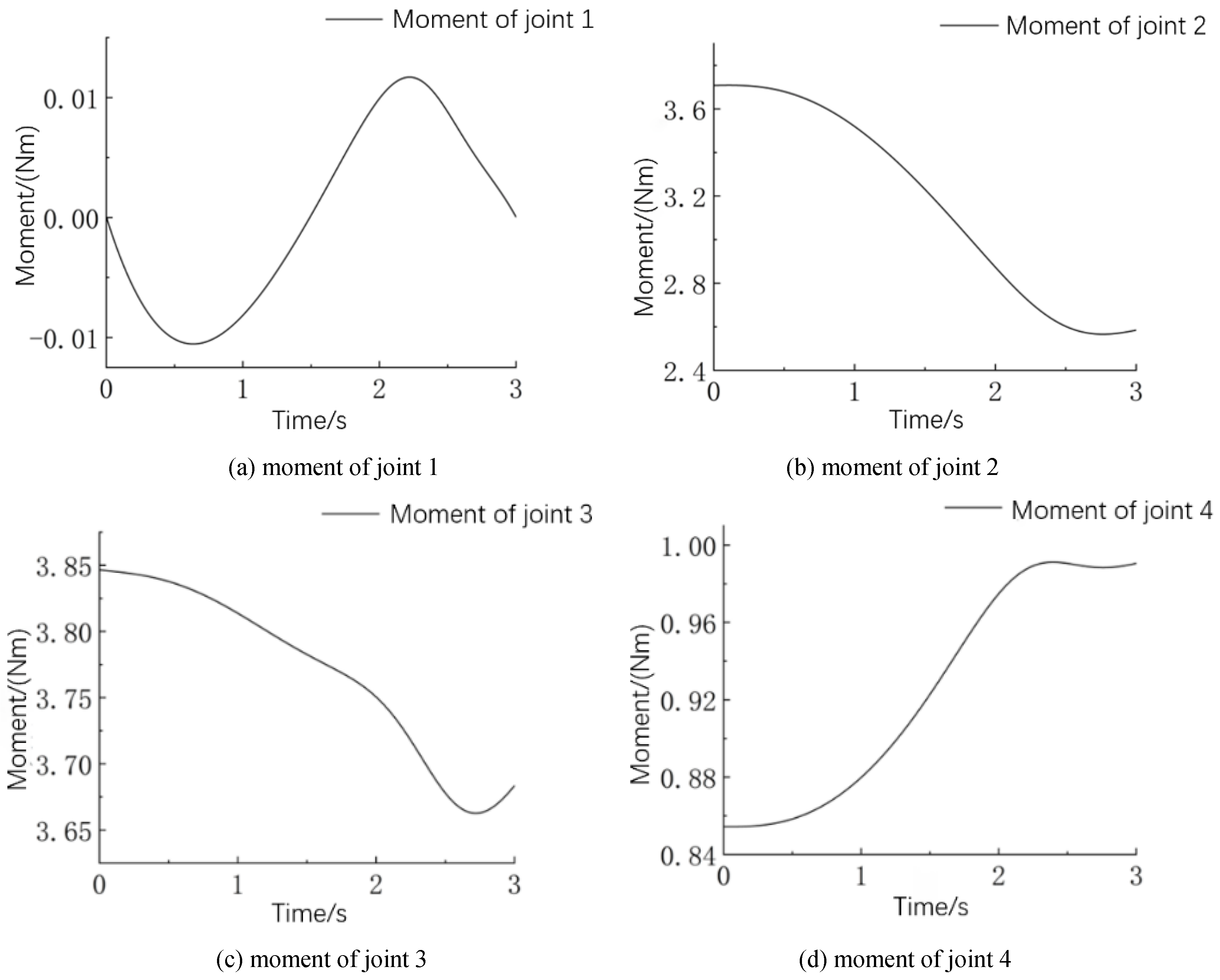
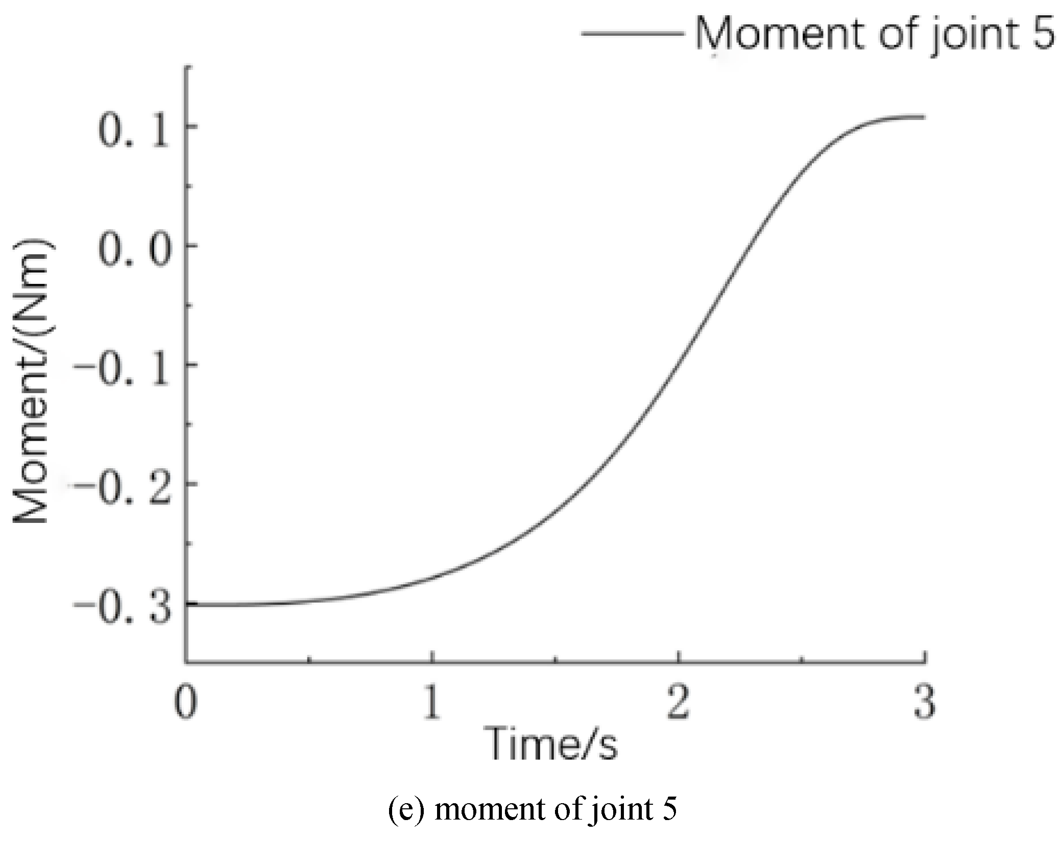
The torque variation of joint 1 to joint 5 is depicted in Figure 5. The torque of each joint changes smoothly in the presence of trajectory planning, effectively eliminating the adverse change in the motion of the robotic arm caused by load uncertainties. These results can be used as a reference for the electric motor selection for joint drive units. The appropriate motor was selected according to the maximum driving torque taking place in each curve, and it ensures that the selected motor can meet the power output requirements by considering the torque-speed characteristic. Moreover, taking into account the acceleration of each joint obtained in simulation, the relationship between the parameters of joint torque and acceleration reflects the nonlinearity that exists in the serial manipulator.
3.4. Structure Design of Surgical Slave Robotic Arm
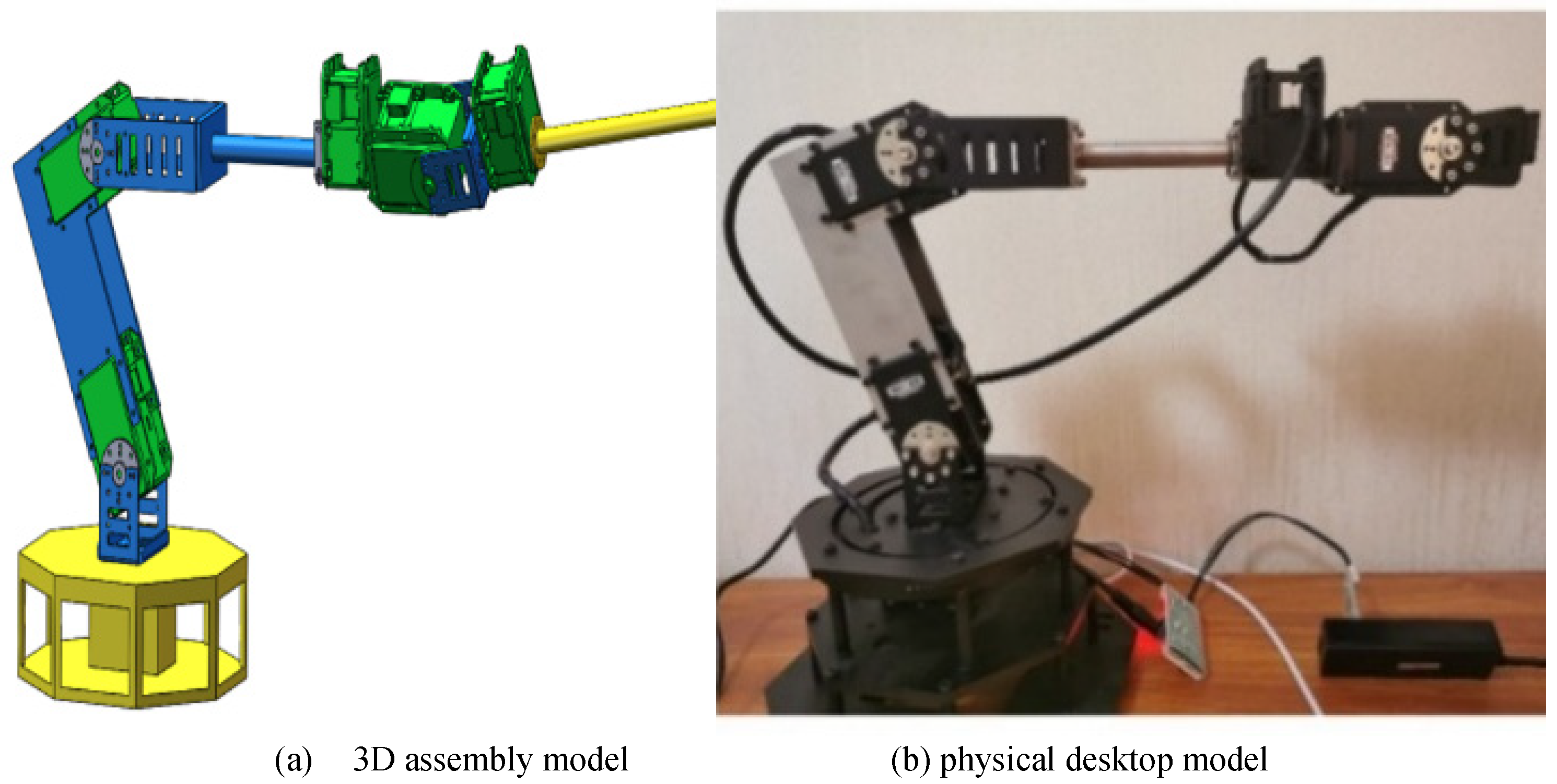
Once the joint torque parameter was known, the slave manipulator for the surgical robot could be designed in detail with reference to the serial industrial robotic arm. In order to achieve better performance in kinematics, the length of each link was determined by the optimization using a genetic algorithm [23]. In the dynamics simulation with the virtual prototype, the iterative optimization of motor selection and robotic arm design was carried out to guarantee the final performance. After determining the specific details, the surgical slave robotic arm was constructed in Solidworks software. The complete assembly model in 3D space is shown in Figure 6a. Considering the lightweight frame structure, the support link made with an aluminum alloy plate was used. The base was made of steel and covered a relatively large area in the horizontal plane to ensure stability. The physical model manufactured on the desktop is shown in Figure 6b. Six Dynamixel actuators composed of Maxon coreless DC motors were purchased and integrated into the joint module to fit the needs of drive, sensing, control, and networking.
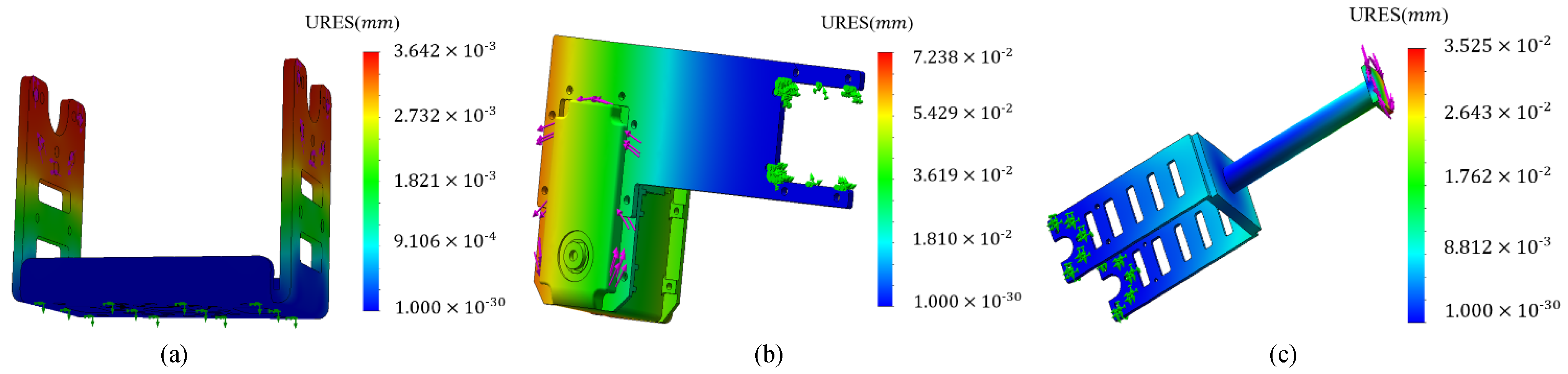
Since the rigidity of the structural frame is critical to the operation accuracy of the robotic arm, deformation under force action is analyzed through finite element analysis method. According to the analysis of error source contribution, three joints are sensitive to error transformation [23]. Joint connections approaching the base are taken into consideration, and the deformation shown in Figure 7 is obtained in the presence of joint torque loading. Figure 7a shows the component located on the base; its deformation is 3.6 μm at maximum. Figure 7b and Figure 7c show the deformation of joints 2 and 3; their maximum values are 72.3 and 35.2 μm, respectively. It can be concluded that the rigidity of the robotic arm only exerts a trifling influence on the precise movement.
4. Master–Slave Control Experiment
4.1. Master Mechanism Design
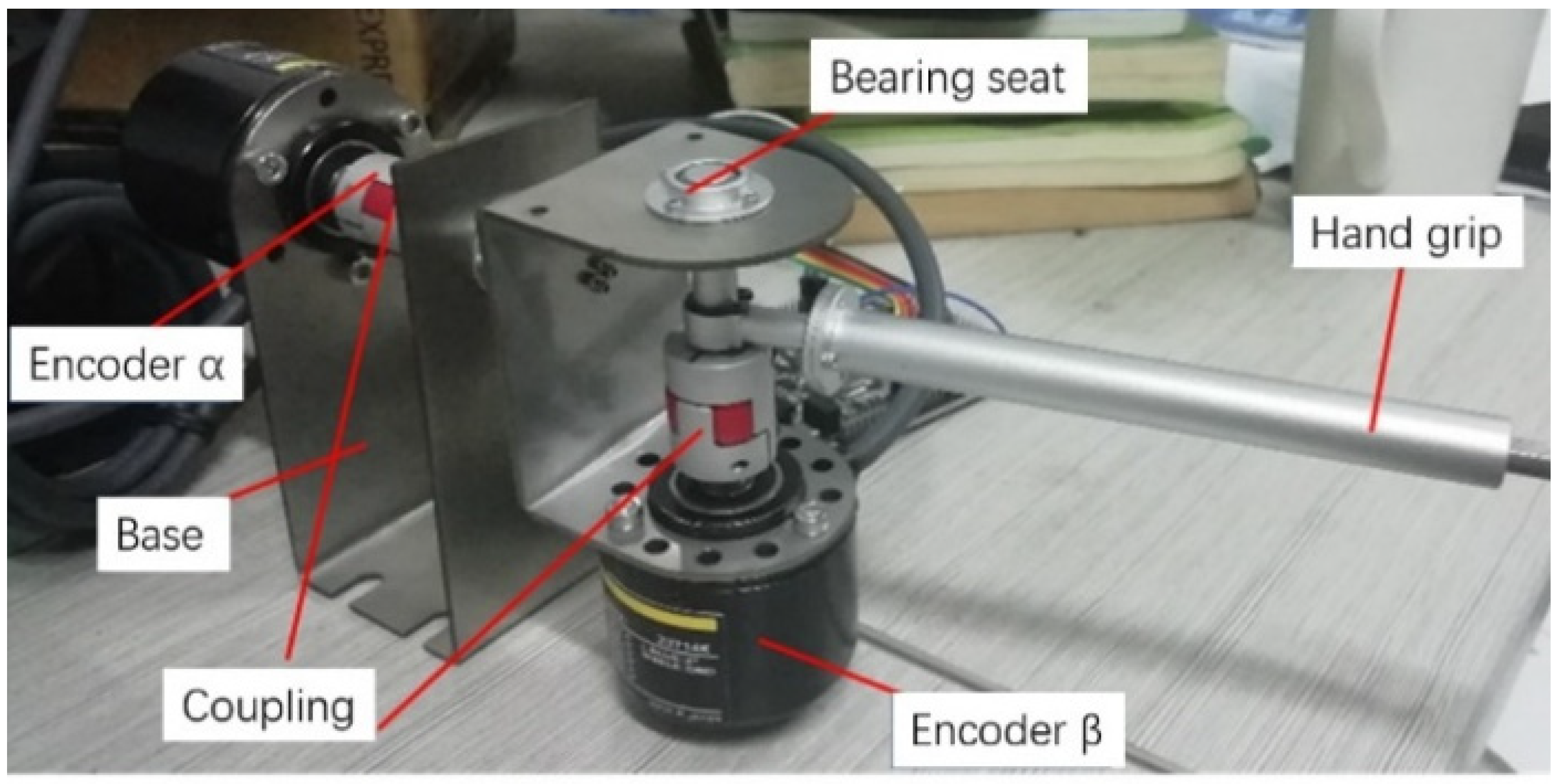
The manipulator at the master end of the surgical robotic system is developed to generate the command signal of the hand movement, as shown in Figure 8. Taking advantage of absolute master–slave control and incremental master–slave control modes, in this paper, the two degrees of freedom of the surgical tool rotation around the fixed point are regulated by absolute control mode, and the remaining rotation about the axis of the tool and the feed movement are implemented by the incremental control mode. In the mechanism, the encoder α detects the rotation angle α around the axis depicted in Figure 1, and the encoder β detects the rotation angle β around the fixed point in Figure 1. By establishing a spherical coordinate system, mathematical modeling of the tool end posture is realized. The rotation angle of the surgical robot arm around the axis of the end effector and the movement along the axis of the end effector are both incrementally tuned in the form of buttons. The movement variables corresponding to the above four degrees of freedom are taken as input commands for the motion control of the surgical slave manipulator.
4.2. Experiment and Discussion
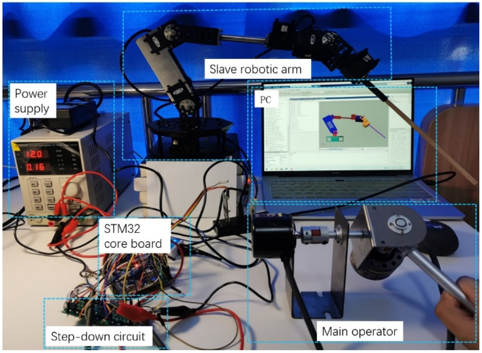
The experimental setup for testing the master–slave control performance is shown in Figure 9. The encoders at the master end record signals and send them to the microprocessor STM32, which is used for the posture control of the end effector of the surgical slave manipulator. Kinematics calculation and data acquisition are conducted in MATLAB/Simulink environment by interaction with STM32 in real time. After the signal is sent to the computer model, the master–slave control experiment is performed through the virtual prototype indirectly, and the relevant experimental data are collected simultaneously. In the experiment, because the integration coefficient is likely to be influenced by static error, PD control strategy is employed to deal with the trajectory tracking of the slave manipulator. The control law can be expressed as
where u(t) is the output of PD controller, Kp and Kd are the proportional and derivative coefficients of the PD controller, and e(t) is the error between the desired and the actual output values of the joints. The schematic diagram of the PD controller is illustrated in Figure 10, where θd and θ represent the desired angle and the actual angle of the control objective, respectively.
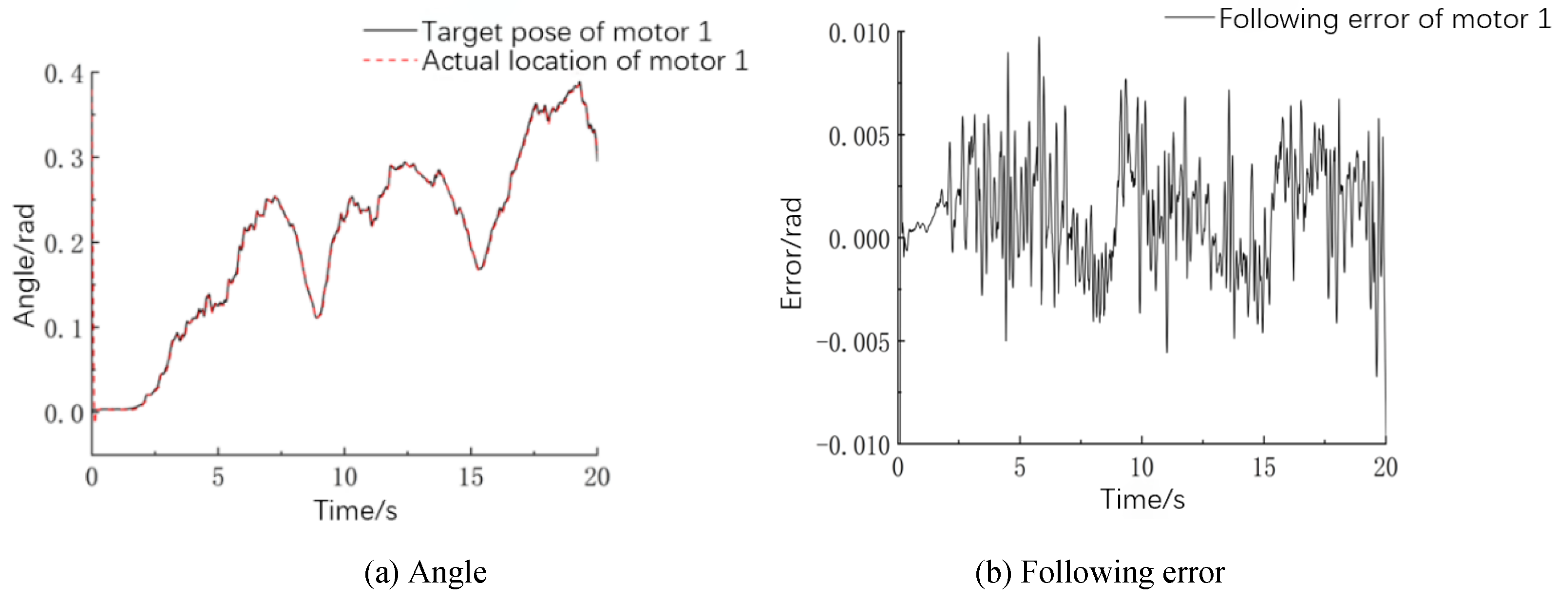
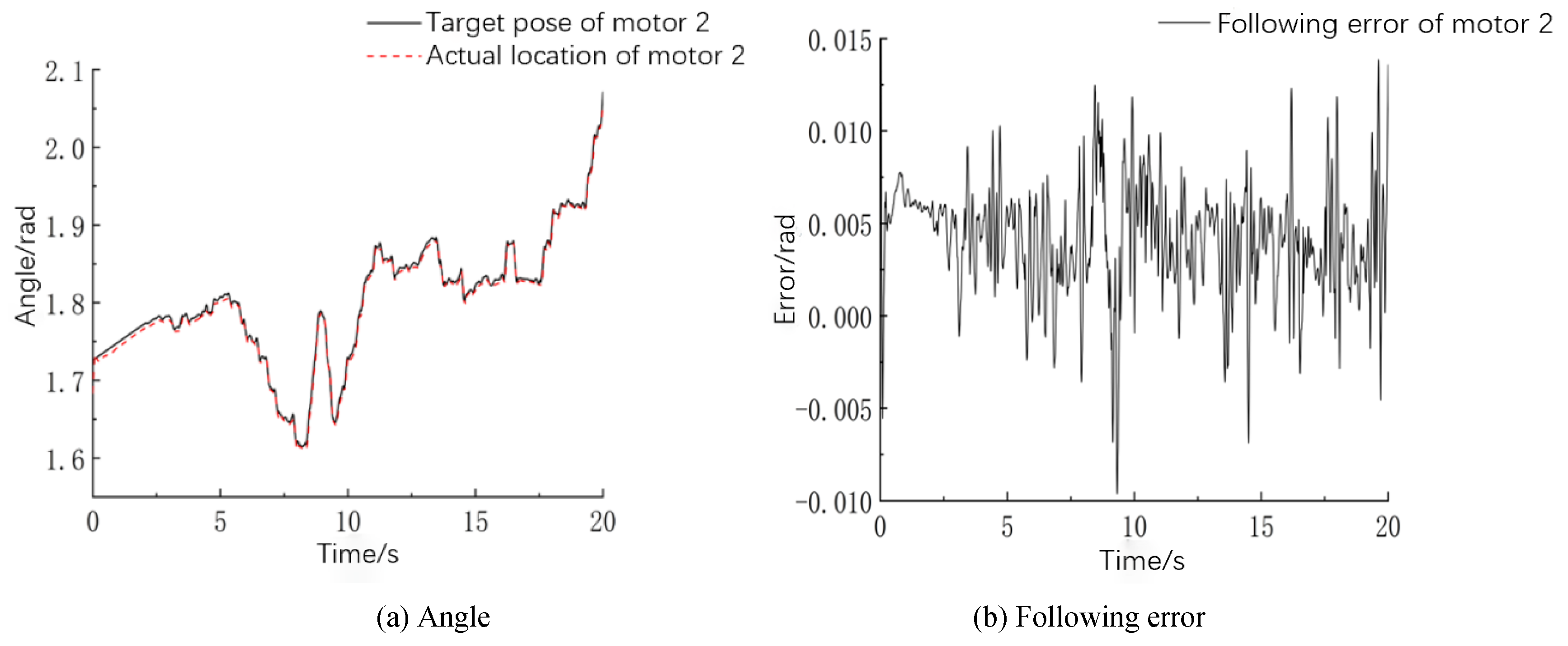
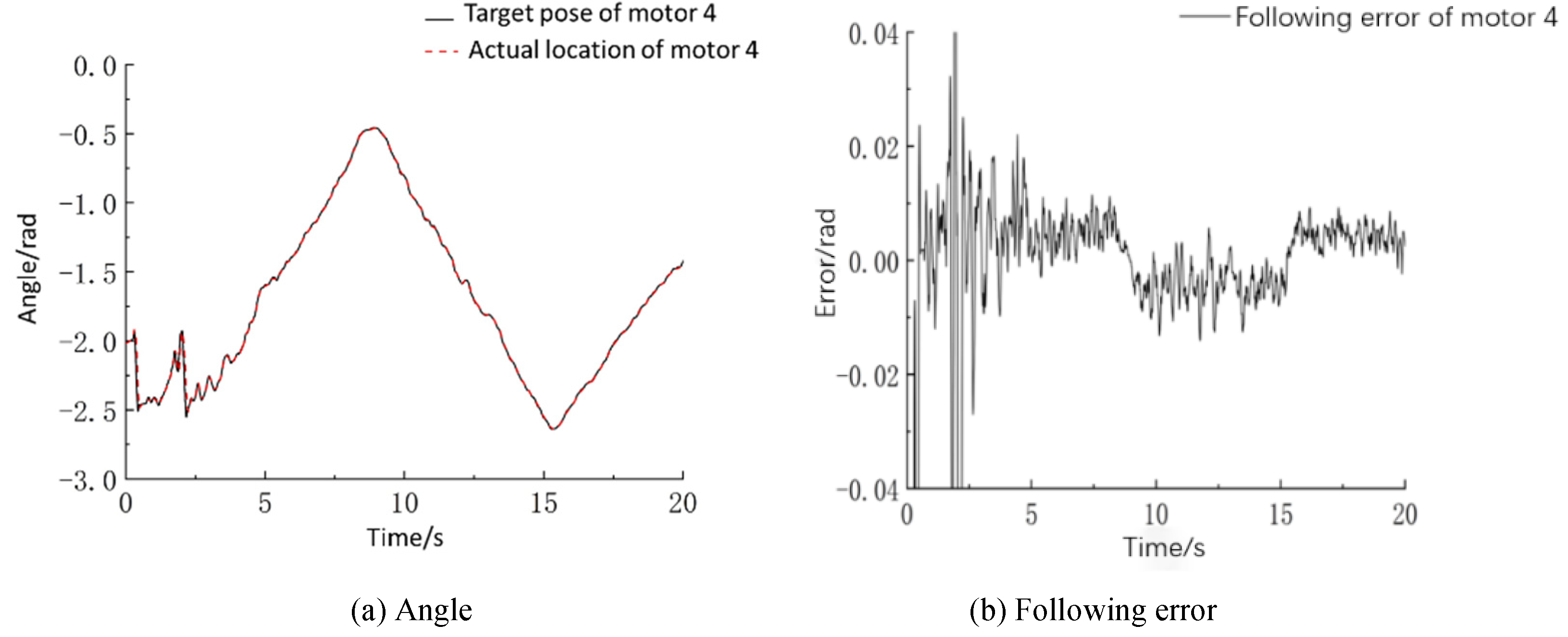
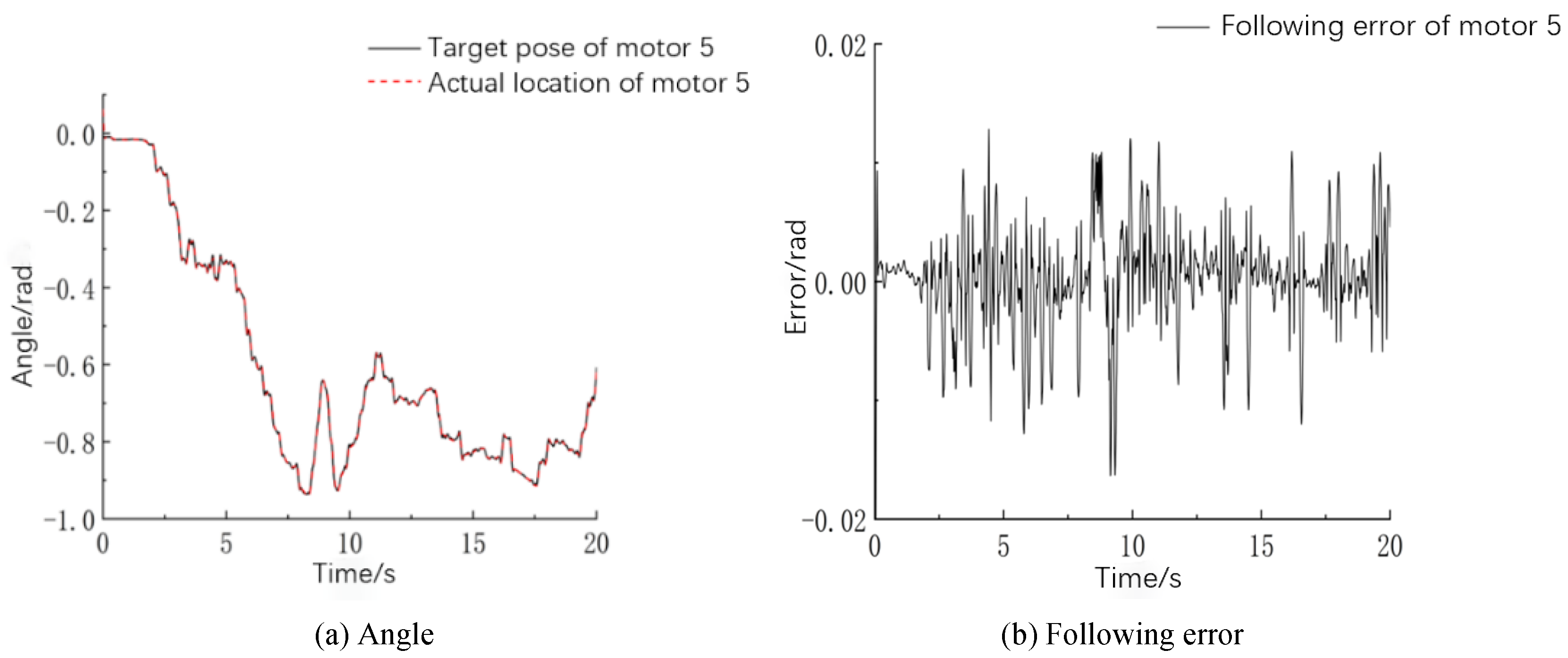
Since the motion of the end of the surgical robotic arm is a composition of movements generated by every joint, the angle change of five electric motors is a key parameter determining the characteristics of remote center motion. The trajectory-following curve and following error from motors 1 to 5 of the slave manipulator arm are shown in Figure 11, Figure 12, Figure 13, Figure 14 and Figure 15. The desired position of each joint is calculated by the inverse kinematics model, and the actual position is detected by the encoder attached to the motor. In order to make comparisons between the following characteristics of different motors, the average following error of each motor within a sampling period is formulated by the average absolute value of relative errors. It turns out that the average following errors of motors 1 to 5 are 0.18, 0.31, 0.34, 0.36, and 0.23°, respectively.
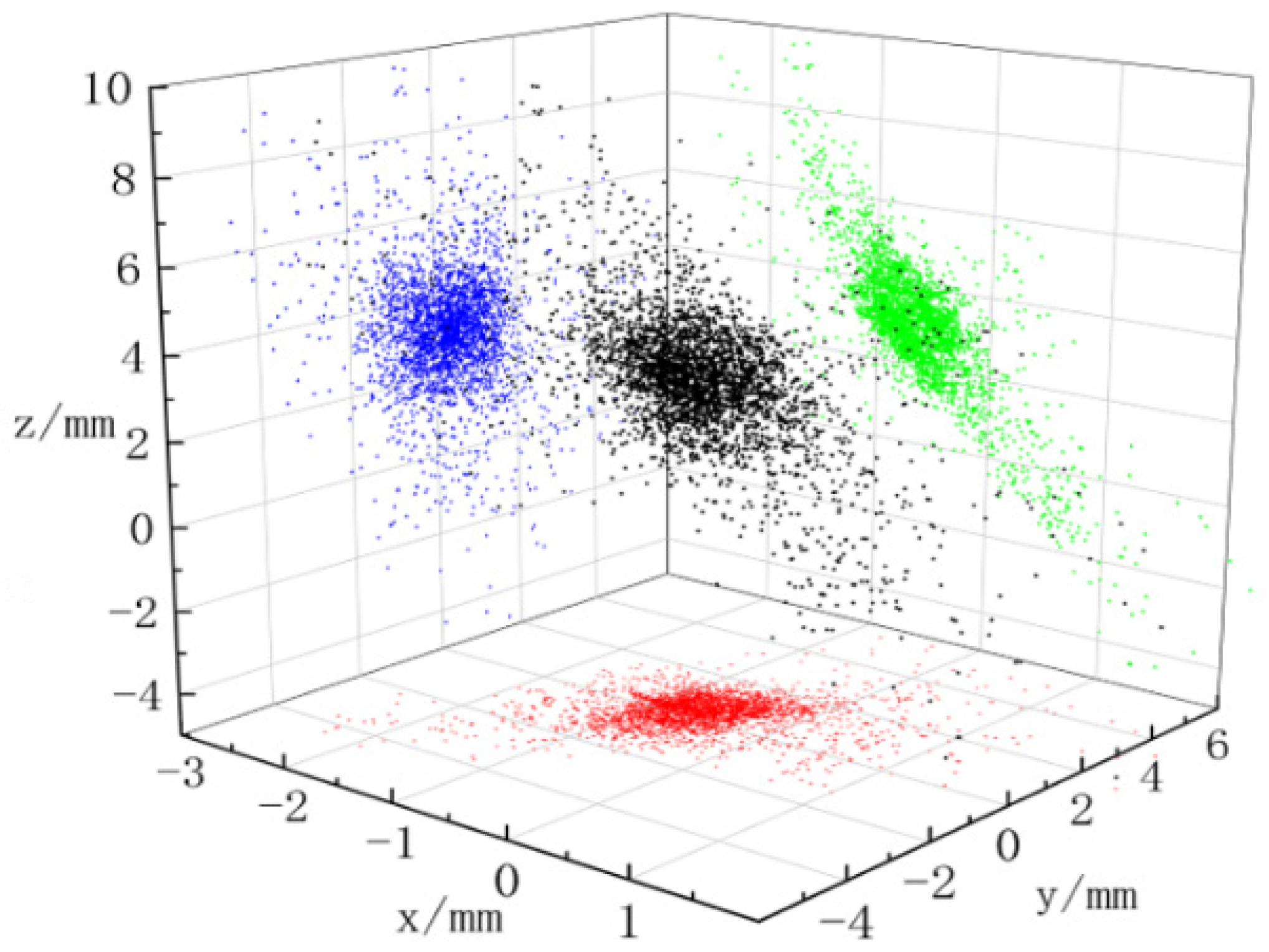
Combining the motion from motors 1 to 5, the posture of the surgical tool end can be plotted in three-dimensional space. The scatter diagram of the fixed point distribution extracted from the end effector of the slave manipulator and the projection on three coordinate planes are displayed in Figure 16. In the figure, the projection of the end point of the robotic arm in the x–y, x–z, and y–z planes is indicated with red, blue, and green dots, and the black dots symbolize the spatial location.
Because the feed of the surgical tool along its axis is difficult to measure in this experiment, the ideal incremental input signal is used for subsequent data processing. The fixed point position in the coordinate system is calculated by pose matrix transformation. The average errors of the fixed point of the end effector falling in the x, y, and z directions are calculated to be 0.73, 0.81, and 3.14 mm, and the maximum errors are 2.49, 5.63, and 9.58 mm. In the PD control system, because the robot arm is subject to gravity, the position error of the fixed point in the z-axis direction is greater than that in other directions. Since the body tissue is soft and flexible enough, position error at the fixed point is basically within the acceptable range. Further analysis on point distribution shows that the points with position error less than 5 mm account for 91.96%. Statistically, over 99% of working conditions for surgery can be covered by this range.
The tracking error of the end of the slave robotic arm obtained with the PD control mode is decomposed into three components and shown in Figure 17. The theoretical coordinates and actual coordinates of the end are calculated by matrix transformation. The calculated average errors in the x, y, and z directions are 0.71, 0.76, and 2.89 mm. Similar to the case of the fixed point positioning, the error in the z-axis direction influenced by gravity is larger than that in the other directions. The comprehensive tracking error of the end of the slave robotic arm is 3.18 mm on average. The error in the z-direction is nearly 6 mm, approximately equal to the results obtained by Niccolini [24]. In contrast, the control architecture involved in this paper is much less complicated.
In robot-assisted surgery, the position of the tool end is manipulated by the doctor’s hands operating master handles. The doctor adjusts the target position freely according to the surgical scene. Therefore, the positioning accuracy of the end remaining stationary should be paid more attention to than that of the following motion. Under the circumstances, the doctor holds the tool end in position and implements cutting by scalpel or burning by laser when the target is found. By regulating the movement of the master handle to a certain position, the button is used to achieve fine-tuning of the control increment. At this time, the data of the motor encoder are collected to obtain the actual rotation angle of the motor and the joint.
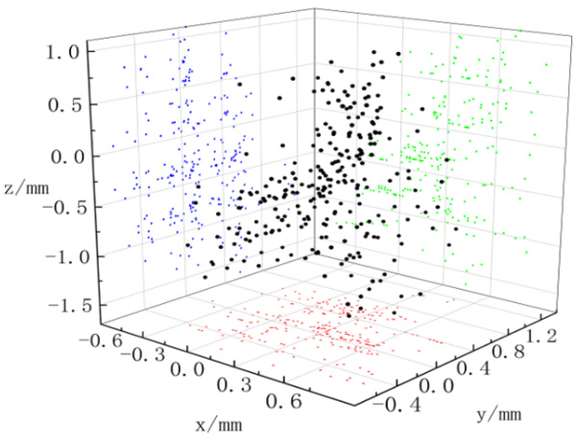
To achieve the better performance of the master–slave control system in the tool end positioning, feedforward control action is proposed to compensate for the influence of gravity. The theoretical position of the robotic arm is calculated by the solution of direct kinematics using the input control command. The actual position is calculated by the solution of direct kinematics with the angle feedback from the motor encoder. Repeating the tool end positioning experiment for randomly holding 20 different positions over and over again, the absolute positioning error is obtained as shown in Figure 18. The error of the end of the robotic arm in the x, y, and z directions is indicated with blue, green, and red dots, and the black dots symbolize the total error.
In Figure 18, the average errors of the end of the robotic arm in the x, y, and z directions are 0.33, 0.24, and 0.54 mm, and the maximum errors are 0.87, 1.17, and 1.63 mm. The total positioning error of the end of the robotic arm is 0.75 mm on average, and the maximum positioning error on average is 1.7 mm. Dots with an error of less than 1 mm account for 80.79%, and those with an error of less than 1.5 mm account for 99.83%. The result is similar to the tool end positioning error of 1.02 mm obtained by David when investigating the Da Vinci surgical robot system through experiments [25]. This accuracy level definitely meets the requirements of the most removal-orientated surgery in surgical tool positioning. The developed robotic arm is very well suited for applications in widely used urological surgery, such as that for benign prostatic hyperplasia.
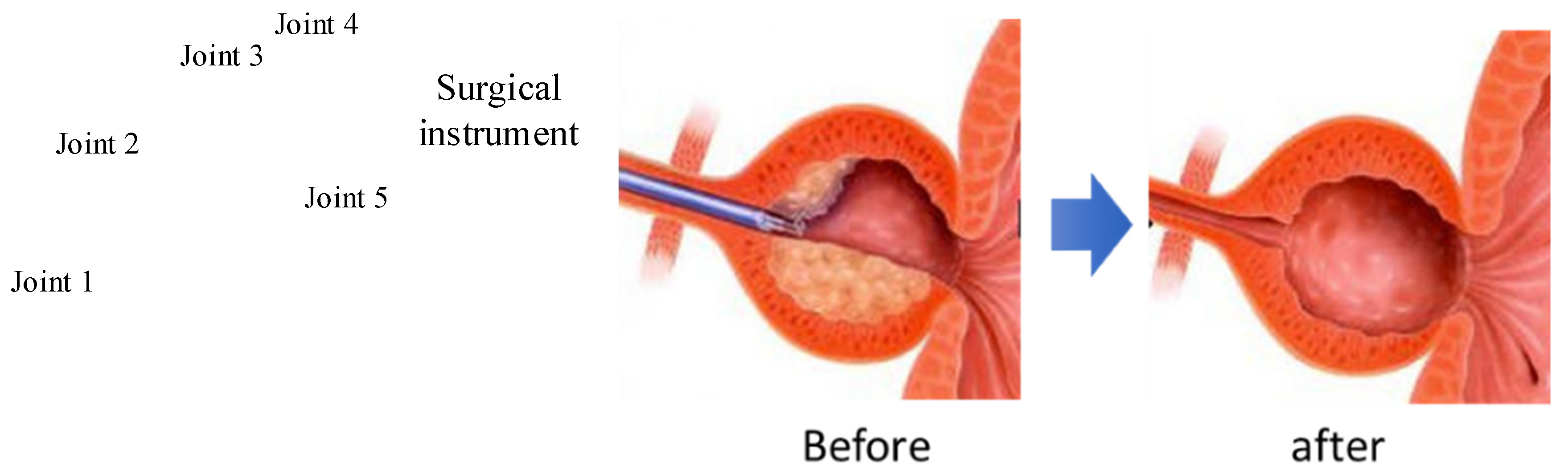
To further discuss the applicability of the surgical robot proposed above, surgery for benign prostatic hyperplasia (BPH) treatment is taken as an example to analyze the motion performance of the surgical instrument. As shown in Figure 19, tissue cutting to form a hollow sphere is required by surgery. The motion performed by the surgical robot proposed in this paper satisfied the requirements exactly. In fact, the support point of the surgical instrument is fixed virtually, and its flexible support definitely allows a relative displacement deviation. With this practical condition, the robot can fulfill the task in surgery as expected.
5. Conclusions
This paper deals with the design, modeling, prototyping, and control of a serial robotic arm for the potential application in robot-assisted surgery. It is composed of many joints mounted in series with the surgical tool end performing both a translational workspace and a cone-shaped orientation workspace. It should be noted that the joints dynamics can be determined by coping with inverse kinematics-based trajectory planning of the tool end in the virtual prototype modeling environment. As a consequence, the overall electric motor drive system is parameterized for design, and its comprehensive performance in motion is predicted accurately.
The heterogeneous master–slave control architecture is adopted to build the surgical robot system by developing a master handle. The performances of the master–slave prototype were experimentally evaluated by measuring the positioning error of the virtual fixed point and the surgical tool end along the planned trajectory. It appears that the average positioning error of the apex of cone-shaped space is about 3.4 mm, of which the component in the z-direction is much larger than the components in the other two directions. By compensating for the influence of gravity, the maximum positioning error of the tool end reaches 1.7 mm. Future work will focus on reducing the time delay of the control signal transmission of the master–slave architecture thanks to an improved design of the control algorithm and better management of the data acquisition in real time.
Author Contributions
H.S.: conceptualization, simulation, validation, original draft; Q.L.: discussion, resources, experimentation, editing; X.M.: supervision, resources. All authors have read and agreed to the published version of the manuscript.
Funding
The financial support of the National Natural Science Foundation of China (Grant No. 51675400) is gratefully acknowledged.
Institutional Review Board Statement
Not applicable.
Informed Consent Statement
Not applicable.
Conflicts of Interest
There are no conflicts of interest.
References
- Carlos, E.D.; Roemi, F.; Manuel, A. State of the art in robots used in minimally invasive surgeries. Natural Orifice Transluminal Surgery (NOTES) as a particular case. Ind. Robot 2015, 42, 508–532. [Google Scholar]
- Lum, M.J.H.; Rosen, J.; Sinanan, M.N.; Hannaford, B. Optimization of a spherical mechanism for a minimally invasive surgical robot: Theoretical and experimental approaches. IEEE Trans. Biomed. Eng. 2006, 53, 1440–1445. [Google Scholar] [CrossRef] [PubMed]
- Jin, C.; Wang, T. Progress of Da Vinci robot in surgical operation of gastric cancer. J. Clin. Surg. 2020, 28, 991–994. [Google Scholar]
- Locke, R.C.O.; Patel, R.V. Optimal remote center-of-motion location for robotics-assisted minimally-invasive surgery. In Proceedings of the 2007 IEEE International Conference on Robotics and Automation, Rome, Italy, 10–14 April 2007; pp. 1900–1905. [Google Scholar]
- Hagn, U.; Nickl, M.; Stephan, J. The DLR MIRO: A versatile lightweight robot for surgical applications. Ind. Robot 2008, 35, 324–336. [Google Scholar] [CrossRef] [Green Version]
- Allett, S.G.; Rossitto, C.; Cianci, S. The Sen-hance™ surgical robotic system (‘Senhance’) for total hysterectomy in obese patients: A pilot study. J. Robot. Surg. 2017, 12, 229–234. [Google Scholar] [CrossRef]
- Aksungur, S.; Aydin, M.; Yakut, O. Real-time PID control of a novel RCM mechanism designed and manufactured for use in laparoscopic surgery. Ind. Robot 2019, 47, 153–166. [Google Scholar] [CrossRef]
- Kuo, C.H.; Dai, J.S.; Dasgupta, P. Kinematic design considerations for minimally invasive surgical robots: An overview. Int. J. Med. Robot. Comput. Assist. Surg. 2012, 8, 127–145. [Google Scholar] [CrossRef]
- Liu, S.T.; Harewood, L.; Chen, B.; Chen, C. A skeletal prototype of surgical arm based on dual-triangular mechanism. Mech. Robot. 2016, 8, 041015. [Google Scholar] [CrossRef]
- Guo, L.J.; Shi, H.; Mei, X.S. Implementation of fixed point of minimally invasive surgical robot: A survey. J. Adv. Manuf. Sci. Technol. 2021, 1, 2020003. [Google Scholar]
- Xue, R.F.; Du, Z.J.; Yan, Z.Y.; Ren, B.Y. An estimation method of grasping force for laparoscope surgical robot based on the model of a cable-pulley system. Mech. Mach. Theory 2019, 134, 440–454. [Google Scholar] [CrossRef]
- Jin, S.; Lee, S.K.; Lee, J.; Han, S. Kinematic model and real-time path generator for a wire-driven surgical robot arm with articulated joint structure. Appl. Sci. 2019, 9, 4114. [Google Scholar] [CrossRef] [Green Version]
- Wang, H.; Wang, H.; Quan, L. Smooth point-to-point trajectory planning for industrial robots with kinematical constraints based on high-order polynomial curve. Mech. Mach. Theory 2019, 139, 284–293. [Google Scholar] [CrossRef]
- Zhao, B.L.; Nelson, C.A. Estimating tool–tissue forces using a 3 degree-of-freedom robotic surgical tool. J. Mech. Robot. 2016, 8, 051015. [Google Scholar] [CrossRef] [PubMed] [Green Version]
- Agarwal, P.; Neptune, R.R.; Deshpande, A.D. A simulation framework for virtual prototyping of robotic exoskeletons. Biomech. Eng. 2016, 138, 061004. [Google Scholar] [CrossRef] [PubMed]
- Kurc, K.; Szybicki, D.; Burghardt, A.; Muszyńska, M. The application of virtual prototyping methods to determine the dynamic parameters of mobile robot. Open Eng. 2016, 6, 55–63. [Google Scholar] [CrossRef]
- Yue, L.; Cao, Y.; Wang, S. Proportional coefficient analysis of master-slave robot system in workspace. Mech. Sci. Technol. 2007, 26, 803–807. [Google Scholar]
- Li, K.; Ji, S.; Niu, G.; Ai, Y.; Pan, B.; Fu, Y. Master-slave control and evaluation of force sensing for robot-assisted minimally invasive surgery. Ind. Robot Int. J. Robot. Res. Appl. 2020, 47, 903–914. [Google Scholar] [CrossRef]
- Guo, S.; Wang, Y.; Xiao, N. Study on real-time force feedback for a master–slave interventional surgical robotic system. Biomed. Microdevices 2018, 20, 37. [Google Scholar] [CrossRef]
- He, C.Y.; Huang, L.; Yang, Y. Research and realization of a master-slave robotic system for retinal vascular bypass surgery. Chin. J. Mech. Eng. 2018, 31, 78. [Google Scholar] [CrossRef]
- Yu, H.; Wang, H.; Chang, J.; Niu, J.; Wang, F.; Yan, Y.; Tian, H.; Fang, J.; Lu, H. A novel vascular intervention surgical robot based on force feedback and flexible clamping. Appl. Sci. 2021, 11, 611. [Google Scholar] [CrossRef]
- Du, Z.J.; Liang, Y.L.; Yan, Z.Y.; Sun, L.N.; Chen, W. Human-robot interaction control of a haptic master manipulator used in laparoscopic minimally invasive surgical robot system. Mech. Mach. Theory 2020, 156, 104132. [Google Scholar] [CrossRef]
- Li, J.; Shi, H.; Yang, L. Inverse kinematics analysis, size optimization and error analysis of urology surgical manipulator. In Proceedings of the IEEE Biomedical Engineering International Conference, Chiang Mai, Thailand, 21–24 November 2018. [Google Scholar]
- Niccolini, M.; Petroni, G.; Menciassi, A. Real-time control architecture of a novel single-port laparoscopy bimanual robot (SPRINT). In Proceedings of the IEEE International Conference on Robotics and Automation, Saint Paul, MN, USA, 14–18 May 2012; pp. 3395–3400. [Google Scholar]
- David, S.D.; Kwartowitz, M. Toward image-guided robotic surgery determining intrinsic accuracy of the da Vinci robot. Int. J. Comput. Assist. Radiol. Surg. 2006, 1, 157–165. [Google Scholar]
Figure 1.
Movement of surgical instruments.

Figure 2.
Master–slave robot configuration.

Figure 3.
Simulation model of the surgical manipulator in joint space.

Figure 4.
Joint motion angle calculated by inverse kinematics.

Figure 5.
Driving torque of each joint of the surgical manipulator.


Figure 6.
The finalized slave robotic arm.

Figure 7.
Deformation of mechanical frames of the robotic arm.

Figure 8.
The physical object of the master surgical manipulator.

Figure 9.
Master–slave control experimental setup.

Figure 10.
Block diagram of the PD control system.

Figure 11.
Trajectory-following results of motor 1.

Figure 12.
Trajectory-following results of motor 2.

Figure 13.
Trajectory-following results of motor 3.

Figure 14.
Trajectory-following results of motor 4.

Figure 15.
Trajectory-following results of motor 5.

Figure 16.
Distribution and plane projection of fixed point position.

Figure 17.
Tracking error of the surgical tool end in different directions.

Figure 18.
Stationary positioning error of surgical tool end.

Figure 19.
Possible application of surgical tool in BHP surgery.

Publisher’s Note: MDPI stays neutral with regard to jurisdictional claims in published maps and institutional affiliations. |
© 2021 by the authors. Licensee MDPI, Basel, Switzerland. This article is an open access article distributed under the terms and conditions of the Creative Commons Attribution (CC BY) license (https://creativecommons.org/licenses/by/4.0/).
Share and Cite
MDPI and ACS Style
Shi, H.; Liu, Q.; Mei, X. Accurate Parameter Estimation for Master–Slave Operation of a Surgical Robot. Machines 2021, 9, 213. https://doi.org/10.3390/machines9100213
AMA Style
Shi H, Liu Q, Mei X. Accurate Parameter Estimation for Master–Slave Operation of a Surgical Robot. Machines. 2021; 9(10):213. https://doi.org/10.3390/machines9100213
Chicago/Turabian StyleShi, Hu, Qingxin Liu, and Xuesong Mei. 2021. "Accurate Parameter Estimation for Master–Slave Operation of a Surgical Robot" Machines 9, no. 10: 213. https://doi.org/10.3390/machines9100213
Note that from the first issue of 2016, this journal uses article numbers instead of page numbers. See further details here.