1. Introduction
The purpose of Smart Fixed Wing Aircraft Integrated Technology Demonstrator (SFWAITD) from the FP7 Clean Sky program [
1] is to boost innovative technologies, concepts, and capabilities able to significantly decrease the consumption and oil contamination levels in aircraft systems. This program has among its main objectives the replacement of current hydraulic mechanisms for flaps and aircraft control surfaces for fully electrical technologies.
One of the principal concerns in the development of these electrical actuators is the reliability of the system against possible overloads which could cause serious self-damages in the structure. Up to now, two kinds of systems could be implemented to tackle this problem: mechanical conventional torque limiters and electrical overload control.
Conventional torque limiters based on fuse and/or friction have very low reliability and require continuous maintenance and replacement in case of overload. Besides, the debris generated in their friction disk are also problematic as the whole gearbox must be compact and surrounded by an oil bath. Meanwhile, electrical overload control requires additional electric elements and sensors with a response time that may be too high for a safe prevention of damage. Moreover, neither of them prevent damages due to jamming in intermediate positions of the kinematic chain. Therefore, there is a clear need for a new kind of torque limitation able to operate under any circumstance in the new aircraft electrical systems [
2,
3,
4,
5].
The solution proposed in this paper is based on a contactless magnetomechanical technology with the following main advantages: no friction, no power losses or heat generation by friction, no need for lubrication, reduced maintenance (no need of oil replacements), wider operational temperature ranges (no lubricant evaporation or freezing), overload protection (under an event of overload the magnet simply slides), through-wall connection (decoupling of thermal and electrical paths and environmental isolation), larger operative speeds (more efficient operative conditions), and ultralow noise and vibrations (no contact or noise generation). It is easy to anticipate the major step forward that contactless technology can bring to common industrial applications. For instance, one of the most important breakthroughs would be the reduction of noise and vibration in aerospace applications [
6,
7,
8].
More specifically, the aeronautical magnetic torque limiter hereby presented is intended to be operated in line with a mechanical gearbox between the first and the second reduction stage in the electromechanical actuator for flaps control. The reduction box must integrate a torque limiter function and filter out mechanical vibrations of its environment. Magnetic torque limiters provide a degree of torsional elasticity that can be used to reduce the transmission of torsional vibrations. The aeronautical magnetic torque limiter is designed not to emit any kind of magnetic field around it. It does not dissipate any kind of power while engaging (applied torque below limit). A main and unique feature of magnetic torque limiters is that they do not suffer wear or fatigue, independently of the times they act, when limiting the torque, increasing their reliability and requiring no maintenance.
This work describes the design, prototype, and performance test, according to RTCA-DO-160E, of an aeronautical magnetic torque limiter. The results show correct continuous transmission operation (2250 rpm and 24 Nm) from −50 °C to +90 °C. It also demonstrates its capability for overload protection, reaching more than 200 jamming/overload events without damage and without the need of maintenance.
2. Design and Method
The aeronautical magnetic torque limiter is composed of two elements with relative motion among them. The input element consists on a thin disk with a set of magnets configured with alternative magnetic polarization. The output element is composed of two parallel disks above and below the input element disk, with the same number of magnets.
Figure 1, extracted from the patent [
9], shows the kind of meshing that appears between the magnets, but in this figure a magnetic gear is shown and not a 1:1 coupling.
Magnets tend to be aligned since magnetic flux circuit needs to be closed. When there is some relative motion between input and output element, the repulsion or attraction that appears between input and output magnets generates a force that contributes to the total torque transmitted from the input to the output element. If the load torque is larger than the maximum transmittable torque, the input magnets simply slide or “jump” to the next pair of dipoles without damage neither in the input side nor in the output.
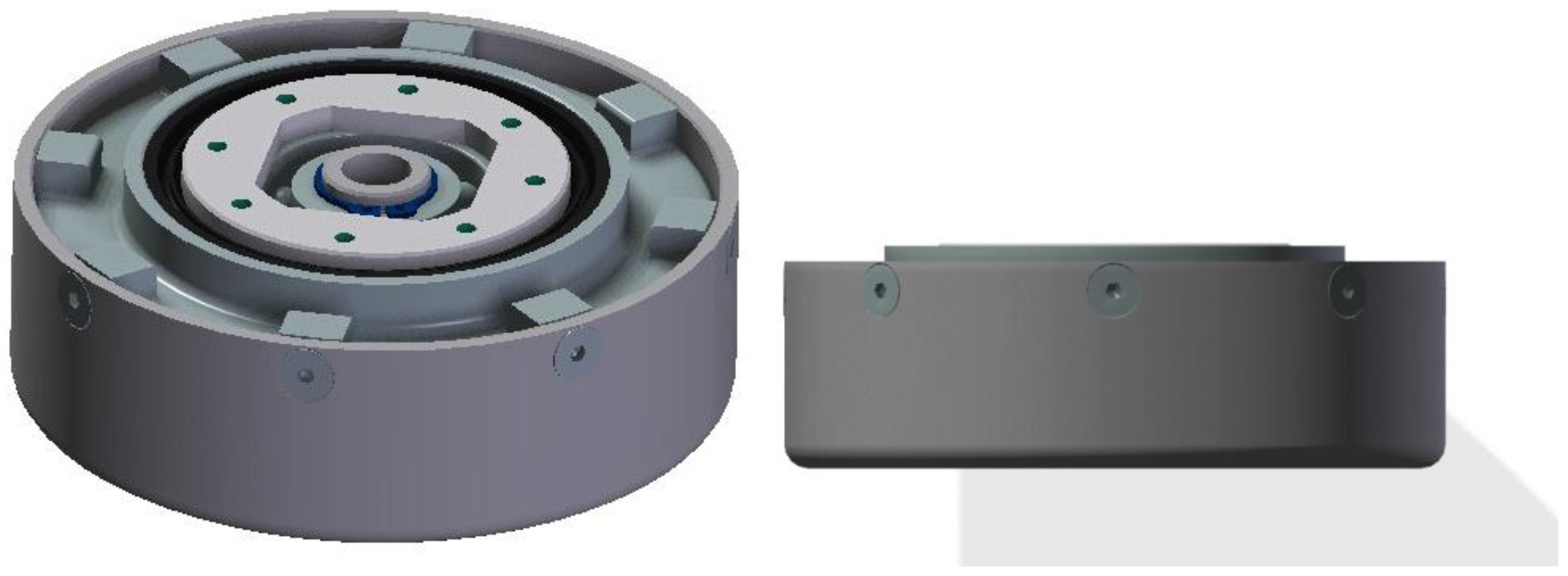
The system has been designed in order to transmit continuously 24 Nm at 2500 rpm from input to output. The expected operational temperature is between −40 °C to +70 °C. The safety factor in the transmitted torque is 1.5 in the worst case scenario. Magnets magnetization decreases with temperature, so at 70 °C the torque transmission capability will be the lowest. Therefore, the design point should be 36 Nm when operating at +70 °C. The final mechanical design for the magnetic torque limiter (1:1 ratio gear) is shown in
Figure 2.
Table 1 shows the main geometrical parameters given for architectures:
The aeronautical magnetic torque limiters torque capability is 101 kNm/m3, in the same order as conventional commercial ones (for example, Ruflex KTR 01 2TF torque limiter from 52 to 150 kNm/m3, (“KTR catalog”, 2013)). Moreover, their maximum speeds and efficiency are larger than those mechanical based on friction. In contrast to conventional mechanical fusible or wear-based torque limiters, magnetic ones do not present a severe degradation or failure when the torque limitation is activated.
The magnetic profile of the architecture has been analyzed. With this magnetic profile, the efficiency and thermal behavior can also be studied. The efficiency is mainly determined by power losses generated by eddy currents and hysteresis cycle. Three areas of heat generation can be distinguished: magnets, housings of magnets, and external surroundings.
Figure 3 represents the magnetic field generated and the main thermal implications. There are 23 pairs of magnet with one polarization and 23 pairs of magnetic with the opposite.
Due to the magnetic yokes included in this architecture, no external field appears in the surroundings of the 1:1 torque limiter. In this case, as both inner and outer parts are synchronized, a solidary magnetic shield can be used so the magnetic effect out of the device is completely null. This device will fulfill the magnetic effect requirement of the RTCA-DO-160E.
From a thermal point of view, two states must be considered: normal operation and torque limiter function.
In the normal operation mode, no heat generation is expected because both wheels are synchronized. As they rotate together there are not any alternant magnetic fields, so no eddy current will be generated, and therefore no heat generation. The expected efficiency in this mode is larger than 99%, like in an elastic coupling.
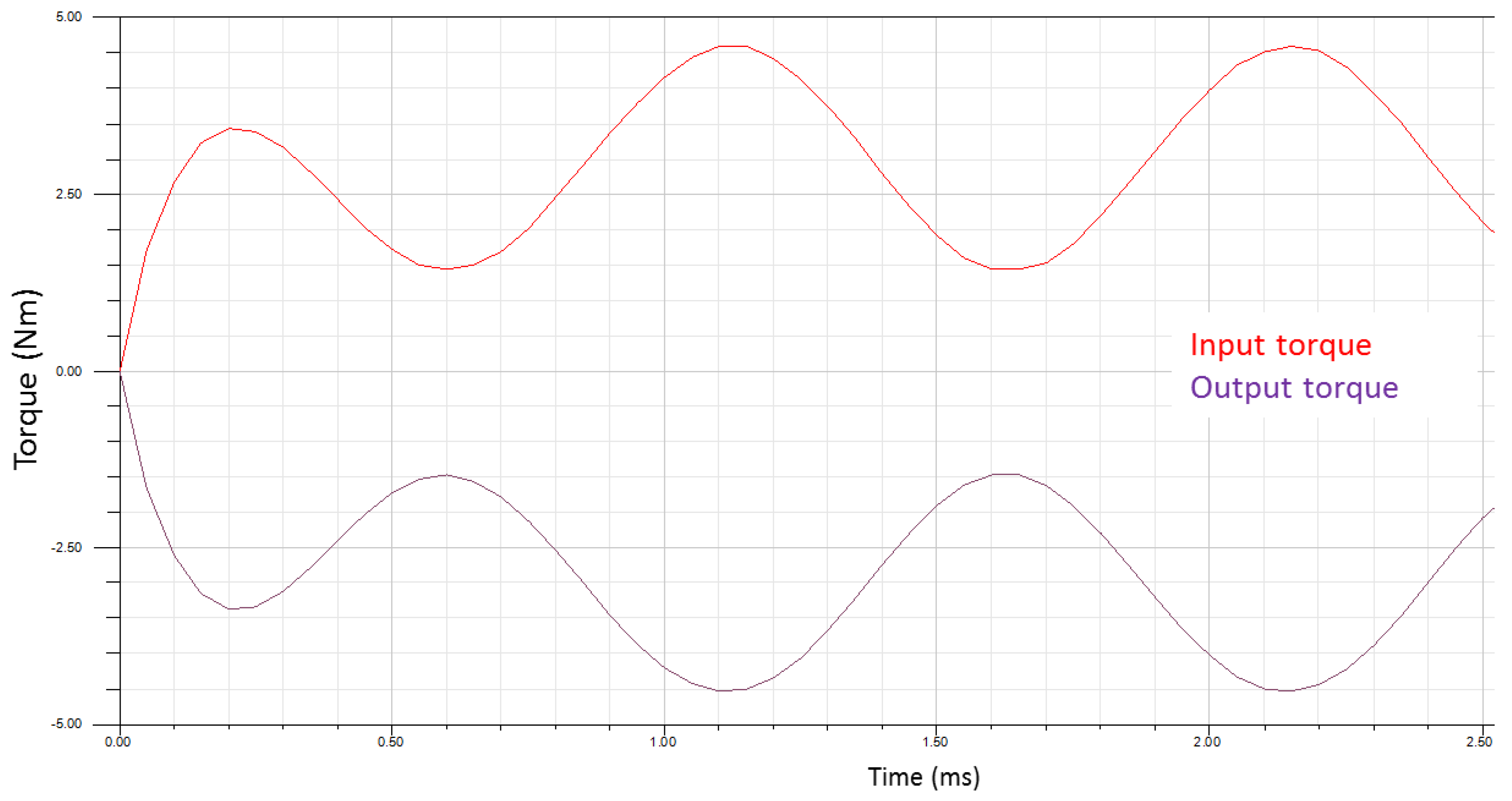
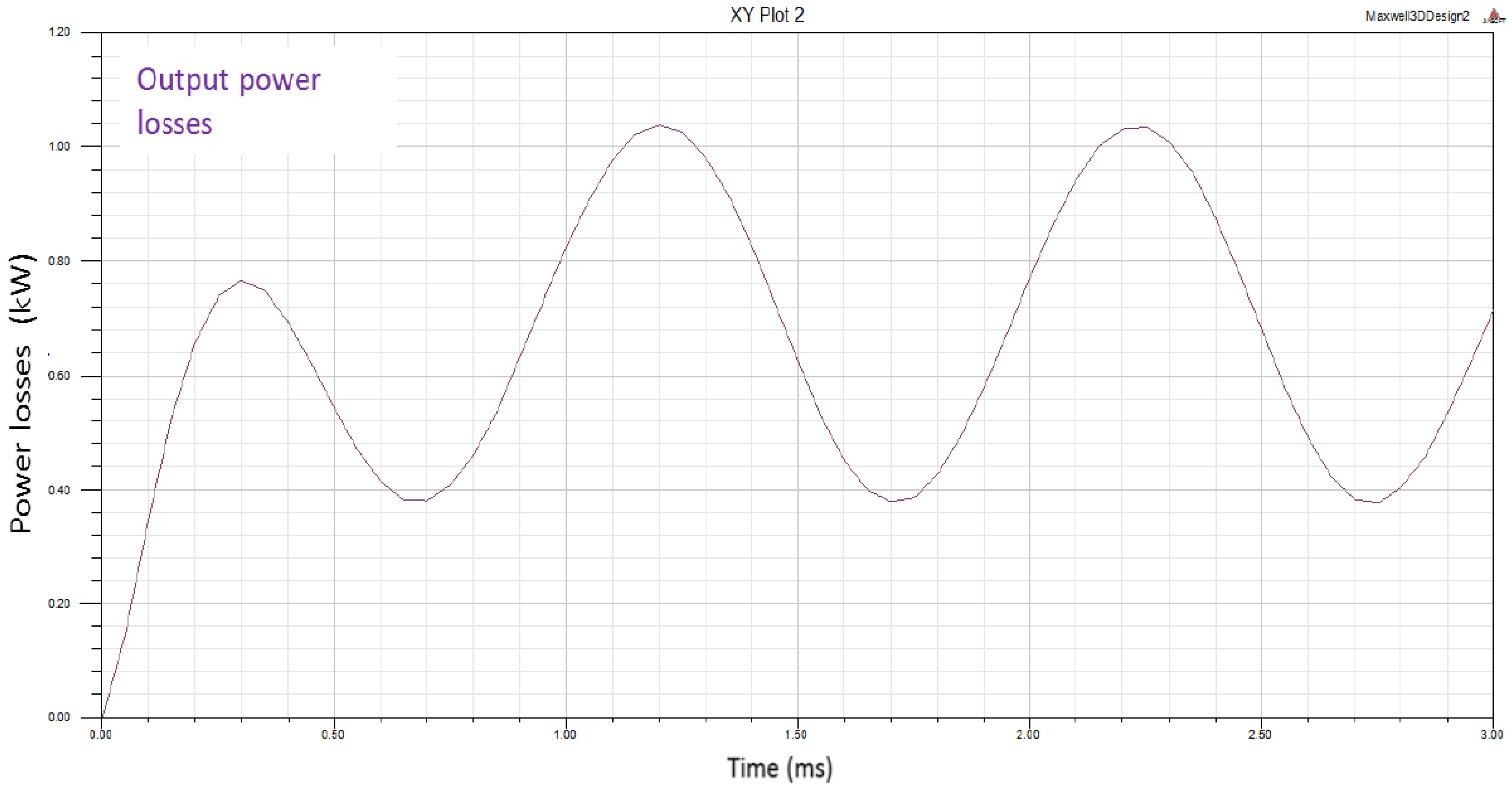
In the torque limiter mode there will be a sliding that will generate both alternant magnetic fields and eddy currents. The eddy current will generate heat as well as drag torque. The drag torque and the optimized power losses at 2250 rpm for each area have been calculated and are represented in the
Figure 4 and
Figure 5.
In this operation mode (torque limiter mode), the system transmits two different torques: one due to the magnetic iteration between magnets, and one due to the electromagnetic iteration between magnets and eddy current generated in the inner frame element (made in stainless steel). The magnet–magnet torque has a total component which is practically zero because the maximum attraction is equal to the maximum repulsion. However, a drag torque appears between the moving magnets and the eddy current generated by the sliding. This drag torque depends proportionally to the sliding speed and to the conductivity of the locked element.
The expected drag torque while sliding (torque limiter function) is on average 3.25 Nm for a relative speed difference of 2250 rpm. This drag torque contributes to the reengaging of the limiter if the overload is released.
The expected heat generation in the whole system due to eddy currents is 700 watts. This amount of energy has to be dissipated in order to prevent permanent damage on the magnets. The selected magnet material has a critical temperature of 250 °C—much above the maximum expected temperature in the worst case—so thermally, the 1:1 coupling is correct. Such a high safety margin in temperatures could lead to a more optimized device using materials with lower critical temperature but higher magnetic properties, which would imply lower weight and volume. The magnetic confinement allows selecting any kind of material for the surroundings.
3. Manufacturing and Assembly
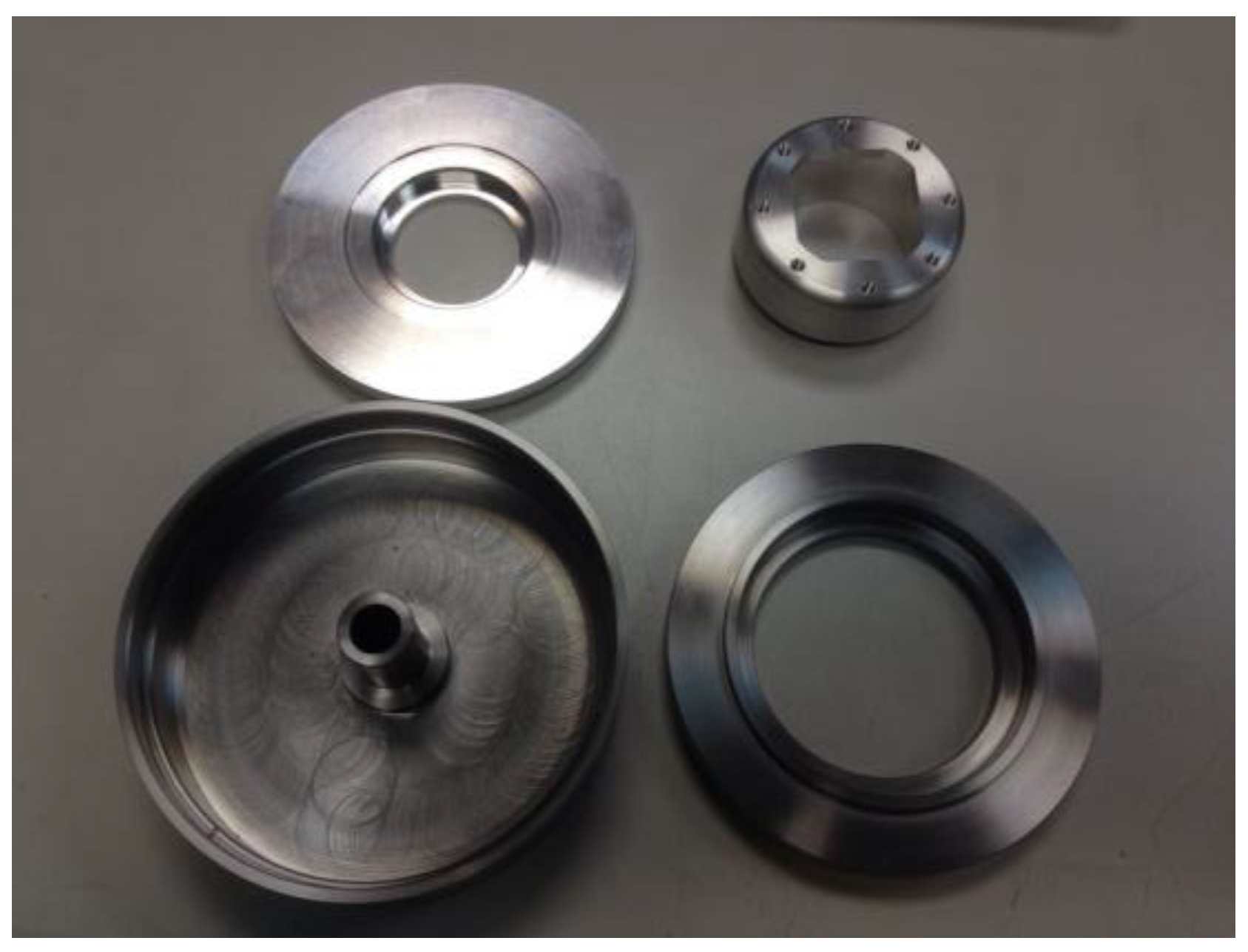
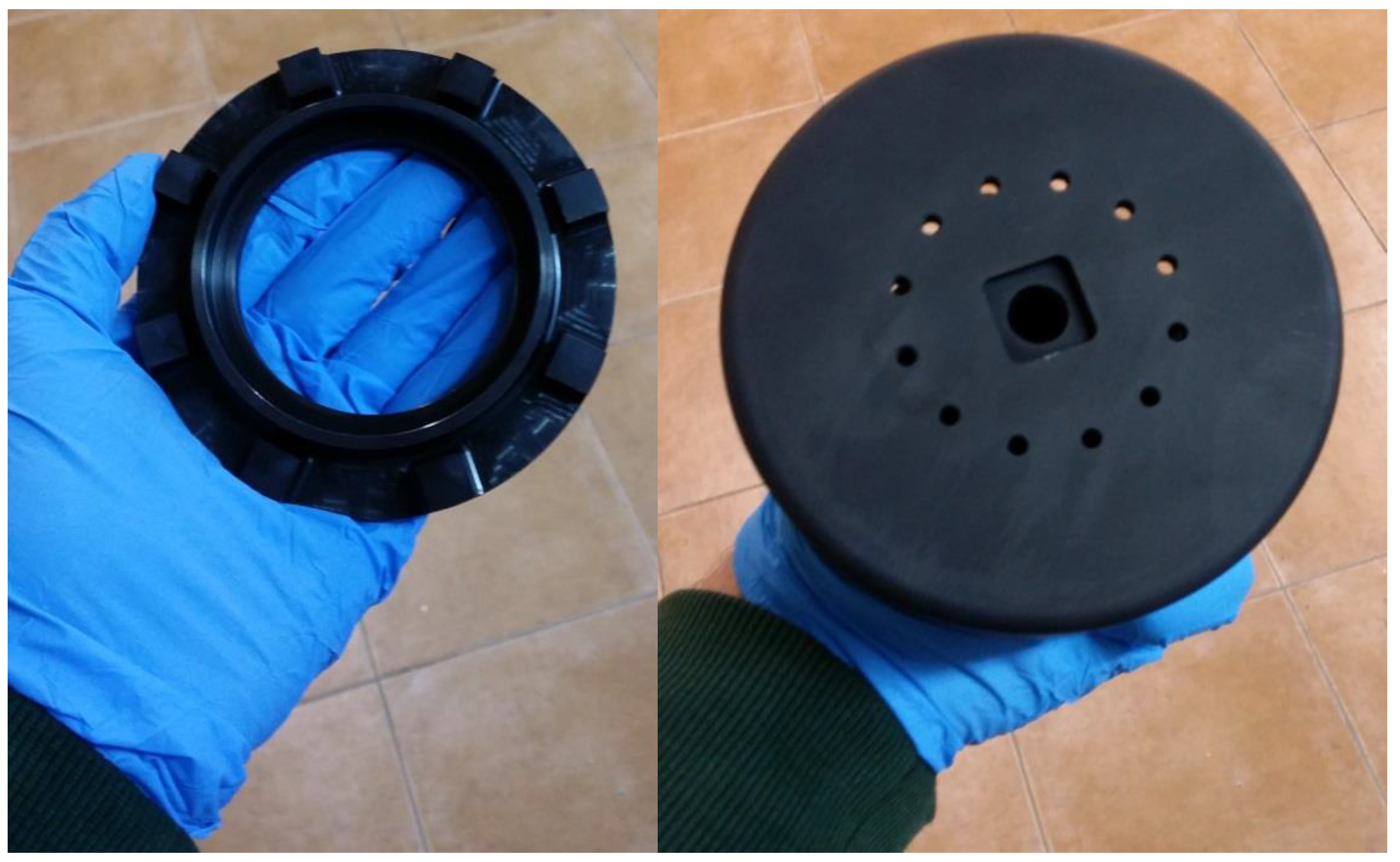
The parts were made with different materials like aluminum alloys, ferromagnetic steel, and permanent magnetic materials. The external (input) and internal parts (output) are shown in
Figure 6.
The parts fits and tolerances were checked after manufacturing to guarantee the correct assembly, reducing the clearances between parts to prevent vibrations and wear as it appears in
Figure 7.
As there are parts made of ferromagnetic steel susceptible of oxidation and corrosion, an antioxidation coating was applied to all these parts,
Figure 8.
The assembly of the magnets was done using special adhesive and tools. A protection of the magnets was used in order to prevent jamming caused by chips or small chunks from the magnets.
The input and output has been designed to be mechanically joined by a bearing that allows relative rotation in case of sliding. The original bearing grease was removed and replaced by a special aerospace grease (ROCOL AEROSPEC 200 XG287) suitable for low temperature applications.
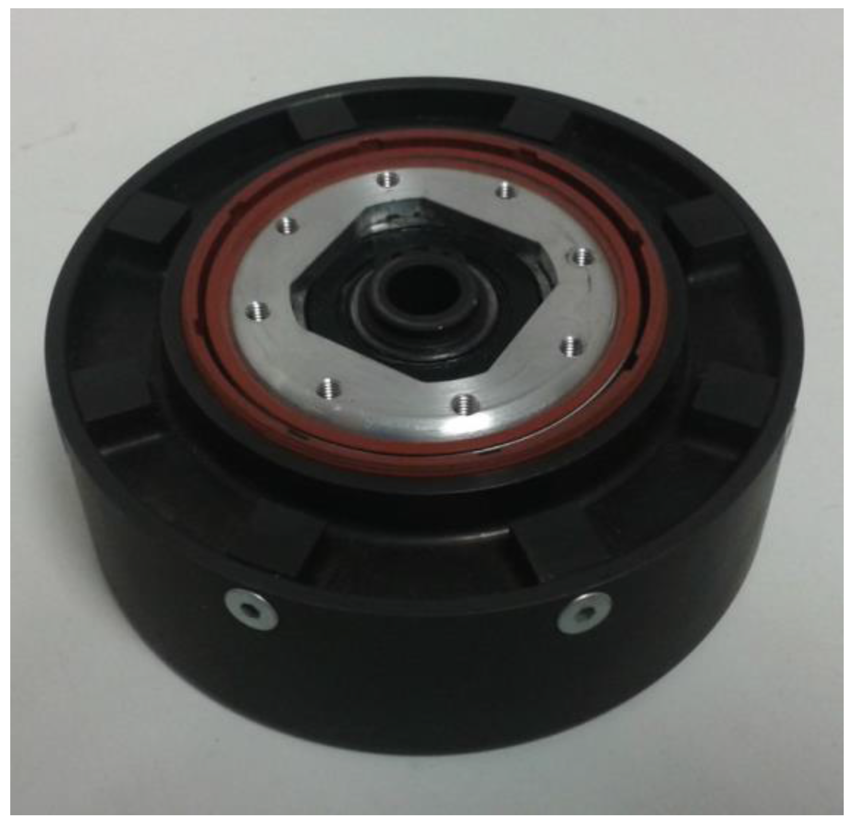
Finally, all the parts were screwed and the screws were locked using a thread locking adhesive. The sealing between the rotatory parts was inserted. The final torque limiter, assembled and treated, is shown in
Figure 9.
4. Tests
The tests for the torque limiter were done in order to obtain a characterization of physical and functional performances following the RTCA DO-160E standard. According to the work plan the torque limiter was both manufactured and assembled. Then, the prototype was installed inside the thermal chamber in the test bench.
The torque limiter was installed in the functional test rig. The test rig is composed of an AC motor, a brake, a clutch, and a sensing system. The final version of the torque limiter sensing system has a set of sensors listed below:
one torque/speed/angle sensor in the input axle and one in the output axle.
two temperature sensors distributed closed to both axles and plates and one pyrometer to determine the temperature in the torque limiter.
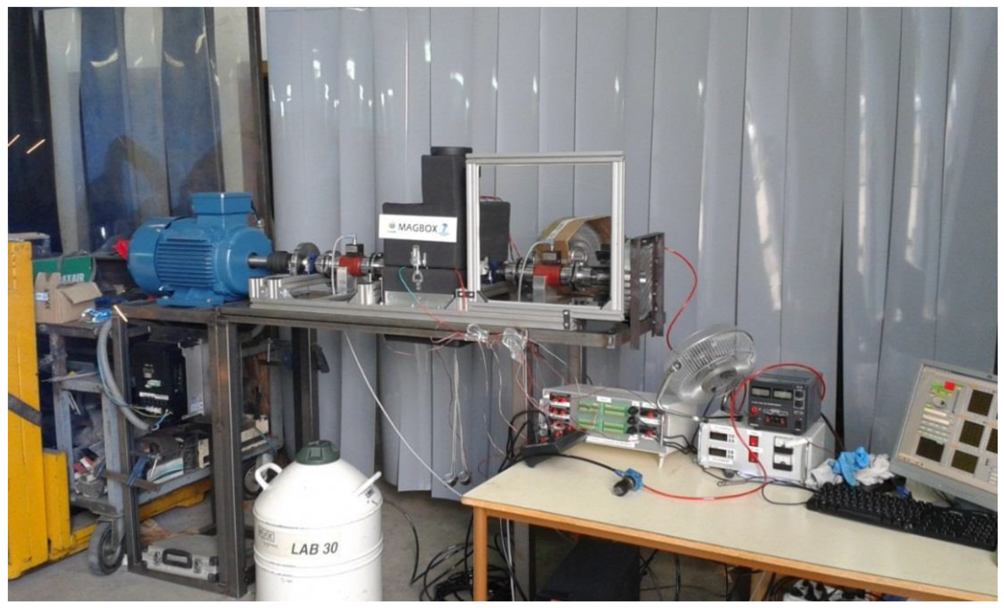
The motor, clutch, and brake are controlled by analogic electronic system. The sensor measurement is given by a conditioning electronics and registered into different programs developed for this purpose,
Figure 10. At this point testing of the torque limiter at the different temperatures started,
Figure 11.
4.1. Quasistatic Tests
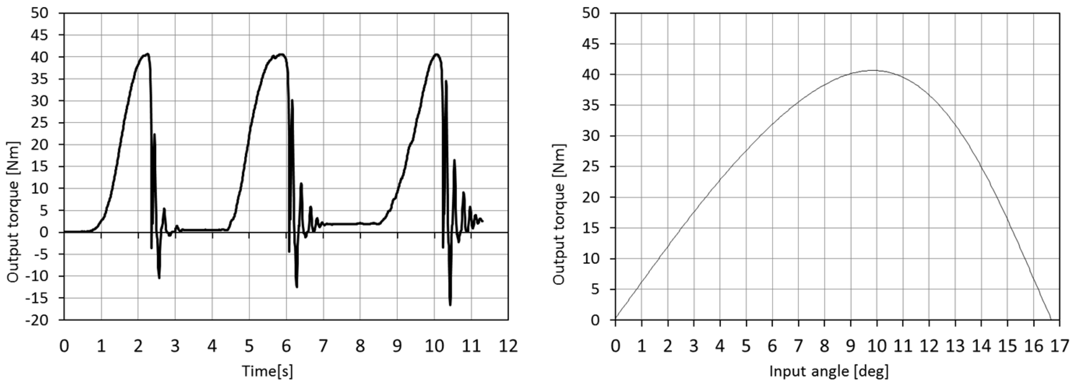
In order to determine sliding torque or maximum transmittable torque, torsional stiffness (elasticity) and torque ripple of the output in the torque limiter was blocked and the input rotated manually at very low speed. The torque ripple and the torsional stiffness are shown in
Figure 12. These tests have been done at the minimum and maximum operational temperatures (−40 °C, +20 °C, and +70 °C) according to the DO-160E. Additionally, these tests have been done at the “short time extremes operational temperatures” of −55 °C and +90 °C.
The sliding torque at 20 °C temperature was rated at 40.5 Nm. The torsional stiffness calculated is 4.1 Nm/°. The variation of the sliding torque in respect to the temperature is shown in
Figure 13. As expected, the lower the temperature is the higher the sliding torque. The variation of the maximum torque is around +12% in the lowest temperature tested and −12% in the highest temperature with an almost linear variation with temperature.
When the system is forced to put one magnet face-to-face against the other (10°) the transmittable torque is maximum. From 10° to 16.5° the system is able to push forward the output element. Beyond 16.5°, the system is able to push but with smaller torque. If we continue to rotate input element while output is locked, the system will reach a situation in which the input will be braked by the output (negative torques). If we continue to rotate input, the system will again overpass the maximum transmittable torque and the input element will reach the next stable equilibrium position. Before the maximum torque, the equilibrium position of the element is reached at 0° of relative rotation, however, once the system overpasses the maximum torque, the system is forced to rotate forward until the next equilibrium position, which will be reached at approximately 32° away from the previous one.
The torsional stiffness follows a similar behavior. The torque ripple has been measured using several elastic couplings between the sensors and torque limiter therefore the time for the damping is not completely due to the torque limiter.
4.2. Performance Tests
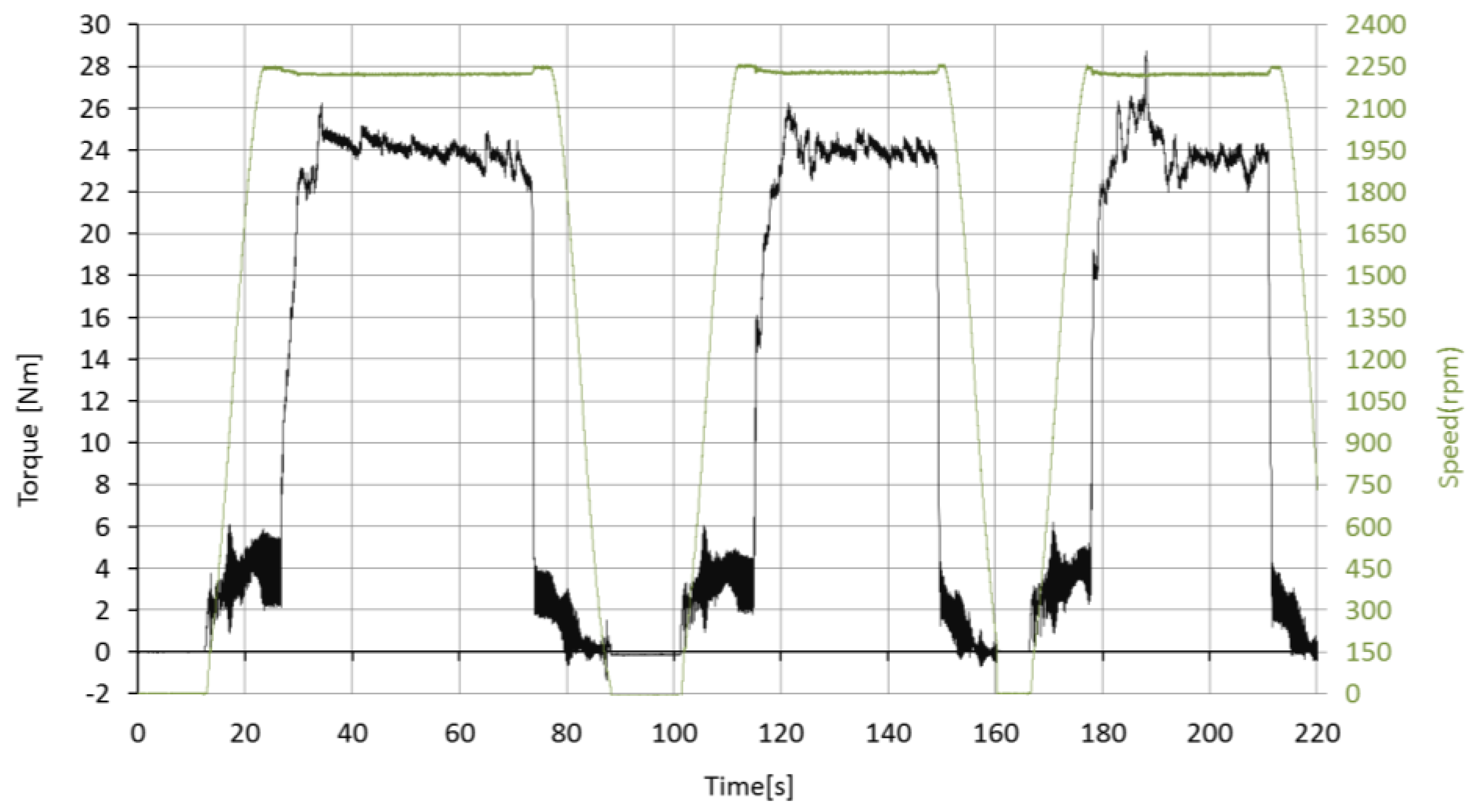
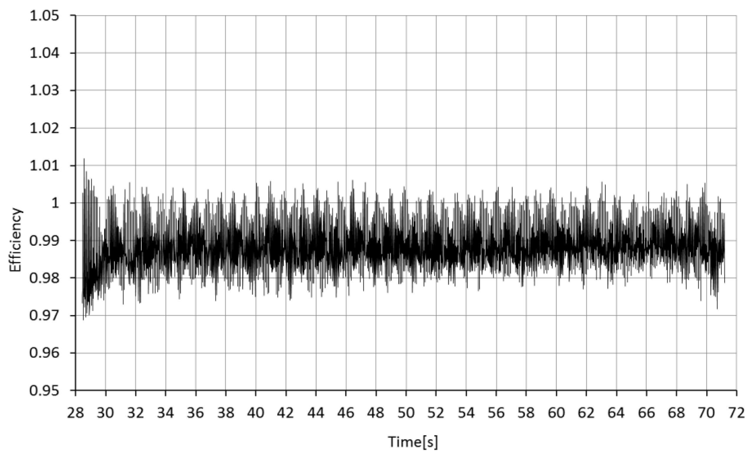
When the motor was activated, the speed reached 2250 rpm without load. Then, the brake loaded the torque limiter output until reaching 24 Nm. At this nominal condition the torque limiter was loaded during 45 s. This cycle was repeated 3 times in a row. The test cycles (speed and torque) and the efficiency in the torque transmission are shown in
Figure 14 and
Figure 15.
The efficiency was rated in 99.2%. This efficiency includes the efficiency of 4 ball bearings at room temperature (2 per sensor) and 1 ball bearing close to the thermal chamber. It also includes the efficiency of two elastic couplings.
The performance tests were carried out successfully, transmitting correctly the nominal 24 Nm at the nominal speed for each of the temperature cases.
The global efficiency has always been measured above 98.5% including the efficiency of 4 ball bearings at room temperature (2 per sensor) and 1 ball bearing close to the thermal chamber. No heating has been tracked in the torque limiter while operating.
4.3. Endurance Tests
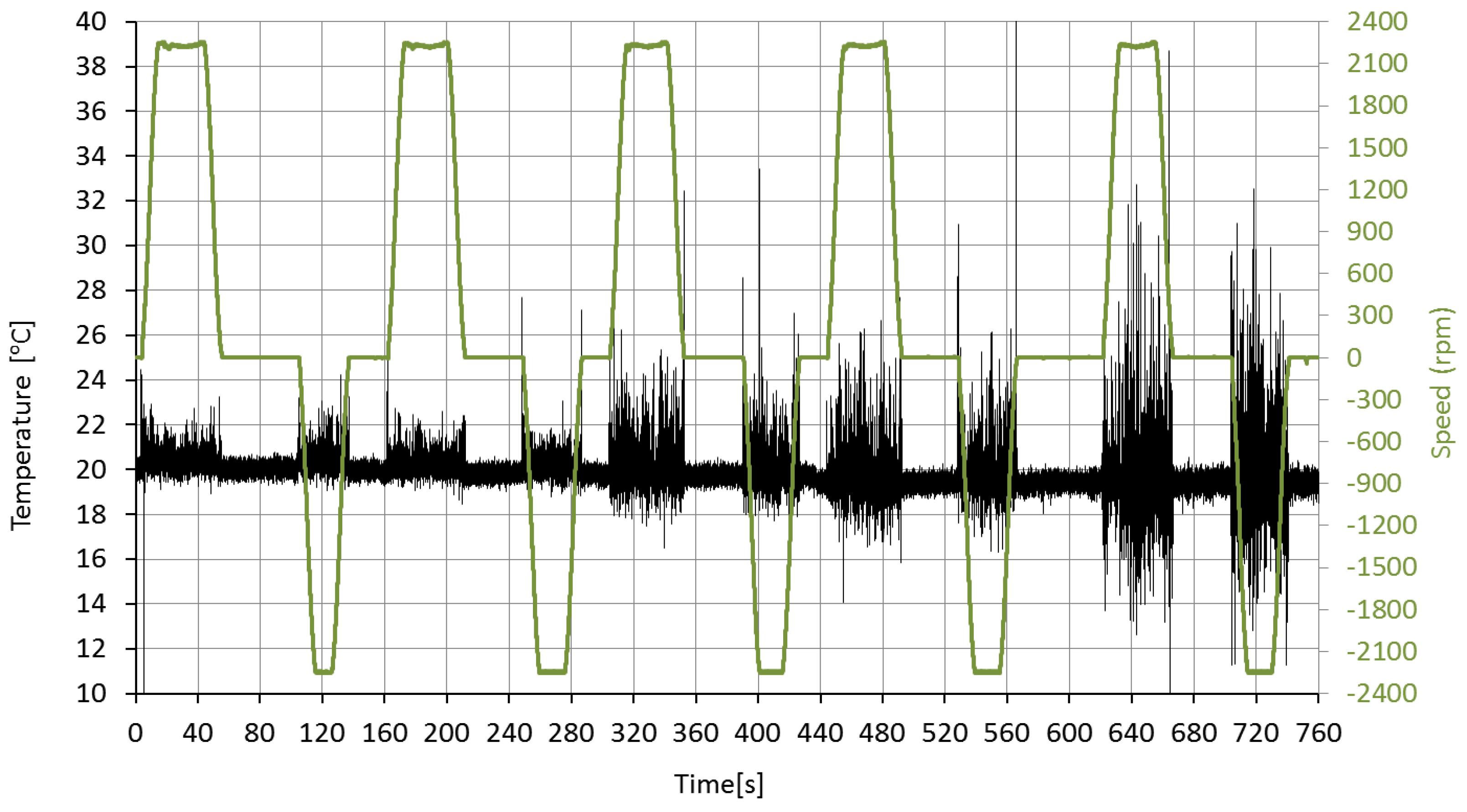
The objective is to simulate an aborted Landing/Go around operation cycle (most critical case) at different operational temperatures for the torque limiter. The function, efficiency, and accuracy in the mechanical power and angle transmission have been evaluated from the data presented in
Figure 16.
The endurance tests have been done simulating 50 operational cycle without degradation of the torque limiter and without the need of maintenance.
4.4. Overload Tests
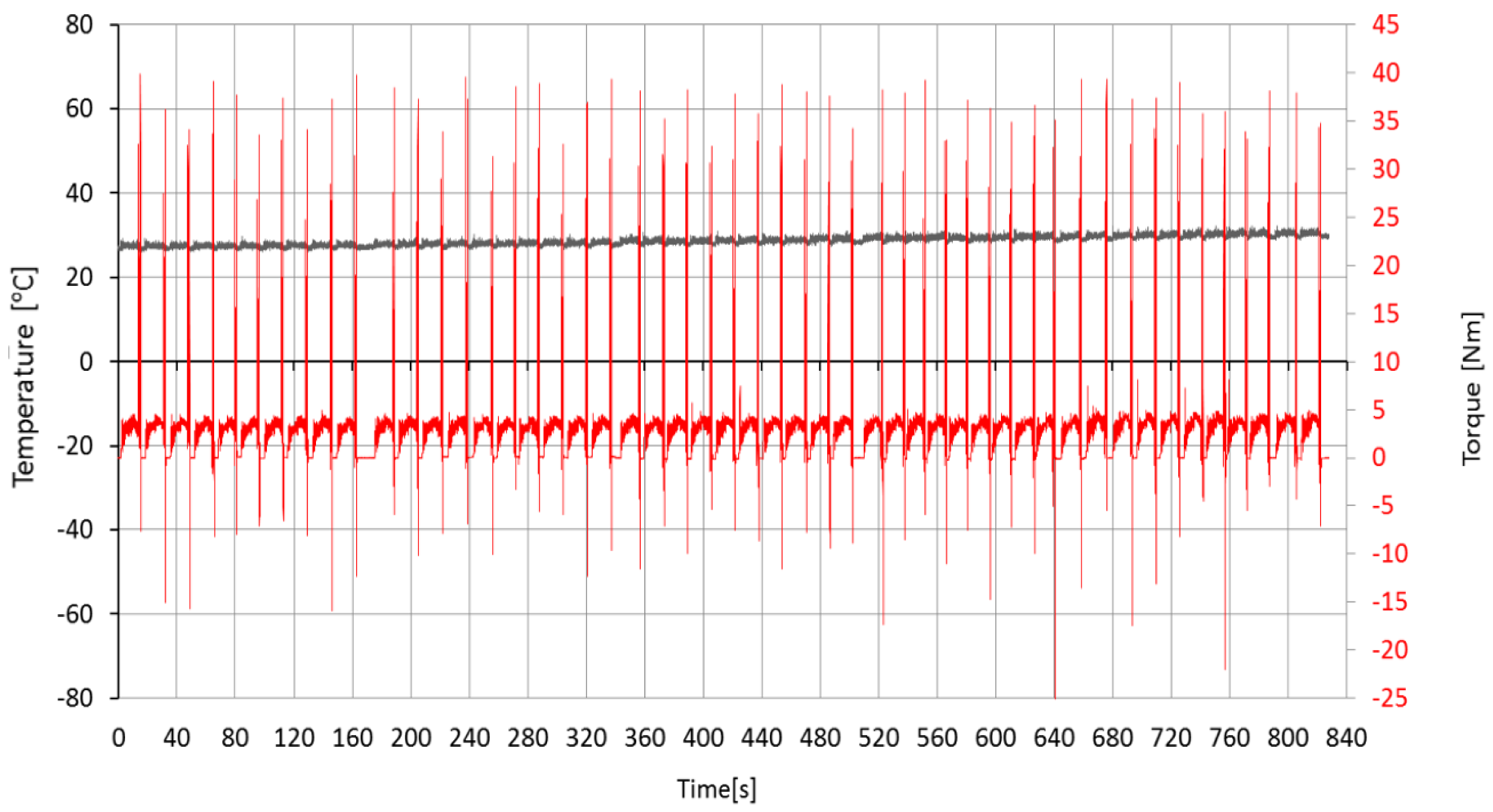
The objective of this test is demonstrate the torque limiter function. The test bench motor was activated according to a certain output rate. Simultaneously, the brake was loaded according to the load cycle, and then suddenly the brake overloaded making the torque limiter to “jump”.
Figure 17 demonstrates 50 consecutive jammings showing the output torque (sensor between brake and torque limiter).
This kind of test has been repeated during 200 jamming or overloads without significant degradation of the system afterward.
5. Conclusions
The magnetic torque limiter developed for aeronautical applications has demonstrated full compliance with the RTCA-DO-160E. It is able to operate in a wide temperature range (−50 °C to +90 °C). Moreover, overload protection has been demonstrated for more than 200 jamming events without damage or maintenance in the device.
This work demonstrates that magnetic torque limiters are a step forward in these kinds of mechanism elements, giving additional advantages with respect to conventional ones without increasing significantly the weight of the device.


 ,
, 


