Heat Treatments and Critical Quenching Rates in Additively Manufactured Al–Si–Mg Alloys

 , ,
, ,
Abstract
:1. Introduction
2. Methodology
2.1. LPBF Samples
2.2. Cast Samples
2.3. Sample Nomenclature
2.4. Spark Emission Spectroscopy
2.5. Heat Treatment
2.6. Hardness Evaluation
2.7. Micro Sections
2.8. Porosity Measurements
2.9. Atom Probe Tomography
3. Results
3.1. Chemical Compositions
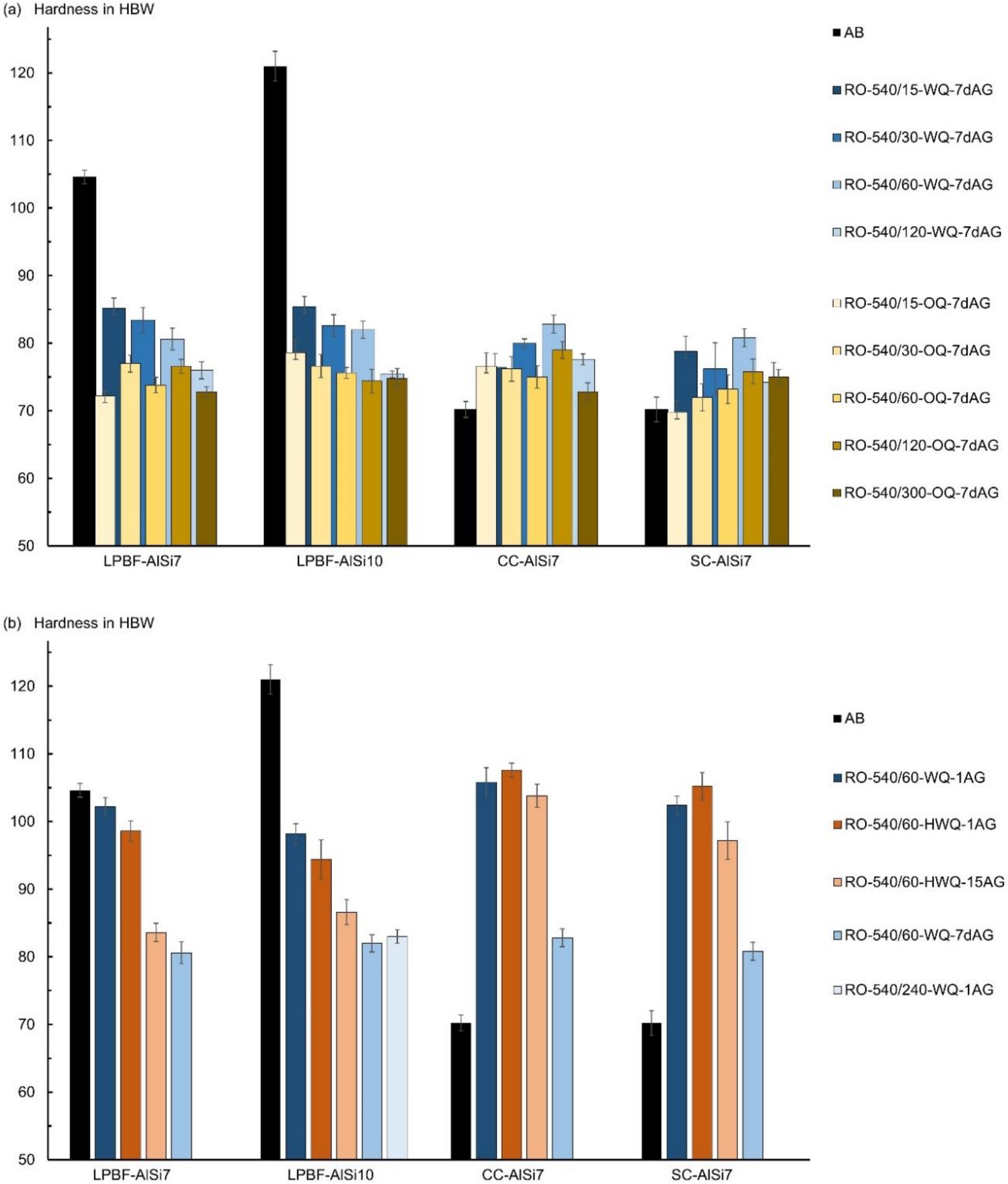
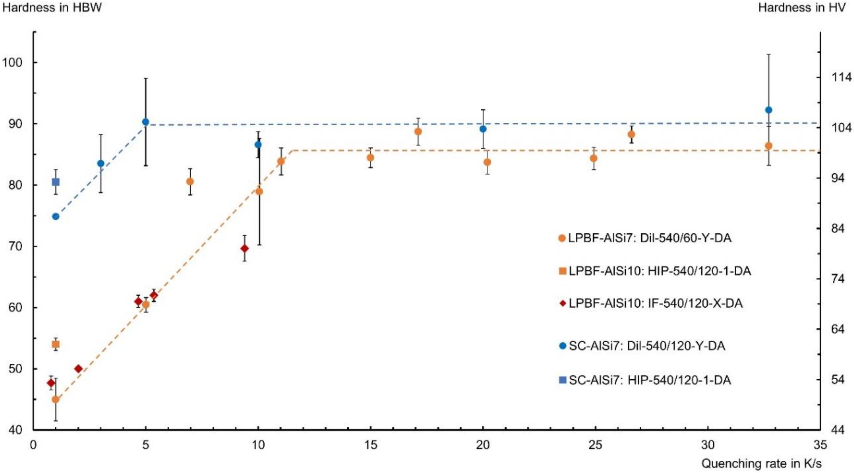
3.2. Hardness
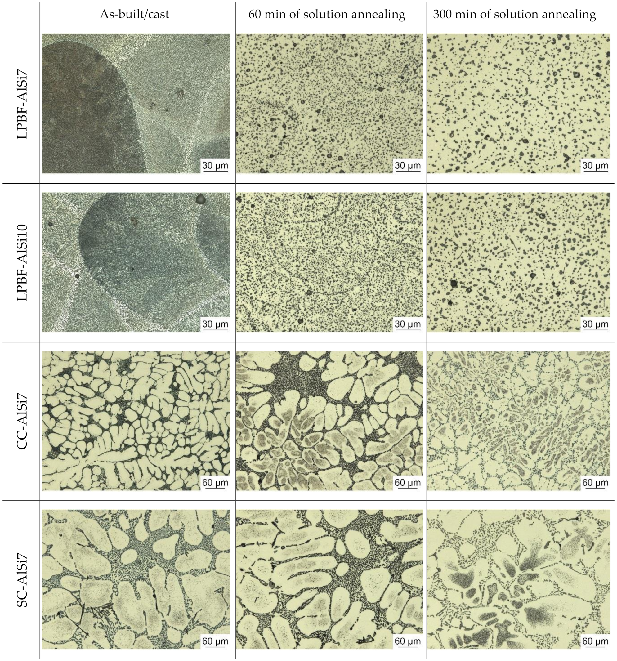
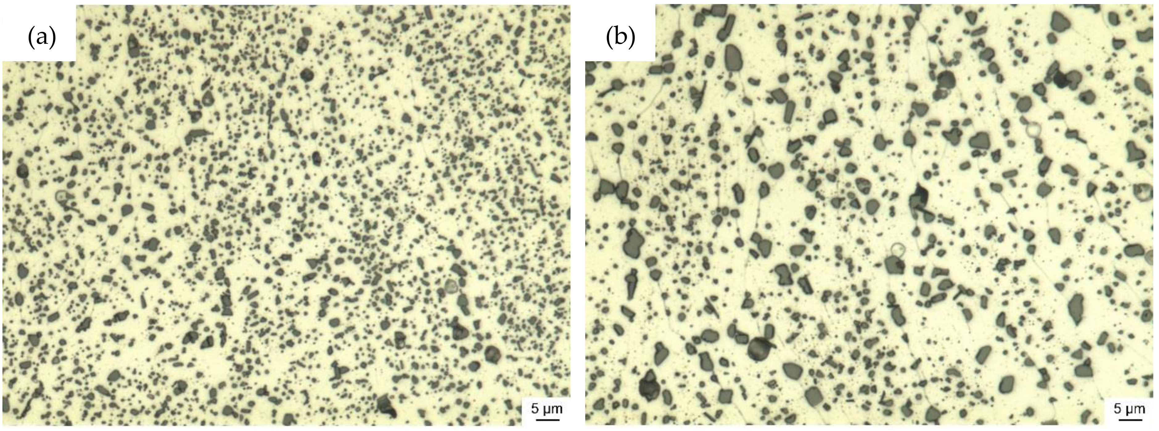
3.3. Micro Sections
3.4. Porosity
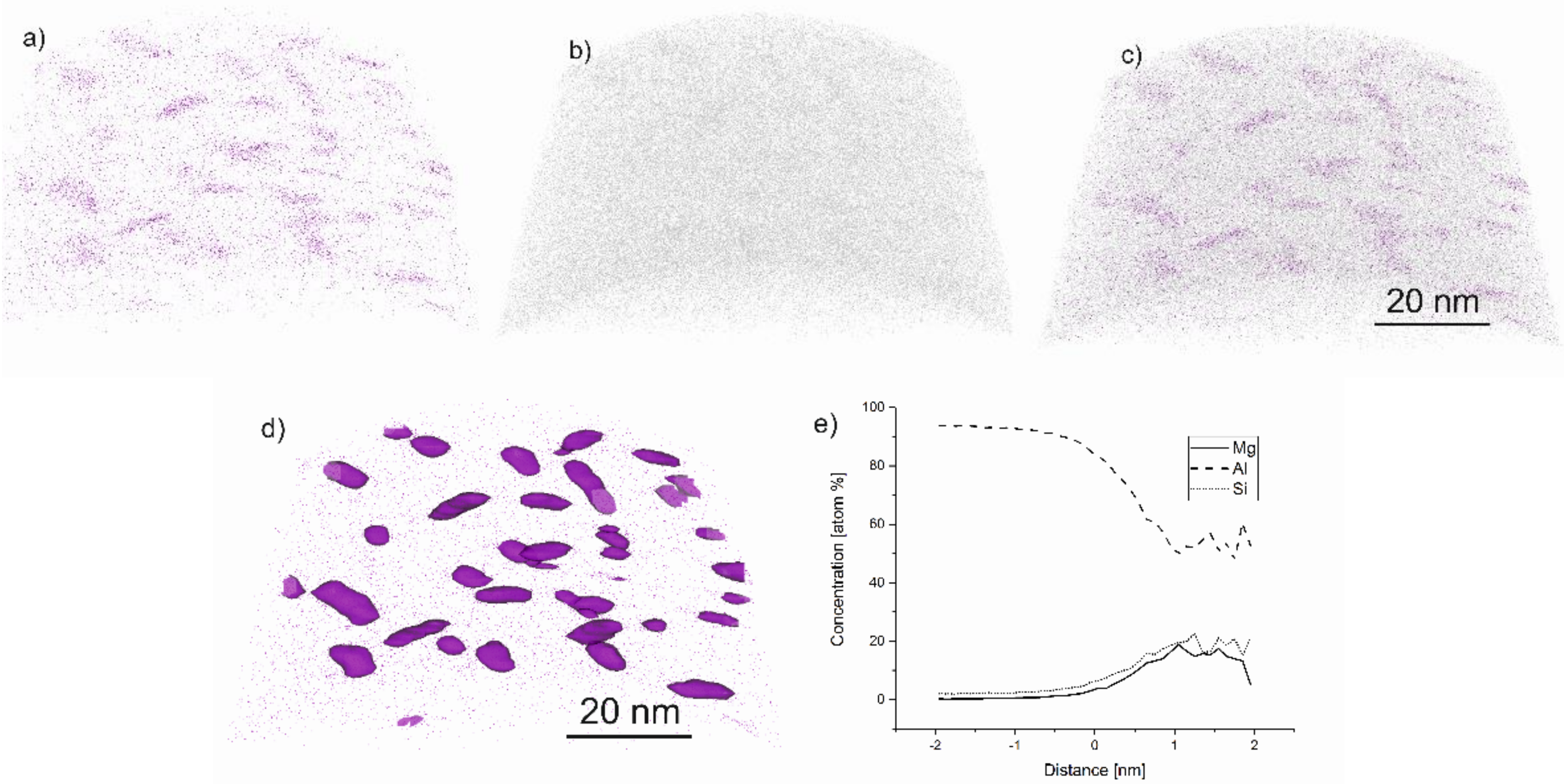
3.5. Atom Probe Tomography
4. Discussion
5. Conclusions
Author Contributions
Funding
Acknowledgments
Conflicts of Interest
References
- Hitzler, L.; Merkel, M.; Hall, W.; Öchsner, A. A review of metal fabricated with laser- and powder-bed based additive manufacturing techniques: Process, nomenclature, materials, achievable properties, and its utilization in the medical sector. Adv. Eng. Mater. 2018, 20, 1700658. [Google Scholar] [CrossRef] [Green Version]
- DebRoy, T.; Wei, H.L.; Zuback, J.S.; Mukherjee, T.; Elmer, J.W.; Milewski, J.O.; Beese, A.M.; Wilson-Heid, A.; De, A.; Zhang, W. Additive manufacturing of metallic components – process, structure and properties. Prog. Mater. Sci. 2018, 92, 112–224. [Google Scholar] [CrossRef]
- Aboulkhair, N.T.; Simonelli, M.; Parry, L.; Ashcroft, I.; Tuck, C.; Hague, R. 3D printing of Aluminium alloys: Additive Manufacturing of Aluminium alloys using selective laser melting. Prog. Mater. Sci. 2019, 106, 100578. [Google Scholar] [CrossRef]
- Prashanth, K.G.; Scudino, S.; Klauss, H.J.; Surreddi, K.B.; Löber, L.; Wang, Z.; Chaubey, A.K.; Kühn, U.; Eckert, J. Microstructure and mechanical properties of Al–12Si produced by selective laser melting: Effect of heat treatment. Mater. Sci. Eng. A 2014, 590, 153–160. [Google Scholar] [CrossRef]
- Hitzler, L.; Hirsch, J.; Heine, B.; Merkel, M.; Hall, W.; Öchsner, A. On the anisotropic mechanical properties of selective laser melted stainless steel. Materials 2017, 10, 1136. [Google Scholar] [CrossRef] [Green Version]
- Hitzler, L.; Hirsch, J.; Tomas, J.; Merkel, M.; Hall, W.; Öchsner, A. In-plane anisotropy of selective laser melted stainless steel: The importance of the rotation angle increment and the limitation window. Proc. Inst. Mech. Eng. Part L 2019, 233, 1419–1428. [Google Scholar] [CrossRef]
- Prashanth, K.G.; Eckert, J. Formation of metastable cellular microstructures in selective laser melted alloys. J. Alloys Compd. 2017, 707, 27–34. [Google Scholar] [CrossRef]
- Hitzler, L.; Janousch, C.; Schanz, J.; Merkel, M.; Heine, B.; Mack, F.; Hall, W.; Öchsner, A. Direction and location dependency of selective laser melted AlSi10Mg specimens. J. Mater. Process. Technol. 2017, 243, 48–61. [Google Scholar] [CrossRef]
- Hitzler, L.; Schoch, N.; Heine, B.; Merkel, M.; Hall, W.; Öchsner, A. Compressive behaviour of additively manufactured AlSi10Mg. Mat. Wiss. Werkstofftech. 2018, 49, 683–688. [Google Scholar] [CrossRef]
- Hitzler, L.; Hirsch, J.; Schanz, J.; Heine, B.; Merkel, M.; Hall, W.; Öchsner, A. Fracture toughness of selective laser melted AlSi10Mg. Proc. Inst. Mech. Eng. Part L 2019, 233, 615–621. [Google Scholar] [CrossRef]
- Hitzler, L.; Sert, E.; Schuch, E.; Öchsner, A.; Merkel, M.; Heine, B.; Werner, E. Fracture toughness of L-PBF fabricated aluminium-silicon: A quantitative study on the role of crack growth direction with respect to layering. Prog. Addit. Manuf. submitted. 2020. [Google Scholar]
- Aboulkhair, N.T.; Maskery, I.; Tuck, C.; Ashcroft, I.; Everitt, N.M. The microstructure and mechanical properties of selectively laser melted AlSi10Mg: The effect of a conventional t6-like heat treatment. Mater. Sci. Eng. A 2016, 667, 139–146. [Google Scholar] [CrossRef]
- Hitzler, L.; Sert, E.; Merkel, M.; Öchsner, A.; Werner, E. Fracture toughness and fatigue strength of selective laser melted aluminium-silicon: An overview. In TMS 2019 148th Annual Meeting & Exhibition Supplemental Proceedings; Springer: Cham, Switzerland, 2019; pp. 407–412. [Google Scholar]
- Tang, M.; Pistorius, P.C. Oxides, porosity and fatigue performance of AlSi10Mg parts produced by selective laser melting. Int. J. Fatigue 2017, 94, 192–201. [Google Scholar] [CrossRef]
- De Geuser, F.; Lefebvre, W.; Blavette, D. 3D atom probe study of solute atoms clustering during natural ageing and pre-ageing of an Al-Mg-Si alloy. Philos. Mag. Lett. 2006, 86, 227–234. [Google Scholar] [CrossRef] [Green Version]
- Serizawa, A.; Hirosawa, S.; Sato, T. Three-dimensional atom probe characterization of nanoclusters responsible for multistep aging behavior of an Al-Mg-Si alloy. Metall. Mater. Trans. A 2008, 39, 243–251. [Google Scholar] [CrossRef]
- Murali, S.; Arunkumar, Y.; Chetty, P.V.J.; Raman, K.S.; Murthy, K.S.S. The effect of preaging on the delayed aging of Al−7Si−0.3Mg. JOM 1997, 49, 29–33. [Google Scholar] [CrossRef]
- Hafenstein, S.; Werner, E. Simultaneous hot isostatic pressing and solution annealing of aluminium cast alloys followed by instantaneous aging at elevated temperatures. IOP Conference Series: Materials Science and Engineering 2018, 416, 012084. [Google Scholar] [CrossRef]
- Hafenstein, S.; Werner, E. Direct aging of a hot isostatically pressed A356 aluminum cast alloy. Mater. Sci. Eng. A 2019, 768. [Google Scholar] [CrossRef]
- Hafenstein, S.; Werner, E. Pressure dependence of age-hardenability of aluminum cast alloys and coarsening of precipitates during hot isostatic pressing. Mater. Sci. Eng. A 2019, 757, 62–69. [Google Scholar] [CrossRef]
- Buchbinder, D.; Meiners, W.; Wissenbach, K.; Poprawe, R. Selective laser melting of aluminum die-cast alloy—correlations between process parameters, solidification conditions, and resulting mechanical properties. J. Laser Appl. 2015, 27, S29205. [Google Scholar] [CrossRef]
- Sha, G.; Möller, H.; Stumpf, W.E.; Xia, J.H.; Govender, G.; Ringer, S.P. Solute nanostructures and their strengthening effects in Al–7Si–0.6Mg alloy F357. Acta Mater. 2012, 60, 692–701. [Google Scholar] [CrossRef] [Green Version]
- Sert, E.; Hitzler, L.; Heine, B.; Merkel, M.; Werner, E.; Öchsner, A. Influence of heat treatments on the microstructure and hardness of additive manufactured AlSi10Mg samples. Pract. Metallogr. 2019, 56, 91–105. [Google Scholar] [CrossRef]
- Aboulkhair, N.T.; Tuck, C.; Ashcroft, I.; Maskery, I.; Everitt, N.M. On the precipitation hardening of selective laser melted AlSi10Mg. Metall. Mater. Trans. A 2015, 46, 3337–3341. [Google Scholar] [CrossRef]
- Tang, M. Inclusions, Porosity, and Fatigue of AlSi10Mg Parts Produced by Selective Laser Melting. Ph.D. Thesis, Carnegie Mellon University, Pittsburgh, PA, USA, 1 April 2017. [Google Scholar]
- Aboulkhair, N.T. Additive Manufacture of an Aluminium Alloy: Processing, Microstructure, and Mechanical Properties. Ph.D. Thesis, University of Nottingham, Nottingham, UK, 29 July 2016. [Google Scholar]
- Hitzler, L.; Charles, A.; Öchsner, A. The influence of post-heat-treatments on the tensile strength and surface hardness of selective laser melted AlSi10Mg. Defect Diffus. Forum 2016, 370, 171–176. [Google Scholar] [CrossRef] [Green Version]
- Aboulkhair, N.T.; Maskery, I.; Tuck, C.; Ashcroft, I.; Everitt, N.M. Improving the fatigue behaviour of a selectively laser melted aluminium alloy: Influence of heat treatment and surface quality. Mater. Des. 2016, 104, 174–182. [Google Scholar] [CrossRef]
- Brandl, E.; Heckenberger, U.; Holzinger, V.; Buchbinder, D. Additive manufactured AlSi10Mg samples using selective laser melting (SLM): Microstructure, high cycle fatigue, and fracture behavior. Mater. Des. 2012, 34, 159–169. [Google Scholar] [CrossRef]
- Brummer, M. Wärmebehandelndes heißisostatisches Pressen von Aluminiumgusslegierungen. Ph.D. Thesis, Technical University Munich, Munich, Germany, 22 May 2013. [Google Scholar]
- Hafenstein, S. Heißisostatisches Pressen von Aluminiumgusslegierungen mit integrierter Wärmebehandlung; Springer: Wiesbaden, Germany, 2019. [Google Scholar]
- E140–12b: Standard Hardness conversion Tables for Metals Relationship Among Brinell Hardness, Vickers Hardness, Rockwell Hardness, Superficial Hardness, Knoop Hardness and Scleroscope Hardness; ASTM International: West Conshohocken, PA, USA, 2007.
- Saxey, D.W.; Cairney, J.M.; McGrouther, D.; Honma, T.; Ringer, S.P. Atom probe specimen fabrication methods using a dual fib/sem. Ultramicroscopy 2007, 107, 756–760. [Google Scholar] [CrossRef]
- Kimura, T.; Nakamoto, T.; Mizuno, M.; Araki, H. Effect of silicon content on densification, mechanical and thermal properties of al-xsi binary alloys fabricated using selective laser melting. Mater. Sci. Eng. A 2017, 682, 593–602. [Google Scholar] [CrossRef] [Green Version]
- Jägle, E.A.; Sheng, Z.; Wu, L.; Lu, L.; Risse, J.; Weisheit, A.; Raabe, D. Precipitation reactions in age-hardenable alloys during laser additive manufacturing. JOM 2016, 68, 943–949. [Google Scholar] [CrossRef] [Green Version]
- Li, X.P.; Wang, X.J.; Saunders, M.; Suvorova, A.; Zhang, L.C.; Liu, Y.J.; Fang, M.H.; Huang, Z.H.; Sercombe, T.B. A selective laser melting and solution heat treatment refined Al–12Si alloy with a controllable ultrafine eutectic microstructure and 25% tensile ductility. Acta Mater. 2015, 95, 74–82. [Google Scholar] [CrossRef]
- Hafenstein, S.; Brummer, M.; Ahlfors, M.; Werner, E. Combined hot isostatic pressing and heat treatment of aluminum A356 cast alloys. HTM J. Heat Treat. Mater. 2016, 71, 117–124. [Google Scholar] [CrossRef]
- Hafenstein, S.; Werner, E.; Wilzer, J.; Theisen, W.; Weber, S.; Sunderkötter, C.; Bachmann, M. Influence of temperature and tempering conditions on thermal conductivity of hot work tool steels for hot stamping applications. Steel Res. Int. 2015, 86, 1628–1635. [Google Scholar] [CrossRef]
- Iturrioz, A.; Gil, E.; Petite, M.M.; Garciandia, F.; Mancisidor, A.M.; San Sebastian, M. Selective laser melting of alsi10mg alloy: Influence of heat treatment condition on mechanical properties and microstructure. Weld. World 2018, 62, 885–892. [Google Scholar] [CrossRef]


| Scan Speed (mm/s) | Laser Power (W) | Hatch Distance (mm) | Scan Vector Length (mm) | Rotation Angle Increment (°) | |
|---|---|---|---|---|---|
| AlSi7Mg0.3 | |||||
| Core | 1050 | 350 | 0.17 | 10 | 67 |
| Support | 900 | 350 | — | — | — |
| AlSi10Mg0.3 | |||||
| Core | 1150 | 350 | 0.17 | 10 | 67 |
| Support | 900 | 350 | — | — | — |
| Common | |||||
| Preheating temperature set to 200 °C | |||||
| Layer thickness of 50 μm | |||||
| Argon environment | |||||
| Contour irradiation and limitation window deactivated | |||||
| Abbreviation | Apparatus | Treatment |
|---|---|---|
| AB | None | As-built condition without any additional treatment being applied |
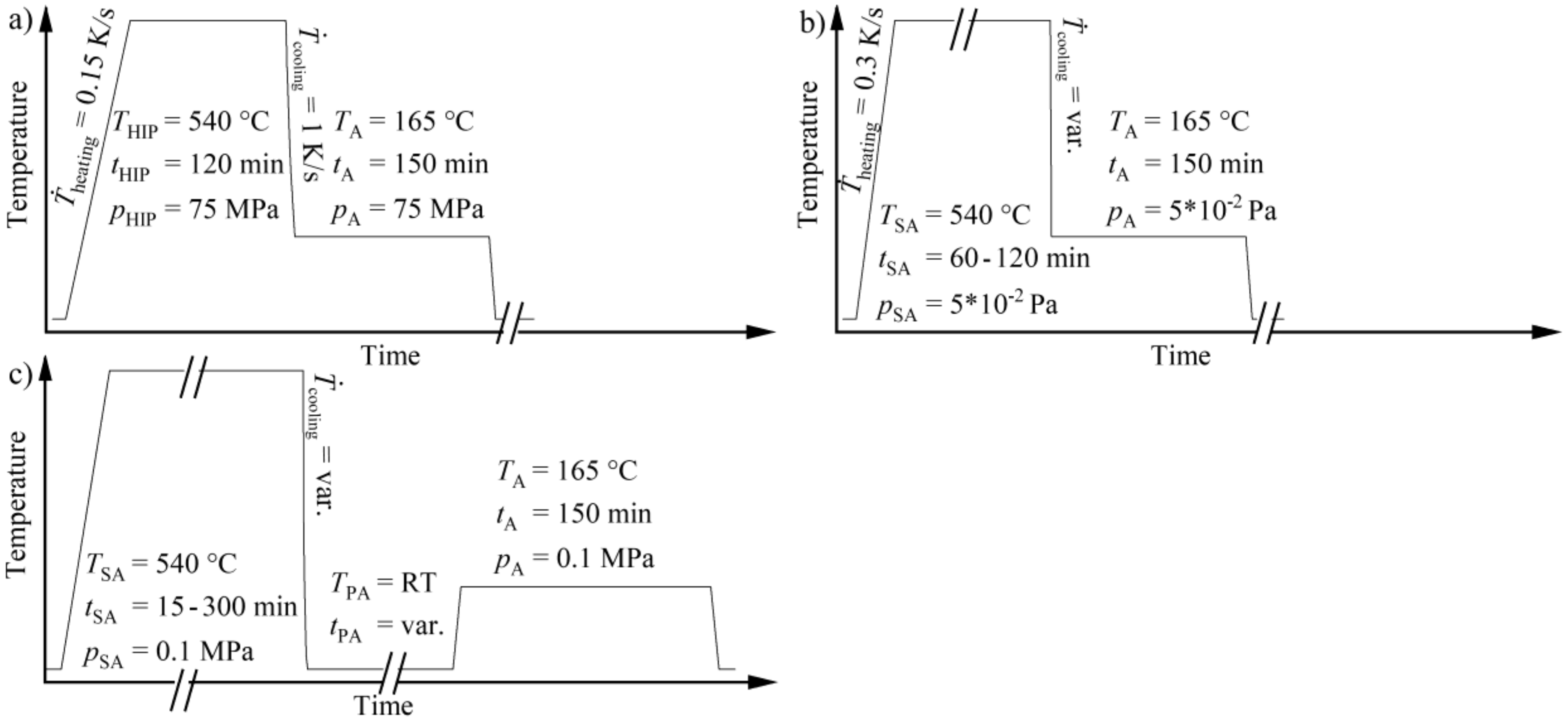
| HIP-540/120-1-DA | Hot isostatic press | Solution annealed at 540 °C for 120 min, quenched at a rate of 1 K/s to 165 °C, aged at 165 °C for 150 min; treatment performed in argon at a pressure of 75 MPa |
| Dil-540/X-Y-DA | Dilatometer | Solution annealed at 540 °C for X min, quenched at a rate of Y K/s to 165 °C, aged at 16 5 °C for 150 min; treatment performed under vacuum |
| IF-540/2-X-DA | Induction furnace | Solution annealed at 540 °C for 120 min, quenched at a rate of X K/s to 165 °C, aged at 165 °C for 150 min; treatment performed under vacuum |
| RO-540/X-Y-ZAG | Resistance furnace | Solution annealed at 540 °C for X min, quenched with Y = oil quenched (OQ; oil at 20 °C); water quenched (WQ; water at 20 °C); hot water quenched (HWQ; water at 80 °C), followed by a dwell time at room temperature of Z = 1 (1 min, immediate aging); 15 (15 min at RT); 7 d (7 days at RT), aged at 165 °C for 150 min; treatment performed in air |
| Apparatus | Sample Geometry | Quenching Rate in the Temperature Range 540 to 200 °C |
|---|---|---|
| Dilatometer | diameter of 5 mm and 8 mm in length | up to ~33 K/s |
| Resistance furnace | 8 mm thick slices of cylindrical samples (LPBF, sand-cast—SC); 40 × 30 × 8 mm3 (die-cast—CC) | depending on quenching media |
| Hot isostatic press | diameter of 16 mm and 75 mm in length | up to ~1 K/s |
| Induction furnace | diameter of 14 mm and 35 mm in length | up to ~5 K/s |
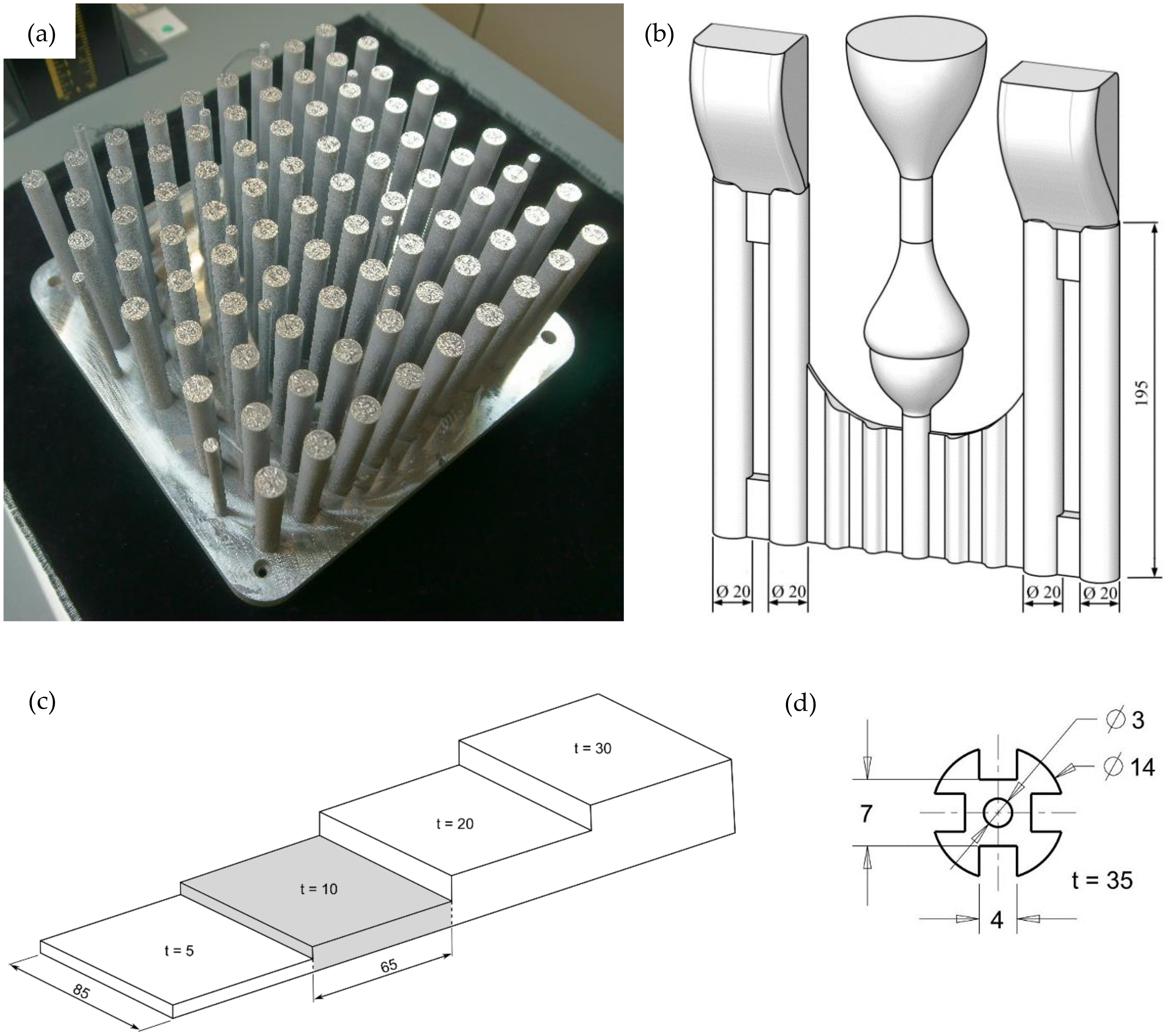
| diameter of 14 mm and 35 mm in length, with enlarged surface area as depicted in Figure 2d | up to ~9 K/s |
| Laser Powder-Bed Fused Samples | ||||
|---|---|---|---|---|
| LPBF-AlSi7Mg0.3 | LPBF-AlSi10Mg0.3 | |||
| Average | Deviation | Average | Deviation | |
| Si | 7.947 | 0.343 | 12.483 | 1.180 |
| Fe | 0.134 | 0.026 | 0.205 | 0.006 |
| Cu | 0.021 | 0.002 | 0.004 | 0.000 |
| Mn | 0.008 | 0.005 | 0.015 | 0.005 |
| Mg | 0.373 | 0.017 | 0.297 | 0.122 |
| Ni | 0.023 | 0.007 | 0.021 | 0.002 |
| Zn | 0.125 | 0.026 | 0.048 | 0.009 |
| Ti | 0.012 | 0.012 | 0.034 | 0.006 |
| Sr | 0.001 | 0.001 | 0.003 | 0.000 |
| Al | balance | balance | ||
| Cast samples | ||||
| Die-Cast AlSi7Mg0.3 | Sand-Cast AlSi7Mg0.3 | |||
| Average | Deviation | Average | Deviation | |
| Si | 6.883 | 0.361 | 7.047 | 0.281 |
| Fe | 0.098 | 0.010 | 0.151 | 0.017 |
| Cu | 0.007 | 0.001 | 0.038 | 0.008 |
| Mn | 0.007 | 0.001 | 0.027 | 0.001 |
| Mg | 0.279 | 0.045 | 0.352 | 0.047 |
| Ni | 0.006 | 0.003 | 0.006 | 0.002 |
| Zn | 0.012 | 0.008 | 0.068 | 0.020 |
| Ti | 0.116 | 0.019 | 0.106 | 0.004 |
| Sr | 0.014 | 0.004 | 0.019 | 0.002 |
| Al | balance | balance | ||
© 2020 by the authors. Licensee MDPI, Basel, Switzerland. This article is an open access article distributed under the terms and conditions of the Creative Commons Attribution (CC BY) license (http://creativecommons.org/licenses/by/4.0/).
Share and Cite
Hitzler, L.; Hafenstein, S.; Mendez Martin, F.; Clemens, H.; Sert, E.; Öchsner, A.; Merkel, M.; Werner, E. Heat Treatments and Critical Quenching Rates in Additively Manufactured Al–Si–Mg Alloys. Materials 2020, 13, 720. https://doi.org/10.3390/ma13030720
Hitzler L, Hafenstein S, Mendez Martin F, Clemens H, Sert E, Öchsner A, Merkel M, Werner E. Heat Treatments and Critical Quenching Rates in Additively Manufactured Al–Si–Mg Alloys. Materials. 2020; 13(3):720. https://doi.org/10.3390/ma13030720
Chicago/Turabian StyleHitzler, Leonhard, Stephan Hafenstein, Francisca Mendez Martin, Helmut Clemens, Enes Sert, Andreas Öchsner, Markus Merkel, and Ewald Werner. 2020. "Heat Treatments and Critical Quenching Rates in Additively Manufactured Al–Si–Mg Alloys" Materials 13, no. 3: 720. https://doi.org/10.3390/ma13030720