A Facile Synthesis of MoS2/g-C3N4 Composite as an Anode Material with Improved Lithium Storage Capacity

1
Department of Chemistry, Quy Nhon University, 170 An Duong Vuong, Quy Nhon 55100, Vietnam
2
Department of Chemistry and Nano Science, Ewha Womans University, Seoul 120-750, Korea
*
Author to whom correspondence should be addressed.
Materials 2019, 12(11), 1730; https://doi.org/10.3390/ma12111730
Submission received: 25 April 2019
/
Revised: 19 May 2019
/
Accepted: 23 May 2019
/
Published: 28 May 2019
(This article belongs to the Special Issue 2D Materials for Energy Storage and Conversion)
Abstract
:The demand for well-designed nanostructured composites with enhanced electrochemical performance for lithium-ion batteries electrode materials has been emerging. In order to improve the electrochemical performance of MoS2-based anode materials, MoS2 nanosheets integrated with g-C3N4 (MoS2/g-C3N4 composite) was synthesized by a facile heating treatment from the precursors of thiourea and sodium molybdate at 550 °C under N2 gas flow. The structure and composition of MoS2/g-C3N4 were confirmed by X-ray diffraction, scanning electron microscopy, transmission electron microscopy, infrared spectroscopy, X-ray photoelectron spectroscopy, thermogravimetric analysis and elemental analysis. The lithium storage capability of the MoS2/g-C3N4 composite was evaluated, indicating high capacity and stable cycling performance at 1 C (A·g−1) with a reversible capacity of 1204 mA·h·g−1 for 200 cycles. This result is believed the role of g-C3N4 as a supporting material to accommodate the volume change and improve charge transport for nanostructured MoS2. Additionally, the contribution of the pseudocapacitive effect was also calculated to further clarify the enhancement in Li-ion storage performance of the composite.

1. Introduction
The recently emerging demands in the fields of electronic devices and electric vehicles require advanced energy storage systems with a low cost, stability and high energy density [1]. Among the different energy storage systems, lithium-ion batteries (LIBs) with unique properties are the most promising in fulfilling these requirements [2,3]. However, the current technology of LIBs cannot satisfy the current high demand of automotive and communication industries because the commercial LIBs have limited energy density. Normally, the performance of LIBs significantly depends on the capacity and stability of electrode active materials [4]. Therefore, one of the effective strategies to improve the performance of current LIB technology is the design of novel materials with a higher theoretical capacity and the capability of rapid electrochemical kinetics [1,5].
Many materials, including elements Sn [6], Ge [7], Si [8], P [9], metal oxides [10], metal hydrides [11] and sulfides [12,13,14], have been developed as potential alternative anode materials with improved lithium-ion storage capacities. Among these anode materials, molybdenum disulfide (MoS2) has been considered as a promising candidate due to its unique properties, including much larger theoretical capacity (670 mA·h·g−1) compared to commercial graphite (372 mA·h·g−1) and capable of fast lithium-ion intercalation/deintercalation. The structure of MoS2 is similar to graphite but its larger interlaminar spacing of 0.62 nm (versus 0.34 nm for graphite) and weaker interlayer van de Waals interaction provides smooth channels for fast lithium-ion intercalation/deintercalation [5,15]. However, when used as an anode material, micro-size MoS2 suffers from several drawbacks, including low specific capacity and poor cycling stability. This is due to the large volume variation during the lithium insertion/extraction process, poor electronic conductivity and disorder of the layered structure [16,17]. These limitations hinder the practical application of MoS2 as an anode material for LIBs. To overcome these limitations, the design of nanostructured MoS2 materials such as hollow nanostructures [18], nanosheets [19] and its composites with other carbon materials such as graphene and grapheme oxide [5,20,21] have been reported. These materials exhibit the high capacity and improved stability of LIB anodes. The nanostructures are known to be effective in accommodating the volume change of MoS2 during Li insertion/extraction, thus improving reversibility and reversible capacity for MoS2. Furthermore, the supports not only cushion the internal stress induced during the volume change, but also make the composite more conductive [22,23,24,25]. Besides, the coupling of MoS2 with another material to form composites with improved electrochemical performance based on the pseudocapacitive effect attracts great attention in developing high energy storage devices [15].
Although numerous studies on the design of MoS2 composites have been reported, the robust structure of MoS2 composites as advanced LIB anode materials still remains to be investigated. At the same time, graphitic carbon nitride (g-C3N4), a type of organic polymer with a graphene-like structure, has attracted much attention in photocatalysis because of its moderate bandgap, relatively high surface area, chemical stability, low toxicity and its capacity for large production [26]. In this material, the presence of nitrogen atoms can facilitate g-C3N4 to form hydrogen bonding with other appropriate species, such as MoS2, SnS2, SnO2 and GO, forming a single hybrid material for harnessing their mutual 2D–2D molecular interactions, leading to the improved electrochemical performance of the obtained materials [22,23,24,25]. However, only a few studies have reported this material as an LIB anode material [24,25,27,28]. In this study, an MoS2/g-C3N4 composite as the LIB anode material was prepared by a one-step method, in which the mixture of precursors, sodium molybdate and thiourea was calcined at 550 °C for 1 h under N2 gas flow. For comparison, MoS2 without g-C3N4 support was also studied.
2. Materials and Methods
2.1. Preparation of Materials
All the chemicals were purchased from Sigma-Aldrich (Darmstadt, Germany) and used as received without further purification. MoS2/g-C3N4 composite was synthesized by calcining the mixture of Na2MoO4·2H2O (≥99%) and thiourea (≥99%) with a mass ratio of 1:3. In a typical synthesis, a mixture of Na2MoO4·2H2O (1.0 g) and thiourea (3.0 g) was well grinded, transferred into a ceramic crucible covered by aluminum foil and then heated in a tube furnace at 550 °C for 1 h with a heating rate of 10 °C/min under N2 gas flow. The as-prepared sample was washed with water two times and one more time with ethanol and is denoted as MS/CN. For comparison, MoS2 was prepared following the procedure for the preparation of MoS2/g-C3N4 except calcination at 600 °C for 2 h to remove g-C3N4. g-C3N4 was prepared by calcining thiourea only (without Na2MoO4) at 550 °C for 1 h under N2 gas flow. The two obtained solids were then washing with water and ethanol as mentioned above for the preparation of MS/CN and are referred to as MS and CN, respectively. A typical yield of the composite synthesis was calculated on the weight of Mo from the thermogravimetric analysis (TGA) data to be 72.97%.
2.2. Material Characterization
X-ray diffraction (XRD) analysis was carried out using a D8 Advanced Bruker anode X-ray diffractometer (Bruker, Billerica, MA, USA) with Cu Kα (λ = 1.5406 Å) radiation. The morphology of the synthesized samples was characterized by scanning electron microscopy (SEM) (JSM-600F, JEOL, Tokyo, Japan). Transmission electron microscopy (TEM) images were obtained using a JEM-2100F (JEOL, Tokyo, Japan). Infrared (IR) spectra of the samples were recorded using an IR Prestige-21 spectrophotometer (Shimadzu, Tokyo, Japan). The TGA was carried out on a SETRAM LABSYS TG system under air flow with a heating rate of 10 °C·min−1. X-ray photoelectron spectroscopy (XPS) was conducted by a Theta Probe AR-XPS system (Thermo Fisher Scientific, Waltham, MA, USA). Elemental analysis (EA) was determined with a Flash EA 1112 analyzer (Thermo Fisher Scientific, Waltham, MA, USA).
2.3. Characterization of Electrochemical Properties
The working electrodes were prepared by the following procedure. Firstly, a slurry of active material (MS/CN, MS or CN) (75 wt.%), black carbon (Ketjen black) (15 wt.%) and polyacrylic acid (MW 450,000) binder (10 wt.%) in NMP (N-methyl-2-pyrrolidone) solvent was casted onto a copper foil, dried in a vacuum oven at 110 °C for 12 h and then punched into 16 mm diameter disks. These are denoted as MS/CN, MS or CN electrodes, respectively. The mass density of active materials on the electrode was 0.9–1.0 mg·cm−2, the electrode thickness was 10–15 μm and the active material was 0.6–0.7 mg/electrode. Cyclic voltammetry (CV) was performed using three electrode cells with the working electrodes and Li metal as the counter and reference electrodes. Then, 1 M LiPF6 in ethylene carbonate:ethyl diethyl carbonate:dimethyl carbonate (3:3:4 volume ratio, Panax E-tech) containing 10 wt.% of fluoroethylene carbonate was used as the electrolyte. Cyclic voltammetry was conducted at a scan rate of 0.5 mV·s−1 in the range 0.1–3.0 V vs. Li/Li+. The electrochemical cycling performance was evaluated using a 2032 coin cell. The cell consisted of MS, MS/CN or CN electrode as a working electrode, a lithium foil as the counter electrode, electrolyte (80 μL) and a separator (Celgard 2325). The cells were assembled in an argon-filled glove-box with a water and oxygen content of <1 ppm. The cells were cycled between 0.1 and 3.0 V at a rate of C/20 (C = 1 A·g−1) for the first cycle and then charged/discharged at 1 C for an additional 200 cycles using a NAGANO BTS-2004H (Nagano Keiki Co. Ltd., Tokyo, Japan) at 25 °C. The specific capacity was calculated based on the weight of the active materials. Electrochemical impedance spectroscopy (EIS) tests were performed using a Multi Autolab/M101 (Metrohm AG, Herisau, Switzerland) with a voltage of 5 mV amplitude over a frequency range of 100 kHz to 0.01 Hz.
3. Results and Discussion
3.1. Characterization of the Materials
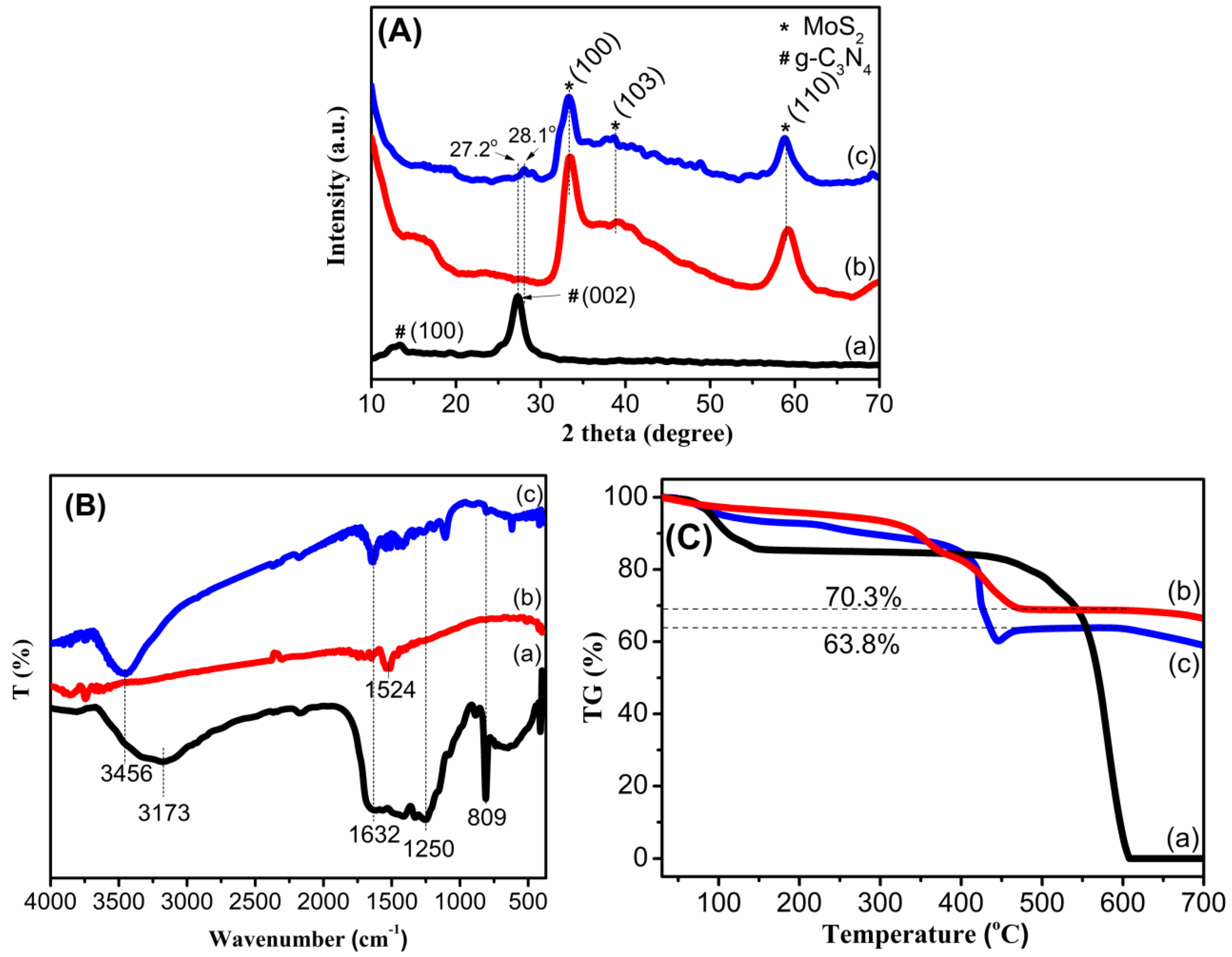
The XRD patterns of the as-prepared samples are presented in Figure 1A. For the MS sample, the pattern shows peaks at 2θ = 32.8°, 39.0° and 58.6°, which can be indexed to the (100), (103) and (110) planes, respectively, corresponding to the hexagonal phase of MoS2 (JCPDS No. 77-1716) [29,30,31]. The CN pattern exhibits two distinct diffraction peaks with a weak one at 13.2° and a strong one at 27.2°, corresponding to the tight interplanar stacking of the aromatic planes in g-C3N4 and the (002) plane of graphitic materials [29,31]. For the MS/CN composite, the peaks corresponding to the MoS2 phase are clearly observed, while the peaks belonging to g-C3N4 are strongly reduced. This may be explained by the fact that the simultaneous crystallization of MoS2 phase may interfere with the condensation process and interlayer stacking patterns of the g-C3N4 phase, thus resulting in its weak diffraction intensity [32]. Figure 1A also shows that the peak corresponding to the (002) plane of g-C3N4 in the composite shifts to a higher diffraction angle (2θ) of 28.1°, as compared with CN (2θ = 27.2°). This means that there is a reduction in the interlayer distance, indicating more dense packing of the g-C3N4 layers in the composites [33]. These results show that the layers of g-C3N4 have denser packing in the mutual formation with MoS2.
The proof of characteristic bonding vibrations in the materials was identified by IR (Figure 1B). For the CN sample, peaks at wavenumbers of about 809 cm−1, and in the range from 1250 cm−1 to 1632 cm−1, are attributed to the breathing mode of tri-s-triazine units and stretching modes of C–N and C=N bonds in aromatic rings of g-C3N4 [29,31,34,35]. These peaks were observed in MS/CN with reduced intensity. Additionally, the broad peaks centered at 3456 cm−1 are ascribed to the N–H stretching from terminal amino groups and the O–H bond from adsorbed H2O [33]. Compared to CN, the composite showed a blue shift by 283 cm−1, suggesting a change of N–H bonds in the presence of MoS2. This change may be related to the reduction of N content in MS/CN. In principle, the FTIR peak shift to a higher wavenumber may correspond to the lower mass fraction of this group. Therefore, the reduction of N-content may lead to the vanishment of the NHx peak and disclose the presence of OH bonding related to the adsorbed H2O [36]. In addition, the low wavenumber peak of NHx is related to the hydrogen bonding within and between planes. The movement of this peak to a higher region indicates that hydrogen bonding is reduced [37]. For MS, the weak peak at 1524 cm−1 is probably organic residue from the preparation.
The thermal properties of the materials were also studied by TGA. As shown in Figure 1C, the samples exhibited mass loss steps, in which the first step, from room temperature to around 120 °C, may be attributed to the evaporation of physisorbed water. For MS, two additional steps centered at 360 °C and 430 °C could be attributed to the oxidation of MoS2 to MoO3 and the decomposition of g-C3N4, respectively [38]. Noticeably, Figure 1C (c) presents two further steps for the composite, one from 200 °C to 345 °C and another from 345 °C to 450 °C, corresponding to weight losses of 6% and 26%, which may be related to the oxidation of MoS2 to MoO3 and the decomposition of g-C3N4, respectively [38]. Compared to CN (Figure 1C (a)), MS/CN exhibited weight loss at a lower temperature, suggesting that the composite possesses lower thermal stability, probably due to the crystallization disturbance of MoS2 towards interlayer stacking motifs of g-C3N4 or the catalyzing effect of MoS2 over the thermal decomposition of g-C3N4 [38]. This indicates that the structure of g-C3N4 in the composite is probably more defective compared to pure g-C3N4. A similar phenomenon was also observed in the literature [32,38]. Assuming that the final product after 600 °C is pure MoO3, the weight percent values of MoS2 active material were calculated to be 78.44% and 70.89% for MS and MS/CN, respectively.
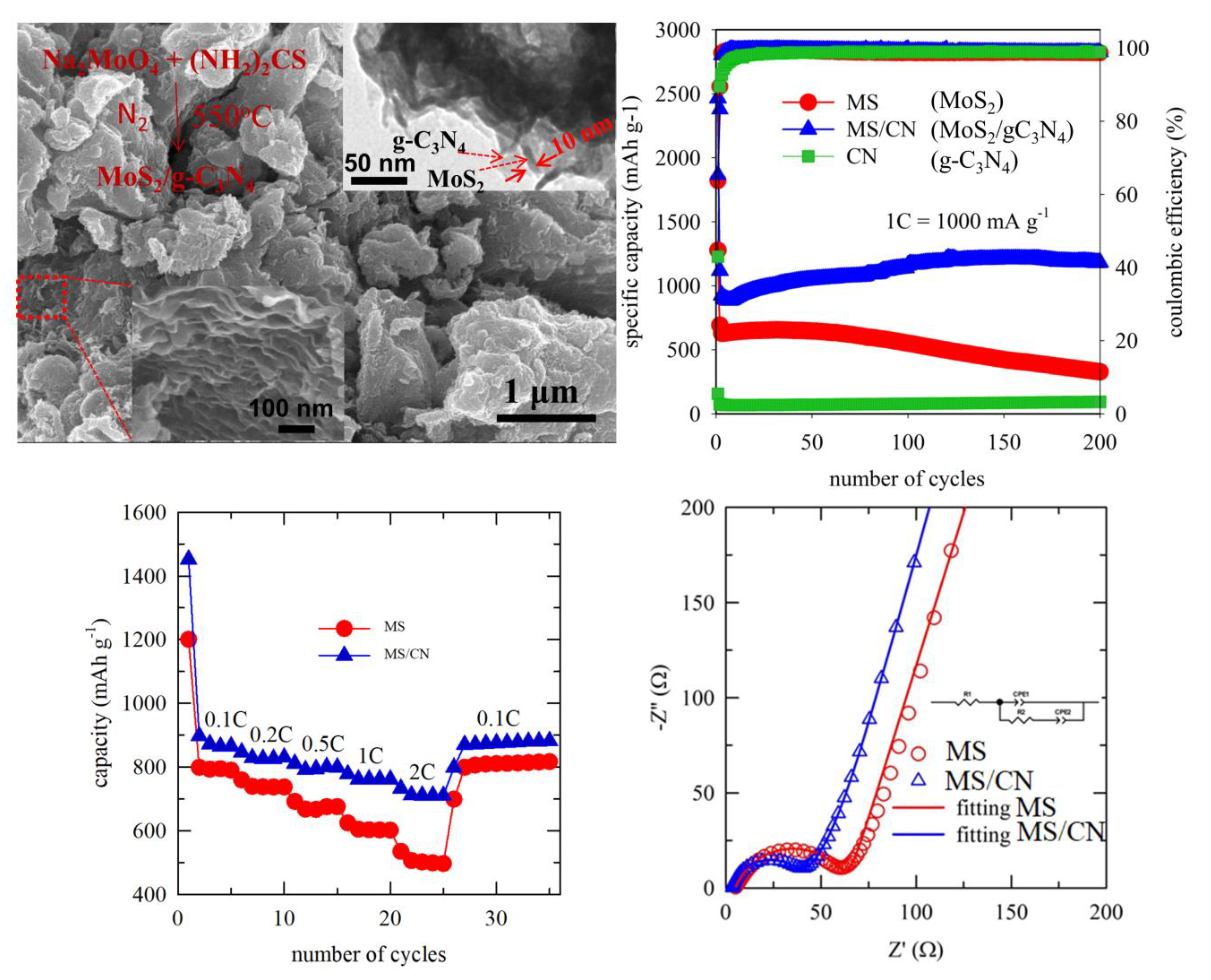
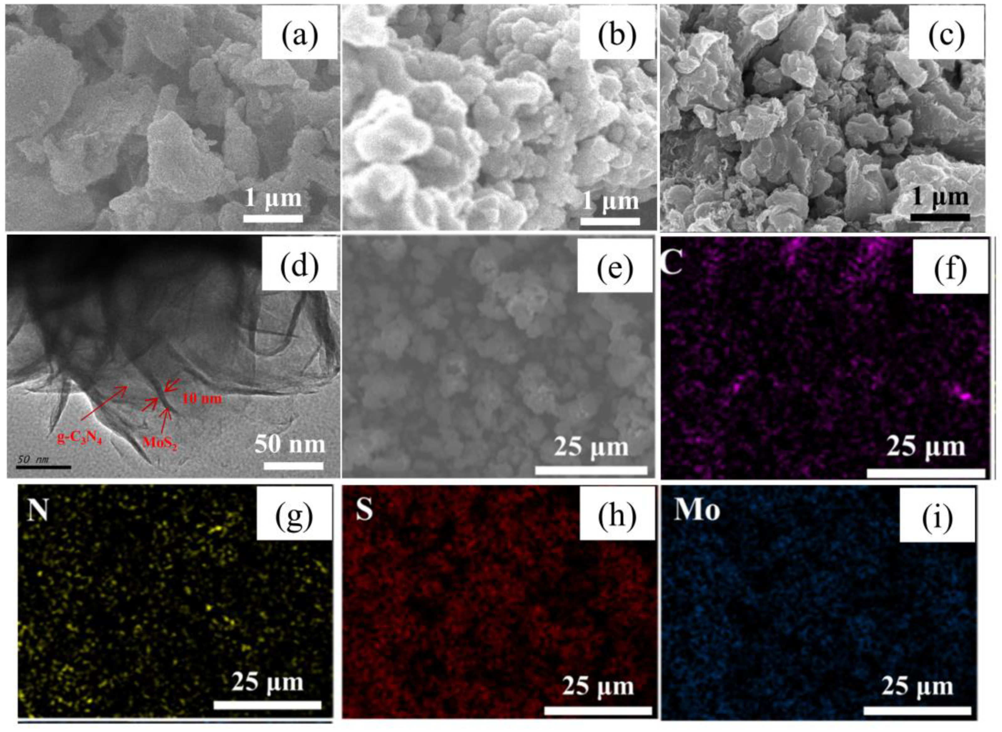
The morphology of the samples was characterized by SEM. Figure 2a shows the morphology of CN in flake form, which is in accordance with the previous report [26]. Figure 2b presents spherical particles with diameters of ~500 nm aggregating together for the MS sample. For MS/CN, Figure 2c presents a morphology that seems to be close to that of CN. This may be attributed to the fact that the surface is covered by g-C3N4. In order to further demonstrate morphology of the composite, a TEM image is also shown (Figure 2d), indicating that the MoS2 nanosheets dispersed on g-C3N4 and the thickness of the nanosheets was estimated to be in the range of 10–15 nm. The distribution of components in MS/CN was characterized by an element mapping technique (Figure 2f–i). The mapping images of carbon, nitrogen, sulfur and molybdenum elements indicate their highly homogeneous distribution in the composite.
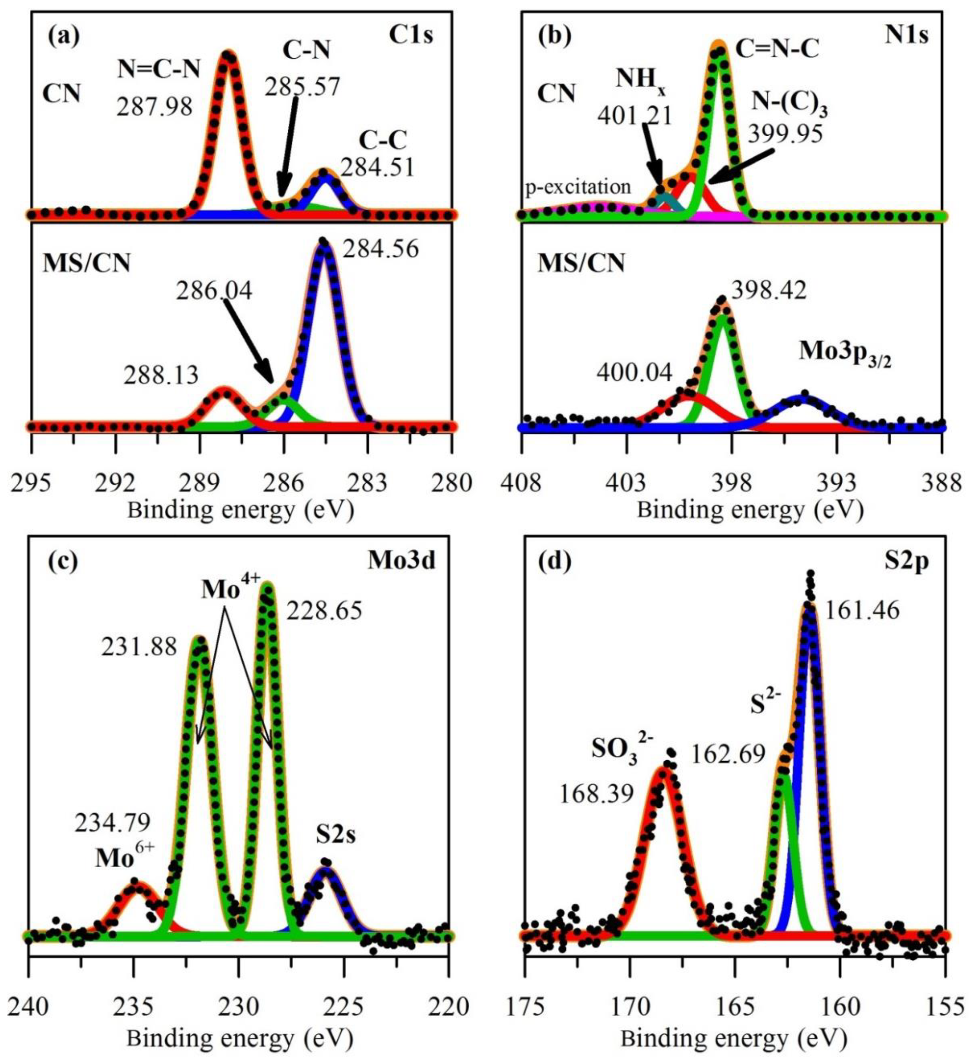
To further demonstrate the chemical composition and elemental state, XPS measurement for the composite was carried out and the results are presented in Figure 3. The C1s spectra for MS/CN could be deconvoluted into three peaks corresponding to strong one at 284.56 eV, and two weak peaks at 286.04 eV and 288.13 eV, which may be related to graphitic C–C bonding from the sample and partial contribution of the XPS instrument and aromatic sp2-C in N=C–N, respectively [39]. For comparison, the C1s XPS of CN was also exhibited in upper frame of Figure 3a, which shows that a difference in peak-intensity ratio of N=C–N versus C–C for C1s of CN and MS/CN. Particularly, the increase in intensity of the peak corresponding to C–C and C–N bonding in MS/CN comparing to pristine CN and the opposite trend of N=C–N signals lead to the conclusion that the presence of MoS2 could lead to the partly denitrogenation component and improve the graphitic characteristic of g-C3N4 [36]. This result is in agreement with the aforementioned discussion of TG-DTA and could contribute to the enhancement in electronic conductivity of composite. The N1s spectra of CN (Figure 3b) show three characteristic components, in which the one located at 398.60 eV corresponding to the sp2-hybrided N in C=N–C groups of aromatics ring, the broaden peak centered at around 399.95 eV related to the sp3-N or ternary N–(C)3 in connecting bridges between tri-s-triazine units in structure of g-C3N4 [33,40], and the minor shoulder at binding energy of 401.21 eV is ascribed as the signal of NHx-group located at edge site of g-C3N4 sheets [41]. The compassion to N1s in MS/CN show that the lower intensity as well as more broaden peak indicate that the N-content in composite in less than that of pristine sample CN while the fading of signal related to N-bonding groups reconfirms the further degradation of CN by the catalytic role of MoS2 in the synthesis temperature. In order to elucidate the reduction of N content in the composite, elemental analysis for C and N elements in CN and MS/CN was conducted, which shows atomic C/N ratios for CN and MS/CN to be 0.72 and 0.81, respectively. The broaden signal observed in the region of binding energy of 394 eV could be attributed to Mo3p3/2 [42] while there is no similar signal observed in case of CN sample. The high-resolution Mo3d spectra possess four peaks. The two high intensity peaks located in the middle region could be ascribed to the Mo3d3/2 (231.88 eV) and Mo3d5/2 (228.65 eV) demonstrating the main existence state of Mo4+ [43,44]. The low and broaden peak located at around 234.79 eV corresponding to the residual Mo6+ which is still not reduced. The last satellite peak is ascribed to the presence of S2−, which are characteristic of MoS2 [43]. The high-resolution XPS spectra of S2p can be fitted into three peaks. The peak at 168.39 eV can be attributed to S4+ species in SO32− groups, while the two main peaks 162.69 and 161.46 eV may be indexed as S2p1/2 and S2p3/2 of MoS2, respectively [45]. The presence of SO32− groups may come from oxidation of S of the thiourea precursor in the synthesis process.
3.2. Electrochemical Properties
The electrochemical properties of MS and its composite as anode materials for LIBs were investigated. It is well known that the lithium storage mechanism of MoS2 is proposed as follows [5,46,47]:
MoS2 + xLi+ + xe− → LixMoS2
LixMoS2 + (4 − x)Li+ + (4 − x)e− → Mo + 2Li2S
Mo + 2Li2S ↔ MoS2 + 4Li+ + 4e−
Li2S − 2e− ↔ S + 2Li+.
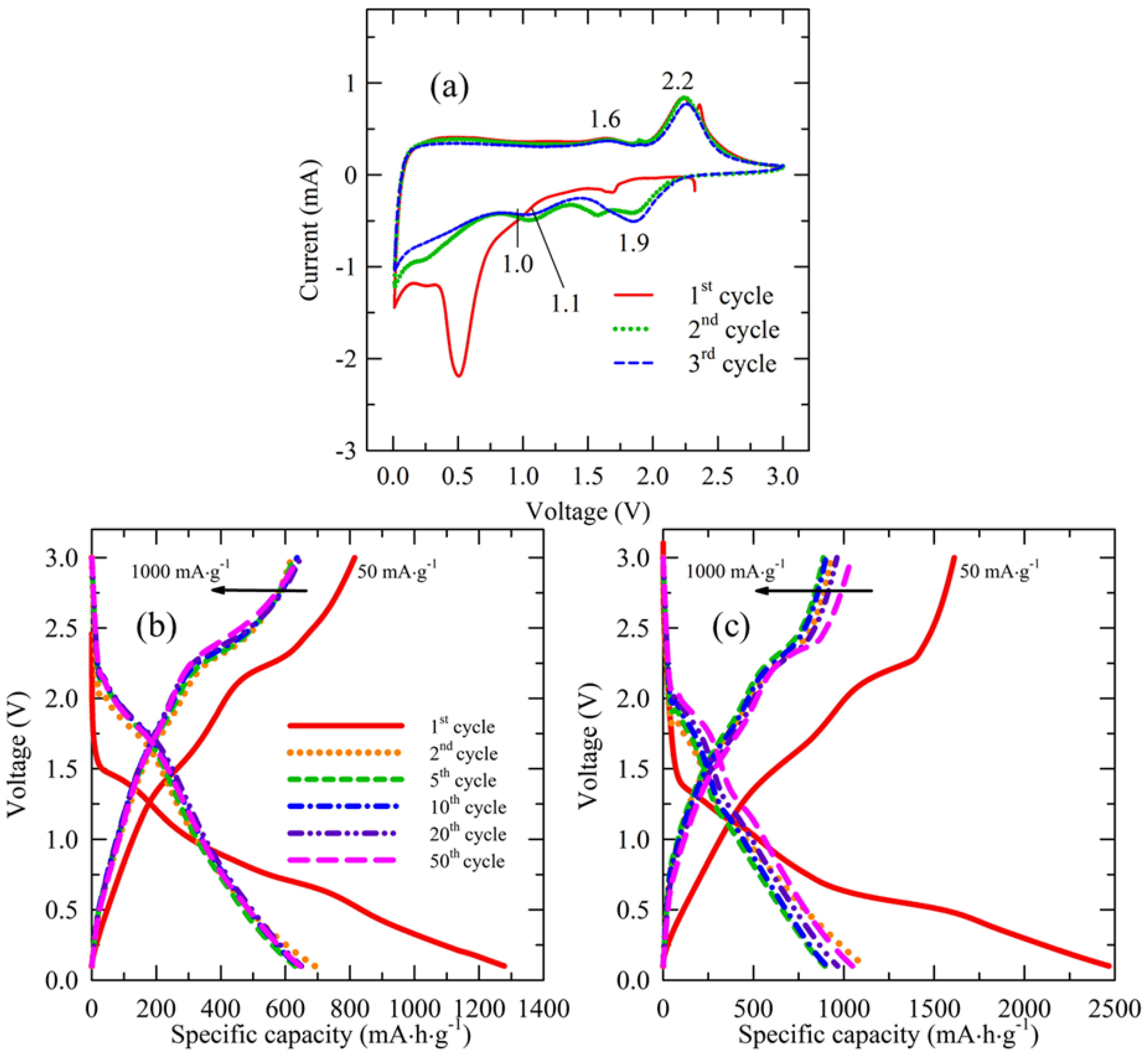
In these four reactions, the first two ones are irreversible, which occur in the first cathodic sweep process, while the latter two are reversible and present in the latter sweeps. Figure 4a shows the CV curves of the initial three cycles for MS/CN. In the first cathodic sweep process, a shoulder around 1.0 V and an intensive peak at 0.5 V are attributed to the formation of Mo and Li2S from the intercalation of Li+ into MoS2 in two irreversible steps (Equations (1) and (2)). The strong intensity of the peak at 0.5 V may come from an additional contribution of the formation of a solid electrolyte interface layer (SEI) [5]. These peaks disappear in the following cycles, indicating the irreversible processes. For the first anodic sweep, two reversible peaks, the broad peak at 1.6 V corresponding to the oxidation of Mo0 into higher states (i.e., Mo4+, Equation (3)) and a considerable peak at 2.2 V relating to the oxidation of Li2S (Equation (4)), are observed. After the first cycle, new cathodic peaks at 1.9 V and 1.1 V combining with anodic peaks at 2.2 V and 1.6 V, respectively, are assigned to two pairs of reversible redox reactions of molybdenum sulfide (Equation (3)) and sulfur (Equation (4)). It can be seen that there is a cathodic peak at ~1.6 V in the first and second cycles. These peaks could be attributed to the reduction of elemental sulfur to form Li2S [48,49]. The presence of S in the composite may come from the decomposition of thiourea during the calcination process under N2 flow for the preparation of the composite.
Figure 4b,c show the charge/discharge profiles of MS and MS/CN in the range of 0.1–3.0 V at a current density of 50 mA·g−1 for the first cycle and 1000 mA·g−1 for the next cycles. It can be seen that shape of the profiles for the two materials are similar except for the difference in specific capacities. For each, two plateaus, a slightly defined one at ~1.0 V and a clear one at 0.5 V, were observed from the discharge curve of the first cycle, probably due to the formation of LixMoS2 (Equation (1)) and Mo + 2Li2S (Equation (2)), respectively. These plateaus become indiscernible in the following cycles. For the charge curves, one significant plateau at 2.2 V and a weak one at ~1.6 V were observed, which may correspond to oxidation of Li2S (Equation (4)) and the oxidation of Mo0 into higher states (Equation (3)). These plateaus still remain in the latter cycles, indicating that they are reversible processes. These results are consistent with the CV results. A high initial discharge capacity for both materials can be ascribed to the formation of SEI layers, an irreversible process and the irreversible conversion of MoS2 (Equations (1) and (2)). The two materials exhibited that curves nearly overlap each other except for the first discharge, suggesting that cycling ability for the materials is significantly stable for the first 50 cycles. Remarkably, specific capacity of MS/CN trended upwards.
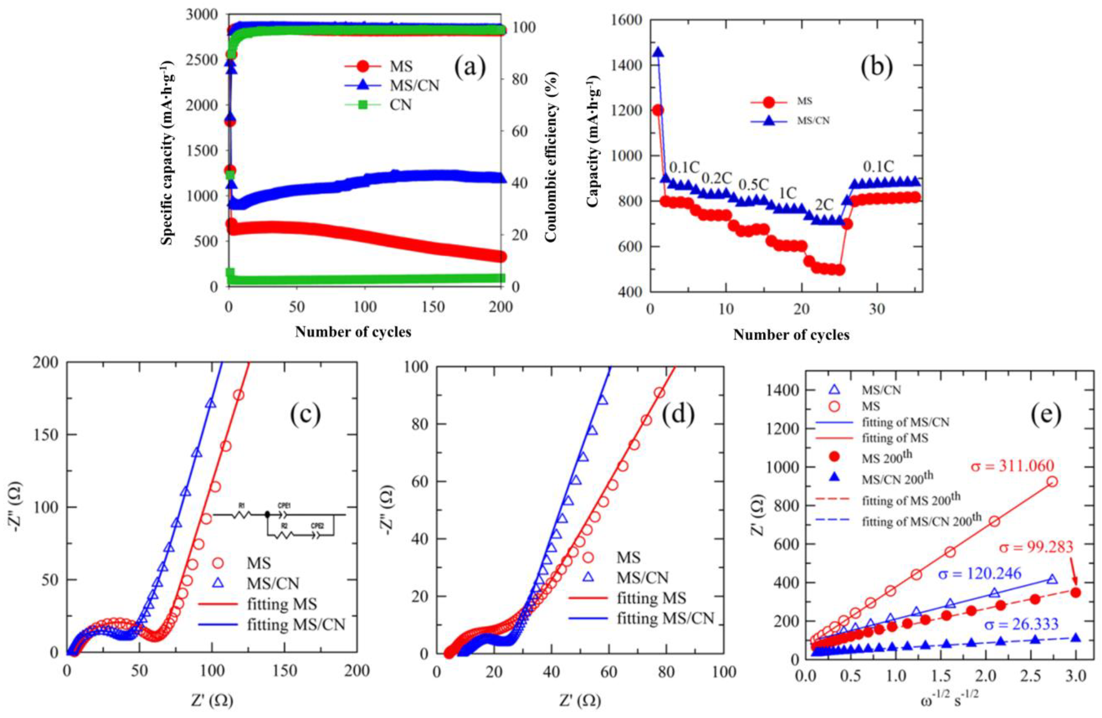
Figure 5a exhibits the cycling performance of MS and MS/CN. At the first cycle (0.05 C), the two anodes demonstrated high discharge capacities of 1278 mA·h·g−1 and 2467 mA·h·g−1 for MS and MS/CN, respectively, due to the formation of SEI layers and the irreversible conversion of MoS2. After the first cycle, the MS/CN anode exhibited an insignificant reduction within the first 10 cycles and then an upward trend of cycling performance from the reversible capacity of ~900 mA·h·g−1 at the 10th cycle to ~1204 mA·h·g−1 at the 175th cycle with a 33% increase. From the 175th to 200th cycles, the reversible capacity was constant. The rise in the capacity has been observed in other anode materials and is explained by the further activation of active materials with cycling [50], as well as the pseudocapacitive effect contribution which has been observed in various similar materials [51,52,53,54]. On the contrary, a different trend was observed for MS. After the first cycle, a reversible capacity of ~650 mA·h·g−1 was maintained until the 50th cycle. After that, a fast fading, from ~650 mA·h·g−1 at the 50th to ~326 mA·h·g−1 at the 200th cycle, could be seen. This demonstrates the superior performance of MS/CN as compared to that of the MS anode. The large surface area of supports such as g-C3N4 is well known to accommodate the volume change of MoS2 nanosheets during the lithium insertion process [22]. In addition, g-C3N4 could form a 3D conductive network in MS/CN, improving the electronic and ionic conductivity [55,56]. Therefore, an improvement in the cycling performance of the composite is probably due to the contribution of g-C3N4. The use of g-C3N4 and N-doped graphene as the supports with the active material MoS2 as LIB anode materials with high capacity retention and excellent rate capability was reported [22]. This phenomenon is attributed to the integration of mesoporous C3N4 nanosheets into the composite, which is effective in accommodating the volume variation of active material during the lithiation/delithiation, leading to an enhanced cycle performance of the electrode. In addition to the buffer layer role, g-C3N4 in the MS/CN composite with rich carbon content may be ascribed as an efficient channel for the mass transport of ions and electrolyte related to the formation of a highly uniform and stable SEI layer which, in turn, accelerates the superior cyclability [23,57,58]. A controlled electrochemical experiment using only g-C3N4 nanosheets exhibits a relatively low capacity (Figure 5a). The low capacity of pure g-C3N4 could be attributed to the fact that the insertion of Li to g-C3N4 leads to the irreversible reactions between Li and the C3N species in g-C3N4 to form Li–CH=NR and Li–N=CR2 species [59]. This could be caused by a difference between g-C3N4 in the MS/CN composite and the pure form (CN), as previously mentioned in their characterization. After the first several cycles, the Coulombic efficiencies for MS and MS/CN were improved and reached close to 99%.
Figure 5b shows the cyclic stability of the electrodes under various current rates within 35 cycles. When the current density increased from 0.1 C to 2 C, the reversible capacity showed a slight decrease for the MS/CN composite, while a significant decrease in the capacity for MS was observed. This phenomenon can be explained by the fact that the use of support g-C3N4 seems to maintain the homogeneous distribution of MoS2 against agglomeration and/or structural collapse of MoS2 nanosheets during repeated charge/discharge cycling, resulting in an improved cycling performance, especially at high rates [25]. When the current density was reversed to 0.1 C, the capacity recovery for both materials, MS and MS/CN, was very good.
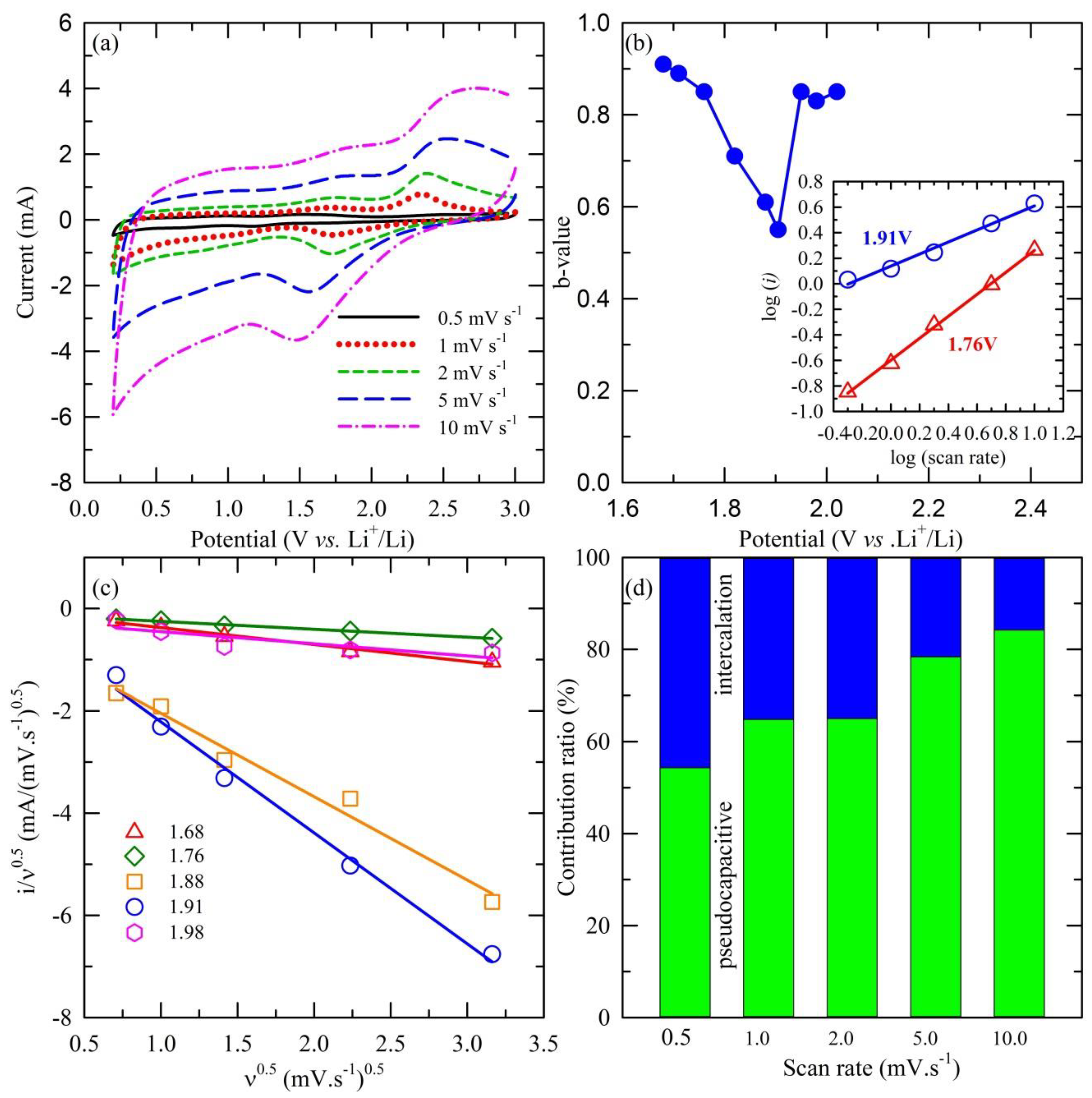
As mentioned above, the rise in the capacity for MS/CN could be attributed to the pseudocapacitive effect contribution. In order to evaluate the contribution of the pseudocapacitive and diffusion-controlled effects on the total capacity of the MS/CN sample, scan-rate-dependent CV was conducted and the obtained result is shown in Figure 6. In the theoretical concept, the total charge storage can be separated into three components: the contribution of lithium-ion intercalation, the charge-transfer process of surface atoms or the pseudocapacitive effect and the non-faradaic part of the double layer effect. By analyzing the CV of the anode at various scan rates following the equation of the power law relationship [60], we obtain:
where i is the response current (mA) at different scan rates; ν (mV·s−1) and a, b are constant. The b-value can be derived from the slope of a linear plot of log(i) vs. log(ν). At different b-values, the contribution of the pseudocapacitive effect can be verified. At b = 0.5, the response current can be substantiated following the diffusion-controlled equation or indicative of the intercalation contribution [61]:
where C* is the surface concentration of electrode materials, α is the transfer coefficient, D is the chemical diffusion coefficient, n is the number of electrons involved in the electrode reaction, A is the surface area of electrode materials, F is the Faraday constant, R is the ideal gas constant, T is the Kelvin temperature and χ(bt) is the function representing the normalized current [62].
i = aνb
i = nFAC*D1/2 ν1/2(αnF/RT)1/2π1/2χ(bt)
In another condition, such as b = 1.0, the capacitive effect is assigned based on the proportional relationship between the capacitive current and scan rate, represented by the following equation [60]:
in which Cd is the capacitance. The calculated data shown in Figure 6b indicate that the b-value at a potential of 1.9 V is 0.55, demonstrating that, at that voltage, the main contribution is the insertion process of Li+ ions. Meanwhile, at higher or lower values, b-values are in the range of 0.8 to 1.0, illustrating the dominant contribution of the capacitive effect [62,63,64,65,66].
i = CdAν
In further investigation, the contribution ratio of the pseudocapacitive effect was examined considering the concept that the response current at a fixed voltage is the combination of two distinguished mechanisms as surface capacitive and diffusion-controlled behavior, obtained via the following equation [67]:
which is adjusted to the mathematic-altering form:
i = k1ν + k2ν1/2
i/ν1/2 = k1ν1/2 + k2.
According to Equation (9), the linear plot of i/ν1/2 vs. ν1/2 at various fixed voltages in the range of 1.6 to 2.0, which covers the main peak of 1.9 V (at a scan rate of 0.5 mV·s−1), is illustrated in Figure 6c. The obtained results lead to the ability to estimate the k1 and k2 constants via the slope and y-axis intercept of extrapolation. Accordingly, the contribution of capacitive behavior in the total charge storage capacity can be quantitatively separated, as shown in Figure 6d.
To clarify the enhancement of the cycling performance for MS/CN compared to MS, the EIS measurements for the electrodes prepared from the materials were carried out. The Nyquist plots of MS and MS/CN electrodes before cycling and after 200 cycles in Figure 5c,d show that the charge transfer resistance of the MS/CN electrode possessed a smaller value than that of the MS electrode in both conditions, indicating that the presence of g-C3N4 as a support can improve electron and lithium-ion transport in MS/CN. The Li+ ion diffusion coefficient could be clarified by the Warburg coefficient, which is shown in Figure 5e. In detail, the analysis was obtained by the application of the following equations [68]:
in which σ is the Warburg coefficient, which is calculated as slope derived from the linear plot of low frequency real impedance (Z’) vs. ω−1/2; ω is the angular frequency calculated from the frequency of the obtained data; R is the ideal gas constant (8.314 J·mol−1·K−1); T is the Kelvin room temperature (298 K); n is the number of transferred electrons; A is the effective contact area of the electrode (0.636 cm2); F is the Faraday constant (96485 C·mol−1); C is the Li+ ion concentration. The impedance-related parameters obtained from EIS fitting and Warburg analysis are summarized in Table 1.
Z’ = R + σω−1/2
From the comparison, the charge transfer resistance of MS is much lower than that of MS/CN, which re-confirms the aforementioned discussion about the effect of C-rich g-C3N4 on the electronic conductivity of the composite. In addition, the significant increase of the Li+ ion diffusion coefficient of the MS/CN sample compared to MS could be evidence confirming the effect of the g-C3N4 support on the enhancement of the Li+ ion transferring ability of MoS2 in the composite.
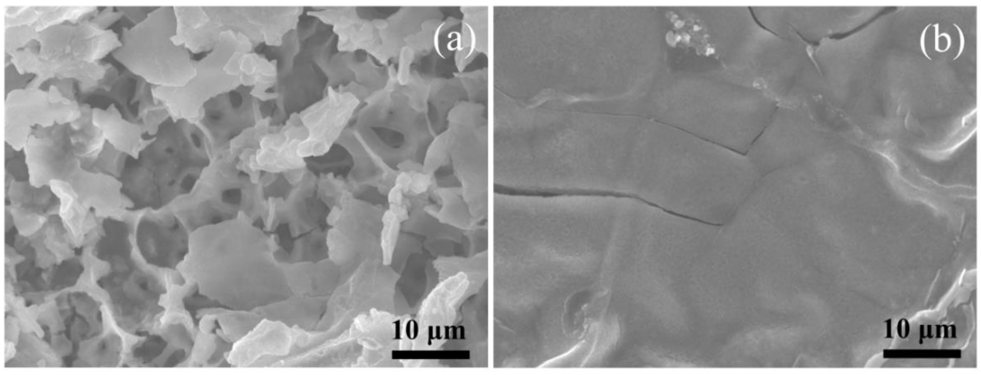
The volume change for the MS and MS/CN electrodes after 200 cycles was observed from the SEM images (Figure 7). For the MS electrode, it was broken into small fragments, while the MS/CN electrode exhibited a smooth surface with some small cracks, suggesting a larger volume change for MS electrode as compared to MS/CN. This result further supports stable cycling for the MS/CN electrode.
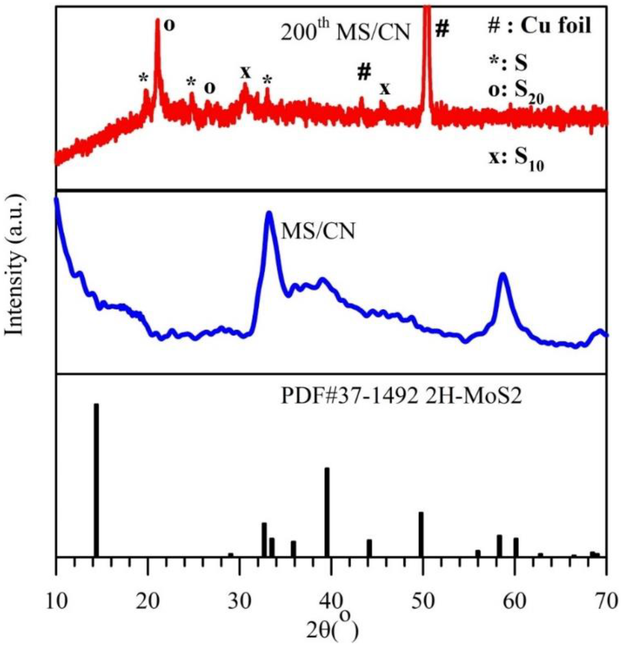
In order to support the lithium storage mechanism of MoS2 as mentioned earlier, the 200th-cycled electrode for MS/CN was characterized by ex situ XRD (Figure 8), which shows the signals corresponding to the various polymorphs of sulfur without any peak belonging to MoS2. This is reasonably ascribed to the presence of S from the equation of Li2S − 2e− ↔ S + 2Li+ (Equation (4)) and demonstrates that MoS2 was insignificantly recovered or amorphous after delithiation (Equation (3)), which agrees with the observation in the report [69].
To compare the electrochemical performance of MS/CN in this work with other materials reported elsewhere, the electrochemical performance of MoS2-based anode materials from recently published papers are listed in Table 2. It can be seen that an absolute comparison is not possible because the measurement conditions were different. However, under relative consideration, the capacity of MS/CN in this work is shown to be among the superior materials reported. Our work demonstrates that in this synthesis method, where g-C3N4 is formed simultaneously with MoS2, g-C3N4 may possess deficiencies with a rich carbon content, leading to a better conductivity than when it is formed singly.
4. Conclusions
The MoS2/g-C3N4 composite (MS/CN), consisting of MoS2 nanosheets with a wall thickness in the range of 10–15 nm and g-C3N4 in heterojunction construction, was obtained by a facile thermal treatment of a mixture of thiourea and sodium molybdate at 550 °C under N2 gas flow. In the composite, g-C3N4 possessed denser packing and deficiency of the layers with the mutual formation with MoS2. The MS/CN composite exhibited an upward trend of cycling performance with a reversible capacity of 1204 mA·h·g−1 for 200 cycles at 1 C, as compared to 326 mA·h·g−1 for MS. The significantly improved cycling performance of MS/CN compared to that of the stand-alone MoS2 is due to the presence of g-C3N4 as a supporting material to accommodate the volume change of MoS2 particles during Li+ insertion/extraction and to improve electron and lithium-ion transport in the composite. In addition, the predominant contribution of the pseudocapacitive effect was also determined as a reasonable origin for the higher specific capacity of the as-prepared composite. Our preparation route of the MoS2/g-C3N4 composite is promising for the large-scale production of advanced anode materials for LIBs.
Author Contributions
Conceptualization, V.V.; methodology, V.V., S.J.K. and H.T.H.; validation, H.T.H. and K.N.V.; formal analysis, H.T.H., X.D.N.T. and K.N.V.; investigation, H.T.H., X.D.N.T. and K.N.V.; writing—original draft preparation, V.V., S.J.K. and H.T.H.; project administration, V.V.
Funding
This research was funded by the Vietnam National Foundation for Science and Technology Development (NAFOSTED) (Grant code: 104.06-2015.94).
Conflicts of Interest
The authors declare no conflict of interest.
References
- Lu, Y.; Yu, L.; Lou, X.W.D. Nanostructured conversion-type anode materials for advanced lithium ion batteries. Chem 2018, 4, 972–996. [Google Scholar] [CrossRef]
- Zubi, G.; Dufo-López, R.; Carvalho, M.; Pasaoglu, G. The lithium-ion battery: State of the art and future perspectives. Renew. Sust. Energ. Rev. 2018, 89, 292–308. [Google Scholar] [CrossRef]
- Huang, B.; Pan, Z.; Su, X.; An, L. Recycling of lithium-ion batteries: Recent advances and perspectives. J. Power Sour. 2018, 399, 274–286. [Google Scholar] [CrossRef]
- Zhang, X.Q.; Zhao, C.Z.; Huang, J.Q.; Zhang, Q. Recent advances in energy chemical engineering of next-generation lithium batteries. Engineering 2018, 4, 831–847. [Google Scholar] [CrossRef]
- Sun, H.; Wang, J.G.; Zhang, X.; Li, C.; Liu, F.; Zhu, W.; Shao, M. Nanoconfined construction of MoS2@C/MoS2 core-sheath nanowires for superior rate and durable Li-ion energy storage. ACS Sustain. Chem. Eng. 2019, 7, 5346–5354. [Google Scholar] [CrossRef]
- Obrovac, M.N.; Chevrier, V.L. Alloy negative electrodes for Li-ion batteries. Chem. Rev. 2014, 114, 11444–11502. [Google Scholar] [CrossRef] [PubMed]
- Chan, C.K.; Zhang, X.F.; Cui, Y. High capacity li-ion battery anodes using Ge nanowires. Nano Lett. 2008, 8, 307–309. [Google Scholar] [CrossRef] [PubMed]
- Shen, X.; Tian, Z.; Fan, R.; Shao, L.; Zhang, D.; Cao, G.; Bai, Y. Research progress on silicon/carbon composite anode materials for lithium-ion battery. J. Energy Chem. 2018, 27, 1067–1090. [Google Scholar] [CrossRef] [Green Version]
- Liu, W.; Zhi, H.; Yu, X. Recent progress in phosphorus based anode materials for lithium/sodium ion batteries. Energy Storage Mater. 2019, 16, 290–322. [Google Scholar] [CrossRef]
- Mei, J.; Liao, T.; Sun, Z. Two-dimensional metal oxide nanosheets for rechargeable batteries. J. Energy Chem. 2018, 27, 117–127. [Google Scholar] [CrossRef] [Green Version]
- Cheng, Q.; Sun, D.; Yu, X. Metal hydrides for lithium-ion battery application: A review. J. Alloys Compd. 2018, 769, 167–185. [Google Scholar] [CrossRef]
- Zhao, J.; Zhang, Y.; Wang, Y.; Li, H.; Peng, Y. The application of nanostructured transition metal sulfides as anodes for lithium ion batteries. J. Energy Chem. 2018, 27, 1536–1554. [Google Scholar] [CrossRef] [Green Version]
- Xu, Q.T.; Li, J.C.; Xue, H.G.; Guo, S.P. Binary iron sulfides as anode materials for rechargeable batteries: Crystal structures, syntheses, and electrochemical performance. J. Power Sources 2018, 379, 41–52. [Google Scholar] [CrossRef]
- Huang, J.; Wei, Z.; Liao, J.; Ni, W.; Wang, C.; Ma, J. Molybdenum and tungsten chalcogenides for lithium/sodium-ion batteries: Beyond MoS2. J. Energy Chem. 2019, 33, 100–124. [Google Scholar] [CrossRef]
- Ma, K.; Jiang, H.; Hu, Y.; Li, C. 2D nanospace confined synthesis of pseudocapacitance-dominated MoS2-in-Ti3C2 superstructure for ultrafast and stable Li/Na-Ion batteries. Adv. Funct. Mater. 2018, 28, 1804306. [Google Scholar] [CrossRef]
- Fang, Y.; Lv, Y.; Gong, F.; Elzatahry, A.A.; Zheng, G.; Zhao, D. Synthesis of 2D-mesoporous-carbon/MoS2 heterostructures with well-defined interfaces for high-performance lithium-ion batteries. Adv. Mater. 2016, 28, 9385–9390. [Google Scholar] [CrossRef]
- Nethravathi, C.; Prabhu, J.; Lakshmipriya, S.; Rajamathi, M. Magnetic Co-doped MoS2 nanosheets for efficient catalysis of nitroarene reduction. ACS Omega 2017, 2, 5891–5897. [Google Scholar] [CrossRef]
- Qiu, W.; Xia, J.; He, S.; Xu, H.; Zhong, H.; Chen, L. Facile synthesis of hollow MoS2 microspheres/amorphous carbon composites and their lithium storage properties. Electrochim. Acta 2014, 117, 145–152. [Google Scholar] [CrossRef]
- Rao, C.N.R.; Maitra, U.; Waghmare, U.V. Extraordinary attributes of 2-dimensional MoS2 nanosheets. Chem. Phys. Lett. 2014, 609, 172–183. [Google Scholar] [CrossRef]
- Zhang, P.; Liu, Y.; Yan, Y.; Yu, Y.; Wang, Q.; Liu, M. A high areal capacitance for lithium ions storage achieved by a hierarchical carbon/MoS2 aerogel with vertically aligned pores. ACS Appl. Energy Mater. 2018, 1, 4814–4823. [Google Scholar] [CrossRef]
- Ma, L.; Zhao, B.; Wang, X.; Yang, J.; Zhang, X.X.; Zhou, Y.; Chen, J. MoS2 nanosheets vertically grown on the carbonized corn stalks as lithium-ion battery anode. ACS Appl. Mater. Interfaces 2018, 10, 22067–22073. [Google Scholar] [CrossRef] [PubMed]
- Hou, Y.; Li, J.; Wen, Z.; Cui, S.; Yuan, C.; Chen, J. N-doped graphene/porous g-C3N4 nanosheets supported layered-MoS2 hybrid as robust anode materials for lithium-ion batteries. Nano Energy 2014, 8, 157–164. [Google Scholar] [CrossRef]
- Shah, M.S.A.S.; Park, A.R.; Rauf, A.; Hong, S.H.; Choi, Y.; Park, J.; Yoo, P.J. Highly interdigitated and porous architected ternary composite of SnS2, g-C3N4, and reduced graphene oxide (rGO) as high performance lithium ion battery anodes. RSC Adv. 2017, 7, 3125–3135. [Google Scholar] [CrossRef]
- Tran, H.H.; Nguyen, P.H.; Cao, V.H.; Nguyen, L.T.; Tran, V.M.; Le, M.L.P.; Kim, S.J.; Vo, V. SnO2 nanosheets/graphite oxide/g-C3N4 composite as enhanced performance anode material for lithium ion batteries. Chem. Phys. Lett. 2019, 715, 284–292. [Google Scholar] [CrossRef]
- Vo, V.; Thi, X.D.N.; Jin, Y.S.; Thi, G.L.; Trung, N.T.; Quang, D.T.; Kim, S.J. SnO2 nanosheets/g-C3N4 composite with improved lithium storage capabilities. Chem. Phys. Lett. 2017, 674, 42–47. [Google Scholar] [CrossRef]
- Ong, W.J.; Tan, L.L.; Hau Ng, Y.; Yong, S.T.; Chai, S.P. Graphitic carbon nitride (g-C3N4)-based photocatalysts for artificial photosynthesis and environmental remediation: Are we a step closer to achieving sustainability? Chem. Rev. 2016, 116, 7159–7329. [Google Scholar] [CrossRef]
- Wu, M.; Wang, Q.; Sun, Q.; Jena, P. Functionalized graphitic carbon nitride for efficient energy storage. J. Phys. Chem. C 2013, 117, 6055–6059. [Google Scholar] [CrossRef]
- Senthil, S.; Kishore, S.C.; Sasidharan, M. Ultrathin MoS2 sheets supported on N-rich carbon nitride nanospheres with enhanced lithium storage properties. Appl. Surf. Sci. 2017, 410, 215–224. [Google Scholar]
- Peng, W.; Li, X. Synthesis of MoS2/g-C3N4 as a solar light-responsive photocatalyst for organic degradation. Catal. Commun. 2014, 49, 63–67. [Google Scholar] [CrossRef]
- Liu, Y.D.; Ren, L.; Qi, X.; Yang, L.W.; Hao, G.L.; Li, J.; Wei, X.L.; Zhong, J.X. Preparation, characterization and photoelectrochemical property of ultrathin MoS2 nanosheets via hydrothermal intercalation and exfoliation route. J. Alloy. Compd. 2013, 57, 37–42. [Google Scholar] [CrossRef]
- Li, J.; Liu, E.; Ma, Y.; Hu, X.; Wan, J.; Sun, L.; Fan, J. Synthesis of MoS2/g-C3N4 nanosheets as 2D heterojunction photocatalysts with enhanced visible light activity. Appl. Surf. Sci. 2016, 364, 694–702. [Google Scholar] [CrossRef]
- Yu, W.; Xu, D.; Peng, T. Enhanced photocatalytic activity of g-C3N4 for selective CO2 reduction to CH3OH via facile coupling of ZnO: A direct Zscheme mechanism. J. Mater. Chem. A 2015, 3, 19936–19947. [Google Scholar] [CrossRef]
- Papailias, I.; Giannakopoulou, T.; Todorova, N.; Demotikali, D.; Vaimakis, T.; Trapalis, C. Effect of processing temperature on structure and photocatalytic properties of g-C3N4. Appl. Surf. Sci. 2015, 358, 278–286. [Google Scholar] [CrossRef]
- Lu, X.; Jin, Y.; Zhang, X.; Xu, G.; Wang, D.; Lv, J.; Zheng, Z.; Wu, Y. Controllable synthesis of graphitic C3N4/ultrathin MoS2 nanosheets hybrid nanostructures with enhanced photocatalytic performance. Dalton Trans. 2016, 45, 15406–15414. [Google Scholar] [CrossRef] [PubMed]
- Shi, L.; Liang, L.; Wang, F.; Liu, M.; Sun, J. Enhanced photocatalytic activity of degrading rhodamine B over MoS2/g-C3N4 photocatalyst under visible light. Energy Environ. Focus 2015, 4, 74–81. [Google Scholar] [CrossRef]
- Chen, J.; Mao, Z.; Zhang, L.; Wang, D.; Xu, R.; Bie, L.; Fahlman, B.D. Nitrogen-deficient graphitic carbon nitride with enhanced performance for lithium ion battery anodes. ACS Nano 2017, 11, 12650–12657. [Google Scholar] [CrossRef]
- Zou, H.; Yan, X.; Ren, J.; Wu, X.; Dai, Y.; Sha, D.; Pan, J.; Liu, J. Photocatalytic activity enhancement of modified g-C3N4 by ionothermal copolymerization. J. Mater. 2015, 1, 340–347. [Google Scholar] [CrossRef]
- Liu, Y.; Xu, X.; Zhang, J.; Zhang, H.; Tian, W.; Li, X.; Tade, M.O.; Sun, H.; Wang, S. Flower-like MoS2 on graphitic carbon nitride for enhanced photocatalytic and electrochemical hydrogen evolutions. Appl. Catal. B 2018, 239, 334–344. [Google Scholar] [CrossRef]
- Zang, Y.; Li, L.; Li, X.; Lin, R.; Li, G. Synergistic collaboration of g-C3N4/SnO2 composites for enhanced visible-light photocatalytic activity. Chem. Eng. J. 2014, 246, 277–286. [Google Scholar] [CrossRef]
- Mo, Z.; She, X.; Li, Y.; Liu, L.; Huang, L.; Chen, Z.; Zhang, Q.; Xu, H.; Li, H. Synthesis of g-C3N4 at different temperatures for superior visible/UV photocatalytic performance and photoelectrochemical sensing of MB solution. RSC Adv. 2015, 5, 101552–101562. [Google Scholar] [CrossRef]
- Liu, H.; Chen, D.; Wang, Z.; Jing, H.; Zhang, R. Microwave-assisted molten-salt rapid synthesis of isotype triazine-/heptazine based g-C3N4 heterojunctions with highly enhanced photocatalytic hydrogen evolution performance. App. Catal. B Environ. 2017, 203, 300–313. [Google Scholar] [CrossRef]
- Li, R.; Yang, L.; Xiong, T.; Wu, Y.; Cao, L.; Yuan, D.; Zhou, W. Nitrogen doped MoS2 nanosheets synthesized via a low-temperature process as electrocatalysts with enhanced activity for hydrogen evolution reaction. J. Power Sour. 2017, 356, 133–139. [Google Scholar] [CrossRef]
- Zheng, D.; Zhang, G.; Hou, Y.; Wang, X. Layering MoS2 on soft hollow g-C3N4 nanostructures for photocatalytic hydrogen evolution. Appl. Catal. A 2016, 521, 2–8. [Google Scholar] [CrossRef]
- Zhao, L.; Jia, J.; Yang, Z.; Yu, J.; Wang, A.; Sang, Y.; Zhou, W.; Liu, H. One-step synthesis of CdS nanoparticles/MoS2 nanosheets heterostructure on porous molybdenum sheet for enhanced photocatalytic H2 evolution. Appl. Catal. B 2017, 210, 290–296. [Google Scholar] [CrossRef]
- Vrubel, H.; Merki, D.; Hu, X. Hydrogen evolution catalyzed by MoS3 and MoS2 particles. Energy Environ. Sci. 2012, 5, 6136–6144. [Google Scholar] [CrossRef]
- Xu, X.; Fan, Z.; Yu, X.; Ding, S.; Yu, D.; Lou, X.W.D. A nanosheets-on-channel architecture constructed from MoS2 and CMK-3 for high-capacity and long-cycle-life lithium storage. Adv. Energy Mater. 2014, 4, 1400902. [Google Scholar] [CrossRef]
- Chang, K.; Chen, W. In situ synthesis of MoS2/graphene nanosheet composites with extraordinarily high electrochemical performance for lithium ion batteries. Chem. Commun. 2011, 47, 4252–4254. [Google Scholar] [CrossRef] [PubMed]
- Stephenson, T.; Li, Z.; Olsen, B.; Mitlin, D. Lithium ion battery applications of molybdenum disulfide (MoS2) nanocomposites. Energy Environ. Sci. 2014, 7, 209–231. [Google Scholar] [CrossRef]
- Li, N.; Liu, Z.; Gao, Q.; Li, X.; Wang, R.; Yan, X.; Li, Y. In situ synthesis of concentric C@MoS2 core–shell nanospheres as anode for lithium ion battery. J. Mater. Sci. 2017, 52, 13183–13191. [Google Scholar] [CrossRef]
- Debela, T.T.; Lim, Y.R.; Seo, H.W.; Kwon, I.S.; Kwak, I.H.; Park, J.; Cho, W.I.; Kang, H.S. Two-dimensional WS2@Nitrogen-doped graphite for high performance lithium ion batteries: experiments and molecular dynamics simulations. ACS Appl. Mater. Interfaces 2018, 10, 37928–37936. [Google Scholar] [CrossRef] [PubMed]
- Cook, J.B.; Kim, H.S.; Yan, Y.; Ko, J.S.; Robbennolt, S.; Dunn, B.; Tolbert, S.H. Mesoporous MoS2 as a transition metal dichalcogenide exhibiting pseudocapacitive Li and Na-ion charge storage. Adv. Energy Mater. 2016, 6, 1501937. [Google Scholar] [CrossRef]
- Pei, J.; Geng, H.; Ang, E.H.; Zhang, L.; Cao, X.; Zheng, J.; Gu, H. Controlled synthesis of hollow C@TiO2@MoS2 hierarchical nanospheres for high-performance lithium-ion batteries. Nanoscale 2018, 10, 17327–17334. [Google Scholar] [CrossRef] [PubMed]
- Wu, N.; Tian, W.; Shen, J.; Qiao, X.; Sun, T.; Wu, H.; Zhao, J.; Liu, X.; Zhang, Y. Facile fabrication of a jarosite ultrathin KFe3(SO4)2(OH)6@rGO nanosheet hybrid composite with pseudocapacitive contribution as a robust anode for lithium-ion batteries. Inorg. Chem. Front. 2019, 6, 192–198. [Google Scholar] [CrossRef]
- Wang, J.G.; Liu, H.; Zhou, R.; Liu, X.; Wei, B. Onion-like nanospheres organized by carbon encapsulated few-layer MoS2 nanosheets with enhanced lithium storage performance. J. Power Sour. 2019, 413, 327–333. [Google Scholar] [CrossRef]
- Wang, C.; Sawicki, M.; Emani, S.; Liu, C.; Shaw, L.L. Na3MnCO3PO4—A high capacity, multi-electron transfer redox cathode material for sodium ion batteries. Electrochim. Acta 2015, 161, 322–328. [Google Scholar] [CrossRef]
- Wang, C.; Sawicki, M.; Kaduk, J.A.; Shaw, L.L. Roles of processing, structural defects and ionic conductivity in the electrochemical performance of Na3MnCO3PO4 cathode material. J. Electrochem. Soc. 2015, 162, A1601–A1609. [Google Scholar] [CrossRef]
- Liu, K.; Man, J.; Cui, J.; Zhang, H.; Li, T.; Yang, J.; Wen, Z.; Sun, J. Li4Ti5O12/g-C3N4 composite with an improved lithium storage capability. Mater. Lett. 2019, 234, 117–120. [Google Scholar] [CrossRef]
- Wang, G.; Wen, Z.; Yang, Y.-E.; Yin, J.; Kong, W.; Li, S.; Sun, J.; Ji, S. Ultra-long life Si@rGO/g-C3N4 with a multiply synergetic effect as an anode material for lithium-ion batteries. J. Mater. Chem. A 2018, 6, 7557–7565. [Google Scholar] [CrossRef]
- Veith, G.M.; Baggetto, L.; Adamczyk, L.A.; Guo, B.; Brown, S.S.; Sun, X.G.; Albert, A.A.; Humble, J.R.; Barnes, C.E.; Bojdys, M.J.; et al. Electrochemical and solid-state lithiation of graphitic C3N4. Chem. Mater. 2013, 25, 503–508. [Google Scholar] [CrossRef]
- Lindstrom, H.; Sodergren, S.; Solbrand, A.; Rensmo, H.; Hjelm, J.; Hagfeldt, A.; Lindquist, S.E. Li+ ion insertion in TiO2 (Anatase). 2. Voltammetry on nanoporous films. J. Phys. Chem. B 1997, 101, 7717–7722. [Google Scholar] [CrossRef]
- Bard, A.J.; Faulkner, L.R. Electrochemical Method: Fundamentals and Applications; John Wiley & Sons: New York, NY, USA, 1980. [Google Scholar]
- Wang, J.; Polleux, J.; Lim, J.; Dunn, B. Pseudocapacitive contributions to electrochemical energy storage in TiO2 (Anatase) nanoparticles. J. Phys. Chem. C 2007, 111, 14925–14931. [Google Scholar] [CrossRef]
- Yu, F.; Liu, Z.; Zhou, R.; Tan, D.; Wang, H.; Wang, F. Pseudocapacitance contribution in boron-doped graphite sheets for anion storage enables high-performance sodium-ion capacitors. Mater. Horiz. 2018, 5, 529–535. [Google Scholar] [CrossRef]
- Xiang, Y.; Yang, Z.; Wang, S.; Hossain, M.S.A.; Yu, J.; Kumar, N.A.; Yamauchi, Y. Pseudocapacitive behavior of the Fe2O3 anode and its contribution to high reversible capacity in lithium ion batteries. Nanoscale 2018, 10, 18010–18018. [Google Scholar] [CrossRef]
- Wang, R.; Wang, S.; Peng, X.; Zhang, Y.; Jin, D.; Chu, P.K.; Zhang, L. Elucidating the intercalation pseudocapacitance mechanism of MoS2-carbon monolayer interoverlapped superstructure: toward high-performance sodium-ion-based hybrid supercapacitor. ACS Appl. Mater. Interfaces 2017, 9, 32745–32755. [Google Scholar] [CrossRef] [PubMed]
- Cook, J.B.; Kim, H.-S.; Lin, T.C.; Lai, C.-H.; Dunn, B.; Tolbert, S.H. Pseudocapacitive charge storage in thick composite MoS2 nanocrystal-based electrodes. Adv. Energy Mater. 2017, 7, 1601283. [Google Scholar] [CrossRef]
- Liu, T.C.; Pell, W.G.; Conway, B.E.; Roberson, S.L. Behavior of Molybdenum Nitrides as Materials for Electrochemical Capacitors: Comparison with Ruthenium Oxide. J. Electrochem. Soc. 1998, 145, 1882–1888. [Google Scholar] [CrossRef]
- Lee, Y.-W.; Kim, D.-M.; Kim, S.-J.; Kim, M.-C.; Choe, H.-S.; Lee, K.H.; Sohn, J.I.; Cha, S.N.; Kim, J.M.; Park, K.-W. In-situ synthesis and characterization of Ge embedded electrospun carbon nanostructures as high performance anode material for lithium-ion batteries. ACS Appl. Mater. Interfaces 2016, 8, 7022–7029. [Google Scholar] [CrossRef] [PubMed]
- Sen, U.K.; Johari, P.; Basu, S.; Nayak, C.; Mitra, S. An experimental and computational study to understand the lithium storage mechanism in molybdenum disulfide. Nanoscale 2014, 6, 10243–10254. [Google Scholar] [CrossRef]
Figure 1.
(A): XRD patterns of (a) CN, (b) MS and (c) MS/CN; (B): IR spectra of (a) CN, (b) MS and (c) MS/CN (c); (C) TGA curves of (a) CN, (b) MS and (c) MS/CN.
Figure 1.
(A): XRD patterns of (a) CN, (b) MS and (c) MS/CN; (B): IR spectra of (a) CN, (b) MS and (c) MS/CN (c); (C) TGA curves of (a) CN, (b) MS and (c) MS/CN.

Figure 2.
SEM images of (a) CN, (b) MS and (c) MS/CN; (d) TEM image of MS/CN; (e) selected area for mapping, (f) carbon, (g) nitrogen, (h) sulfur and (i) molybdenum element mapping images of MS/CN.
Figure 2.
SEM images of (a) CN, (b) MS and (c) MS/CN; (d) TEM image of MS/CN; (e) selected area for mapping, (f) carbon, (g) nitrogen, (h) sulfur and (i) molybdenum element mapping images of MS/CN.

Figure 3.
X-ray photoelectron spectroscopy (XPS) spectra of (a) C1s, (b) N1s for MS/CN and CN; (c) Mo3d and (d) S2p for MS/CN.
Figure 3.
X-ray photoelectron spectroscopy (XPS) spectra of (a) C1s, (b) N1s for MS/CN and CN; (c) Mo3d and (d) S2p for MS/CN.

Figure 4.
(a) Cyclic voltammogram curves in the voltage range 0.1–3.0 V at a scan rate of 0.5 mV·s−1 of MS/CN for the first three cycles; galvanostatic discharge/charge profiles of (b) MS and (c) MS/CN for the first 50 cycles.
Figure 4.
(a) Cyclic voltammogram curves in the voltage range 0.1–3.0 V at a scan rate of 0.5 mV·s−1 of MS/CN for the first three cycles; galvanostatic discharge/charge profiles of (b) MS and (c) MS/CN for the first 50 cycles.

Figure 5.
(a) Cycling performance, (b) rate performances, (c) Nyquist plots for the initial MS and MS/CN electrode, (d) Nyquist plots for the MS and MS/CN electrode after 200 cycles and (e) Warburg coefficient plots for the initial state and after 200 cycles of the MS and MS/CN electrodes.
Figure 5.
(a) Cycling performance, (b) rate performances, (c) Nyquist plots for the initial MS and MS/CN electrode, (d) Nyquist plots for the MS and MS/CN electrode after 200 cycles and (e) Warburg coefficient plots for the initial state and after 200 cycles of the MS and MS/CN electrodes.

Figure 6.
(a) Voltammetric responses, (b) b-values as a function of potential for cathodic sweeps (Li+ insertion) (inset: power law dependence of current on sweep rate shows good linearity), (c) analysis of the cathodic voltammetric sweep data and (d) intercalation and capacitive contributions for the MS/CN electrode.

Figure 7.
SEM images of the electrode based on (a) MS and (b) MS/CN after 200 cycles at 0.05 C for the first cycle and 1 C for the next cycles.
Figure 7.
SEM images of the electrode based on (a) MS and (b) MS/CN after 200 cycles at 0.05 C for the first cycle and 1 C for the next cycles.

Figure 8.
XRD patterns of MS/CN, MS/CN electrode after 200 cycles and reference of MoS2.


Table 1.
Fitted values of the corresponding parameters of the anode electrodes.
| Sample | Rs (Internal Ohmic Resistance) (Ω) | Rct (Charge Transfer Resistance) (Ω) | Warburg Coefficient (Ω·s−1/2) | Li+ Ion Diffusion Coefficient DLi+ (cm2·s−1/2) |
|---|---|---|---|---|
| Initial MS | 4.651 | 60.017 | 311.060 | 9.05 × 10⁻¹³ |
| Initial MS/CN | 3.333 | 40.887 | 120.246 | 6.05 × 10⁻¹² |
| 200th MS | 4.424 | 33.025 | 99.283 | 8.88 × 10⁻¹² |
| 200th MS/CN | 4.279 | 35.017 | 26.333 | 1.26 × 10⁻¹⁰ |
Table 2.
Comparison of electrochemical performances of MoS2-based anode materials.
| Sample | Initial Discharge Capacity | Cycle Number | Rate | Reversible Capacity | Ref. |
|---|---|---|---|---|---|
| MS/CN | 2467 mA·h·g−1 | 200 | 1 C | 1204 mA·h·g−1 | This work |
| VA-C/MoS2 | 678 mA·h·g−1 | 1000 | 5 A·g−1 | 613 mA·h·g−1 | [20] |
| g-C3N4/MoS2 | 2390 mA·h·g−1 | 50 | 0.1 C | 864 mA·h·g−1 | [28] |
| MoS2/CCS | 1409.5 mA·h·g−1 | 250 | 100 mA·g−1 | 1230.9 mA·h·g−1 | [21] |
| MoS2MACC | 1245.4 mA·h·g−1 | 100 | 100 mA·g−1 | 1147 mA·h·g−1 | [18] |
| C@TiO2@MoS2 | 1687 mA·h·g−1 | 100 | 200 mA·g−1 | 993.2 mA·h·g−1 | [52] |
© 2019 by the authors. Licensee MDPI, Basel, Switzerland. This article is an open access article distributed under the terms and conditions of the Creative Commons Attribution (CC BY) license (http://creativecommons.org/licenses/by/4.0/).
Share and Cite
MDPI and ACS Style
Tran Huu, H.; Nguyen Thi, X.D.; Nguyen Van, K.; Kim, S.J.; Vo, V. A Facile Synthesis of MoS2/g-C3N4 Composite as an Anode Material with Improved Lithium Storage Capacity. Materials 2019, 12, 1730. https://doi.org/10.3390/ma12111730
AMA Style
Tran Huu H, Nguyen Thi XD, Nguyen Van K, Kim SJ, Vo V. A Facile Synthesis of MoS2/g-C3N4 Composite as an Anode Material with Improved Lithium Storage Capacity. Materials. 2019; 12(11):1730. https://doi.org/10.3390/ma12111730
Chicago/Turabian StyleTran Huu, Ha, Xuan Dieu Nguyen Thi, Kim Nguyen Van, Sung Jin Kim, and Vien Vo. 2019. "A Facile Synthesis of MoS2/g-C3N4 Composite as an Anode Material with Improved Lithium Storage Capacity" Materials 12, no. 11: 1730. https://doi.org/10.3390/ma12111730
Note that from the first issue of 2016, this journal uses article numbers instead of page numbers. See further details here.