
Design of a Home Fire Detection System Using Arduino and SMS Gateway

 ,
,  , ,
, ,  and
and
Abstract
:1. Introduction
2. Methodology
2.1. System Analysis
2.1.1. Running System Analysis
- The first step for the community or building owner is to detect a fire by looking at the smoke and flames coming from the building.
- The second step is the building owner/local community looking for contact information/phone number for firefighters.
- The second step is the building owner/community contacting the firefighters by telephone to ask for help (phone calls will continue until the firefighters are successfully contacted).
- The fire brigade responds to the community/fire victims. The current fire fighting process does not involve an early detection of fires so that actions are taken based on reports that a fire has occurred. Thus, it has been confirmed that a serious fire has occurred and property damage has occurred, and there may even be fatalities before the officers respond to fire information. Thus, it is necessary to involve a mechanism to be able to provide early warning information about a fire.
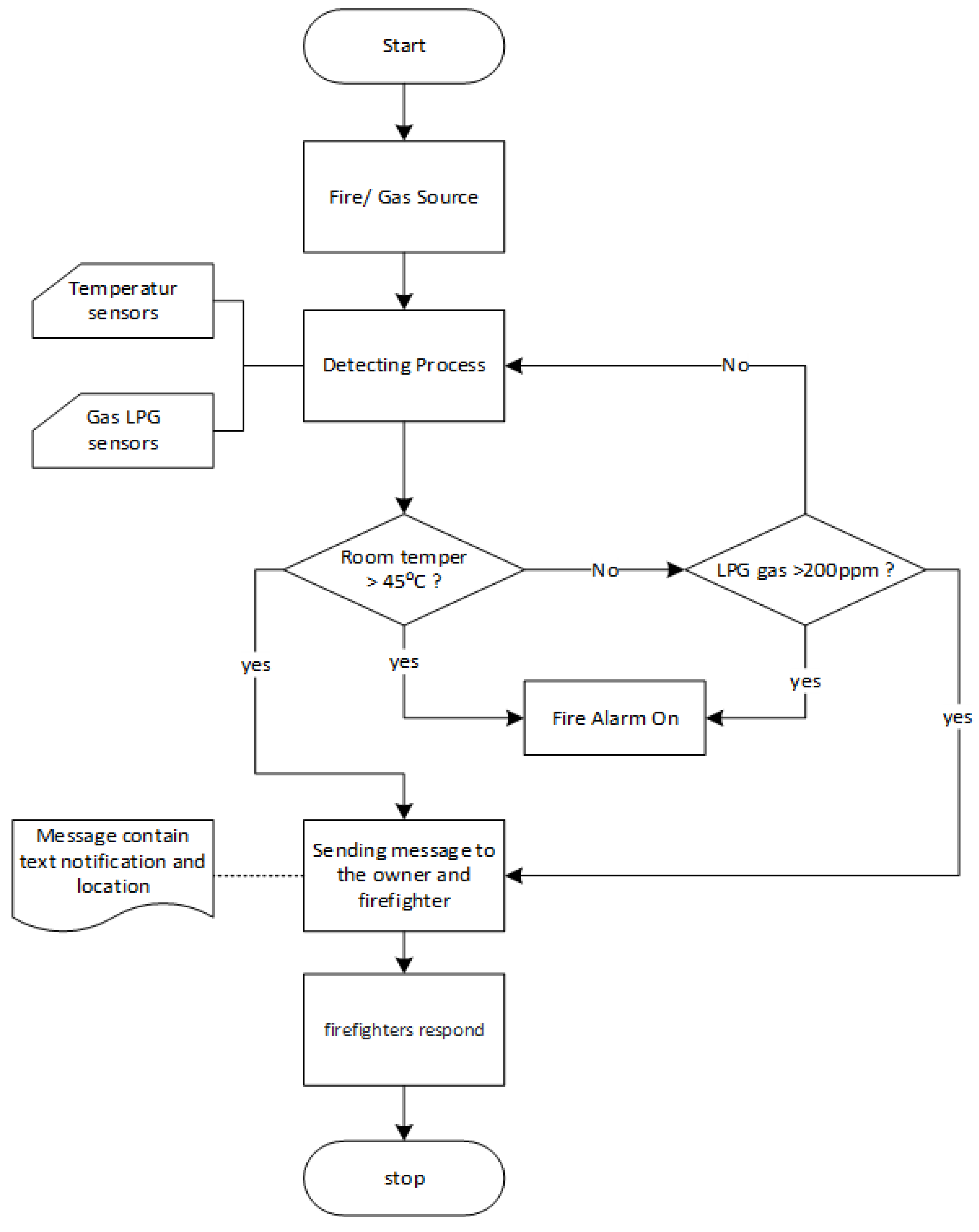
2.1.2. Proposed System Analysis
- In the first stage, the tool detects the presence or absence of a potential fire by measuring the temperature in the room using a temperature sensor.
- In the second stage, if the room temperature is detected above >45 °C, the system will activate the siren/alarm indicating a potential fire as well as sending a text message containing information on potential fires and also the coordinates for the detection of potential fires via the GSM module to the homeowner and also the fire department’s office whose calling number has been registered on the device.
- The next step is if the detected room temperature is not more than 45 °C, the system will detect the potential for an explosion/or fire by measuring the level of LPG gas in the room using an LPG gas sensor.
- The next step is if it is detected that LPG gas spreading in the room is at 220 ppm, the system will activate the siren/alarm per sign of a potential explosion as well as send a text message containing information on the potential for an explosion to occur to the homeowner via the GSM module.
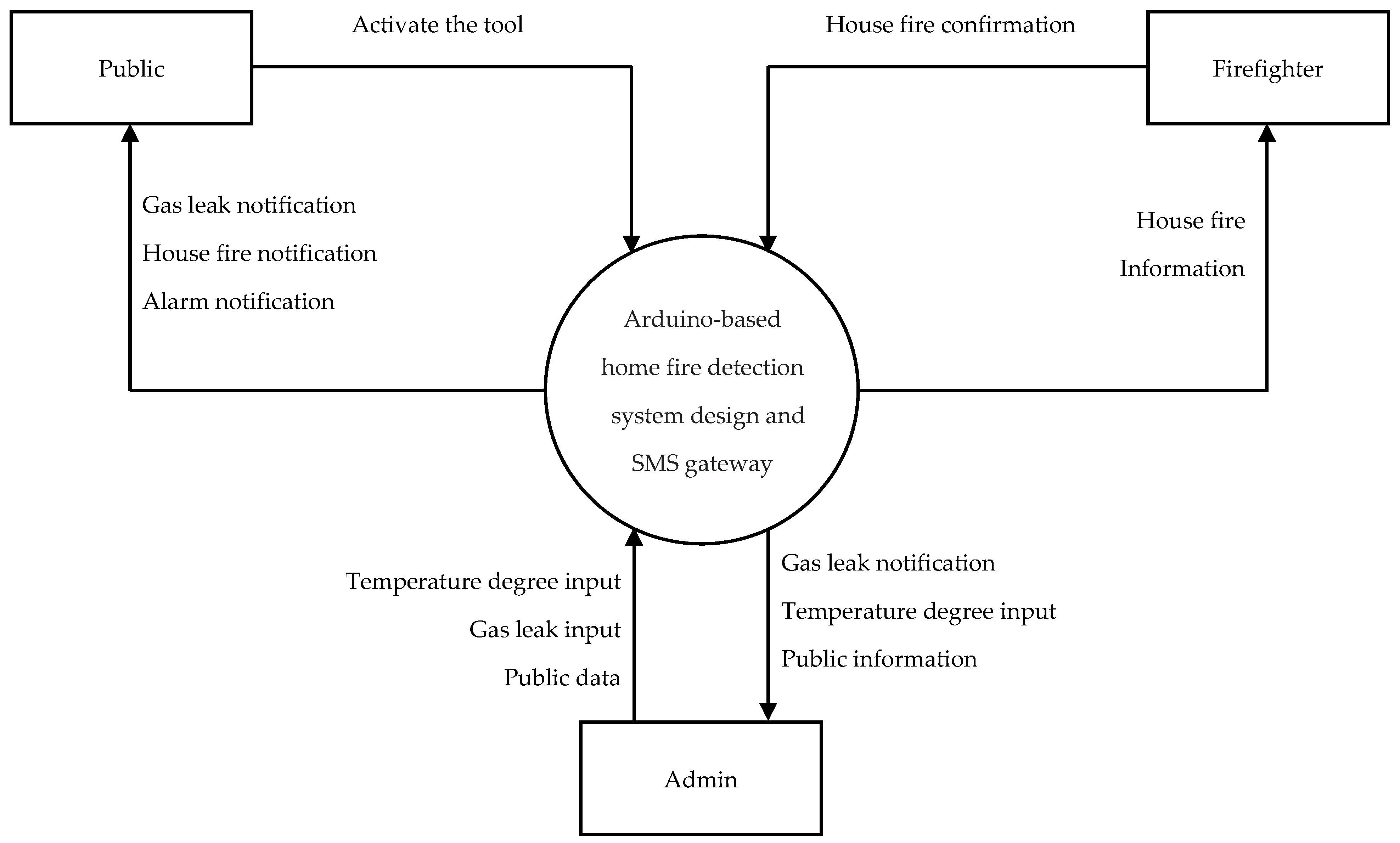
2.1.3. Requirement Analysis
- A short message will be sent automatically if the system has recognized a potential fire.
- The system will send a short message to the house owner and the fire department containing the house fire location.

| No | Requirements | Information |
|---|---|---|
| 1 | Hardware | Intel Core i3-7020U Processor, 2.3 GHz |
| 1 TB Hard Drive | ||
| RAM 4 GB | ||
| 1366 × 768 pixel HD Resolution Monitor Screen | ||
| Keyboard and Mouse | ||
| 2 | Software | Windows 10 Operating System |
| Arduino IDE | ||
| Edraw Max 7.9 |
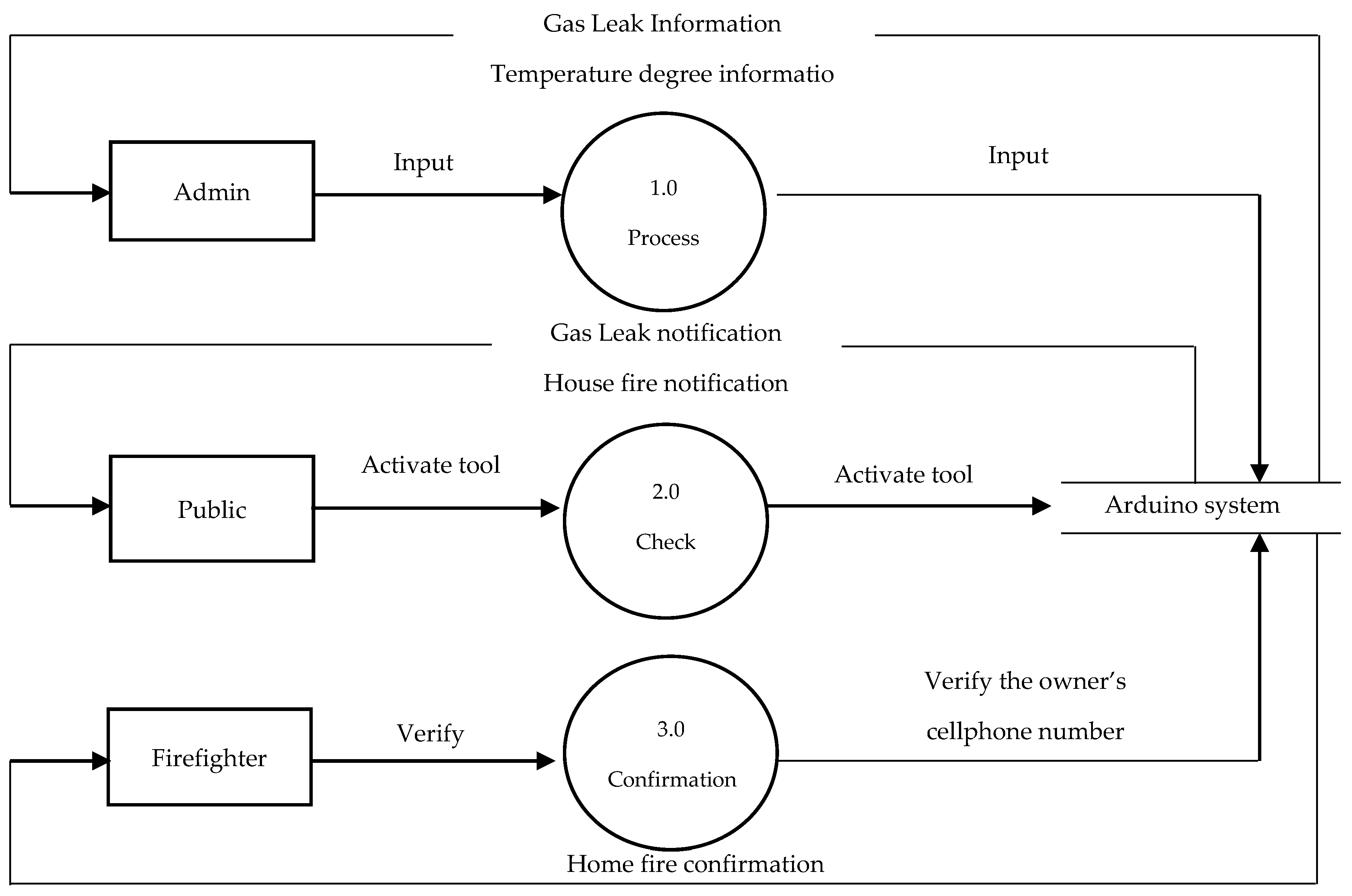
2.2. Software Design
3. Results and Discussion
System Implementation
- Research concept
- 2.
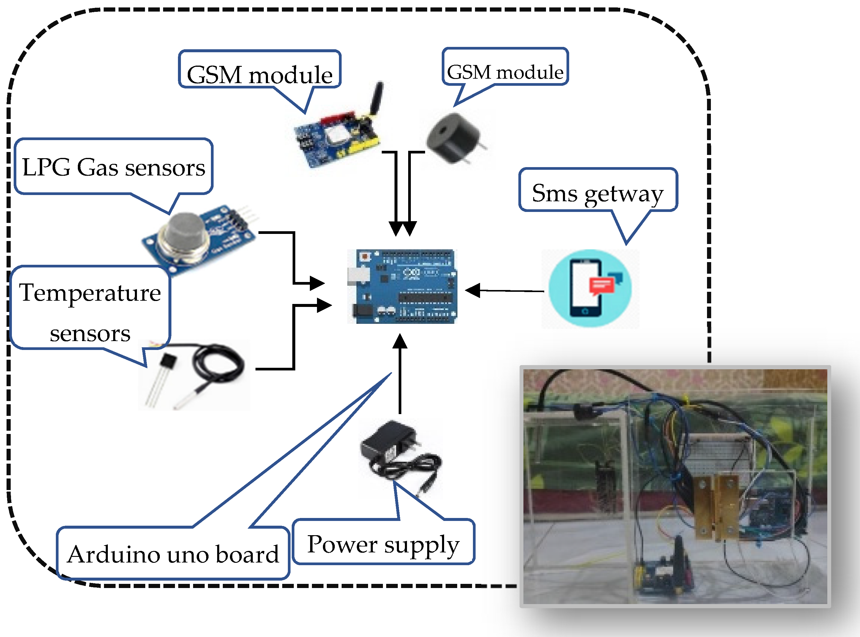
- Device design used
- Arduino Uno R3 Atmega328p
- Sensor DS18B20
- Sensor MQ2
- GSM module Sim900
- Active buzzer 5 V–12 V
- Adapter 12 V–1 A
- Alkaline Battery 9 V
- 3.
- Tool design
- Arduino UNO R3: The function of Arduino UNO R3 itself is as the control and decision-making center of the fire detection system. The operation of the system is made from a program and then uploaded to the Arduino Uno R3 to be done so that the connected input and output devices can operate according to the previously uploaded program.
- DS18B20 sensor: The function of the DS18B20 sensor is to identify the room temperature in the home fire detection system. After detecting an increase in temperature above >45 °C in the room, the data becomes the input for Arduino Uno R3 and further action will be taken for the next process.
- MQ2 sensor: The function of the MQ2 sensor is to identify gas levels in the room. Detection of this sensor will be input for Arduino Uno R3 and further action will be taken for the next process.
- GSM module: The GSM function used in the design of this system is to send information in the form of a short message ordered by Arduino Uno R3 when Arduino gets input from both sensors, namely the MQ2 sensor and the DS18B20 sensor.
- Buzzer: Serves as a warning so that homeowners can hear or be aware of the condition of the house.
- Adapter 12 V–1 A: Serves to convert AC voltage to mid-DC, which provides power so that the Arduino Uno R3 and GSM modules can work properly.
- 9 V battery: Serves to supply and provide electricity to the Arduino system and GSM module when the adapter does not work.
- 1.
- Program flow design
- Stage 1: Microcontroller initialization
- Stage 2: Initialization of DS18B20 and MQ2 sensors
- Stage 3: GSM module initialization
- Stage 4: Buzzer initialization
- Stage 5: Room temperature identification
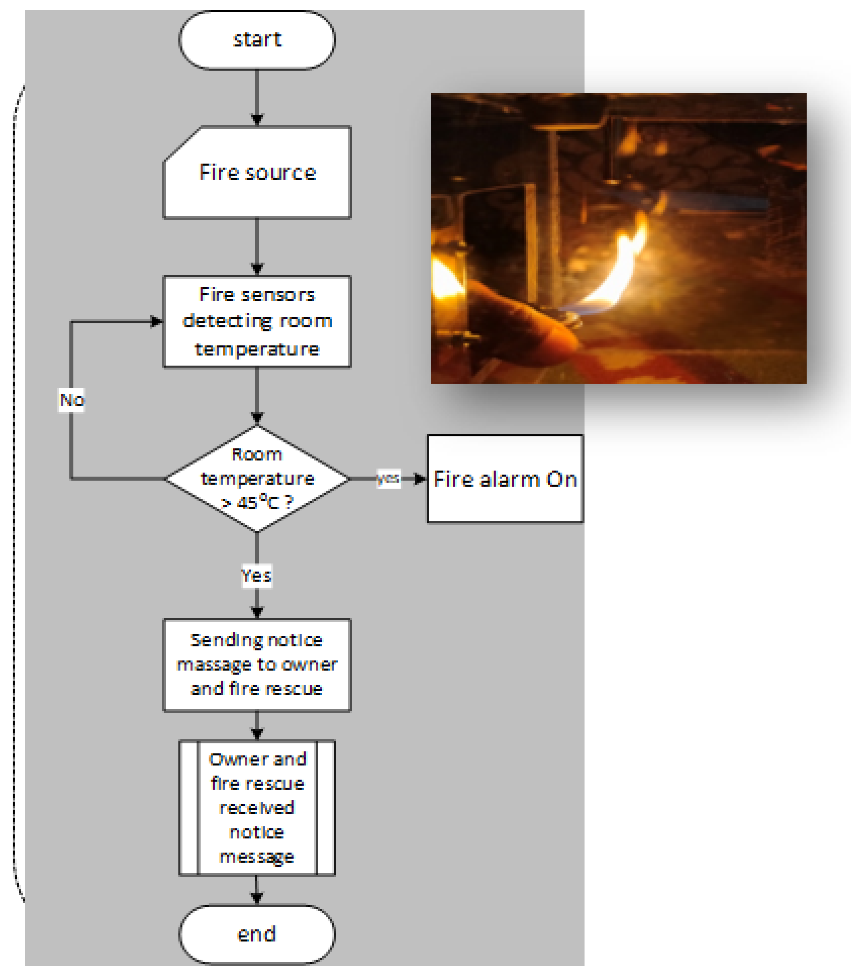
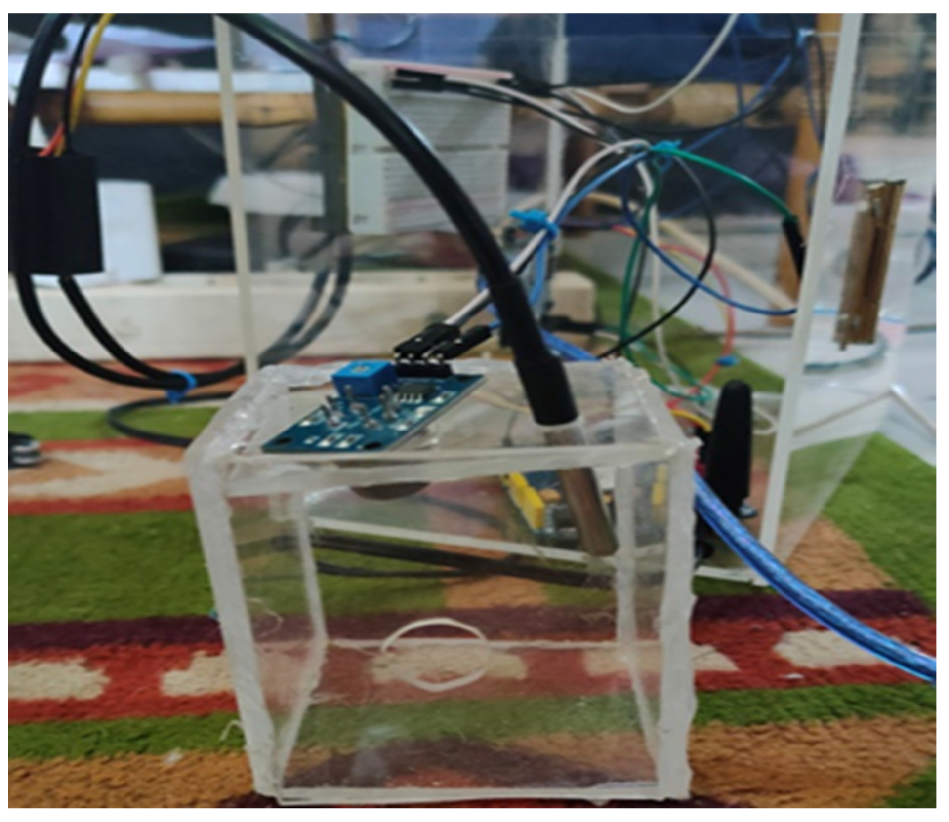
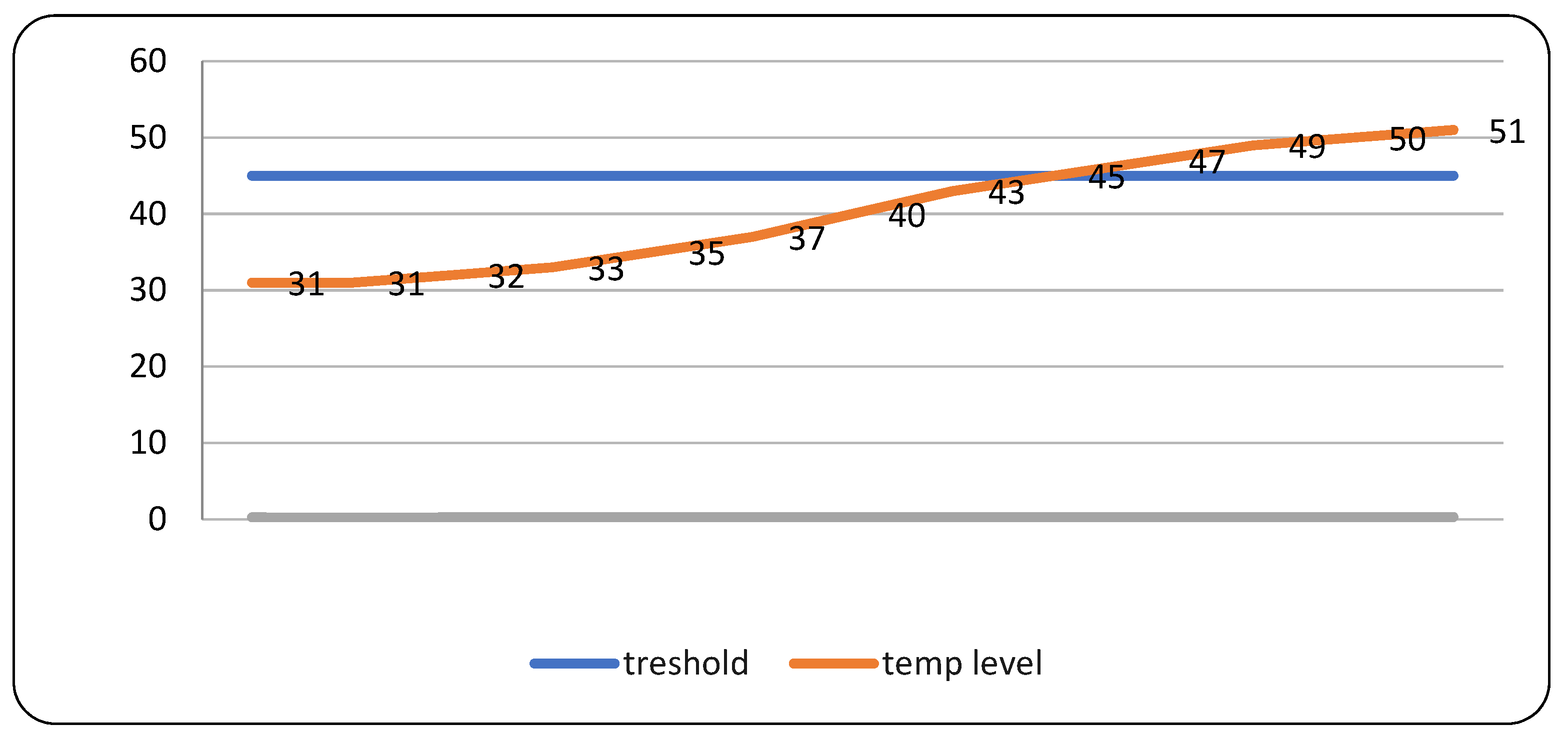
- The initial stage is the presence of a fire source in a box that has been fitted with a heat detection sensor as shown in the photo in the chart above. The fire was lit for a while until the temperature in the room increased. The temperature sensor then detects an increase in room temperature, the temperature sensor will tolerate an increase in temperature up to 45 °C, if the temperature has exceeded that value (>45 °C), then the temperature sensor will send that value to the Arduino microcontroller board which then responds to the input by doing two actions at once.
- The first action is the buzzer activation command. The buzzer will sound an alarm signaling a potential fire in the room.
- The second action is an order to send a short message through the GSM model with the SMS gateway method to homeowners and fire officers, which contains messages in the form of information on potential fires and the coordinates of the potential fire points.
- The system will again take temperature measurements and will not give orders to turn on the buzzer and send short messages if the detected temperature has not exceeded the value of 45 °C.
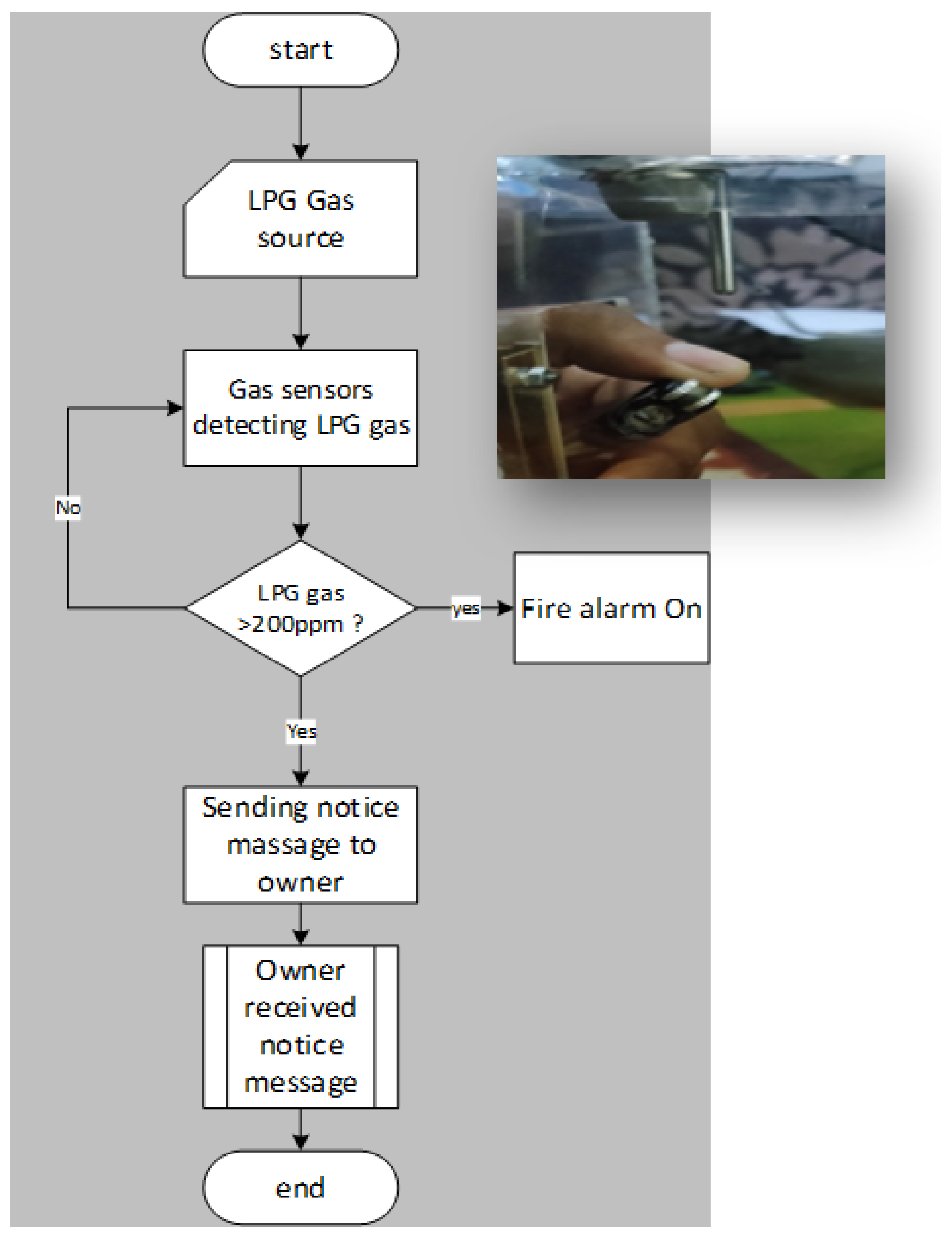
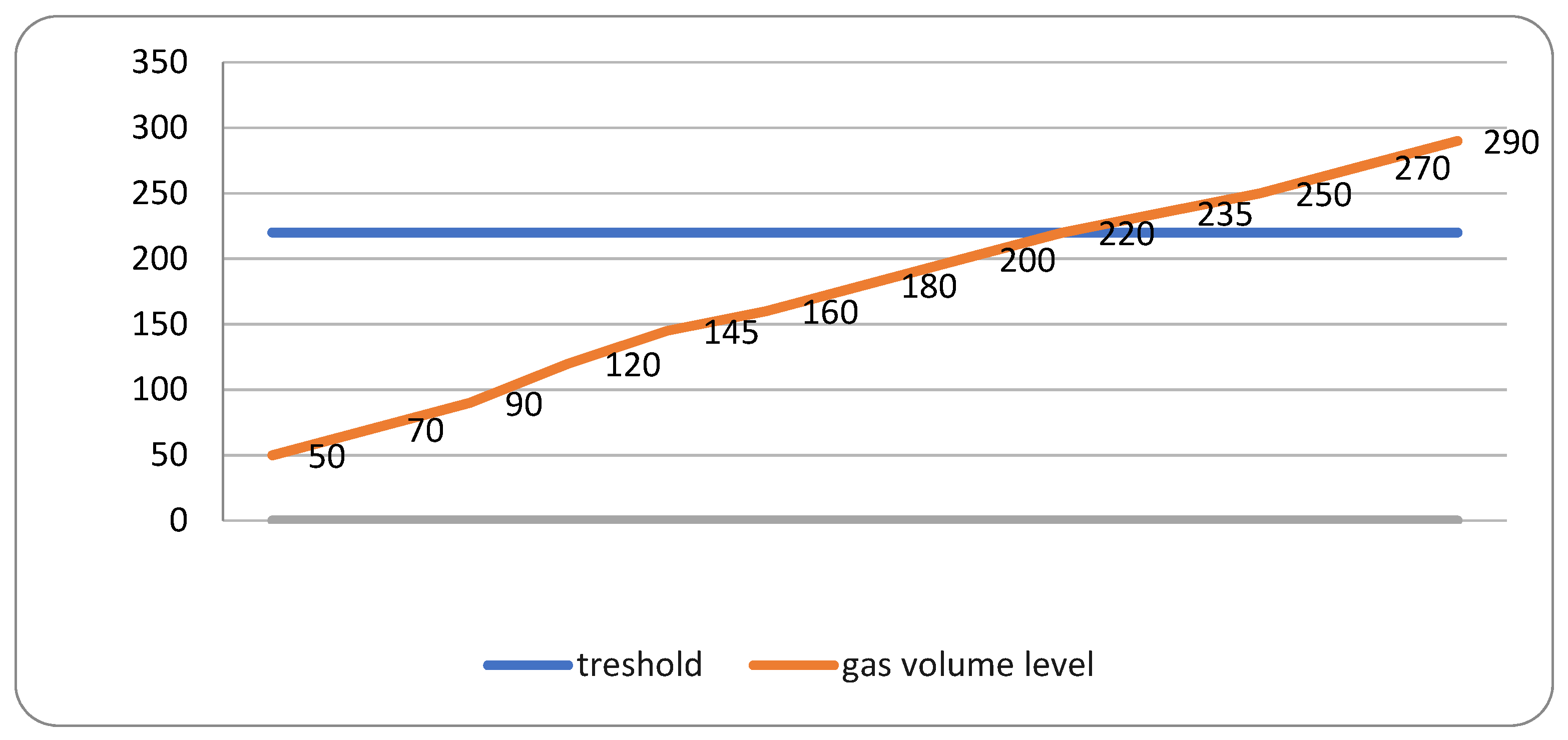
- The initial stage is the presence of a gas source (LPG) in a box that has been fitted with a heat detection sensor as shown in the photo above. The gas valve is opened for a while until the gas fills the space/box. The gas sensor then detects an increase in the volume of gas in the room/box, the gas sensor will tolerate an increase in gas volume up to 220 ppm, if the gas volume has exceeded this value (>220 ppm), then the gas sensor will send the value to the Arduino microcontroller board which then responds to the input by performing two actions at once.
- The first action is the buzzer activation command. The buzzer will sound an alarm signaling a potential fire in the room.
- The second action is an order to send a short message through the GSM model with the SMS gateway method to the homeowner, which contains a message in the form of information on potential explosions/fires due to gas leaks.
- The system will again measure the gas volume and will not give the order to turn on the buzzer and send a short message if the detected gas volume has not exceeded the 220 ppm value.
- 2.
- Sensor calibration test
- The first scenario testing is on a scale of 1 to 75
- Testing the second scenario with a scale of 1 to 50
- Testing the third scenario with a scale of 1 to 25
- 3.
- Black box test
- -
- MQ2 sensor interpretation went well, and output worked as planned. The system sends a short message to the homeowner.
- -
- In the DS18B20 reading test, the sensor can read and measure the condition of the room at the time of measurement in a standard temperature room and a hot room (>45 °C). The measurements taken have sent a short message to homeowners and firefighters.
- -
- The buzzer can work according to the instructions given, which is to sound an alarm when the room temperature reaches the maximum limit.
- 4.
- System test
- 1.
- Test scenario Room temperature level with a threshold of 45 °C
- -
- Test duration 60 min
- -
- Room size = W: 3.5 m × H: 2.5 sqm
- -
- Heat introduction: Maspion MV-250 NEX exhaust fan
- 2.
- Test scenarios LPG gas level with a threshold of 151 ppm
- -
- Test duration 30 min
- -
- Room temperature level (threshold >45 °C)
- -
- Room size = W: 3.5 m × H: 2.5 sqm
- -
- Gas source, 12 kg LPG cylinder
- -
- SNI standard regulator gas valve (Indonesian national standard)
- -
- JL-269-C. gas detector gauge
4. Conclusions
Author Contributions
Funding
Acknowledgments
Conflicts of Interest
References
- BNPB. Defenisi Bencana. bnpb.go.id. 2021. Available online: https://bnpb.go.id/definisi-bencana (accessed on 25 May 2021). (In Bahasa).
- Kodur, V.; Kumar, P.; Rafi, M.M. Fire hazard in buildings: Review, assessment and strategies for improving fire safety. PSU Res. Rev. 2019, 4, 1–23. [Google Scholar] [CrossRef]
- Ding, L.; Khan, F.; Ji, J. Risk-based safety measure allocation to prevent and mitigate storage fire hazards. Process. Saf. Environ. Prot. 2020, 135, 282–293. [Google Scholar] [CrossRef]
- Zandamela, A.A. An Approach to Smart Home Security System Using Ardunio. Electr. Eng. Int. J. 2017, 4, 1–18. [Google Scholar] [CrossRef]
- Saeed, F.; Paul, A.; Rehman, A.; Hong, W.H.; Seo, H. IoT-Based Intelligent Modeling of Smart Home Environment for Fire Prevention and Safety. J. Sens. Actuator Netw. 2018, 7, 11. [Google Scholar] [CrossRef] [Green Version]
- Kamelia, L.; Ismail, N.; Firmansyah, A.A. Fire disaster early detection system in residential areas. J. Phys. Conf. Ser. 2019, 1402, 044001. [Google Scholar] [CrossRef]
- Hillary, R.; Rotich, P.; Geofrey, A.; Sam, A. Early Fire Detection System in Tanzania Markets. In Proceedings of 7th International Electronic Conference on Sensors and Applications; MDPI: Basel, Switzerland, 2020; Volume 2, p. 50. [Google Scholar]
- Sasmoko, D.; Mahendra, A. Rancang bangun sistem pendeteksi kebakaran berbasis iot dan sms gateway menggunakan arduino. Simetris J. Tek. Mesin, Elektro dan Ilmu Komput. 2017, 8, 469. [Google Scholar] [CrossRef] [Green Version]
- Utomo, B.T.W.; Saputra, D.S. Saputra, Simulasi Sistem Pendeteksi Polusi Ruangan Menggunakan Sensor Asap Dengan Pemberitahuan Melalui SMS (Short Message Service) Dan Alarm Berbasis Arduino. J. Ilm. Teknol. Inf. Asia 2016, 10, 56–68. [Google Scholar]
- Nurnaningsih, D. Pendeteksi Kebocoran Tabung LPG Melalui SMS Gateway Menggunakan Sensor MQ-2 Berbasis Arduino Uno. J. Tek. Inform. 2018, 11, 121–126. [Google Scholar] [CrossRef]
- Santosa, E.; Budiyanta, A.S. Rancang Bangun Sensor Suhu Tanah dan Kelembaban Udara. J. Sains Dirgant. 2009, 7, 201–213. [Google Scholar]
- Suherman, S.; Andriyanto, I.; Dwiyatno, S. Rancang Bangun Alat Ukur Temperatur Suhu Perangkat Server Menggunakan Sensor Lm35 Bebasis Sms Gateway. Prosisko 2015, 2, 42–63. [Google Scholar]
- Christian, J.; Komar, N. Prototipe Sistem Pendeteksi Kebocoran Gas LPG Menggunakan Sensor Gas MQ2, Board Arduino Duemilanove, Buzzer, dan Arduino GSM Shield pada PT. Alfa Retailindo (Carrefour Pasar Minggu). J. Ticom 2013, 2, 58–64. [Google Scholar]
- Aep Nurul Hidayah. DEFINISI PERANCANGAN By Aep Nurul Hidayah. 2016. Available online: www.aepnurulhidayat.wordpress.com (accessed on 23 September 2021).
- Irawan, S.P. Pelajari Tentang Sensor Suhu DS18B20 Dan Bagaimana Penyambungan Alat Tersebut Sebagai Input Pada Perangkat Raspberry Pi Sebagai Sensor Suhu Sebuah Ruangan. kl801.ilearning.me. 2017. Available online: https://kl801.ilearning.me/2017/02/26/pelajari-tentang-sensor-suhu-ds18b20-dan-bagaimana-penyambungan-alat-tersebut-sebagai-input-pada-perangkat-raspberry-pi-sebagai-sensor-suhu-sebuah-ruangan/#:~:text=DS18B20adalahsensorsuhudigital,%2F-0.5°C (accessed on 24 February 2021).
- Badriah, S. Fungsi Handphone Di Kalangan Mahasiswa Fakultas Ilmu Sosial dan Ilmu Politik Universitas Airlangga. AntroUnairdoNet 2017, VI, 462–472. [Google Scholar]
- Sumber Pengertian. Pengertian Flowchart Secara Umum dan Menurut Para Ahli Lengkap! Available online: www.Sumberpengertian.id (accessed on 24 September 2021).
- Ridho Catur. Data Flow Diagram (DFD). 2014. Available online: www.mouridho.blogspot.com (accessed on 25 September 2021).


| No | LPG Gas Level | Condition | Information |
|---|---|---|---|
| 1 | 0–150 PPM | Safe | Standard gas levels in a room, no fire has occurred. |
| 2 | 151–200 PPM | Emergency | This condition can burn the room if the gas meets the existing fire source. |
| 3 | 201–300 PPM or over 300 PPM | Watch out | This condition is possible when the gas finds the source of the fire, a fire will occur and an explosion may happen. |
| No | LPG Gas Level | Condition | Information |
|---|---|---|---|
| 1 | 0–150 PPM | Safe | Standard gas levels in a room, no fire has occurred. |
| 2 | 151–250 PPM | Emergency | This condition can burn the room if the gas meets the existing fire source. |
| 3 | 251–400 PPM or over 400 PPM | Watch out | This condition is possible when the gas finds the source of the fire, a fire will occur and an explosion may happen. |
| No | LPG Gas Level | Condition | Information |
|---|---|---|---|
| 1 | 0–200 PPM | Safe | Standard gas levels in a room, no fire has occurred. |
| 2 | 201–400 PPM | Emergency | This condition can burn the room if the gas meets the existing fire source. |
| 3 | 400–800 PPM or over 800 PPM | Watch out | This condition is possible when the gas finds the source of the fire, a fire will occur, and an explosion may happen. |
Publisher’s Note: MDPI stays neutral with regard to jurisdictional claims in published maps and institutional affiliations. |
© 2021 by the authors. Licensee MDPI, Basel, Switzerland. This article is an open access article distributed under the terms and conditions of the Creative Commons Attribution (CC BY) license (https://creativecommons.org/licenses/by/4.0/).
Share and Cite
Suwarjono, S.; Wayangkau, I.H.; Istanto, T.; Rachmat, R.; Marsujitullah, M.; Hariyanto, H.; Caesarendra, W.; Legutko, S.; Glowacz, A. Design of a Home Fire Detection System Using Arduino and SMS Gateway. Knowledge 2021, 1, 61-74. https://doi.org/10.3390/knowledge1010007
Suwarjono S, Wayangkau IH, Istanto T, Rachmat R, Marsujitullah M, Hariyanto H, Caesarendra W, Legutko S, Glowacz A. Design of a Home Fire Detection System Using Arduino and SMS Gateway. Knowledge. 2021; 1(1):61-74. https://doi.org/10.3390/knowledge1010007
Chicago/Turabian StyleSuwarjono, Suwarjono, Izak Habel Wayangkau, Teddy Istanto, Rachmat Rachmat, Marsujitullah Marsujitullah, Hariyanto Hariyanto, Wahyu Caesarendra, Stanislaw Legutko, and Adam Glowacz. 2021. "Design of a Home Fire Detection System Using Arduino and SMS Gateway" Knowledge 1, no. 1: 61-74. https://doi.org/10.3390/knowledge1010007