
The Aerodynamic Characteristics of a Rotating Cylinder Based on Large-Eddy Simulations

College of Shipbuilding Engineering, Harbin Engineering University, Harbin 150001, China
*
Author to whom correspondence should be addressed.
J. Mar. Sci. Eng. 2023, 11(6), 1162; https://doi.org/10.3390/jmse11061162
Submission received: 25 April 2023
/
Revised: 29 May 2023
/
Accepted: 29 May 2023
/
Published: 1 June 2023
(This article belongs to the Special Issue Energy Saving Devices for Ships)
Abstract
:The cylindrical flow around a cylinder is present in several engineering problems. Moreover, the flow pattern around a rotating cylinder is more complex than that around a cylinder. In this paper, a rotating cylinder at different speed ratios is investigated by means of large-eddy simulations. In particular, the lift coefficient CL, drag coefficient CD, lift-to-drag ratio k, Strouhal number St, the flow field in each section, and the three-dimensional eddy structure are compared at different speed ratios. In addition, the effects of an end disk on the aerodynamic loads and flow field of the rotating cylinder were investigated. The results showed that, in the absence of an end disk, CL increased, CD increased and then decreased, k increased and then decreased, and St increased and then decreased as the speed ratio increased. The turnaround occurs for each parameter at a speed ratio of n = 2, and vortex shedding is suppressed at this speed ratio. Notably, the tip vortex at the free end was not suppressed. The CL, CD, and k values of the cylinder when adding the end disk were greater than those of the normal cylinder. For example, when the speed ratio is 3, the lift coefficient is increased by 27%, the drag coefficient is increased by 24%, and the lift-to-drag ratio is increased by 23% after adding the end plate. In addition, the vortex structure at the free end differed substantially. This study provides a systematic method to evaluate the aerodynamic loads and flow field changes around a cylinder, laying the foundation for solving the problems of cylinder flow and rotating cylinder flow.
1. Introduction
The change in aerodynamic loads due to cylindrical-flow bypassing is a practical engineering problem that is widely found in aviation, navigation, offshore platforms, and wind engineering. When fluid flows around a non-streamlined structure, vortex shedding occurs behind the structure under certain flow conditions, and the alternating periodic vortices induce a fluid force that varies periodically in a direction perpendicular to the incoming flow. Unlike a stationary cylinder in a flow field, a rotating cylinder can significantly change the structure of the flow field, thereby complicating the flow pattern. In particular, periodic vortex shedding develops downstream of the stationary cylinder, which is subjected to cyclically fluctuating lift forces. By contrast, the rotating cylinder vortex shedding pattern, frequency, and cylinder lift change significantly, and the rotating cylinder flow field differs significantly from the stationary cylinder flow-field characteristics.
In 2010, Karabelas [1] simulated a rotating cylinder at Re = 1.4 × 10⁵ and n = 2. The author compared the simulated flow with the experimental data reported in [2]. The results showed that the Reynolds number slightly affects the drag coefficient, and the lift coefficient is almost twice as high as the experimental results.
In 2011, Zhang and Bensow [3] numerically simulated a Flettner rotor at high Reynolds numbers and showed that the lift–drag coefficient is insensitive to scale effects.
Karabelas et al. [4] showed in 2012 that the lift–drag coefficient of a cylinder at high rotational speeds is stable, and the Reynolds number slightly affects the lift–drag coefficient. Moreover, Everts et al. [5] showed that the Reynolds number significantly affects the lift–drag coefficient. Their study also indicated that an increase in the Reynolds number increases the lift coefficient and decreases the drag coefficient.
Simultaneously, Graft et al. [6] studied the aerodynamic loading of a Flettner rotor at three Reynolds numbers and showed that the Reynolds number slightly affected the lift coefficient, regardless of the presence or absence of the end disk. Meanwhile, Li et al. [7], compared with Badalamenti [8], found that the lift coefficient increased with the Reynolds number when the speed ratio was less than three.” In this case, the result found by Li et al. contrasts with that of Badalamenti.
In 2014, De Marco et al. [9] reported Flettner rotor lift and drag coefficients larger than the experimental and numerical simulation results obtained by Reid [10] and Thom [11].
Rao [12], and Martin-Alcantara [13] have studied the flow field of a rotating cylinder analytically. The results obtained by Rao A showed that the flow transition in the wake occurs at a higher Reynolds number at higher rotational speeds. The results obtained by Martin-Alcantara showed that at higher rotational speeds, a positive vorticity layer with the same tangential velocity as the incoming flow direction caused inhibition of vortex shedding.
Kussaiynov [14] studied the effect of porosity on the aerodynamic characteristics of rotating cylinders and found that the larger the porosity, the larger the lift and drag coefficient.
In 2016, Benit et al. [15] conducted a series of simultaneous experimental and numerical simulations of finite-length cylinders with various length-to-diameter ratios. The study results showed that the drag coefficient for a finite-length cylindrical flow around a finite-length cylinder was smaller than that for an infinite-length cylinder. Moreover, the results indicated that the drag coefficient decreased most significantly at a length-to-diameter ratio of 2. In addition, at AR < 3 (aspect ratio), the downwash flow completely suppressed the Karmen vortex owing to the free-end effect.
In 2017, Zheng [16] et al. performed numerical simulations of a rotating cylinder using a k-ω turbulence model. The results showed that the lift force always remains positive at a subcritical Reynolds number, but with an increasing Reynolds number, there is a loss of lift force and negative lift force.
In 2018, Copuroglu and Pesman [17] used a real-size Flettner rotor in their simulations and determined that the auxiliary thrust of the Flettner rotor decreased during cross-swing.
In 2019, Yazdi et al. [18] investigated flow characteristics within a rotating cylinder using experimental and numerical methods. As the rotational speed ratio increased, the symmetry of the flow broke. In addition, the locations of the stagnation and separation points changed with increasing speed ratio, and the drag coefficient decreased.
In 2021, Jiang and Cheng [19] obtained a significant reduction in the root mean square lift coefficient for Re = 270–1500 and explained the cause of this phenomenon.
In 2021, Xu et al. [20] analyzed the flow field characteristics of the rotating cylindrical bypass flow with Re = 20,000–90,000. The results showed that the upward shift of the vortex position below the rear side of the cylinder has a significant effect on the cylindrical lift. Under the conditions of high Reynolds number and low rotational speed, the change of the vortex position under the rear side of the rotating cylinder has an important influence on the lift of the rotating cylinder and the change in the free shear layer in the wake region.
In 2022, the Reynolds number effect on the rotating cylinder was investigated by Ma et al. [21]. The results of the study showed that the lateral force of a rotating cylinder in the subcritical region is mainly reflected by the Magnus effect. In the critical region, the rotation of the cylinder induces the fluid to form a reattachment phenomenon on the side of the tangential velocity opposite to the wind speed, forming a lift force pointing to that side. As the rotational speed increases, the lift force does not change significantly. In addition, the Reynolds number effect is influenced by the rotational speed. As the rotational speed increases, the Reynolds number where drag loss occurs becomes smaller and the Reynolds number range where reattachment occurs becomes larger.
Tang et al. [22] (2022) investigated rotating cylinders in different flow states. The results of the study revealed five wake structure morphologies in both the laminar and turbulent flow states. The lift coefficient increases with increasing speed ratio, the drag coefficient increases and then decreases, and the Strohal number decreases with increasing speed ratio.
In summary, the current cylindrical problems are mostly focused on the scale effect of cylindrical flow around a cylinder. Many studies have been conducted only on two-dimensional plane problems. There are few studies on the aerodynamic properties of rotating cylinders in three dimensions. The existing studies do not provide a comprehensive analysis of the aerodynamic load and flow field characteristics of three-dimensional rotating cylindrical aerodynamic properties. In this paper, based on the existing studies, a comprehensive study of a three-dimensional rotating cylinder was conducted using STAR-CCM+, including lift coefficient, drag coefficient, lift–drag ratio, velocity distribution at each position, return zone length, plane vortex structure, and three-dimensional vortex structure. In addition, the end plate is added to the top of the common cylinder. The aerodynamic characteristics of the cylinder after the addition of the end plate are compared with those of the cylinder without the end plate. This study lays the foundation for the engineering application problem of the rotating cylinder.
2. Numerical Models and Methods
2.1. Description of the LES Method
In this study, the numerical simulations were based on large-eddy simulation (LES). The incompressible flow satisfies the Navier–Stokes (N-S) system of equations, as follows:
where t is the time, is the fluid density, is the pressure, is the velocity component, is the gravitational force per unit mass, and represents the average Reynolds stress.
In the LES [23] method, the kinetic equations for large eddies are obtained by effectively filtering out eddies smaller than the filter size or calculating the grid size by the action of the filter function. In particular, the method separates large vortices from small ones. The variables of the filter are defined by the following equation:
where D is the flow region, is the spatial coordinate in the actual flow region, and is the spatial coordinate on the filtered large-scale space is the filter function denotes the volume element.
Definition of the fluctuation of the variable :
where the fluctuation of the variable is not 0, .
The spatial domain can be discretized to obtain a finite control volume:
where V is the control volume.
The filter function is as follows:
The N-S equation can be filtered to obtain the following equation:
where is the subgrid stress tensor, including the effect of small vortices. This tensor can be defined as follows:
where the sublattice stress using the Smagorinsky model can be expressed as follows:
where is the sublattice vortex viscosity coefficient, and is the strain rate of the filtered velocity field. Considering the dimensional analysis, the eddy viscosity coefficient can be expressed as follows:
where . The constant , and is the filtering scale.
2.2. Definition of Relevant Evaluation Variables
(1) Lift coefficient:
where is the lift coefficient, is the lift force, is the air density, is the incoming flow velocity, is the cylinder length, and is the cylinder diameter.
(2) Drag coefficient:
where is the resistance coefficient, and is the resistance.
(3) Pressure coefficient:
where denotes the static pressure at the measurement point (Pa), is the reference pressure (Pa), and is the incoming flow velocity (m/s).
(4) Length of the recirculation area:
where is the length of the recirculation area (m).
(5) Lift–drag ratio k:
(6) Speed ratio n:
where is the tangential velocity of rotating cylinder (m/s).
(7)
where is the time step(s).
3. Numerical Simulation Method Validation and Computational Grid Division
The accuracy of the numerical simulation of the aerodynamic performance of the cylinder and cylinder with end disk obtained through large-eddy simulations must be verified. In this regard, the results from the finite-length cylinder disturbance published in the literature were considered to verify the numerical simulation method.
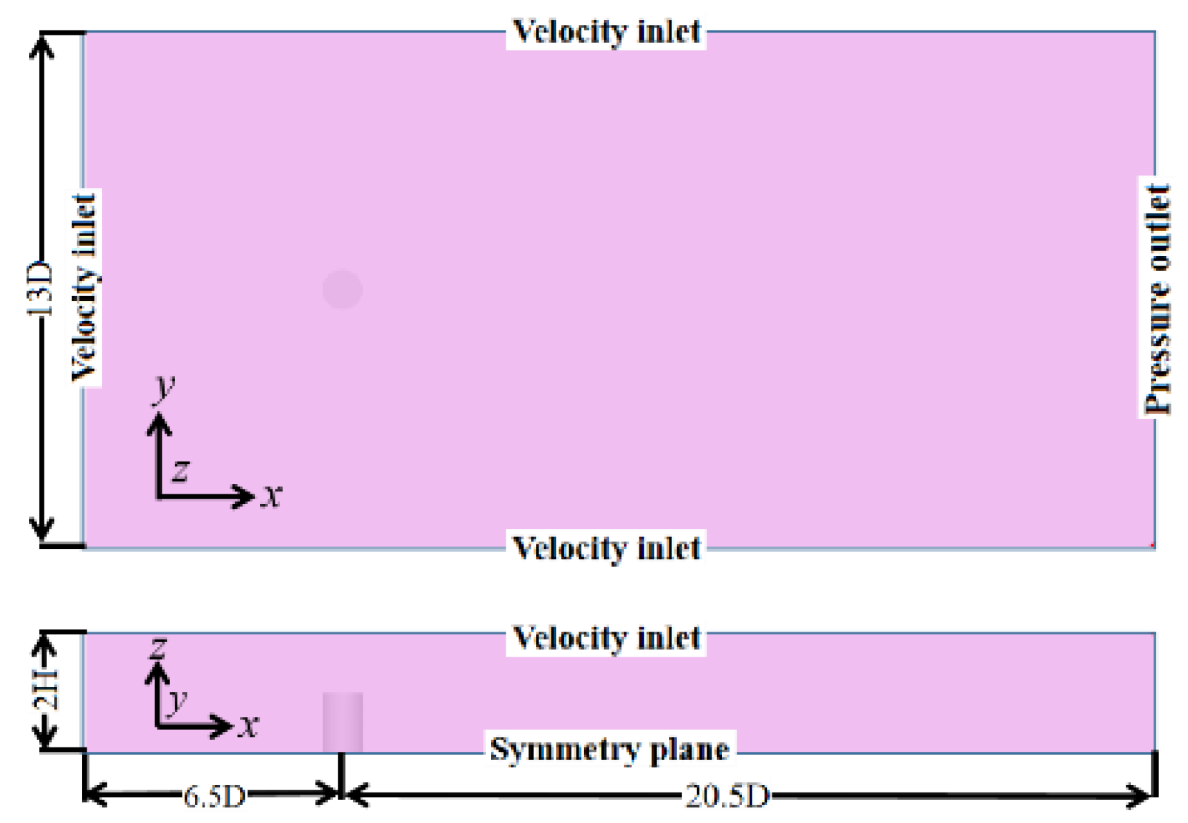
In the numerical simulation, the diameter of the cylinder was 0.65 m, and the length-to-diameter ratio was 1.5. The dimensions of the computational domain and boundary conditions are shown in Figure 1. As shown in the figure, the domain length, width, and height are 27D, 13D, and 2H, respectively. The boundary conditions at the inlet, sides, and top of the domain were set as the velocity inlet, outlet to the pressure outlet, and the bottom surface to the symmetry plane. The time step was obtained from [24], and the dimensionless time step was 0.0005. In the process of meshing, the Y+ value is 0.7, the number of boundary layers is 16, the mesh thickness extension is 1.2, the mesh plus thin ratio is 1.1, and the total number of cells is 3,244,056.
Table 1 lists the results of the drag coefficients with the Strouhal numbers for the experimental results and those obtained in this study. Figure 2a compares the mean flow velocity distribution in the centerline of the Z = h/2 cross-section. Figure 2b shows a comparison of the Z = h/2 circumferential pressure coefficients. The comparison indicates that the numerical simulation results were in good agreement with those in the literature; thus, the calculations were highly accurate.
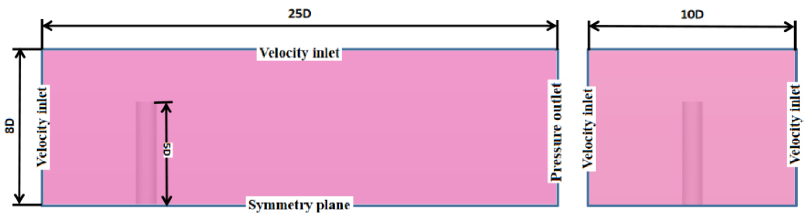
This article uses STAR-CCM+ for grid partitioning and numerical calculations, using a large-eddy simulation model. The numerical simulation was performed with a cylinder diameter of 0.096 m, an end-disk diameter of 2D, an end-disk thickness of 1/10D, and a cylinder height of 5D. The computational domain is shown in Figure 3. The boundary conditions were carefully defined to satisfy the physical results. Moreover, the inlet, upper, and both sides of the computational domain were set to the velocity inlet. The outlet was set to the pressure outlet, the bottom boundary and bottom surface of the cylinder were set to the symmetry plane, and the rest of the cylinder was set to the wall surface. The boundary conditions of the cylinder with an end disk were identical to those of the cylinder. The incoming flow speed was set to 0.5 m/s.
The calculation time step was determined based on the mesh feature size and rotational speed. For the periodic flow, the value of 500 data points per cycle was more accurate. The final dimensionless time step for the static cylinder disturbance was set to 0.008, which satisfied the condition CFL < 1 (Courant number). Additionally, the dimensionless time step was increased or decreased by 0.002 to test the change in the mean drag coefficient. The number of cells used for the calculation is 5.79 × 10⁶. As shown in Table 2, the variation value of the resistance coefficient with the time step is less than 0.6%, and the sensitivity of the resistance coefficient is relatively small within this dimensionless time step range. By combining the above conditions, the dimensionless time step was set to 0.008. The time step for the rotating cylinder was set as in the literature: CFL < 0.5 to satisfy the time required to rotate the cylinder by 1° [26] with 500 data points per cycle. The time step was the same as that of the normal cylinder in the calculation of the cylinder with an end disk.
In the analysis of the mesh uncertainty, the mesh refinement ratio is set to 1.1, the Y+ is 0.7, the number of boundary layers is 16, and the thickness elongation of the boundary layer is 1.2. Based on the same mesh topology, the number of cells is changed by adjusting the basic parameters of the non-boundary layer meshes. The number of cells is shown in Table 3. The drag coefficient calculations for n = 1 were performed based on mesh 1, mesh 2, and mesh 3. The obtained data are given in Table 3.
The numerical uncertainty USN includes the following types of computational errors: iterations (), mesh size (), time step size (), and others (). The expression for numerical uncertainty is:
The uncertainty study of the mesh is performed by keeping the time step and other parameters unchanged. In this case, Equation (18) can be expressed as:
Table 4 shows the data for the mesh number uncertainty validation. The mesh uncertainty analysis refers to the relevant guidelines and recommendations for numerical uncertainty studies in ITTC 75-03-01-01, 2021. It can be seen that the mesh convergence rate RG < 1. This indicates that the mesh topological form converges well.
Half of the difference between the maximum and minimum values at the moment of convergence of the drag is the uncertainty UI of the number of iterations. The uncertainty of total drag iteration number UI = 0.04. This is a small amount compared to the mesh size uncertainty UG in Table 4. Therefore, the mesh uncertainty study in this paper only considers the effect of the mesh size.
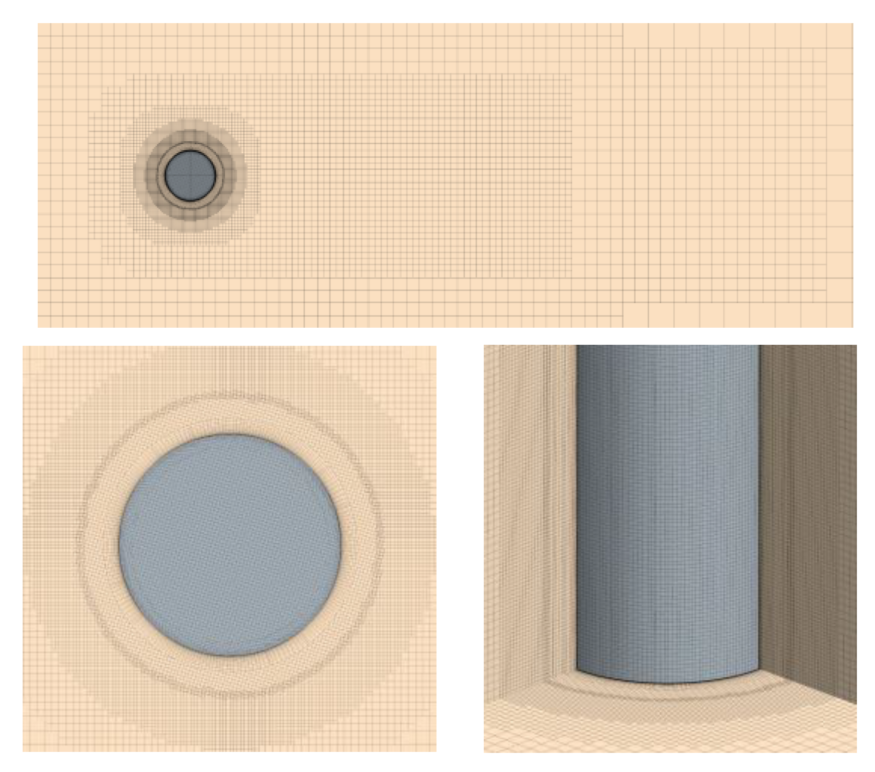
The final calculated numerical uncertainty USN of the total ship resistance is 3.492% CD. This indicates that this grid topology form converges well, and subsequent model-scale resistance calculations will be performed based on grid 2. Figure 4 shows the detailed grid division. An unstructured hexahedral mesh is used for the overlapping regions. The boundary layer of the cylinder is divided using a prismatic layer mesh.
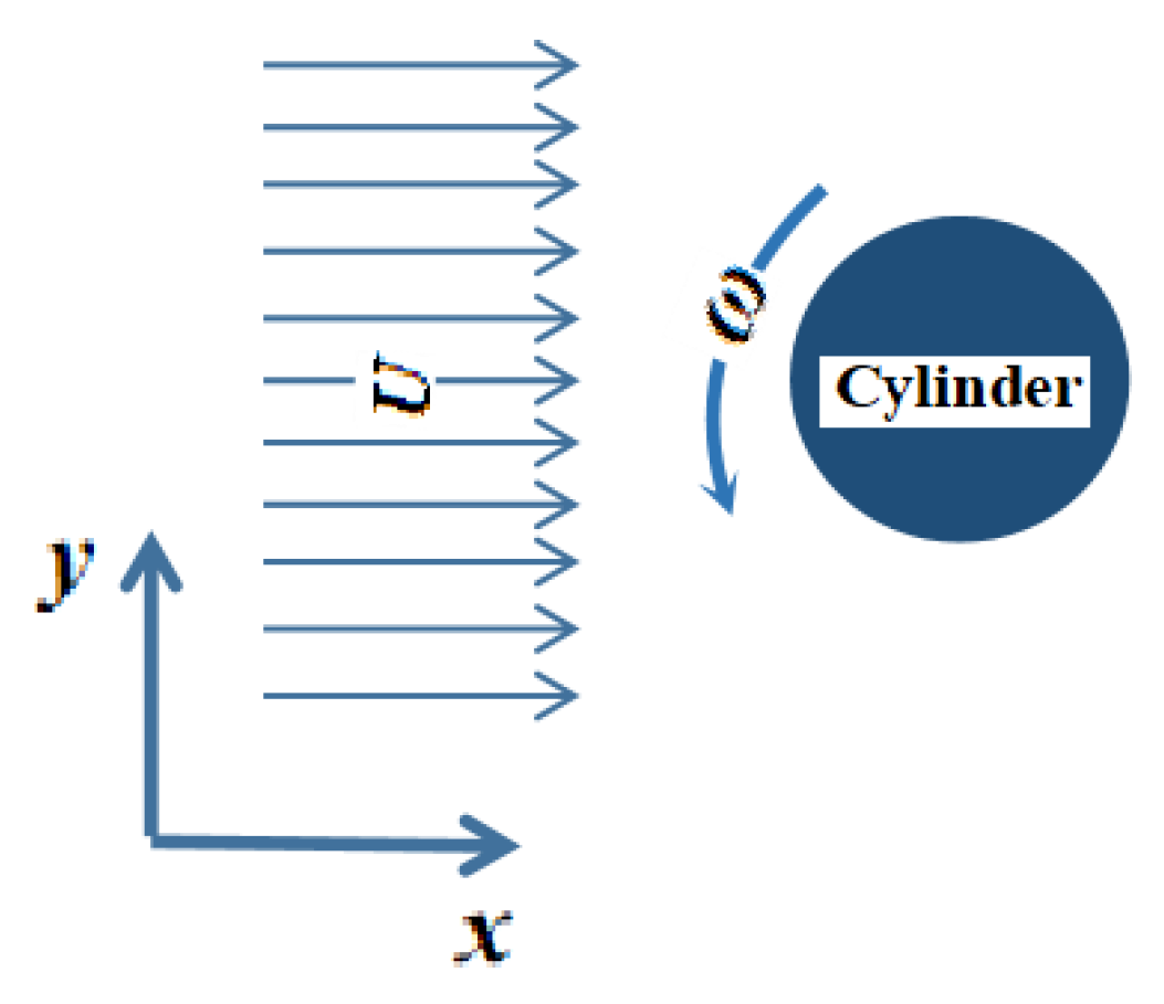
Furthermore, a speed ratio of n = 0–5 (interval of 0.5) was selected. A schematic of the cylinder rotation is shown in Figure 5. The counterclockwise rotation of the cylinder was assumed as the positive direction; U is inflow velocity, and ω is angular velocity.
4. Analysis of the Numerical Results
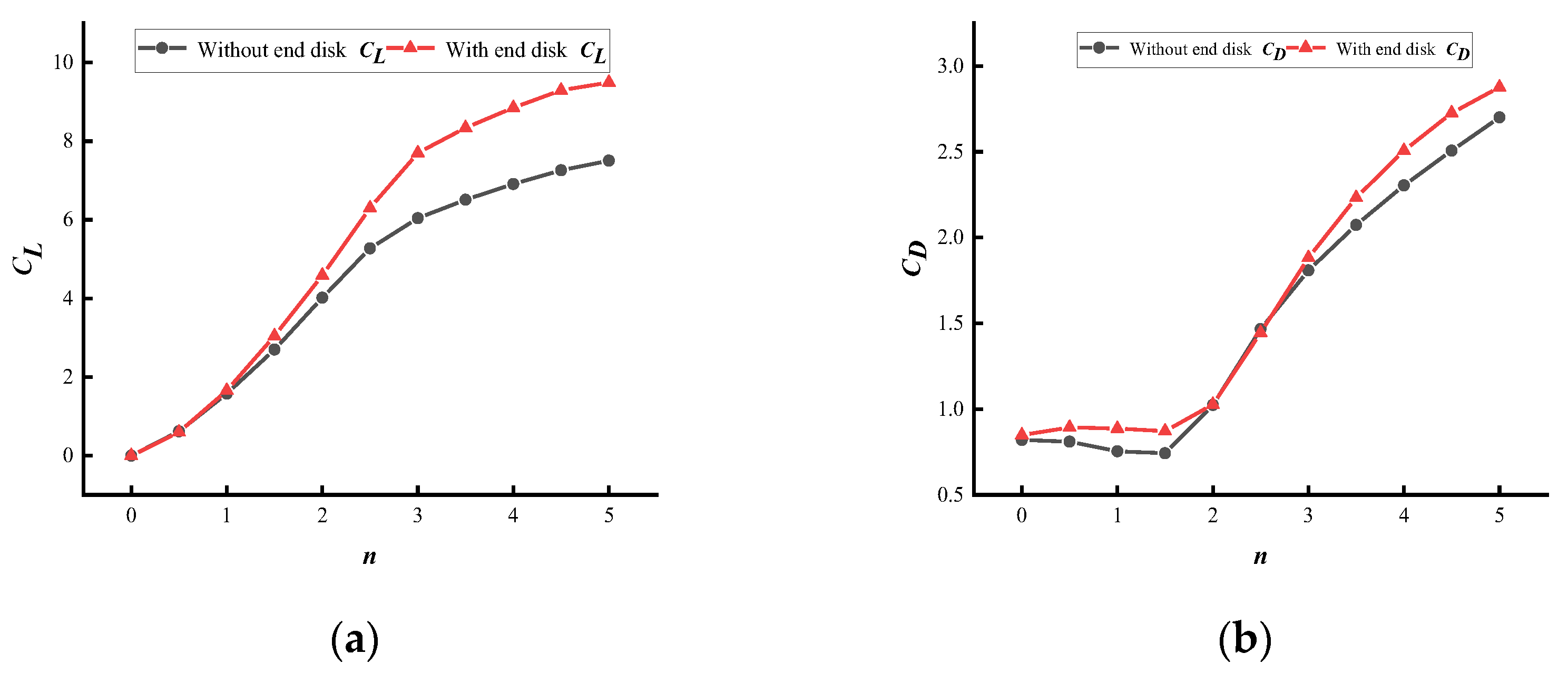
Figure 6a shows a comparison of the lift coefficients with and without the end disk. Figure 6b shows a comparison of the drag coefficients with and without the end disk. The general trend of the cylinder lift coefficient is shown in Figure 6a; the coefficient increases gradually with an increasing speed ratio. At n ≤ 2, the lift coefficient is strongly affected by the speed ratio; at n > 2.5, the lift coefficient is less affected by the speed ratio. At n = 5, the lift coefficient does not reach the Prandtl limit. Note that the increase in the end disk significantly increases the lift coefficient and lift coefficient growth rate. Figure 6b shows that the cylinder drag coefficient curve first decreases and then increases. The decrease in drag coefficient at n ≤ 1.5 might be due to the recirculation zone at the rear of the cylinder. Moreover, the effect of the end disk on the drag coefficient was not significant, and the drag coefficients for cylinders with increased end disks were slightly greater than those for cylinders without end disks at smaller and larger speed ratios. The variation pattern of the drag coefficient when the speed ratio is less than 2 is the same as the pattern of Swanson’s experimental value [27].
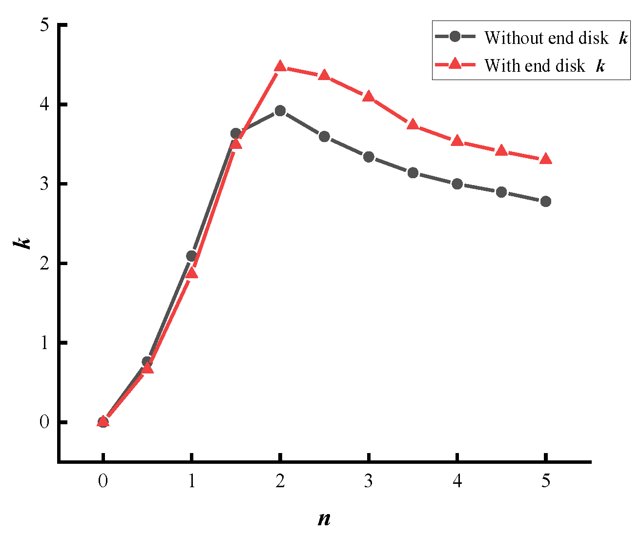
The lift–drag ratio is a direct indication of the relative magnitudes of CL and CD. Figure 7 shows a comparison of the k values for a cylinder with and without the end disk. The graph shows that the value of k increases with n for n < 2 and decreases with n for n > 2. Note that at n > 2, the lift-to-resistance ratio of a cylinder with an end disk is greater than that of a cylinder without an end disk. In the critical zone, the lift-to-resistance ratio of the cylinder peaks at a speed ratio of approximately 2 when the aerodynamic efficiency is at its best.
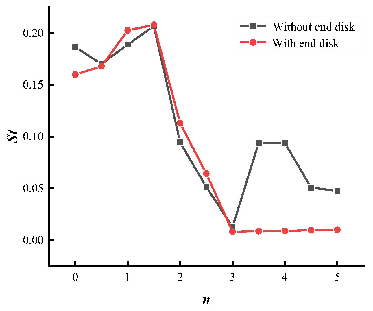
Figure 8 shows a comparison of the St values of the cylinder with and without the end disk. The vortex shedding frequency increases with increasing speed ratio at 0 < n < 1.5, as shown in the figure. A similar pattern phenomenon was also found by Chew et al. [28] and Lam and Lam [29]. As the speed ratio increased, the St value decreased significantly at speed ratios n > 2, indicating that vortex shedding was suppressed at this time. The vortex shedding frequency and St number decreased sharply at 2 < n < 5, and the variation pattern became less evident. Moreover, in the range 2 < n < 5, the effect of the end disk was minor.
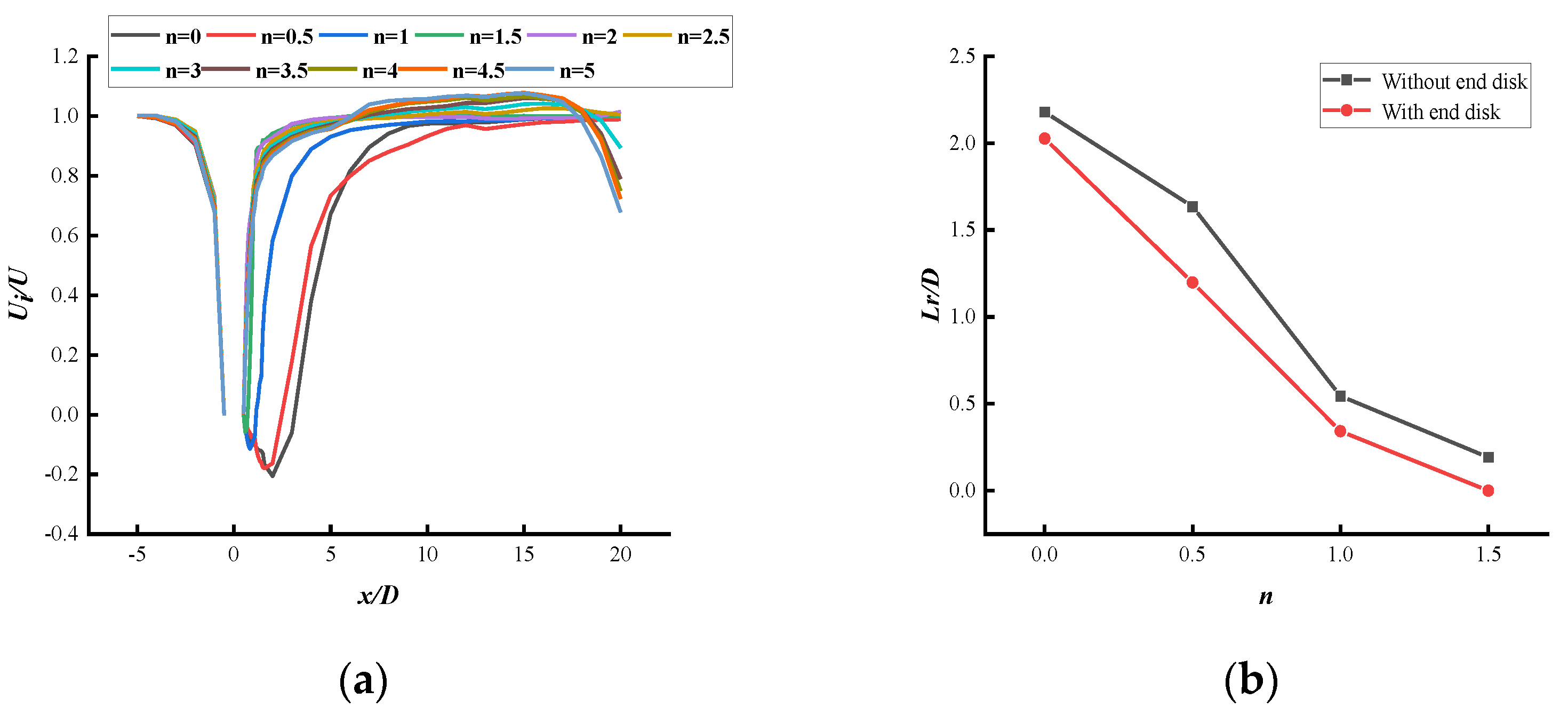
Figure 9a shows the velocity distribution along the centerline of the cylinder in the Z = h/2 section. Moreover, Figure 9b shows a comparison of the return-flow zone length with and without the end disk. The figure indicates that at speed ratios 0 ≤ n ≤ 2, a negative velocity zone called the recirculation zone appears in the near wake of the cylinder. The length of the recirculation zone decreases as the speed ratio increases. At n = 2, the recirculation zone disappears completely. The length of the recirculation zone decreased when adding the end disk, and the zone disappeared at n = 1.5. The addition of the end disk eliminates the recirculation zone.
Figure 10 shows a comparison of the streamwise velocity distribution with and without the end disk Z = h/2 section at 0.58D, 1.06D, 1.54D, and 2.02D from the x-axis (owing to the same phenomenon, only n = 0, 1, 2, and 5 were selected for the study in this figure). Note that at n = 0, a significant decrease in the mean streamwise velocity inside the recirculation zone occurs. This was caused by the obstructive effect of the cylinder on the flow field. The flow velocity profile Ui at X/D = 0.58 in the wakefield shows a “U” shape with the y-coordinate. Furthermore, the flow develops into a “V” shape downstream as the distance increases. As the rotation of the cylinder changed the form of the velocity distribution, it reached a steady state when n = 2 at each position. At 2 ≤ n ≤ 5, the flow velocity distribution does not change and is symmetrical about a line parallel to the x-axis. The end disk does not significantly affect the streamwise velocity distribution.
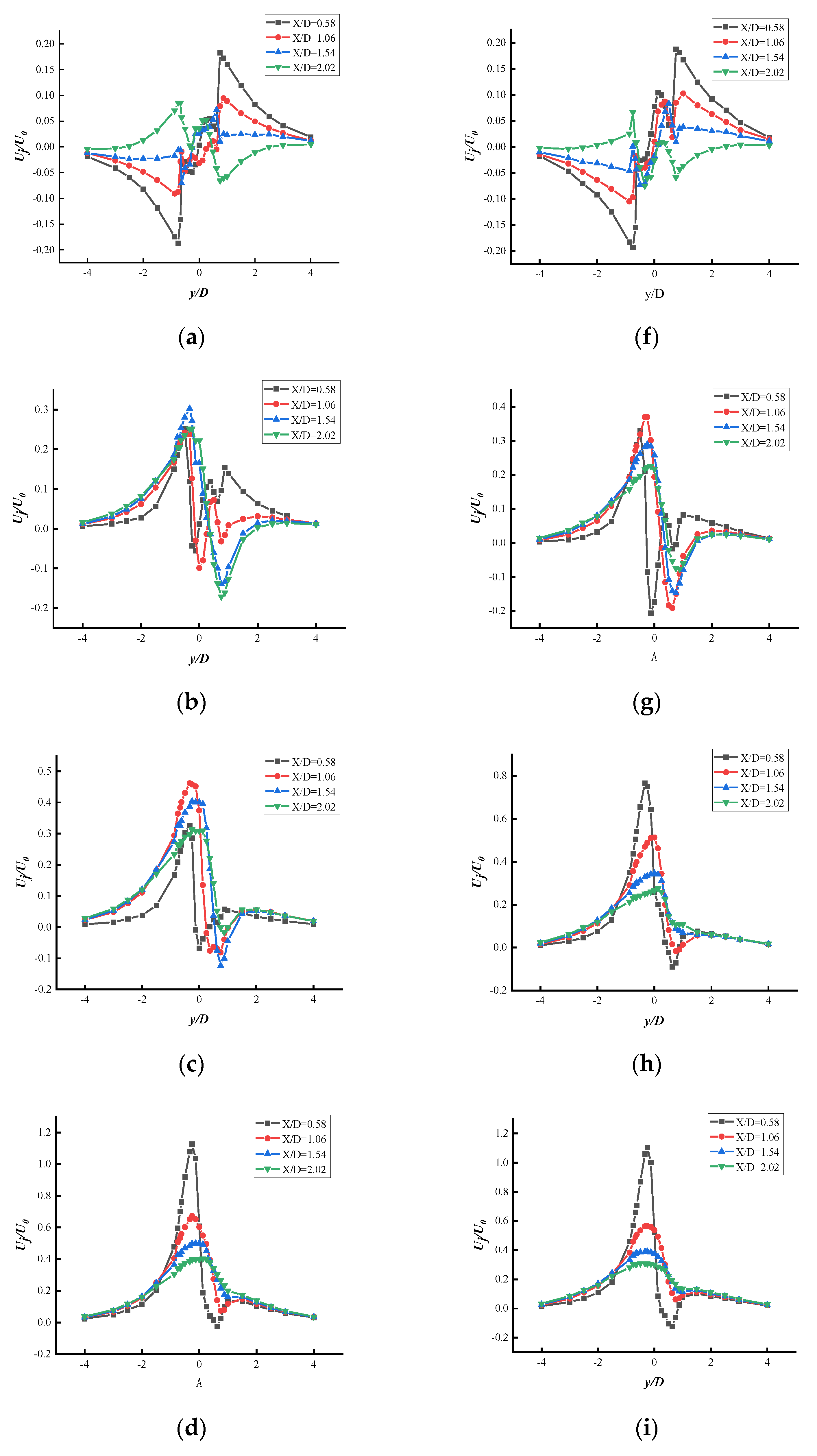
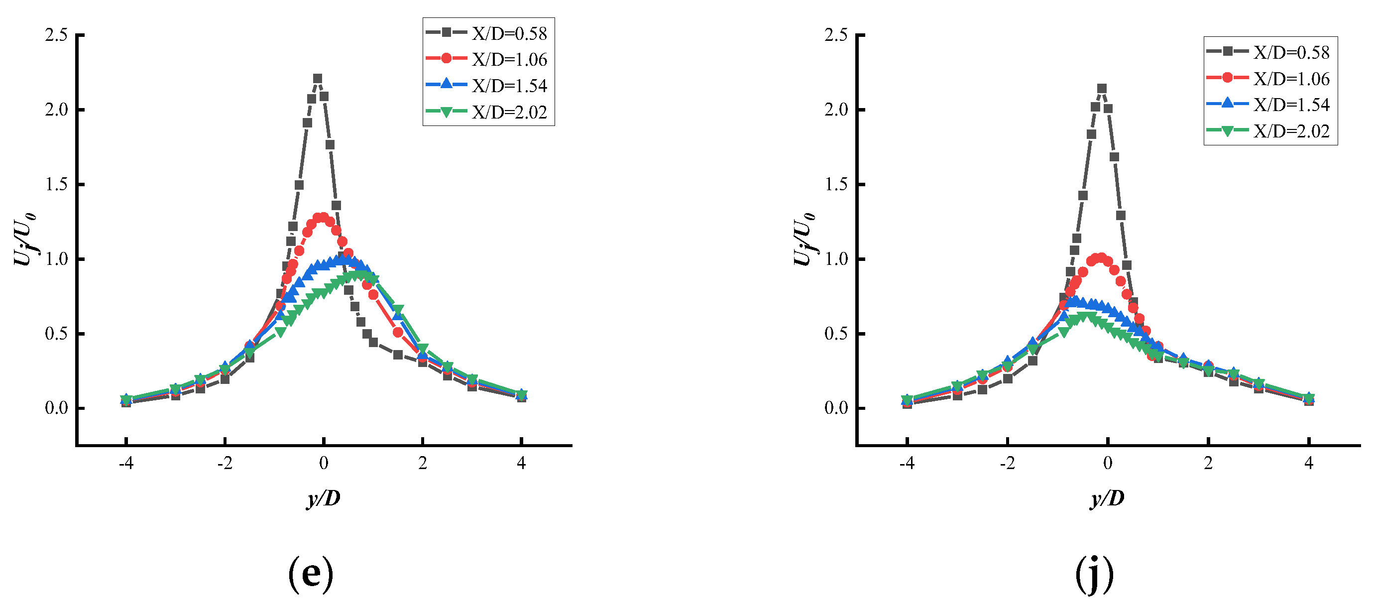
Figure 11 shows a comparison of the flow velocities with and without the end disk Z = h/2 section at 0.58D, 1.06D, 1.54D, and 2.02D from the x-axis (owing to the same phenomenon, only n = 0, 1, 1.5, 2, and 5 were selected for this study). The graph shows that at n = 0, the lateral velocity distribution exhibits an antisymmetric form. The distribution of the crosswise velocities varies as the cylinder rotates, with the distribution of crosswise velocities becoming disturbed at 0 < n < 2 and stable at n = 2, with an inverted “V” shape. At higher speed ratios, the crosswise velocity distribution of the cylinder did not change. The increase in the end disk shifts forward the stabilization period of the crosswise velocity distribution, already stabilized at n = 1.5.
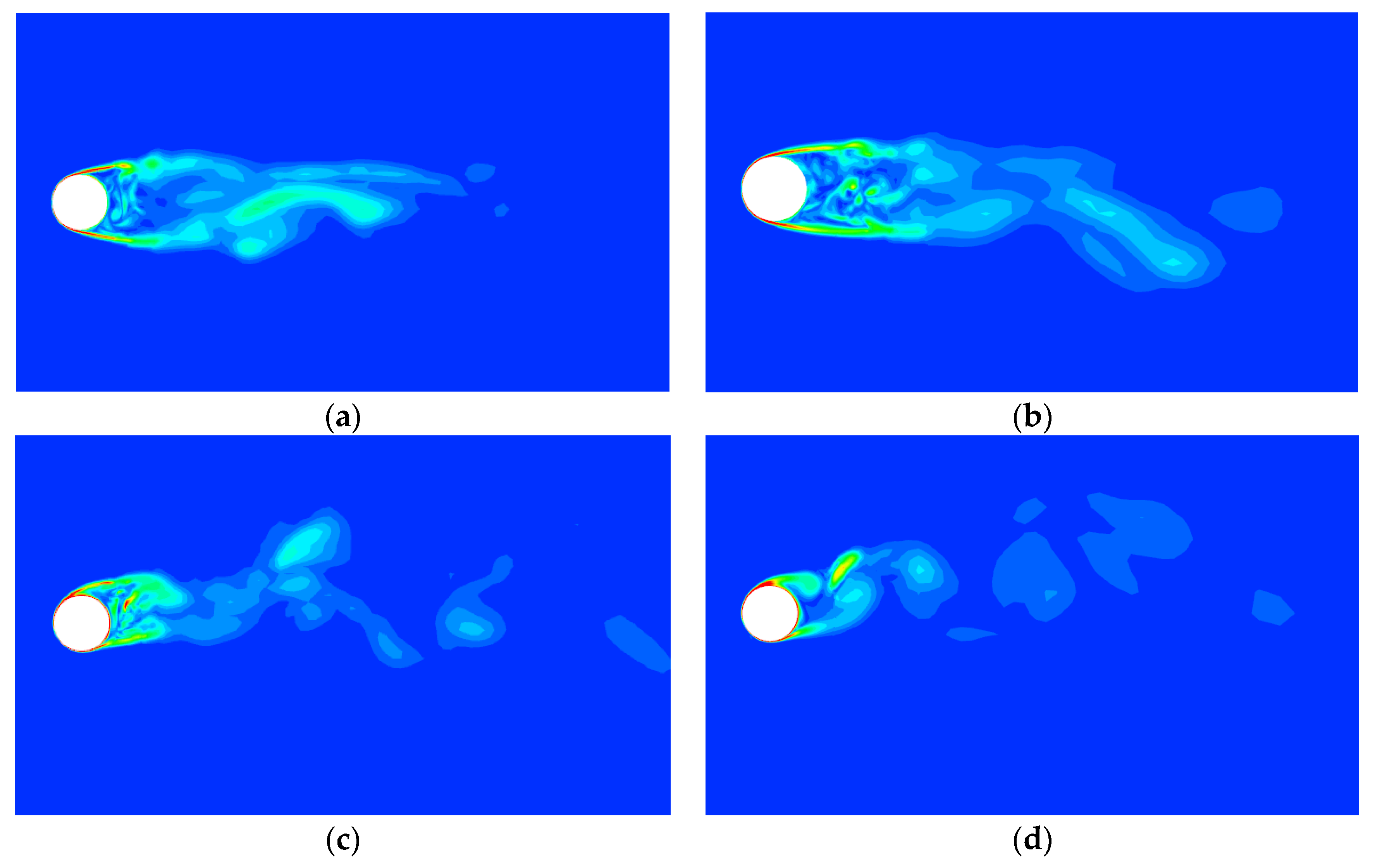
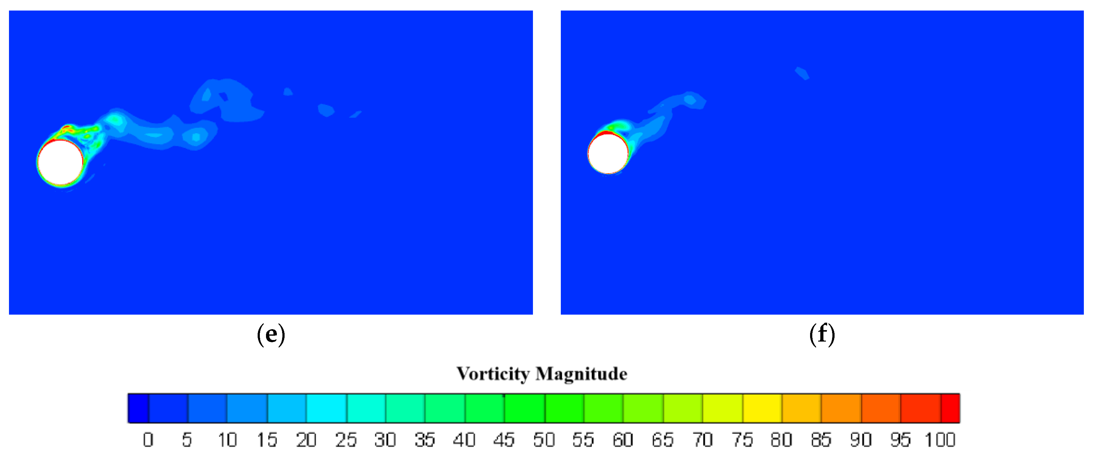
Figure 12 shows a comparison of the vortex distribution with and without the end plate Z = h/2 cross section (owing to the same phenomena, only n = 0, 1, and 2 were selected for the study in this figure). The results show that the LES is more finely resolved for small-scale vortices with a turbulent structure behind the cylinder. At n = 0, the vortex shedding on both sides of the cylinder is symmetrical, and the turbulent structure behind it is complex. As the cylinder rotated, the shear layer and rear vortex structure began to move toward the rotation. At n ≥ 2, the rear vortex shedding is constrained, and the wake region width decreases as the speed ratio increases.
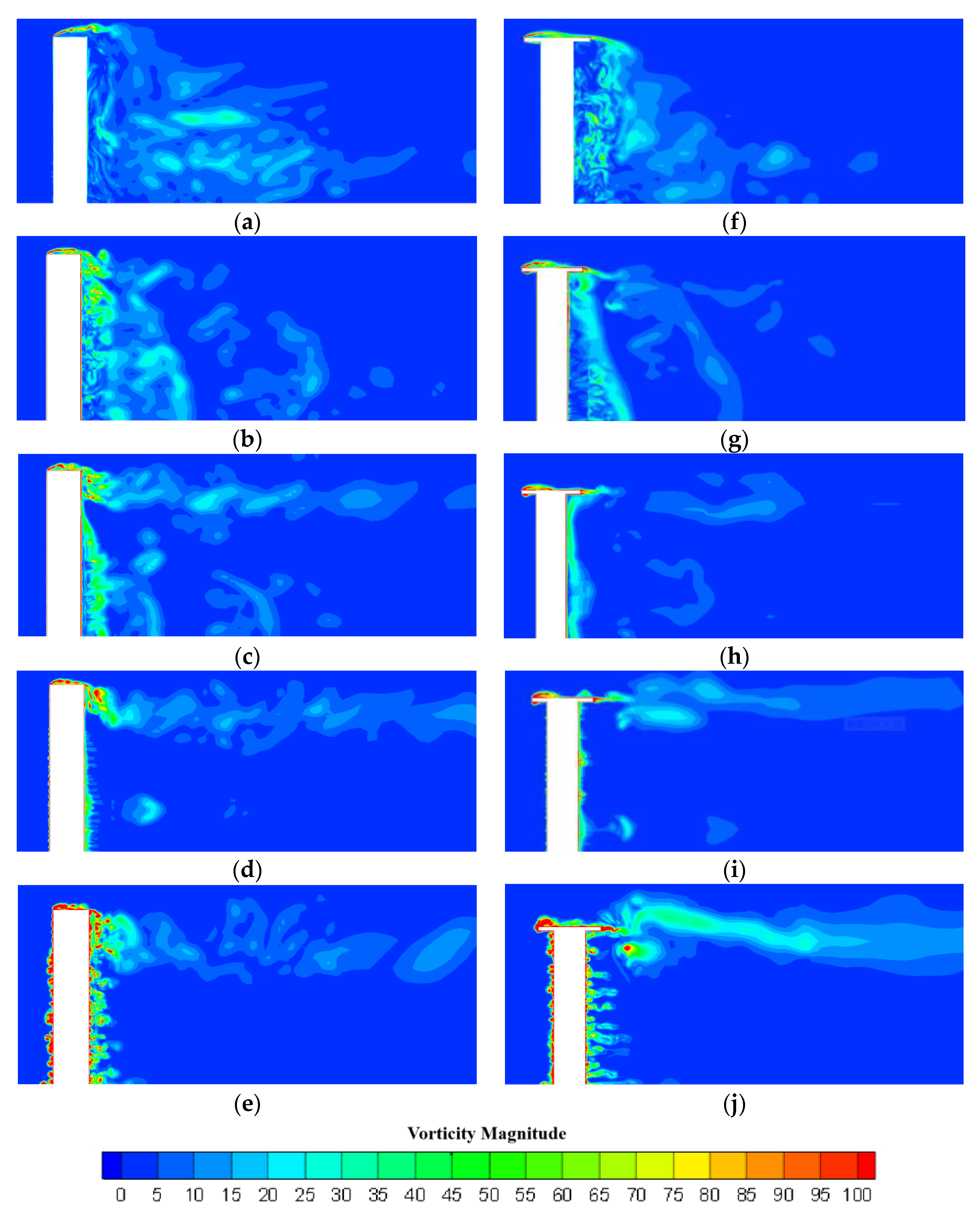
Figure 13 shows a comparison of the vortex distribution with and without the end plate at section y = 0 (owing to the same phenomena, only n = 0, 1, 1.5, 2, and 5 were selected for this study). At n = 0, the incoming stream passed through the front end of the cylinder, creating a vortex structure that curled upward. The vortex structure then develops downwards at the back end, and the back of the cylinder generates a large and complex vortex downstream, forming a downwash vortex and complex flow at the back end of the free end of the cylinder. At n = 1.5, the tip vortices start appearing behind the cylinder, and at n > 2, the vortex structure downstream of the cylinder has mostly disappeared. Moreover, only the tip vortices falling off at the free end of the cylinder develop downstream. As the speed ratio increased, the vortex structure formed at the free end became more intense and complex when the distribution of the tip vortices was approximately below the horizontal position of the free end. The diagram shows a small vortex structure along the spreading direction of the cylindrical wall at n = 2. As the speed ratio increased, the fine vortex structure on the cylindrical wall surface became more evident. The addition of the end disk revealed that the rear vortex structure was not as violent as that of the cylinder, with the fluid swirling at the leading edge of the endplate. The fluid that did not swirl back continues to flow forward. After leaving the end disk, the fluid splits into two parts: one part flows toward the surface of the cylinder, forming a tip vortex, and the other part develops backward in a trajectory that is no longer straight but rather biased downwards. At n = 1.5, the free end of the cylinder with the end disk did not produce tip vortices, as in a normal cylinder. At n = 2, tip vortices appear. Finally, at n ≥ 2, the vortex shedding from the cylinder is suppressed. However, the tip vortex is still generated and intensifies with an increasing speed ratio.
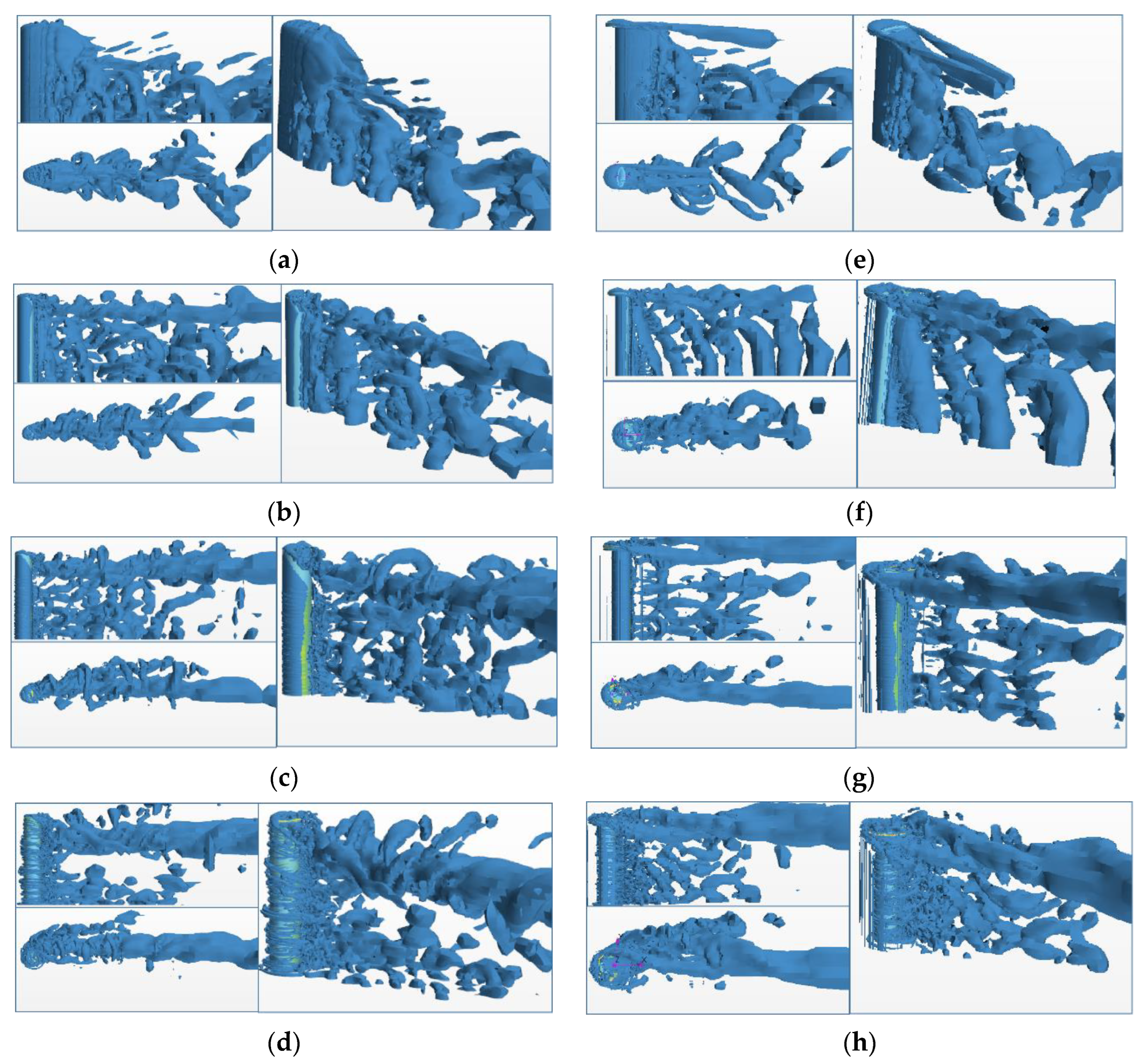
Figure 14 presents a comparison of the three-dimensional vortex structure with and without the end disk. At n = 0, the flow field of the cylinder is confined to a small area with alternating vortex shedding at the rear of the cylinder. The vortex cross-section in the side view of the cylinder was approximately “triangular”, with the vortex structure developing downwards at the cylindrical wake to form a downwash vortex. At n = 1, the vortex cross-section in the side view of the cylinder becomes “rectangular”. The tip vortex started at the free end of the cylinder and developed downstream. As the speed ratio increased, the downwash vortex became less evident, and the vortex structure shifted toward the cylinder rotation. As the speed ratio increases at n ≥ 2, the vortex shedding behind the cylinder is suppressed; however, the tip vortex formed at the free end does not disappear, and various small broken vortex structures are formed behind the cylinder. The addition of the end disk revealed that, at n = 0, two parallel vortex structures similar to the horseshoe vortex were formed at the end disk. At n = 1, the parallel vortex structures at the end plates began to intersect, and the effect of the free-end downwash vortex on the vortex structure in the middle of the cylinder decreased. The overall vortex structure was similar to that of an infinitely long cylinder.
5. Conclusions
This study evaluated the aerodynamic characteristics (aerodynamic loads and flow field characteristics) of a three-dimensional rotating cylinder using a large-eddy simulation method. The effect of the end plates on the aerodynamic characteristics of the cylinder was investigated, and the following conclusions were drawn:
- The cylinder lift coefficient increases with the speed ratio; however, at n = 5, the CL value does not reach the Prandtl limit. The speed ratio strongly affected the lift coefficient when the speed was low (n < 2). At higher speed ratios (n > 2), the lift coefficient was less affected by the speed ratio. The maximum effect of the end plates on the lift coefficient was approximately 28%. For example, when the speed ratio is 3, the lift coefficient is increased by 27%, the drag coefficient is increased by 24%, and the lift-to-drag ratio is increased by 23% after adding the end plate. The growth rate of the lift coefficient was higher for a cylinder with an end disk than that without an end disk. The drag coefficient of the cylinder decreased and then increased as the speed ratio varied. The drag coefficient with the addition of an end disk was slightly greater than that of a cylinder without an end disk. The lift-to-resistance ratio of the cylinder increased and then decreased as the speed ratio changed. In particular, the lift-to-resistance ratio of the cylinder with an end disk was significantly higher than that of the cylinder without an end disk. The lift-to-resistance ratio of both cylinders reached its maximum at a speed ratio of n = 2. Thus, in engineering applications, the aerodynamic performance of a cylinder is significantly improved by adding end plates, and the theoretically optimal speed ratio is n = 2.
- A recirculation zone existed at the rear of the cylinder. The length of the recirculation zone decreases as the speed ratio increases. At n = 2, the cylindrical recirculation zone disappeared completely. The presence of an end disk reduced the length of the recirculation zone and caused the zone to disappear when the end disk was added. At n = 1.5, the recirculation zone with the cylindrical endplate completely disappeared.
- The mean streamwise velocity develops from a “U” shape to a “V” shape as the flow field develops at n = 0. As the speed ratio increases (n = 2), the velocity distribution stabilizes in an “antisymmetric” form. Moreover, the average crosswise velocity distribution stabilizes at n = 2, with an inverted “V” shape. With the addition of the end disk, the crosswise velocity distribution stabilization period occurred earlier, reaching stability at n = 1.5.
- Considering the three-dimensional vortex structure, the vortex shedding was suppressed at higher speed ratios (n > 2) for the cylinder. However, the tip vortex shedding continued. The end disk has a slight hindering effect on the development of the downwash vortex and a strong influence on the tip vortex development. The tip vortex shedding of the cylinder was slightly downwashed. However, the tip vortex of the cylinder with the end plates changed from the initial “horseshoe vortex” on both sides of the parallel end plates to a vortex structure with crossed sides as the speed ratio changed.
Author Contributions
Conceptualization, D.Z. and Y.Z.; methodology, Y.Z.; software, Y.Z.; validation, Y.Z., X.Z. (Xianghai Zhong) and M.B.; formal analysis, Y.Z. and M.B; investigation, Y.Z.; resources, D.Z.; data curation, X.Z. (Xin Zheng); writing—original draft preparation, Y.Z.; writing—review and editing, Y.Z. and S.Z.; visualization, X.Z. (Xianghai Zhong) and S.Z.; supervision, D.Z. and X.Z. (Xin Zheng); project administration, D.Z.; funding acquisition, D.Z. All authors have read and agreed to the published version of the manuscript.
Funding
This study was funded by the National Natural Science Foundation of China, grant number 52071105.
Institutional Review Board Statement
Not applicable.
Informed Consent Statement
Not applicable.
Data Availability Statement
Not applicable.
Conflicts of Interest
The authors declare no conflict of interest.
References
- Karabelas, S.J. Large eddy simulation of high-Reynolds number flow past a rotating cylinder. Int. J. Heat Fluid Flow. 2010, 31, 518–527. [Google Scholar] [CrossRef]
- Aoki, K.; Ito, T. Flow characteristics around a rotating cylinder. Proc. Sch. Eng. Tokai Univ. 2001, 26, 29–34. [Google Scholar]
- Zhang, W.; Bensow, R. Numerical simulation of high-Reynolds number flow around Flettner rotors. In Proceedings of the 14th Numerical Towing Tank Symposium, Southampton, UK, 22 October 2011. [Google Scholar]
- Karabelas, S.J.; Koumroglou, B.C.; Argyropoulos, C.D.; Markatos, N.C. High Reynolds number turbulent flow past a rotating cylinder. Appl. Math. Modell. 2012, 36, 379–398. [Google Scholar] [CrossRef]
- Kruger, J.P.; Everts, M.; Ebrahim, R.; Miles, E.; Sharifpur, M.; Meyer, J.P. Turbulent flow across a rotating cylinder with surface roughness. In Proceedings of the 10th International Conference on Heat Transfer, Fluid Mechanics and Thermodynamics, Orlando, FL, USA, 14–16 July 2014. [Google Scholar]
- Craft, T.J.; Iacovides, H.; Johnson, N.; Launder, B.E. Back to the future: Flettner-Thom rotors for maritime propulsion? In Proceedings of the Eventh International Symposium on Turbulence, Heat and Mass Transfer, Palermo, Italy, 24–27 September 2012; pp. 1104–1113. [Google Scholar]
- Da-Qing, L.; Leer-Andersen, M.; Allenström, B. Performance and vortex formation of Flettner rotors at high Reynolds numbers. In Proceedings of the 29th Symposium on Naval Hydrodynamics, Gothenburg, Sweden, 26–31 August 2012. [Google Scholar]
- Badalamenti, C. On the Application of Rotating Cylinders to Micro Air Vehicle; City University London: London, UK, 2010. [Google Scholar]
- De Marco, A.; Mancini, S.; Pensa, C. Preliminary analysis for marine application of Flettner rotors. In Proceedings of the 2nd International Symposium on Naval Architecture and Maritime (INT-NAM’14), Istanbul, Turkey, 23–24 October 2014. [Google Scholar]
- Reid, E.G. Tests of Rotating Cylinders; Technical Report Archive & Image Library, 1924; Available online: http://digital.library.unt.edu/ark:/67531/metadc53882 (accessed on 1 April 2023).
- Thom, A. Effect of Discs on the Air Forces on a Rotating Cylinder; HM Stationery Office: Richmond, UK, 1934. [Google Scholar]
- Rao, A.; Radi, A.; Leontini, J.S.; Thompson, M.C.; Sheridan, J.; Hourigan, K. A review of rotating cylinder wake transitions. J. Fluids Struct. 2015, 53, 2–14. [Google Scholar] [CrossRef]
- Martin-Alcantara, A.; Sanmiguel-Rojas, E.; Fernandez-Feria, R. On the development of lift and drag in a rotating and translating cylinder. J. Fluids Struct. 2015, 54, 868–885. [Google Scholar] [CrossRef]
- Kusaiynov, K.; Tanasheva, N.K.; Turgunov, M.M.; Alibekova, A.R. Analysis of aerodynamic characteristics of rotating porous cylinders. Tech. Phys. 2015, 60, 656–659. [Google Scholar] [CrossRef]
- Benitz, A.M.; Carlson, W.D.; Seyed-Aghazadeh, B.; Modarres-Sadeghi, Y.; Lackner, M.A.; Schmidt, D.P. CFD simulations and experimental measurements of flow past free surface piercing, finite length cylinders with varying aspect ratios. Comput. Fluids 2016, 136, 247–259. [Google Scholar] [CrossRef]
- Zheng, Z.; Lei, J.; Wu, X. Numerical simulation of the negative Magnus effect of a two-dimensional spinning circular cylinder. Flow Turbul. Combust. 2017, 98, 109–130. [Google Scholar] [CrossRef]
- Copuroglu, H.I.; Pesman, E. Analysis of Flettner Rotor ships in beam waves. Ocean Eng. 2018, 150, 352–362. [Google Scholar] [CrossRef]
- Ezadi Yazdi, M.J.; Rad, A.S.; Khoshnevis, A.B. Features of the flow over a rotating circular cylinder at different spin ratios and Reynolds numbers: Experimental and numerical study. Eur. Phys. J. Plus 2019, 134, 189. [Google Scholar] [CrossRef]
- Jiang, H.; Cheng, L. Large-eddy simulation of flow past a circular cylinder for Reynolds numbers 400 to 3900. Phys. Fluids 2021, 33, 034119. [Google Scholar] [CrossRef]
- Xu, Y.; Chen, S. Analysis of flow characteristics around a rotating cylinder. Chin. J. Mech. 2021, 53, 1900–1911. [Google Scholar]
- Ma, W.; Liu, J.; Zhang, X.; Li, Y. Study of Reynolds number effect on the aerodynamic characteristics of rotating cylinders. Vib. Shock 2022, 41, 46–52. [Google Scholar]
- Tang, W.; Chen, W.; Wu, Y.; Chen, S.; Li, X. Numerical simulation study of rotating cylindrical spoiler under different flow conditions. J. Wuhan Univ. Technol. (Transp. Sci. Eng.) 2022, 46, 247–253. [Google Scholar]
- Ciofalo, M. Large eddy simulation. Thermofluid Dyn. Turbul. Flows 2021, 47–63. [Google Scholar]
- Luo, D.H.; Yan, C.; Liu, H.K.; Zhao, R. Comparative assessment of PANS and DES for simulation of flow past a circular cylinder. J. Wind. Eng. Ind. Aerodyn. 2014, 134, 65–77. [Google Scholar] [CrossRef]
- Zhang, H.; Yang, J.M.; Xiao, L.F.; Lu, H.N. Large-eddy simulation of the flow past both finite and infinite circular cylinders at Re = 3900(Article). J. Hydrodyn. 2015, 27, 195–203. [Google Scholar] [CrossRef]
- Van Rijsbergen, M.; Holtrop, J. Investigations on a Pod Open Water Test Setup; MARINE Internal Report; 2004. [Google Scholar]
- Swanson, W.M. The magnus effect: A summary of investigations to date. J. Basic Eng. 1961, 83, 461–470. [Google Scholar] [CrossRef]
- Chew, Y.T.; Cheng, M.; Luo, S.C. A numerical study of flow past a rotating circular cylinder using a hybrid vortex scheme. J. Fluid Mech. 1995, 299, 35–71. [Google Scholar] [CrossRef]
- Lam, K.M. Vortex shedding flow behind a slowly rotating circular cylinder. J. Fluids Struct. 2009, 25, 245–262. [Google Scholar] [CrossRef]
Figure 1.
Calculation of domain dimensions and boundary conditions.

Figure 2.
(a) Z = h/2 interface flow velocity distribution and the experiments [17]; (b) Z = h/2 circumferential pressure coefficient distribution and the experiments.
Figure 2.
(a) Z = h/2 interface flow velocity distribution and the experiments [17]; (b) Z = h/2 circumferential pressure coefficient distribution and the experiments.

Figure 3.
Cylinder calculation domain dimensions and boundary conditions.

Figure 4.
Mesh division.

Figure 5.
Schematic diagram of the cylinder rotation.

Figure 6.
(a) Comparison of lift coefficients with and without the end disk; (b) comparison of lift coefficients with and without end disk.
Figure 6.
(a) Comparison of lift coefficients with and without the end disk; (b) comparison of lift coefficients with and without end disk.

Figure 7.
Comparison of lift-to-resistance ratios with and without the end disk at different speed ratios.
Figure 7.
Comparison of lift-to-resistance ratios with and without the end disk at different speed ratios.

Figure 8.
Comparison of St numbers with and without the end disk at different speed ratios.

Figure 9.
(a) Velocity distribution along the centerline of the cylinder Z = h/2 section; (b) comparison of the length of the recirculation zone with and without end disk.
Figure 9.
(a) Velocity distribution along the centerline of the cylinder Z = h/2 section; (b) comparison of the length of the recirculation zone with and without end disk.

Figure 10.
Distribution of the cylinder streamwise velocities at n = 0, 1, 2, and 5 for X/D = 0.58D, 1.06D, 1.54D, and 2.02D; (a–d) are unterminated plates and (e–h) are terminated plates.
Figure 10.
Distribution of the cylinder streamwise velocities at n = 0, 1, 2, and 5 for X/D = 0.58D, 1.06D, 1.54D, and 2.02D; (a–d) are unterminated plates and (e–h) are terminated plates.

Figure 11.
Distribution of cylinder crosswise velocities at X/D = 0.58 D, 1.06 D, 1.54 D, and 2.02 D for n = 0, 1, 1.5, 2, and 5; (a–e) are without the end disk and (f–j) are with the end disk.
Figure 11.
Distribution of cylinder crosswise velocities at X/D = 0.58 D, 1.06 D, 1.54 D, and 2.02 D for n = 0, 1, 1.5, 2, and 5; (a–e) are without the end disk and (f–j) are with the end disk.


Figure 12.
Comparison of the vortex distribution in the Z = h/2 section at n = 0, 1, and 2 (a–c) without the end disk and (d–f) with the end disk.
Figure 12.
Comparison of the vortex distribution in the Z = h/2 section at n = 0, 1, and 2 (a–c) without the end disk and (d–f) with the end disk.


Figure 13.
Comparison of the vortex distribution in section y = 0 for n = 0, 1, 1.5, 2, and 5 (a–e) without the end disk and (f–j) with the end disk.
Figure 13.
Comparison of the vortex distribution in section y = 0 for n = 0, 1, 1.5, 2, and 5 (a–e) without the end disk and (f–j) with the end disk.

Figure 14.
Comparison of 3D vortex structures at n = 0, 1, 2, and 5 (a–d) without the end disk and (e–h) with the end disk.
Figure 14.
Comparison of 3D vortex structures at n = 0, 1, 2, and 5 (a–d) without the end disk and (e–h) with the end disk.


Table 1.
Comparison of the calculation results.
| Re | CD | St | |
|---|---|---|---|
| Research [25] | 3900 | 0.782 | 0.11 |
| Exp3 [12] | 2900 | 0.77 | |
| Results of this study | 3900 | 0.765 | 0.12 |
Table 2.
Sensitivity of the resistance coefficient to time step.
| Dimensionless Time Step Δt’ | CD |
|---|---|
| 0.006 | 0.815364 |
| 0.008 | 0.820818 |
| 0.01 | 0.818724 |
Table 3.
Mesh parameters and calculation results.
| Mesh Number | Number of Cells | Lift Coefficient CL | Drag Coefficient CD |
|---|---|---|---|
| 1 | 3.26 × 10⁶ | 1.556 | 0.734 |
| 2 | 4.35 × 10⁶ | 1.577 | 0.749 |
| 3 | 5.79 × 10⁶ | 1.576 | 0.752 |
| 4 | 7.70 × 10⁶ | 1.573 | 0.755 |
| 5 | 10.2 × 10⁶ | 1.575 | 0.753 |
Table 4.
Mesh number uncertainty verification data sheet.
| RG | UG (CD%) | |
|---|---|---|
| Drag coefficient CD | 0.2 | 3.492 |
Disclaimer/Publisher’s Note: The statements, opinions and data contained in all publications are solely those of the individual author(s) and contributor(s) and not of MDPI and/or the editor(s). MDPI and/or the editor(s) disclaim responsibility for any injury to people or property resulting from any ideas, methods, instructions or products referred to in the content. |
© 2023 by the authors. Licensee MDPI, Basel, Switzerland. This article is an open access article distributed under the terms and conditions of the Creative Commons Attribution (CC BY) license (https://creativecommons.org/licenses/by/4.0/).
Share and Cite
MDPI and ACS Style
Zhao, D.; Zhang, Y.; Bi, M.; Zheng, X.; Zhong, X.; Zhang, S. The Aerodynamic Characteristics of a Rotating Cylinder Based on Large-Eddy Simulations. J. Mar. Sci. Eng. 2023, 11, 1162. https://doi.org/10.3390/jmse11061162
AMA Style
Zhao D, Zhang Y, Bi M, Zheng X, Zhong X, Zhang S. The Aerodynamic Characteristics of a Rotating Cylinder Based on Large-Eddy Simulations. Journal of Marine Science and Engineering. 2023; 11(6):1162. https://doi.org/10.3390/jmse11061162
Chicago/Turabian StyleZhao, Dagang, Yang Zhang, Mingqi Bi, Xin Zheng, Xianghai Zhong, and Shun Zhang. 2023. "The Aerodynamic Characteristics of a Rotating Cylinder Based on Large-Eddy Simulations" Journal of Marine Science and Engineering 11, no. 6: 1162. https://doi.org/10.3390/jmse11061162
Note that from the first issue of 2016, this journal uses article numbers instead of page numbers. See further details here.