Article

Study on the Effect of the Guide Vane Opening on the Band Clearance Sediment Erosion in a Francis Turbine

1
State Key Laboratory of Hydroscience and Engineering, Department of Energy and Power Engineering, Tsinghua University, Beijing 100084, China
2
Tagak Hydropower Plant of Xinjiang Xinhua Hydropower Investment Co., Ltd., Beijing 100068, China
*
Author to whom correspondence should be addressed.
J. Mar. Sci. Eng. 2022, 10(10), 1396; https://doi.org/10.3390/jmse10101396
Submission received: 20 August 2022 / Revised: 20 September 2022 / Accepted: 22 September 2022 / Published: 30 September 2022
(This article belongs to the Section Marine Energy)

Abstract

:
Sediment erosion is a negative phenomenon for the water turbine. The purpose of this paper is to study the effect of the guide vane opening on the particle motion and sediment erosion in the band chamber using the Euler–Lagrangian approach. The software Ansys CFX and Tabakoff erosion model are used to simulate the sediment laden flow in the full flow passage of the hydraulic turbine. The results are in good agreement with the actual erosion character on site. Results show that the guide vane opening has a positive correlation with the flow in the non-clearance channel. The increase of the guide vane opening will increase the erosion of the runner blade head, but the friction wear on the outlet side of the blade surface will decrease. The rotating action of the runner makes the sediment particles in the band chamber rotate rapidly around the center of the runner and constantly collide with the band chamber wall. Under the small opening, the smaller the opening, the easier the leakage of the band clearance occurs. The unsteady flow in the band chamber will disturb the motion trajectory of particles, change the impact angle of particles, and affect the wear in the band chamber. Under different openings, the change law of the erosion in the band clearance is closely related to the change law of clearance leakage.

1. Introduction

The improvement of clean energy utilization rate and the energy utilization method coordinated with the environment are the bottleneck of energy development [1]. In response to this problem, countries around the world attach great importance to the development and utilization of green renewable energy. Hydropower resources are important clean energy [2]. As the most core component in the hydropower plant, the main function of the water turbine is to convert the flow power into mechanical energy through kinetic energy conversion. During the operation of the hydropower station, it is found that the water turbine is extremely susceptible to the influence of the operation mode of the hydropower station, the maintenance period of the equipment, the sediment content, and hardness in the water, etc., resulting in serious wear of the water turbine components, especially the water turbine operating in the sediment laden river [3]. In order to improve the service efficiency and service life of the water turbine of the hydropower station, equipment maintenance personnel need to regularly repair the parts of the water turbine that are prone to wear and tear, so as to ensure the normal, safe, and stable operation of the unit, so as to improve the social and economic benefits of the power station. Therefore, no matter from the perspective of safety or economy, cavitation and wear are urgent problems to be solved in hydropower production [4].
The end clearance of the movable guide vane of the water turbine is seriously worn and damaged due to the friction of hard particles in the sediment-laden water flow, which makes the end clearance of the movable guide vane gradually larger and the water leakage continuously increases, which directly causes the unit output to decrease, the working efficiency of the water turbine to decrease, and the water turbine cannot be put into braking due to the high speed after the movable guide vane is closed during the shutdown process, and also affects the stability of the unit [5]. After 1970, the simplified model of clearance leakage vortex flow was put forward, and the numerical study of clearance leakage vortex flow was paid more and more attention. In order to have a more accurate understanding of the principle of clearance flow, many experts and scholars have done a lot of research on clearance flow and achieved certain results [6]. Zhang Y [7] carried out 3D unsteady flow simulation by using entropy theory as the evaluation standard of energy dissipation to study the influence of reflux clearance (the clearance between the motor rotor and the motor housing) on the energy characteristics of the full tube pump. The calculation results verified by tests show that the backflow clearance will produce additional head loss. Gao Chenhui [8] studied the influence of the band clearance of Francis turbine on the performance of the turbine by numerical simulation. The results show that the turbine efficiency gradually decreases with the increase of the band clearance size. Under the small flow condition, the average velocity in the clearance increases, and the average velocity along the flow direction decreases, which proves that the clearance has throttling effect. Under the condition of large flow rate, when the clearance size of the band increases, the pressure distribution on the back of the runner, the flow pattern of the draft tube, and the pressure distribution of the draft tube also improve [9].
Zhang [10] conducted numerical simulation research on two different guide vane airfoils of a Francis turbine with three clearances of 0 mm, 2 mm, and 4 mm. The results show that when the water flow leaves the clearance in the form of leakage flow, the vortex filament can be seen, and the vortex intensity leaving the clearance increases with the increase of the clearance size. Xianbei H [11] conducted numerical simulation and experimental research on two types of guide vane airfoils of water turbines, mainly exploring the clearance flow between the guide vane end face and the top cover, and the occurrence and development of clearance cavitation. The results of experiment and numerical simulation show that when the water flows through the narrow clearance, cavitation vortex structure and clearance cavitation as a steam film are observed. Guo [12] carried out unsteady numerical calculation on the end clearance of movable guide vane of water turbine in sediment laden flow by using numerical simulation method and obtained the average wear rate distribution of main wear surfaces in different wear stages. Zeise B et al. [13] measured the speed and pressure of the guide vane clearance of 2 mm water turbine and observed and measured the leakage flow. The results show that the clearance flow exists in the form of jet and forms vortex filaments with the main flow, which leads to the uneven flow conditions at the inlet of the runner blade. Tian Shrestha et al. [14] conducted three-dimensional numerical simulation on the flow characteristics of the end clearance of the movable guide vane of the Francis turbine under small flow conditions. The results show that with the increase of the end clearance of the movable guide vane, the flow velocity at the clearance also increases, and the pressure distribution in the single channel becomes uniform [15,16].
Considering the harm of clearance wear to the safe operation of the water turbine unit and the lack of relevant research on the clearance wear of the band at present, this paper adopted the numerical simulation to study the clearance wear of the band under different guide vane openings and explores the particle movement law and clearance wear in the band under different guide vane openings. The research results have important engineering value and academic significance.

2. Study Methods

2.1. Mathematical Model

2.1.1. Governing Equations

In this paper, the Eulerian–Lagrangian method is used to simulate the discrete phase particles in the sediment-laden stream of the water turbine [17,18]. The flow control equation of continuous phase is solved by N-S equation.
( ρ u ) t + · ( ρ u u ) = p + ρ v Δ u ρ · τ + S t
where u is the flow velocity, t is the time, ρ is the fluid density, p is the flow pressure, ν is the kinematic viscosity of the fluid and St is the source term. τ is the Reynolds stress defined as:
τ = τ d + 2 k 3 δ
where τd is the deviatoric Reynolds stress, k is the turbulent kinetic energy, and δ is the Kronecker delta. Based on viscosity (νt) assumption, Equation (2) can be written as:
τ = 2 v t S + 2 k 3 δ
where, S is the train-rate tensor,
S = 1 2 ( u + T u )

2.1.2. Lagrangian Tracking of Particle Motions

In this paper, the solid particles adopt the two-phase particle track model under the Lagrangian system. In the Lagrangian framework, the main force on the particles comes from the velocity difference between the particles and the fluid, which contain gravity, resistance, virtual mass force, pressure gradient force, Basset force, Saffman force, Magnus force, etc. [19,20]. The particle track model is as follows:
m p d u p d t = F D + F B + F G + F V + F P + F X
where t is time, mp is particle mass, up is particle velocity, FD is resistance, FB is Basset force, FG is gravity, FV is virtual mass force, FP is pressure gradient force, and FX is the sum of other external forces considered.

2.1.3. Erosion Model

In this paper, the Tabakoff and Grant erosion model is adopted to predict the internal wear of water turbine, which is widely used in the simulation of the erosion in the Francis Turbine [21,22,23]. The model is calculated based on the angle and velocity at which particles collide with the impeller (that is particle trajectories) [24,25]. The formula is as follows:
E = f ( γ ) ( V p V 1 ) 2 cos 2 γ [ 1 ( 1 V p V 3 s i n γ ) 2 ] + ( V p V 2 s i n γ ) 4
f ( γ ) = [ 1 + k 1 k 12 sin ( γ π / 2 γ 0 ) ] 2
Here γ0 is the angle of maximum erosion. k1 to k4, k12, and γ0 are model constants and depend on the particle/wall material combination.

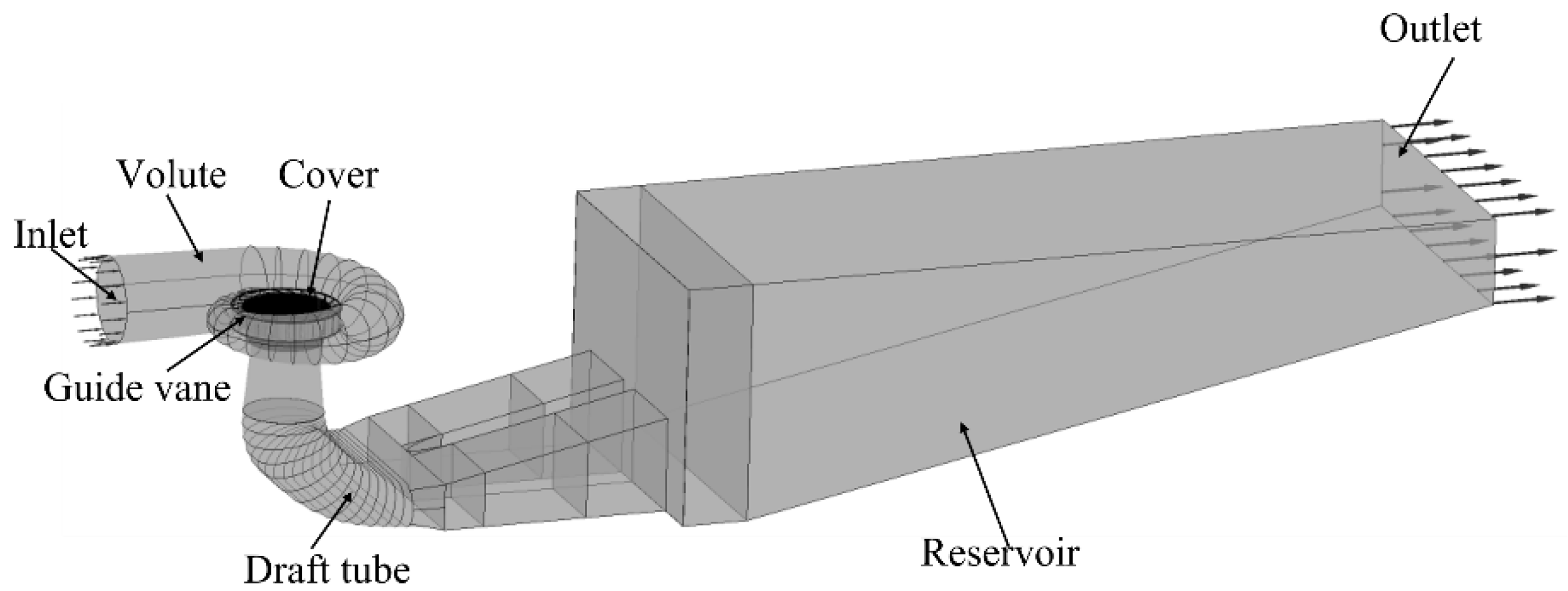
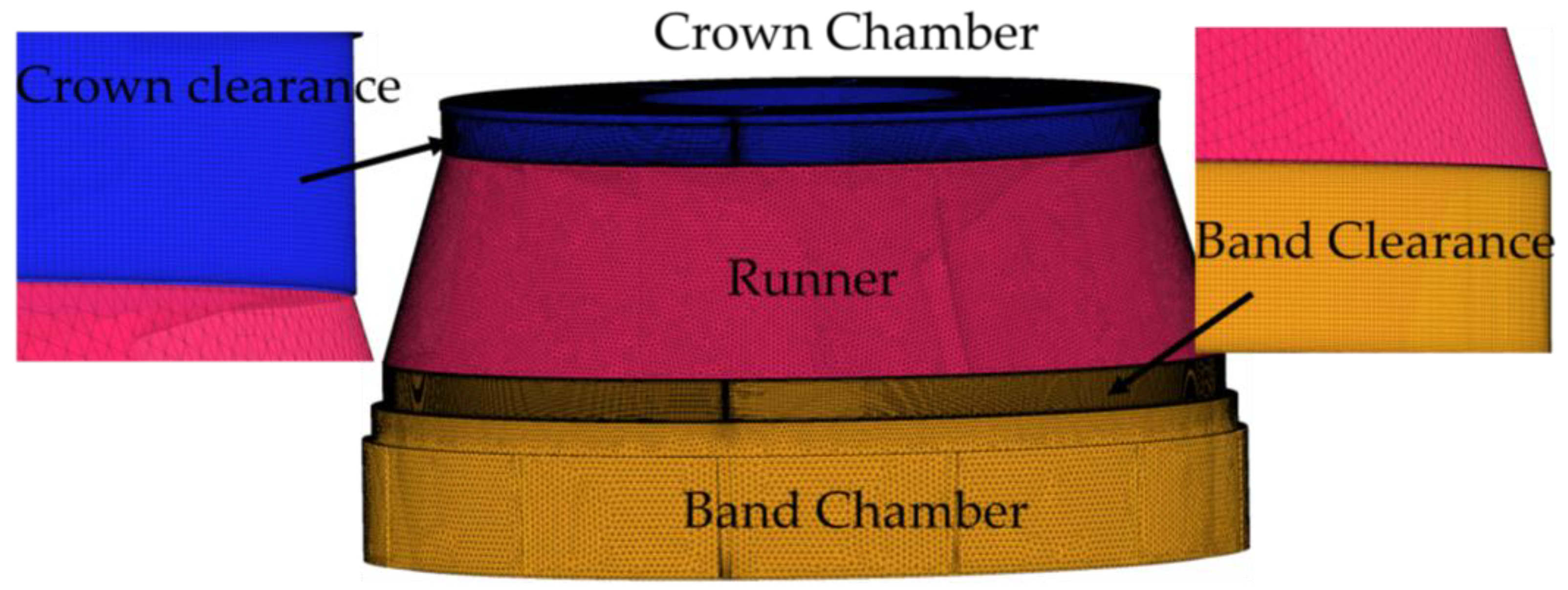
2.2. Simulation Geometry Model

2.2.1. Geometric Model Set Up

A three-dimensional calculation model of the whole flow channel including volute, guide vane, runner, upper crown cavity, band cavity, draft tube, and outlet reservoir is established. The inlet of volute is the inlet of calculation model, and the outlet of the outlet reservoir is the outlet of calculation, as shown in the Figure 1. The maximum thickness of runner blade is 32 mm, the runner diameter is 2.3 m, and the clearance thickness is 1.5 mm. The rotating speed is 300 r/min.
The computational geometric model is meshed, the clearance adopts structured mesh, and other parts adopt hybrid mesh, as shown in the Figure 2. The efficiency of the hydraulic turbine is selected as the criterion for grid independence verification. The software CFX is used to calculate and predict the operating efficiency of the unit when the guide vane opening is 20° under different grid numbers, as shown in Figure 3. Figure 3 clearly shows the relationship between turbine efficiency and grid number. When the number of grids increases from 11.2 million to 12.3 million, the absolute increment of turbine efficiency at the optimal operating point is less than 0.01%, so 11.2 million grids are used for numerical calculation.

2.2.2. Parameter Setting in Calculation Model

(1)
Particle parameters
In this paper, the sediment particles define their own sediment attribute parameters according to the hydrological data of Xinjiang Tagake Hydropower Station. The sediment particles are spherical particles with a particle size of 0.02 mm and a particle density of 2300 kg/m3.
(2)
Boundary condition
The inlet boundary was set the total pressure corresponding to the water head of the upstream, the outlet boundary was adopted the static pressure condition related to the water level of downstream. The wall of the unit was adopted the no-slip boundary. The interface between the runner and stationary parts adopts the dynamic static interface.
(3)
Calculation parameters
In the calculation scheme, the particle concentration is 15 kg/m3, the guide vane openings are designed as 10°, 20°, 25°, 30°. The solution adopts the high-precision differential format and square root RMS residual. Difference format, the solution precision is set to 10−5. The turbulence model adopts the SST k-ω model.

3. Results

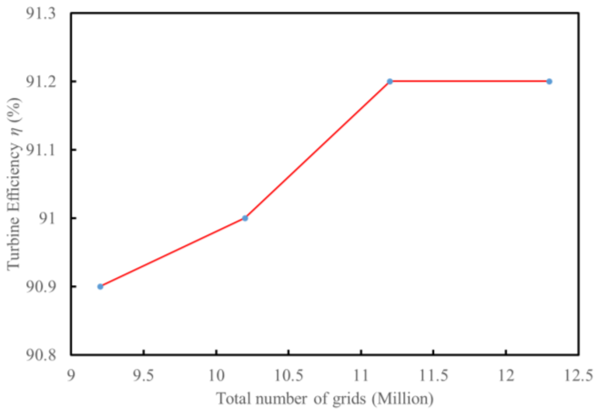
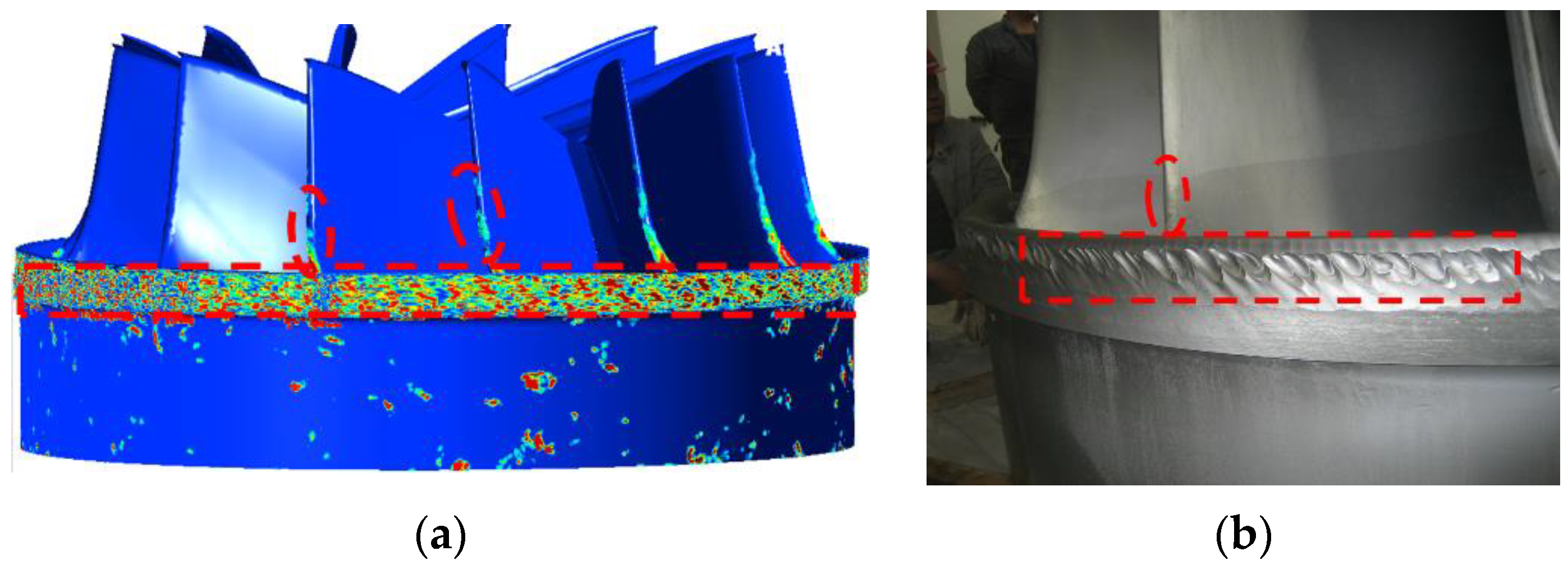
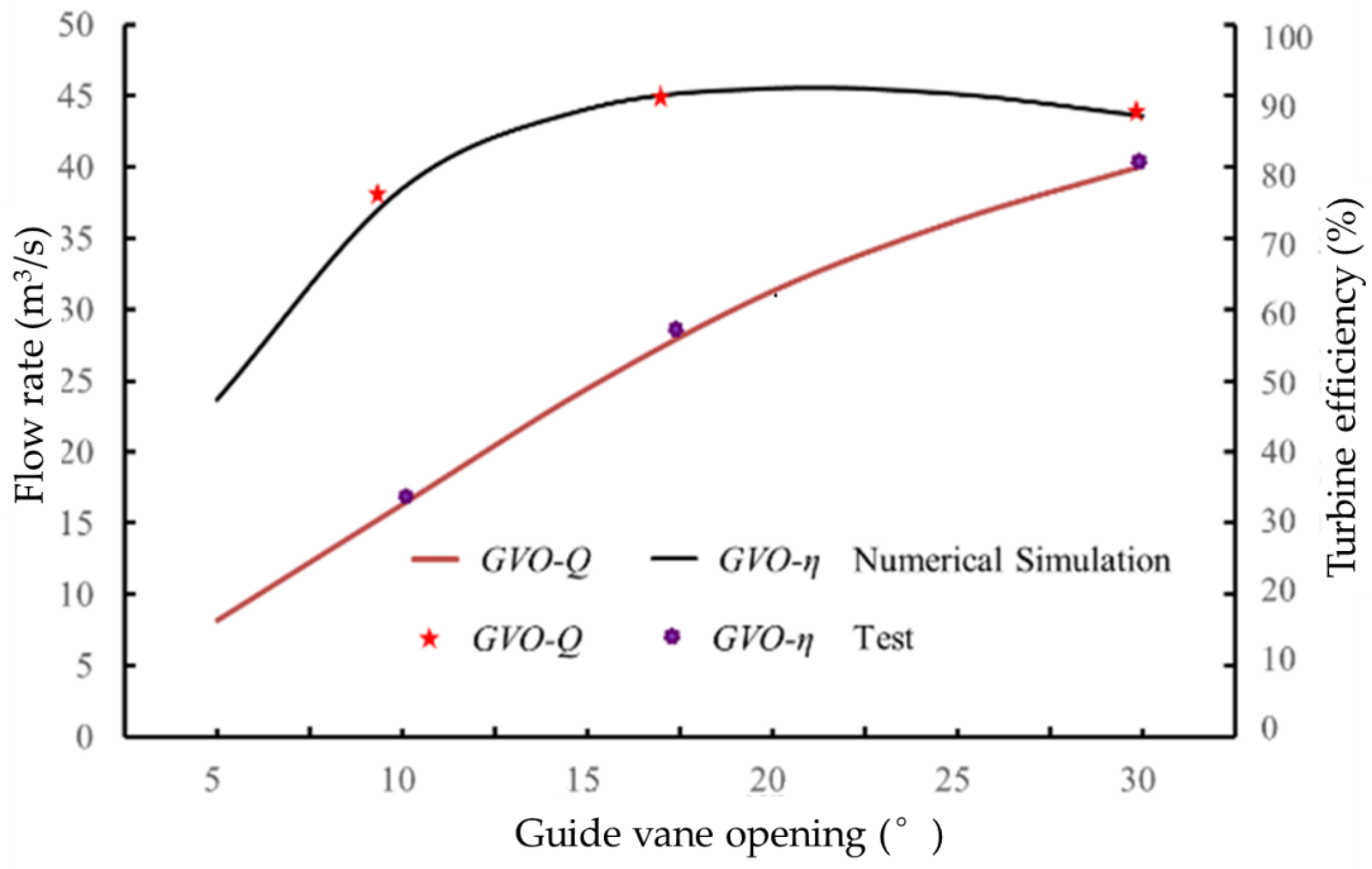
3.1. Reliability Verification of Calculation Model

Erosion in the turbine is the damage caused by wear for a long time. Numerical simulation wear prediction is an ideal method in which there are some basic assumptions, therefore there are inevitable errors between the prediction results and the actual erosion results on site. On the whole, the clearance wear is consistent with the wear characteristics of water turbine on the project site (see Figure 4), and external characteristics of hydraulic turbine obtained by simulation is consistent with that of unit operation on site (see Figure 5). The calculation results of external characteristics and wear show that the numerical simulation method is reliable.

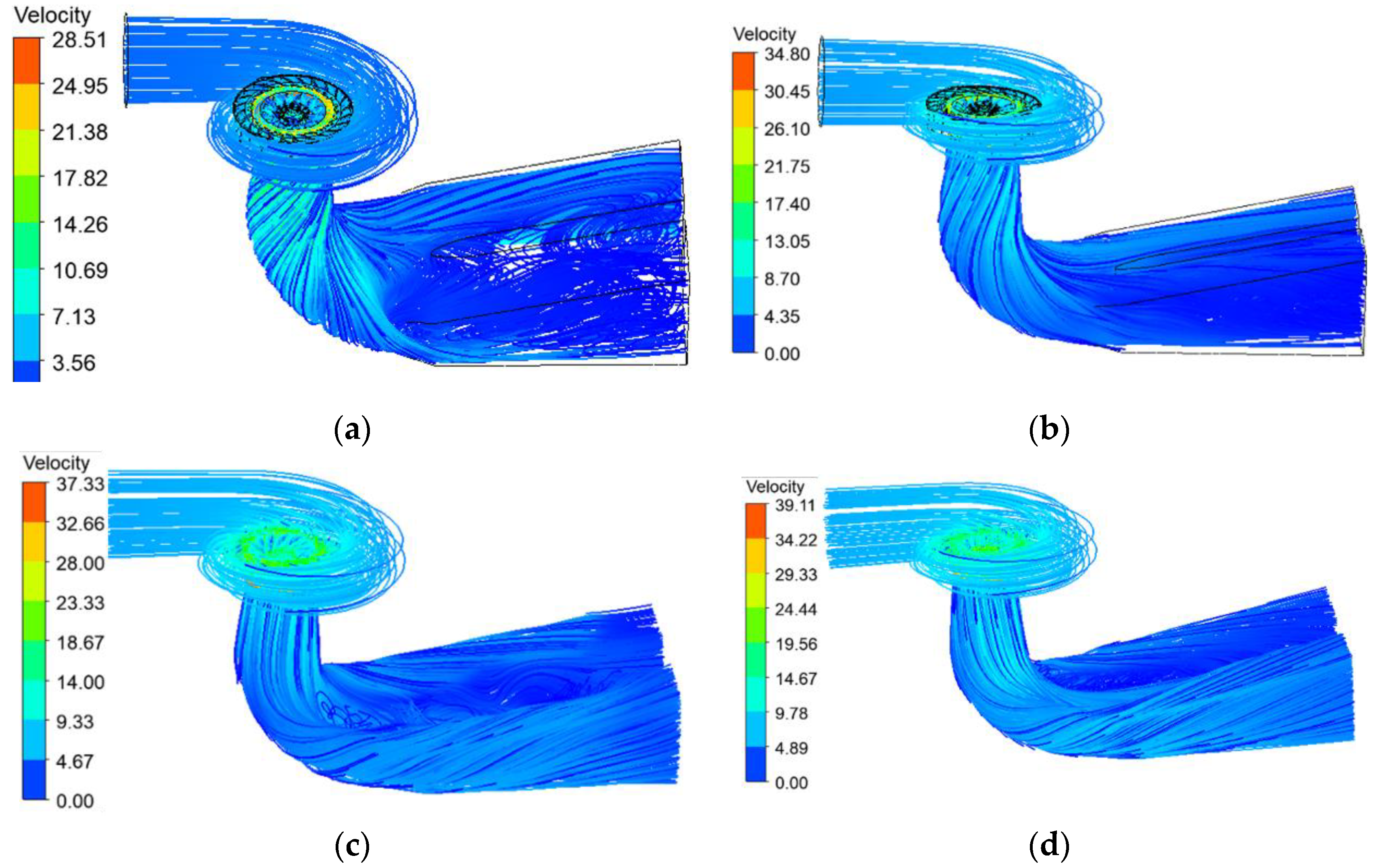
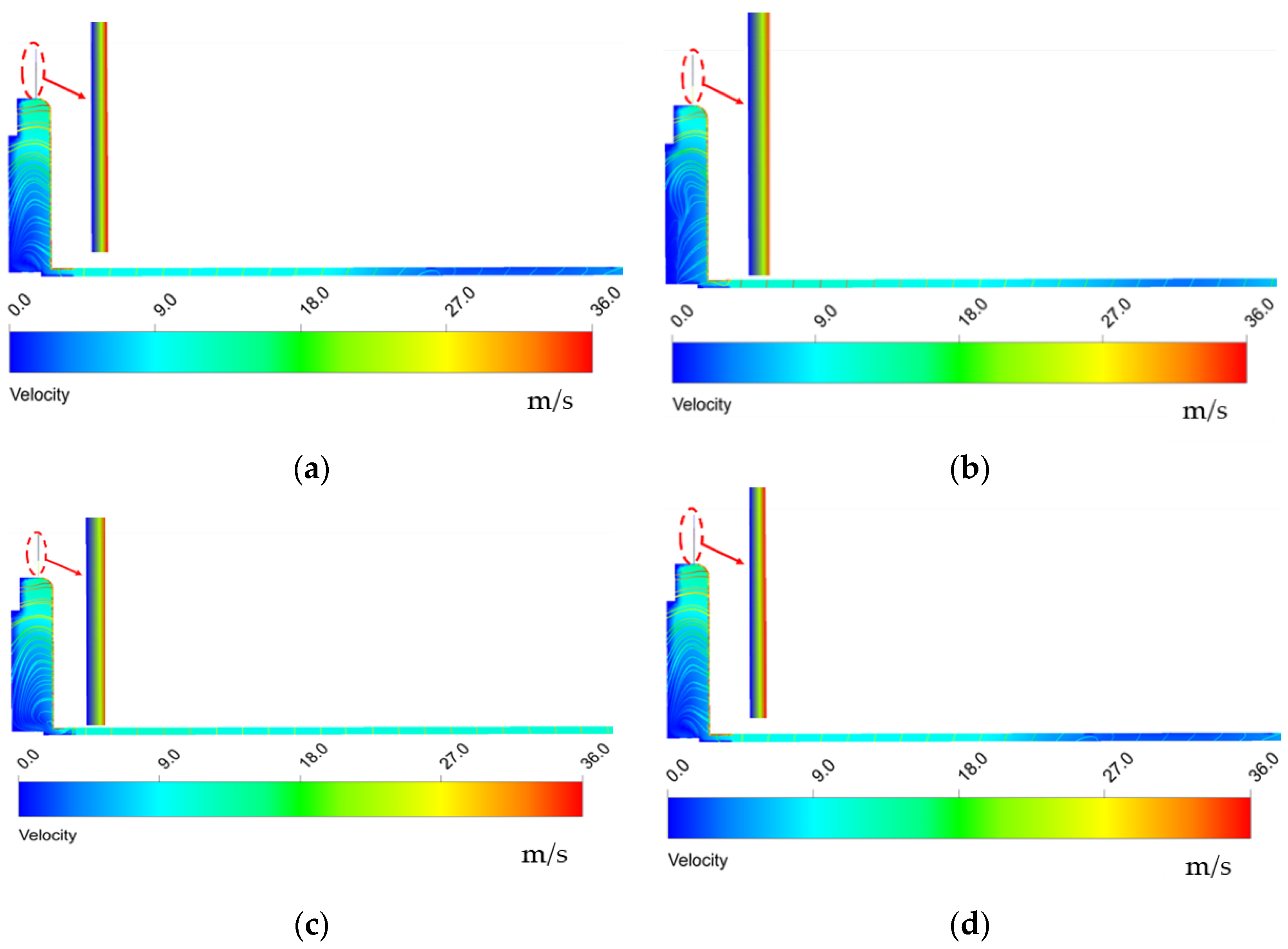
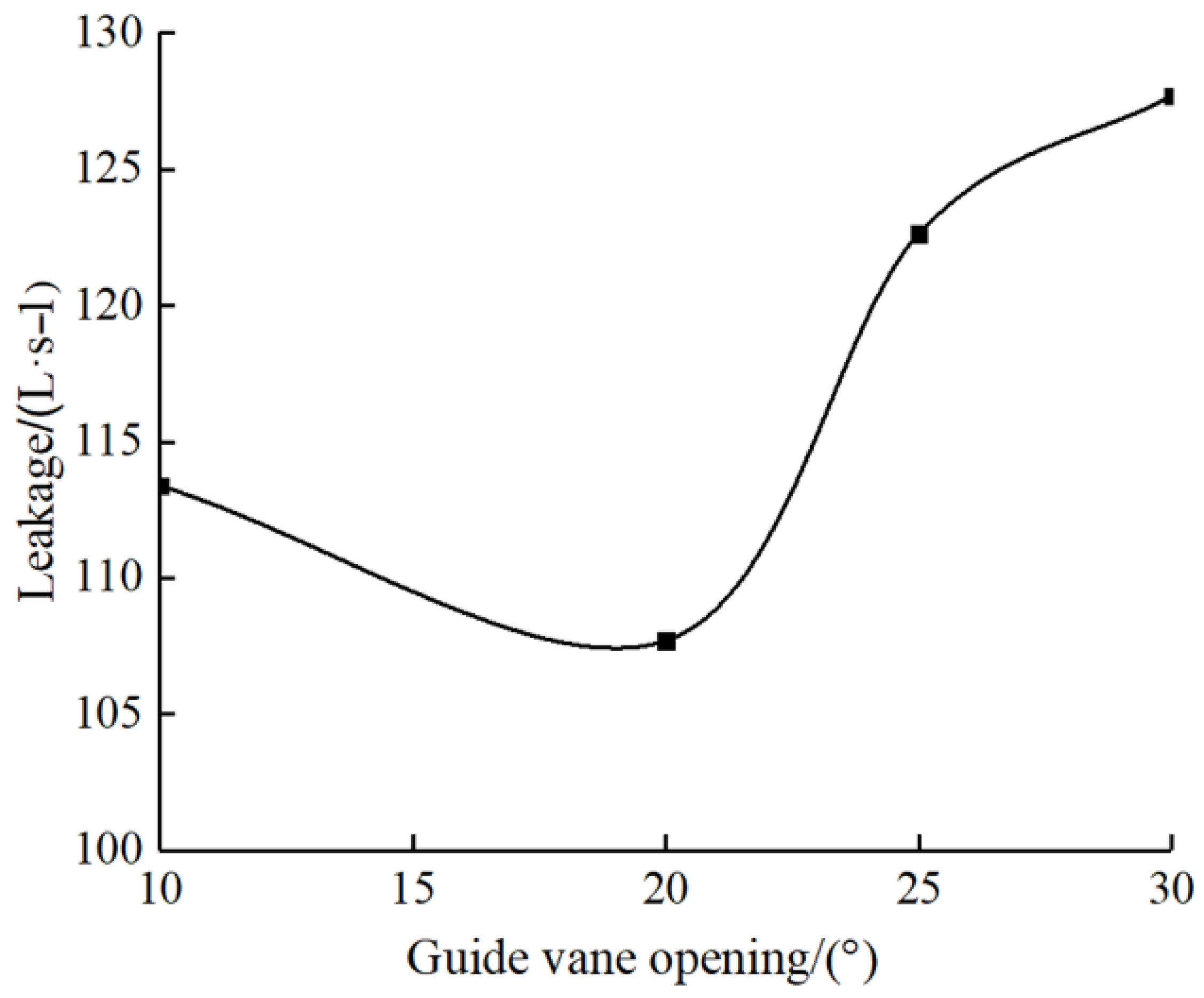
3.2. Flow Analysis under Different Guide Vane Opening

Figure 6 is a three-dimensional flow pattern in the flow channel of the turbine unit with different guide vane openings. The maximum flow velocity in the flow channel under different opening degrees of 10°, 20°, 25°, and 30° is 28.5 m/s, 34.8 m/s, 37.3 m/s, and 39.1 m/s, respectively, which indicates that the larger the opening of the guide vane, the greater the flow velocity in the unit. When the guide vane opening is 20° and 25°, the overall flow in the flow channel of the unit is most smooth, which indicates that the flow is most stable under the optimal working condition. When the guide vane opening is 30°, there is large-scale turbulence in the draft tube, and the unstable flow in the draft tube will spread upstream, affecting the flow pattern in the runner and the guide vane.
Further analyze the flow pattern evolution law under different guide vane openings and select the velocity vector on the longitudinal section passing through the center of the unit for analysis. Figure 7 shows the velocity distribution of the longitudinal section in the channel under different guide vane openings. In the guide vane and runner part, there are great differences under different opening degrees. The center of the elbow tube section at 10° is free of flow, which is due to the existence of the draft tube vortex in the draft tube when the opening is small, which makes the draft tube free of flow. At 25°, the flow pattern at the elbow in the draft tube has been greatly improved, and there is no tail water vortex, which further verifies the flow stability in the unit under this working condition. The flow patterns at different positions in the axial direction of the 30° guide vane runner is very different. This further verifies that the unsteady flow in the draft tube will propagate to the unit and change the flow structure in the unit.

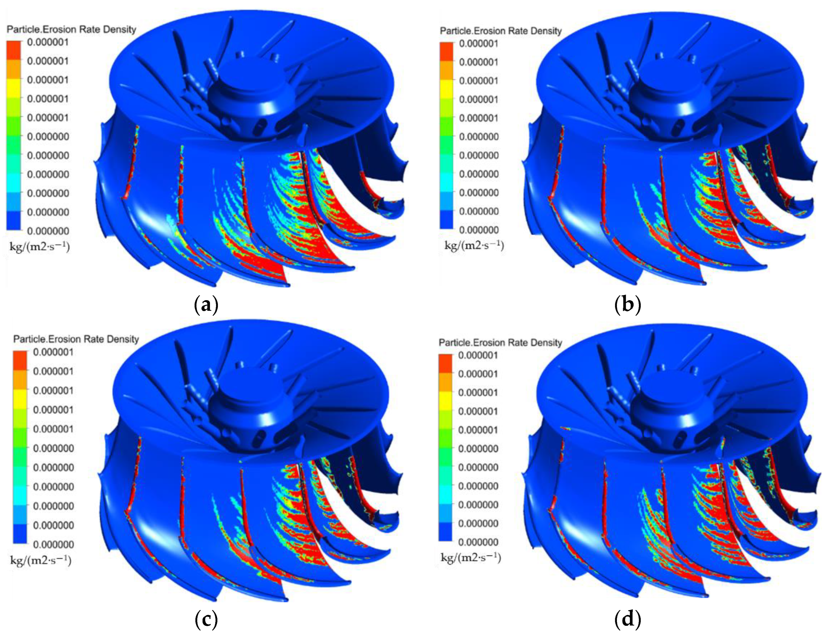
3.3. Analysis of Runner Wear under Different Guide Vane Opening

The runner is the core component of the hydraulic turbine. The wear on the runner blades under different guide vane openings is analyzed. Figure 8 shows the runner wear distribution under different guide vane openings. The wear position in the runner is mainly concentrated on the blade inlet head and the blade outlet working surface. In wear tribology, the wear is divided into impact wear and friction wear. The impact wear is point-like, and the friction wear is strip-like. The wear patterns at different positions show that the blade head is impact wear, the blade outlet surface is mainly friction wear, and the friction wear occurs on the blade surface along the movement trajectory of particles. On the whole, with the increase of the guide vane opening, the wear of the runner blade heads increases, while the friction and wear on the outlet side of the blade surface decreases with the increase of the guide vane opening.

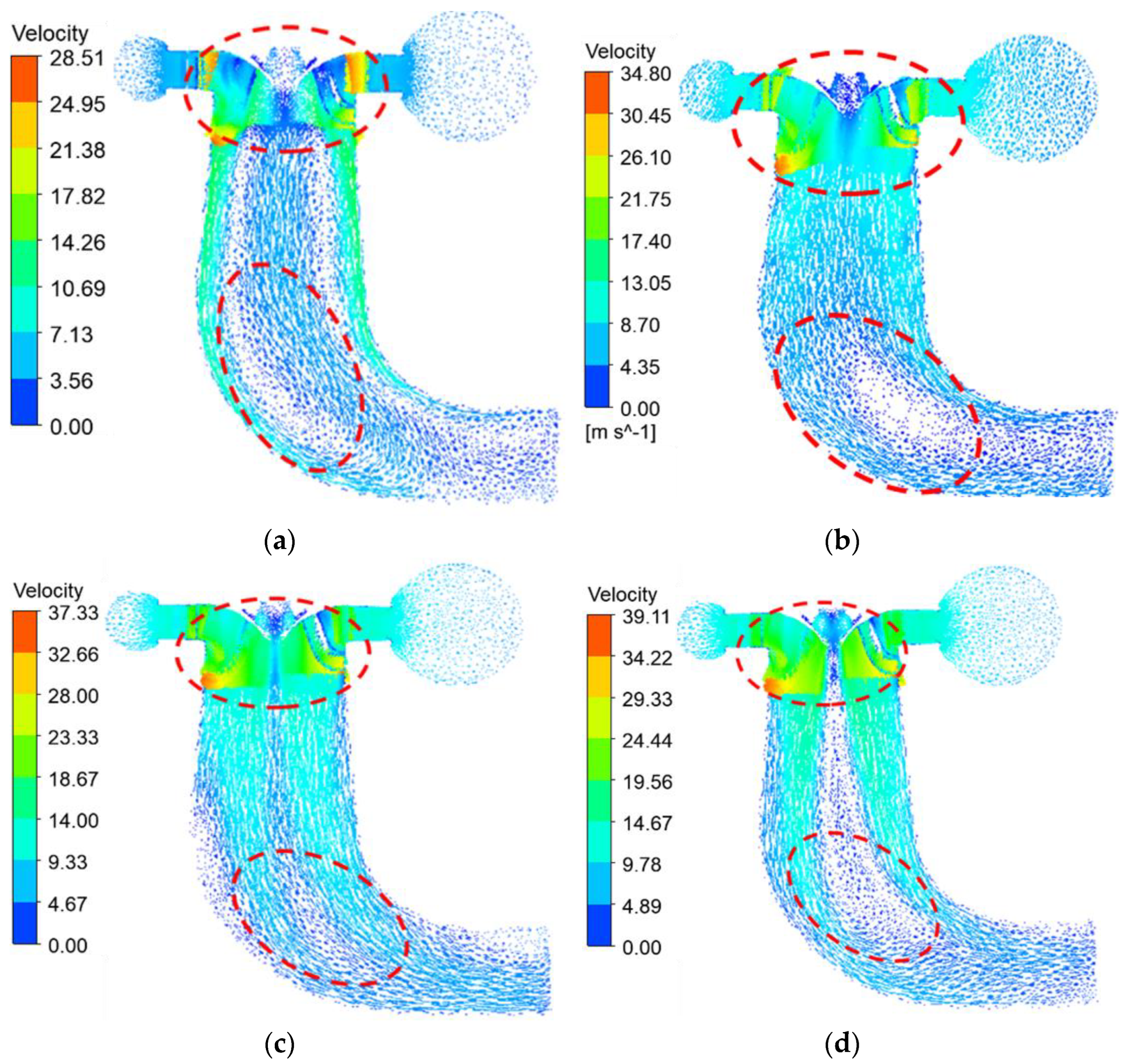
3.4. Particle Flow in the Lower Annulus under Different Guide Vane Opening

Further analyze the particle movement characteristics in the band cavity and visualize the particle movement in the axial direction and the circumferential direction in the band cavity. Figure 9 shows the particle movement trajectory in the band under different guide vane openings, and Figure 10 shows the particle movement trajectory and velocity distribution in the band under different guide vane openings. The leakage amount in the band clearance under different guide vane openings is counted, as shown in Figure 11. Under the rotation of the runner, the sediment particles in the annular cavity rotate around the center of the runner in the lower annular cavity with the water flow, and constantly generate friction and collision with the lower annular wall. The upper part of the band cavity is a high-speed area, and the particle velocity in the lower part of the band is small, which indicates that the upper part of the band is more vulnerable to sediment abrasion. There are differences in the motion trajectories of particles in the band cavity under different guide vane opening. When the guide vane opening is 10° and 20°, the particles in the bottom of the band cavity have unstable motion in the circumferential direction. When the guide vane opening is 25° and 30°, the particles in the band cavity tend to move stably in the circumferential direction, as shown in Figure 9. When the guide vane opening is 10° in the axial direction of the band cavity, the flow state is most smooth. When the guide vane opening is 30°, there is vortex backflow in the axial direction of the band cavity. The existence of backflow hinders the longitudinal flow of water in the band cavity. The band wall surface of the upper clearance of the band is a high-speed area, as shown in Figure 10. The movement law of particles in the band cavity under different opening degrees indicates that the smaller the guide vane opening is, the easier the leakage of the band cavity is, and the larger the guide vane opening is, the smaller the leakage of the band cavity is. The unsteady flow in the band disturbs the motion trajectory of particles changes the impact angle of particles and affects the wear in the band.

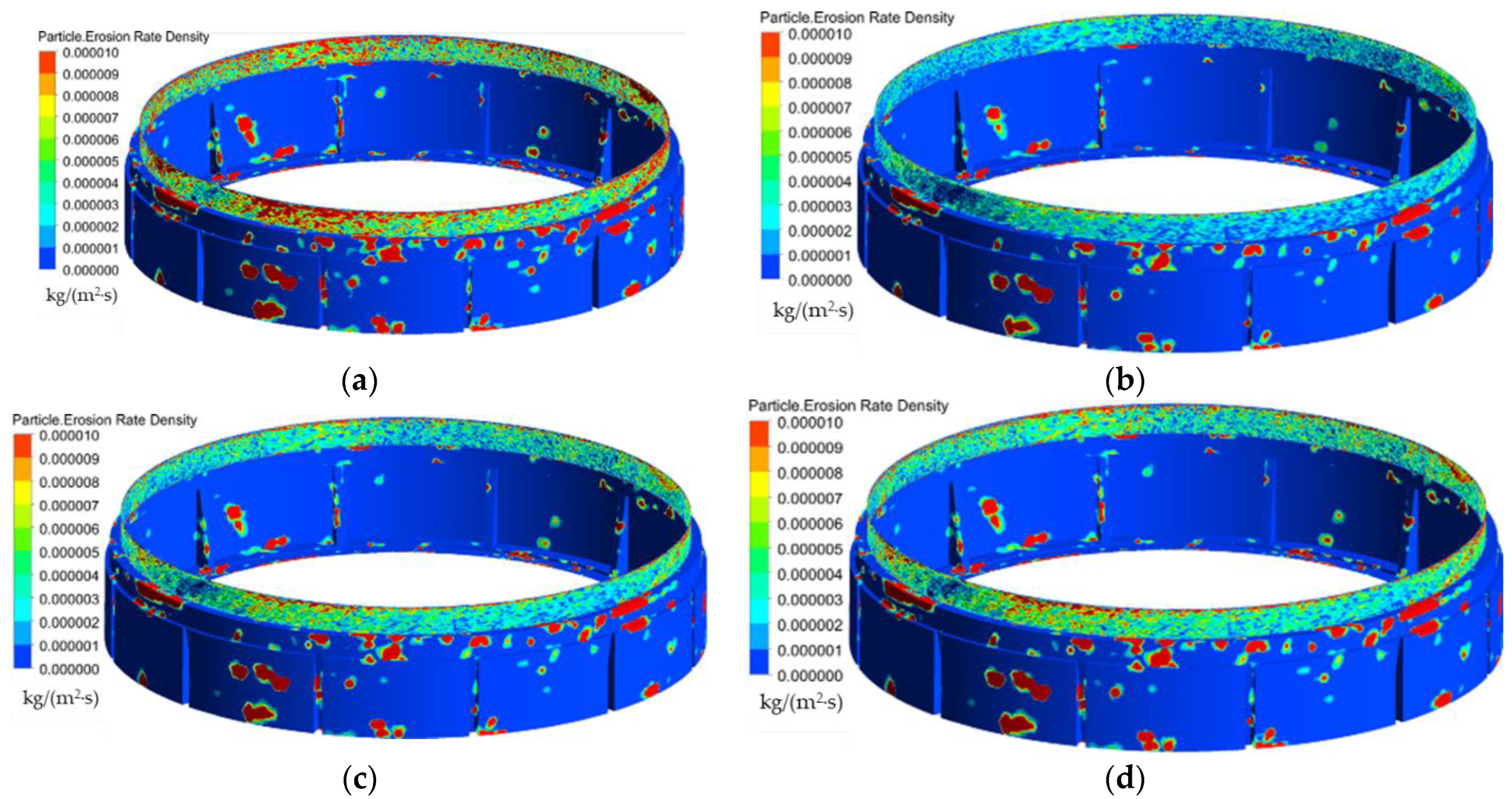
3.5. Erosion in the Band Clearance

After fully understanding the movement law of particles in the band cavity, the wear of the inner wall of the band cavity is visually analyzed. Figure 12 shows the wear rate distribution in the band cavity under different guide vane openings. The wear position in the band is mainly concentrated at the clearance position. The wear degree in the band clearance is obviously more serious than that in other positions. There are also different degrees of wear in the non-clearance position of the band cavity, which indicates that the clearance wear will cause serious damage to the safe operation of the unit and increase the leakage amount of the clearance. When the guide vane opening is 10°, the wear at different positions of the band is the most serious, especially the clearance wear. The wear in the clearance will decrease when the guide vane opening is increased. The change law of wear in the band clearance under different openings is consistent with the change law of clearance leakage and speed in the clearance.

4. Conclusions

1. In this paper, the Lagrangian particle tracking model is used to simulate and predict the sediment laden flow of the unit under different guide vane openings, and the particle movement law and the clearance wear of the band under different guide vane openings are analyzed. The predicted results are consistent with the field wear characteristics.
2. The influence of guide vane opening on particle movement in non-clearance main flow channel and clearance flow channel was investigated. The flow pattern in the guide vane and runner varies greatly under different opening degrees. The larger the opening of the guide vane, the larger the flow velocity in the main channel and the more stable the flow. Under the rotation of the runner, the sediment particles in the annular cavity rotate around the center of the runner in the lower annular cavity with the water flow and constantly generate friction and collision with the lower annular wall. The smaller the guide vane opening is, the easier the leakage of the band clearance is. The larger the guide vane opening is, the smaller the leakage of the band clearance is. The unsteady flow in the band disturbs the motion trajectory of particles changes the impact angle of particles and affects the wear in the band.
3. The blade head is subject to impact wear, and the blade outlet surface is mainly subject to friction wear, and friction wear occurs on the blade surface along the movement trajectory of particles. On the whole, with the increase of the guide vane opening, the wear of the runner blade heads increases, while the friction and wear on the outlet side of the blade surface decreases with the increase of the guide vane opening. When the guide vane opening is 10°, the wear at different positions of the band is the most serious, especially the clearance wear. The wear in the clearance will decrease when the guide vane opening is increased. The change law of wear in the band clearance under different opening is consistent with the change law of clearance leakage and speed in the clearance.

Author Contributions

Data curation, X.S.; software, validation, X.Z.; formal analysis, investigation, H.S.; resources, J.D.; writing—original draft preparation, X.S.; writing—review and editing, Z.W. All authors have read and agreed to the published version of the manuscript.

Funding

This work was supported by Project of research on sediment abrasion mechanism of turbine and research and development of anti-abrasion runner in Tagak Hydropower Station (XHTS-A-WZ-2022-005). National Natural Science Foundation of China (51876099).

Institutional Review Board Statement

Not applicable.

Informed Consent Statement

Not applicable.

Data Availability Statement

Not applicable.

Conflicts of Interest

The authors declare no conflict of interest.

References

  1. Ansari, B.; Aligholami, M.; Khosroshahi, A.R. An experimental and numerical investigation into using hydropower plant on oil transmission lines. Energy Sci. Eng. 2022. [Google Scholar] [CrossRef]
  2. Takaffoli, M.; Papini, M. Numerical simulation of solid particle impacts on Al6061-T6 part I: Three-dimensional representation of angular particles. Wear 2012, 292, 100–110. [Google Scholar] [CrossRef]
  3. Song, X.; Liu, C. Zhengwei Wang. Prediction on the pressure pulsation induced by the free surface vortex based on experimental investigation and Biot-Saval Law. Ocean Eng. 2022, 250, 110934. [Google Scholar] [CrossRef]
  4. Song, X.; Luo, Y.; Wang, Z. Numerical prediction of the influence of free surface vortex air-entrainment on pump unit performance. Ocean Eng. 2022, 256. [Google Scholar] [CrossRef]
  5. Cheng, X.; Dong, F.; Yang, C. The influence of particle diameter on friction loss intensity and collision wear loss intensity along blades of centrifugal pump. J. Lanzhou Univ. Technol. 2015, 41, 44. [Google Scholar]
  6. Song, X.; Liu, C. Experimental investigation of floor-attached vortex effects on the pressure pulsation at the bottom of the axial flow pump sump. Renew. Energy 2019, 145, 2327–2336. [Google Scholar] [CrossRef]
  7. Matsumura, T.; Shirakashi, T.; Usui, E. Identification of Wear Characteristics in Tool Wear Model of Cutting Process. Int. J. Mater. Form. 2008, 1, 555–558. [Google Scholar] [CrossRef]
  8. Koirala, R.; Thapa, B.; Neopane, H.P.; Zhu, B. A review on flow and sediment erosion in guide vanes of Francis turbines. Renew. Sustain. Energy Rev. 2017, 75, 1054–1065. [Google Scholar] [CrossRef]
  9. Qian, Z.; Gao, Y.; Zhang, K.; Huai, W.; Wu, Y. Influence of dynamic seals on silt abrasion of the impeller ring in a centrifugal pump. Proc. Inst. Mech. Eng. Part A J. Power Energy 2013, 227, 557–566. [Google Scholar] [CrossRef]
  10. Zhang, Y.; Qian, Z.; Ji, B.; Wu, Y. A review of microscopic interactions between cavitation bubbles and particles in silt-laden flow. Renew. Sustain. Energy Rev. 2016, 56, 303–318. [Google Scholar] [CrossRef]
  11. Smirnov, P.E. Sensitization of the SST turbulence model to rotation and curvature by applying the Spalart–Shur correction term. J. Turbomach. 2009, 131, 1407–1419. [Google Scholar] [CrossRef]
  12. Guo, B.; Xiao, Y.; Rai, A.K.; Zhang, J.; Liang, Q. Sediment-laden flow and erosion modeling in a Pelton turbine injector. Renew. Energy 2020, 162, 30–42. [Google Scholar] [CrossRef]
  13. Menter, F.R. Two-equation eddy-viscosity turbulence models for engineering applications. AIAA J. 1994, 32, 1598–1605. [Google Scholar] [CrossRef]
  14. Xianbei, H.; Qiang, G.; Baoyun, Q. Prediction of Air-Entrained Vortex in Pump Sump: Influence of Turbulence Models and In-terface-Tracking Methods. J. Hydraul. Eng. 2020, 146, 04020010. [Google Scholar]
  15. Celik, I.B.; Ghia, U.; Roache, P.J. Procedure for estimation and reporting of uncertainty due to discretization in CFD applications. J. Fluids Eng. 2008, 130, 078001-1–078001-4. [Google Scholar]
  16. Zeise, B.; Liebich, R.; Prölß, M. Simulation of fretting wear evolution for fatigue endurance limit estimation of assemblies. Wear 2014, 316, 49–57. [Google Scholar] [CrossRef]
  17. Shrestha, U.; Chen, Z.; Park, S.H.; Choi, Y.D. Numerical studies on sediment erosion due to sediment characteristics in Francis hydro turbine. IOP Conf. Ser. Earth Environ. Sci. 2019, 240, 042001. [Google Scholar] [CrossRef]
  18. Shen, Z.; Chu, W.; Li, X.; Dong, W. Sediment erosion in the impeller of a double-suction centrifugal pump—A case study of the Jingtai Yellow River Irrigation Project, China. Wear 2019, 422–423, 269–279. [Google Scholar] [CrossRef]
  19. Gautam, S.; Neopane, H.P.; Thapa, B.S.; Chitrakar, S.; Zhu, B. Numerical Investigation of the Effects of Leakage Flow From Guide Vanes of Francis Turbines using Alternative Clearance Gap Method. J. Appl. Fluid Mech. 2020, 13, 1407–1419. [Google Scholar]
  20. Xijie, S.; Chao, L. Experiment study of the floor-attached vortices in pump sump using V3V. Renew. Energy 2021, 164, 752–766. [Google Scholar] [CrossRef]
  21. Fan, M.; Yanjun, L.; Ji, P. Energy Characteristics of Full Tubular Pump Device with Different Backflow Clearances Based on Entropy Production. Appl. Sci. 2021, 11, 3376. [Google Scholar]
  22. Karakas, E.S.; Watanabe, H.; Aureli, M.; Evrensel, C.A. Cavitation Performance of Constant and Variable Pitch Helical Inducers for Centrifugal Pumps: Effect of Inducer Tip Clearance. J. Fluids Eng. 2020, 142, 1–19. [Google Scholar] [CrossRef]
  23. Daqiq Shirazi, M.; Torabi, R.; Riasi, A. The effect of wear ring clearance on flow field in the impeller sidewall gap and efficiency of a low specific speed centrifugal pump. Proc. Inst. Mech. Eng. Part C (J. Mech. Eng. Sci.) 2018, 232, 3062–3073. [Google Scholar] [CrossRef]
  24. Takaffoli, M.; Papini, M. Numerical simulation of solid particle impacts on Al6061-T6 Part II: Materials removal mechanisms for impact of multiple angular particles. Wear 2012, 296, 648–655. [Google Scholar] [CrossRef]
  25. Zhu, Y.; Lu, J.; Liao, H.; Wang, J.; Fan, B.; Yao, S. Research on cohesive sediment erosion by flow: An overview. Sci. China Technol. Sci. 2008, 51, 2001–2012. [Google Scholar] [CrossRef]
Figure 1. Model of numerical simulation.
Jmse 10 01396 g001
Figure 2. Clearance grids.
Jmse 10 01396 g002
Figure 3. Efficiency of turbine with different grid numbers.
Jmse 10 01396 g003
Figure 4. Erosion at the inlet of the stay guide vane. (a) CFD result; (b) Wear physical picture.
Jmse 10 01396 g004
Figure 5. Reliability verification of external characteristics of hydraulic turbine.
Jmse 10 01396 g005
Figure 6. Overall flow pattern in the channel under different guide vane opening. (a) 10°, (b) 20°, (c) 25°, (d) 30°.
Jmse 10 01396 g006
Figure 7. Overall flow velocity distribution in the channel under different guide vane opening. (a) 10°, (b) 20°, (c) 25°, (d) 30°.
Jmse 10 01396 g007
Figure 8. Runner wear under different guide vane opening. (a) 10°, (b) 20°, (c) 25°, (d) 30°.
Jmse 10 01396 g008
Figure 9. Particle trajectory in the band under different guide vane opening. (a) 10°, (b) 20°, (c) 25°, (d) 30°.
Jmse 10 01396 g009
Figure 10. Particle trajectory and velocity distribution in the vertical section of the band under different guide vane opening. (a) 10°, (b) 20°, (c) 25°, (d) 30°.
Jmse 10 01396 g010
Figure 11. Leakage in band clearance under different guide vane opening.
Jmse 10 01396 g011
Figure 12. Erosion distribution of band under different guide vane opening. (a) 10°, (b) 20°, (c) 25°, (d) 30°.
Jmse 10 01396 g012
Publisher’s Note: MDPI stays neutral with regard to jurisdictional claims in published maps and institutional affiliations.

