1. Introduction
Harmonics are sinusoidal voltages or currents of frequencies that are integer multiples of the frequency at which the supply system is designed to operate. Current harmonics are more crucial than voltage harmonics because in most situations, the voltage harmonics only occur when there are current harmonics inside the power system. Current harmonics may result from nonlinear load operations produced by power electronic devices and applications which are injected into the supply network through a point of common coupling (PCC). Specifically, in smart grid systems, these problems may arise with involvement of multiple energy sources and systems which include photovoltaic (PV) grid connected systems [
1,
2,
3,
4,
5,
6]. Among the effects of current harmonics are capacitor blowing, equipment overheating, motor vibration and excessive neutral currents [
7,
8]. To compensate current harmonics, a powerful tool is the active power filter (APF), which is better as compared to a passive filter, since it can mitigate multiple harmonics instantaneously. Furthermore, for current harmonics mitigation or compensation, shunt active power filters (SAPF) or transformer-less APF topology is widely used [
9,
10,
11]. However, besides SAPF, there are other topologies to compensate current harmonics, and among them are the third harmonics injection and the loss-free complex impedance (LFCI) [
12,
13]. The third harmonic injection uses almost same topology (full bridge inverter) as SAPF to generate injection current for current harmonics mitigation. As this approach only focuses compensation of the third harmonic order only, SAPF is definitely preferable to compensate all order of harmonics order up to the 25th. In addition, the third harmonics injection also does not cover power factor correction which causes the source current to not be in phase with the source voltage [
12]. For the LFCI, its function is almost same as SAPF, where it can mitigate current harmonics and correct power factorss. It mitigates current harmonics directly at the load side by controlling the switching signal of the rectifier, and also by emulating a certain degree of input capacitance without any physical capacitance [
13]. Differently, SAPF mitigates current harmonics by indirectly extracting harmonics and injecting back the current to the grid for mitigation purpose. As a result, LFCI is more complicated as compared to SAPF as it has to emulate the capacitance in order to mitigate current harmonics [
13].
Integrating PV with SAPF is among the best options as this type of energy is among the most popular renewable energy sources since it is clean, inexhaustible, and free to harvest [
14]. In future perspective, the prices of PV panels are getting lower by about 4%–12% each year [
15]. In addition, the PV panels mostly have quite long lifetimes of about 25 years [
16,
17]. Even though the existing PV modules in the market have low efficiency (15%), with the huge development of the latest PV cell technology and in addition to the use of nanotechnology, their efficiencies can be improved by up to 40% [
18,
19]. Meanwhile, normal SAPF extracts source current from the grid to charge the dc link capacitor. Considering the high electricity tariffs now and in the future [
20], the charging process of the dc link capacitor will lead to incremental cost and strong dependency on the grid power. By having additional PV sources integrated with SAPF, this will reduce the usage of electricity from the source grid. Subsequently, integration of PV to SAPF is worthwhile due to the reduction of PV prices, long lifetime, improved efficiency and lowered usage of electricity. For functionality of PV with SAPF, the injection current consists of not just reactive current but also active current. Normal SAPF mitigates current harmonics by injecting the reactive current, but when it is operated with PV, it does not just mitigate current harmonics but also reduces source current simultaneously. With active and reactive injections to the source grid, the power quality of the grid can be improved with low total harmonic distortion (THD) values [
21]. Besides reducing the source current, by integrating PVs with SAPF, the active current is also supplied to the load sides which simultaneously reduces the burden of the source current to satisfy the load demand [
22]. The normal SAPF based on voltage source inverter needs to absorb active power to charge the dc link capacitor, but with integration of PV to SAPF, the PV source does not just producing active current to the grid but also helping to maintain the dc link capacitor by giving additional charging current [
23].
In addition, the wide and easy installation of PV modules on the roof tops of building and also at minimal space locations provide flexibility and opportunity to connect them with any type of power electronic converter [
24]. Installation of SAPF to be close to the PV source seems to be possible too, which provides strong motivation for integrating both of them. Basically, the higher the irradiance, the higher the power of the PV, which leads to lower power consumption from the grid to supply the load, or specifically can be in related to the reduction of source current. However, change of irradiance and subsequently inappropriate injection of current from SAPF may degrade the performance of the overall system.
The role of the harmonics extraction algorithm is important in order to ensure an appropriate injection current from SAPF. Through better injection, the SAPF should be able to compensate harmonics optimally [
25,
26]. Numerous methods have been used to extract harmonics in past research works, which include d-q axis with Fourier (DQF) [
27,
28,
29], instantaneous reactive power theory (p−q) theory [
30], adaptive filters [
31], wavelet [
32], synchronous reference frame (SRF) [
33], synchronous detection [
34], artificial neural network (ANN) [
35], and many more. ANN is the latest trend because of its capability to perform fast, accurately and stably. Specifically, for SAPF, ANN will accurately estimate or extract time-varying fundamental components, both the magnitude and the phase angle, to mitigate harmonic components [
36,
37].
There are numerous ANN architectures for harmonics extraction such as adaptive linear neuron (ADALINE), Perceptron, Back propagation (BP), radial basis function (RBF), Hopfield, Hebbian, Competitive, and Grossberg [
38,
39]. Among them, ADALINE is preferable because of it only consists of one linear system and its simplicity to perform a good harmonics extraction. A number of works have been carried out using ADALINE for current harmonics extraction. One of them is a single linear neuron model method, which is called as Widrow-Hoff (W-H) ADALINE Neural Network. However, the disadvantage of W-H ADALINE is it must learn multiple harmonic components which had an effect on the learning time of the algorithm itself [
39,
40]. Improvements have been carried out to improve the algorithm by focusing directly on extraction of the fundamental component with a suitable learning rate in updating the algorithm, which is called modified Widrow-Hoff (W-H) ADALINE [
35,
39,
41].
Further improvements have to be made because the existing improvemente are still considered as having needless features which do not represent the basic requirements for extracting current harmonics in power systems. With these needless features, some drawbacks affect performance of the Modified W-H ADALINE such as the large size average error and slow learning rate due to the cosine component and weight factor that may affect its time response, and as a result, delay in compensation [
42]. As PV is known to be dynamically affected by changes of irradiance, the harmonics extraction algorithm plays crucial function to maintain proper and fast response injection current with additional PV current to mitigate the current harmonics existing in the power system.
This paper first presents integration of PV to SAPF with significant investigation on generation of active PV currents. Second, a new simplified and improved ADALINE neural network for harmonics extraction is proposed, which is later called the fundamental active current (FAC) ADALINE algorithm. In the proposed algorithm, three major improvements have been made to the learning updating technique, sine and cosine vector, and sum of elements. Evaluation of the proposed algorithm under significant effect of PV sources will be carried out to confirm its effective operation in SAPF. Reduction of THD, response time, and source power from grid should be verified. Further explanation on the proposed SAPF with active PV current, new proposed current harmonics extraction algorithm, simulation and experimental results, and conclusions are presented
Section 2,
Section 3,
Section 4,
Section 5 and
Section 6, respectively.
2. Integration of Photovoltaic with Shunt Active Power Filter
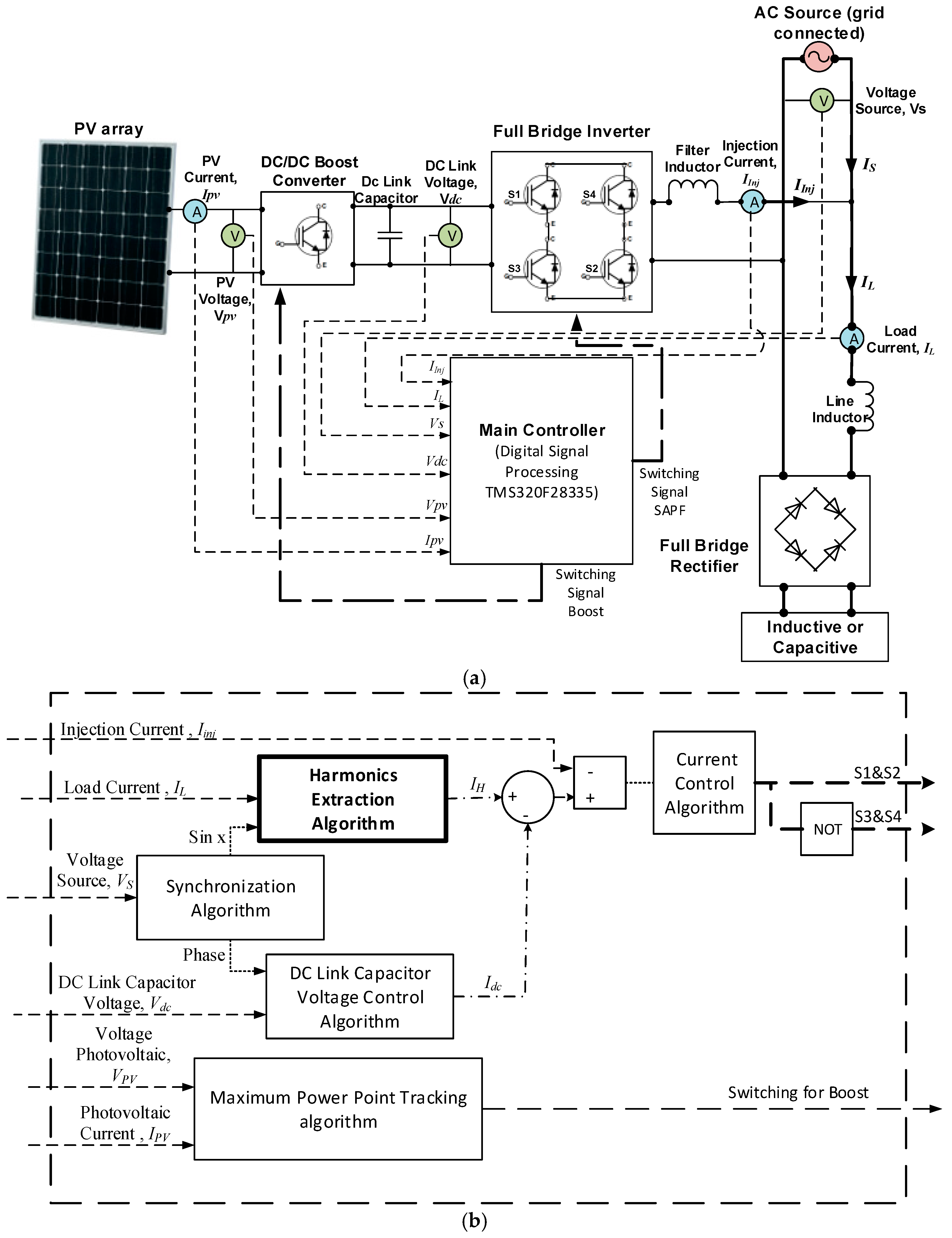
Figure 1 shows a block diagram of a SAPF connected with a PV array and the control strategies inside it. Without PV, nonlinear-load operation contains load current
IL, which comprises fundamental component
If and harmonic component
IH, both present within the grid source current
IS, polluting the power system. After the SAPF is connected, it generates an injection current
Iinj which then compensates the harmonic current produced by the load, as shown below:
The injection current
Iinj is generated from the inverter-based configuration of SAPF, or can be defined as
Iinv. If the inverter current
Iinv is equal to harmonic current
IH, then source current
IS will only comprise the fundamental component
If. Meanwhile, by arranging Equation (1) and using inverter current
Iinv, the load operates based on combination of source current
IS and inverter current
Iinv, as shown below:
However, by connecting PV, as shown in
Figure 1a, the PV current
IPV is injected together with inverter current
Iinv, or:
Considering with the same amount of current needed by the load before and after connecting the PV, the source current
IS should be reduced with significant effect from the PV current
IPV. Therefore, the injection current
Iinv at PCC now is combination of inverter current
Iinv and PV current
IPV, or:
The role of the injection current is crucial as it will determine performance of the SAPF with the combination of PV sources. Fast and accurate injection current will lead to better operation of the SAPF. The PV current to be added to the system is totally dependent on the irradiance of the Sun. High irradiance will give a high PV current which leads to low current usage taken from the grid system. According to Equation (4), the inverter current Iinv is controlled by the combination of the harmonics extraction algorithm and dc link capacitor voltage control, and meanwhile, the PV current is controlled by the maximum power point tracking (MPPT) algorithm.
The size of the PV array is fully dependent on the configuration of the SAPF and power rating of the source grid. By connecting PV, the SAPF may operate with a full bridge inverter to be directly connected to PVs, which is called as single-stage configuration, or with addition of a dc/dc converter, which is called two-stage configuration [
21,
22,
23]. The advantage of the single-stage configuration is lower power losses; however, it needs a higher number of PV modules in order to supply enough voltage to the dc link capacitor, which may make the overall system become bigger. Meanwhile, by having a two-stage configuration, although it may have losses, a lesser number of PV modules is required, which directly reduces the cost. In addition, there is the flexibility of controlling the PV voltage for a dc link capacitor. Thus, this work uses a two-stage configuration, as shown in
Figure 1. In terms of power rating, the SAPF with PV works well as long as the maximum power of the PV array is not above the rating of the source power. Higher maximum power of the PV array over the source power will result in inaccurate current injection for the purpose of harmonics mitigation. The proposed PV module used is a monocrystalline silicon type with the characteristics listed in
Table 1.
The PV modules connected in an array are connected to boost the dc/dc converter used to step up the PV voltage and is the medium where the maximum power point tracking (MPPT) algorithm works. The main function of the MPPT algorithm is to track and maintain the maximum power point of the PV array according to the irradiance. The boost dc/dc converter is connected to a full bridge inverter through a dc link capacitor. In the integration of PV and SAPF, the main part is the controller which covers all the control strategies, including MPPT algorithm, harmonics extraction algorithm, dc link capacitor voltage control algorithm, synchronization algorithm, and current control algorithm. As shown in
Figure 1b, the highlighted algorithm is the harmonics extraction algorithm. For the MPPT algorithm, a so-called adaptive perturb and observe (P&O)-fuzzy algorithm is used due to its better performance of tracking the maximum power point under dynamic operations [
43]. To control the dc link capacitor voltage, self-charging with step size error cancellation is used [
44]. As current control algorithm, a linear current control algorithm which consists of a proportional-integral (PI) technique for steady state error control, with pulse width modulation (PWM) for producing switching signals for power switching devices, is chosen because its simplicity and easy implementation [
36,
41,
45]. The value for proportional gain (
kp) is 200 and the integral gain (
ki) is 37. A synchronizer based on the ANN method, or called as unified ADALINEs-based fundamental voltage extraction algorithm, is used to produce a reference sinusoidal signal [
46]. The source of harmonics is from a rectifier-based circuit with nonlinear loads, connected to the grid, which produces current harmonics in electrical power systems [
47,
48,
49,
50,
51,
52].
3. Fundamental Active Current ADALINE Algorithm
As explained earlier, the proposed harmonics algorithm is based on significant improvements to the Modified Widrow-Hoff (W-H) ADALINE, as successfully implemented in [
35,
36,
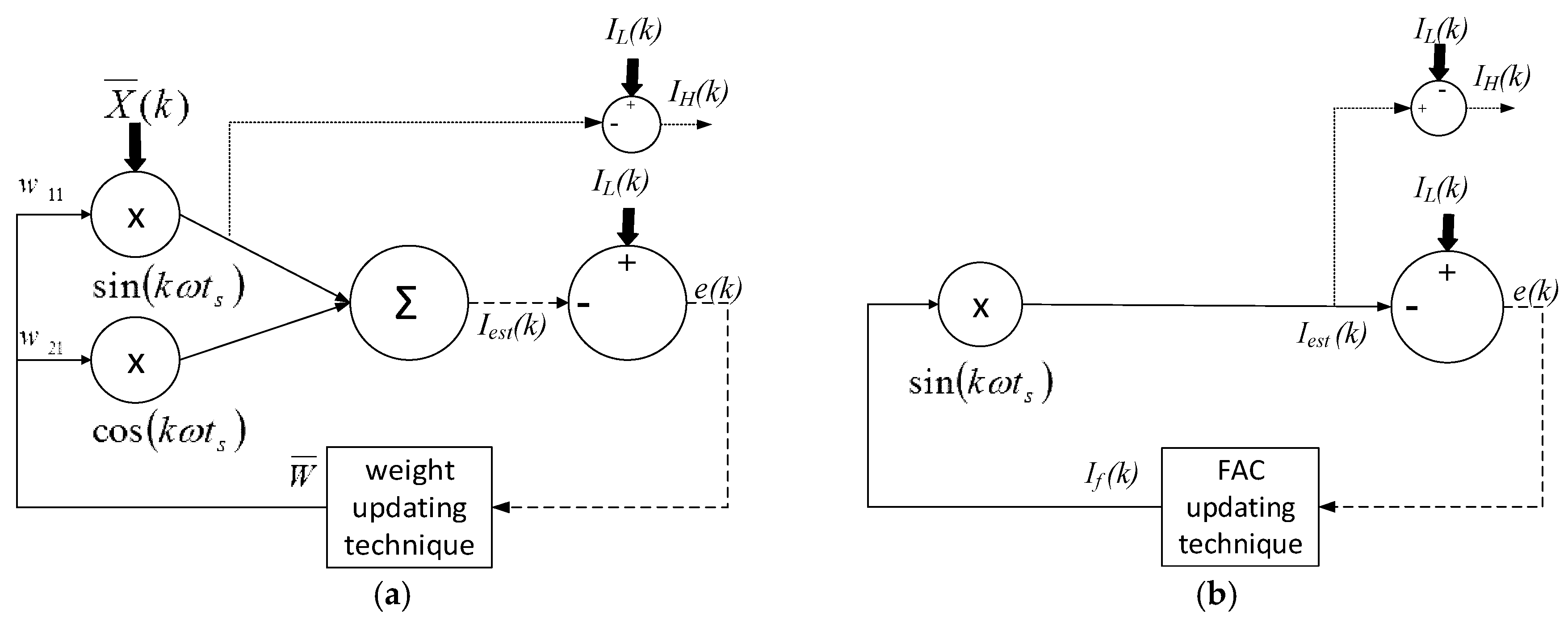
41]. As to ensure clear understanding, some significant parts of the Modified W-H ADALINE are explained first. The Modified W-H ADALINE uses the first order of harmonic component as shown in
Figure 2a. It needs only to update the two weights of the fundamental component, making it independent of the number of harmonic orders. This improvement is based on the mathematical relationship of the elements being orthogonal to each other. This modification leads to enhanced iteration speed which resulting in faster estimation. However, updating only the two weights results in a large average square error e, and thus learning rate α must be added as in Equation (5) [
35]. Average square error
e(k) is the difference between the actual measured signal
IL(k) and the estimated signal
Iest(k):
where:
is the weight factor;
is the fundamental sin and cosine;
is the average square error;
α is the learning rate.
A suitable learning rate is important as it will help the algorithm optimally produce an accurate distorted current fundamental [
35]. Good compromise between accuracy and speed should be considered in order to have the optimum value, as too low a value may result in slow performance, but too high a value may result in the algorithm failing to achieve high accuracy. Meanwhile, in practical approach, the fundamental sin and cosine can be formed based on the referenced sinusoidal signal produced by the synchronizer, as introduced earlier. The harmonic current
IH(k) can be produced from load current deduction (from load current’s fundamental sine part) as in Equation (6) [
35]:
As mentioned, although the Modified W-H ADALINE algorithm is capable of mitigating harmonics with THD to be below than 5%, but it still has some drawbacks that may affect the performance of the harmonics extraction, especially the time response to extract all the harmonics. Inside its algorithm, there are still needless features which do not represent the basic requirement of extracting current harmonics. Thus, the proposed algorithm simplifies and improves it. The three improvements are the cosine component is removed and only the sine component exists in periodic signal, the sum of elements is removed to minimize and control the large average square error
e, and proper representation of the learning updating technique from weight updating technique to FAC updating technique. All the improvements are shown in
Figure 2b. The first feature is removal of the cosine component in the periodic signal. In symmetrical theory, an odd function is inversely symmetrical about the
y-axis, which means only the sine component exists in the odd function of periodic signals. Since the cosine component is removed, automatically the second improvement can be made where the sum of elements is removed which reduces the large average square error
e. The last improvement is by representing the learning factor in the learning updating technique as in Equation (7):
The learning factor by using weight
W in Equation (6) does not give a clear representation for functionality of SAPF. The weight learning factor can be represented as the peak value of active fundamental current before it is multiplied by the sine component. To make it simpler and understandable, the real learning factor is directly renamed as FAC
If. This new renamed parameter will provide a better idea by directly giving information of required value for generating injection current. The FAC updating technique is shown in
Figure 2. The new equation of harmonic current is:
4. Simulation Results
A SAPF with PV array was developed and simulated using the MATLAB/Simulink simulation software.
Table 2 lists each component used for the proposed SAPF. The detailed calculations for determining the values of the dc link capacitor, dc/dc boost inductor and filtering inductor was based on [
53,
54]. Specifically, for the dc link capacitor, a bigger value is needed for minimizing the ripple voltage [
52,
55]. Two types of nonlinear loads were developed by using a diode H-bridge rectifier with 470 µF capacitor and 50 Ω resistor (capacitive load) connected in parallel as the first one, and meanwhile a 160 mH inductor and 15 Ω resistor (inductive load) connected in series for the second one. Duty cycle for dc/dc boost converter was set to 0.28. A dynamic operation test was done to evaluate the performance of both harmonics extraction algorithms. Dynamic operations are referred to the off-on operation between PV and SAPF, and change of irradiances for the PV source. For the first dynamic operation, the irradiance during off state was set to 0 W/m
2, and during on state was set to 600 W/m
2. Meanwhile, for the second dynamic operation, the change of irradiances is between low (200 W/m
2) to high (1000 W/m
2) irradiance. The sampling time for this simulation was set to 6.67 µs with sampling frequency of 150 kHz. The switching frequency for the switching signal of the power switching devices was set to 25 kHz. Meanwhile, the learning rate for both harmonics extraction algorithms was set to 0.001, as the setting approach has clearly been discussed in [
32,
50].
The FAC ADALINE algorithm was evaluated and compared with the Modified W-H ADALINE, as the existing algorithm [
35].
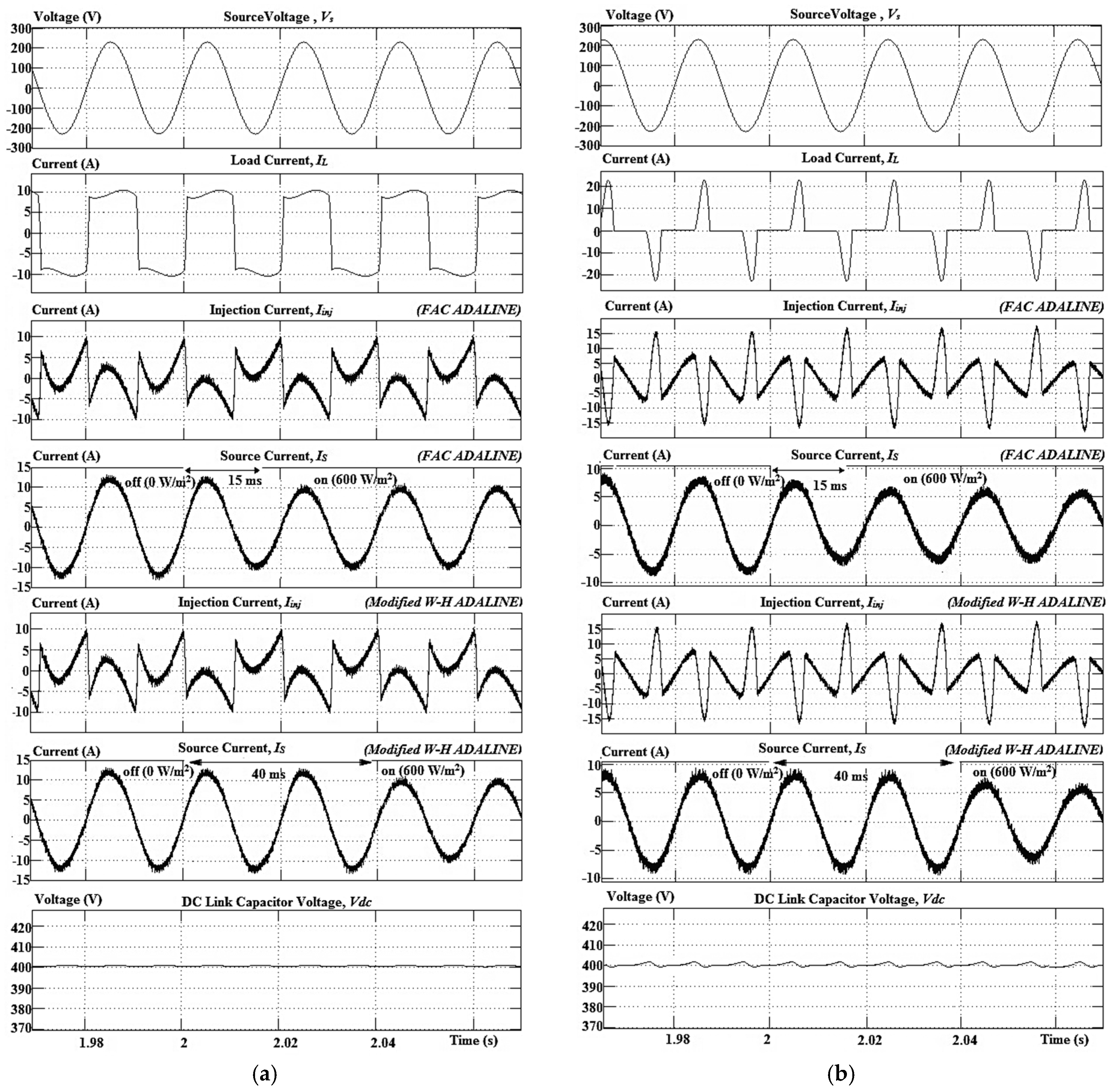
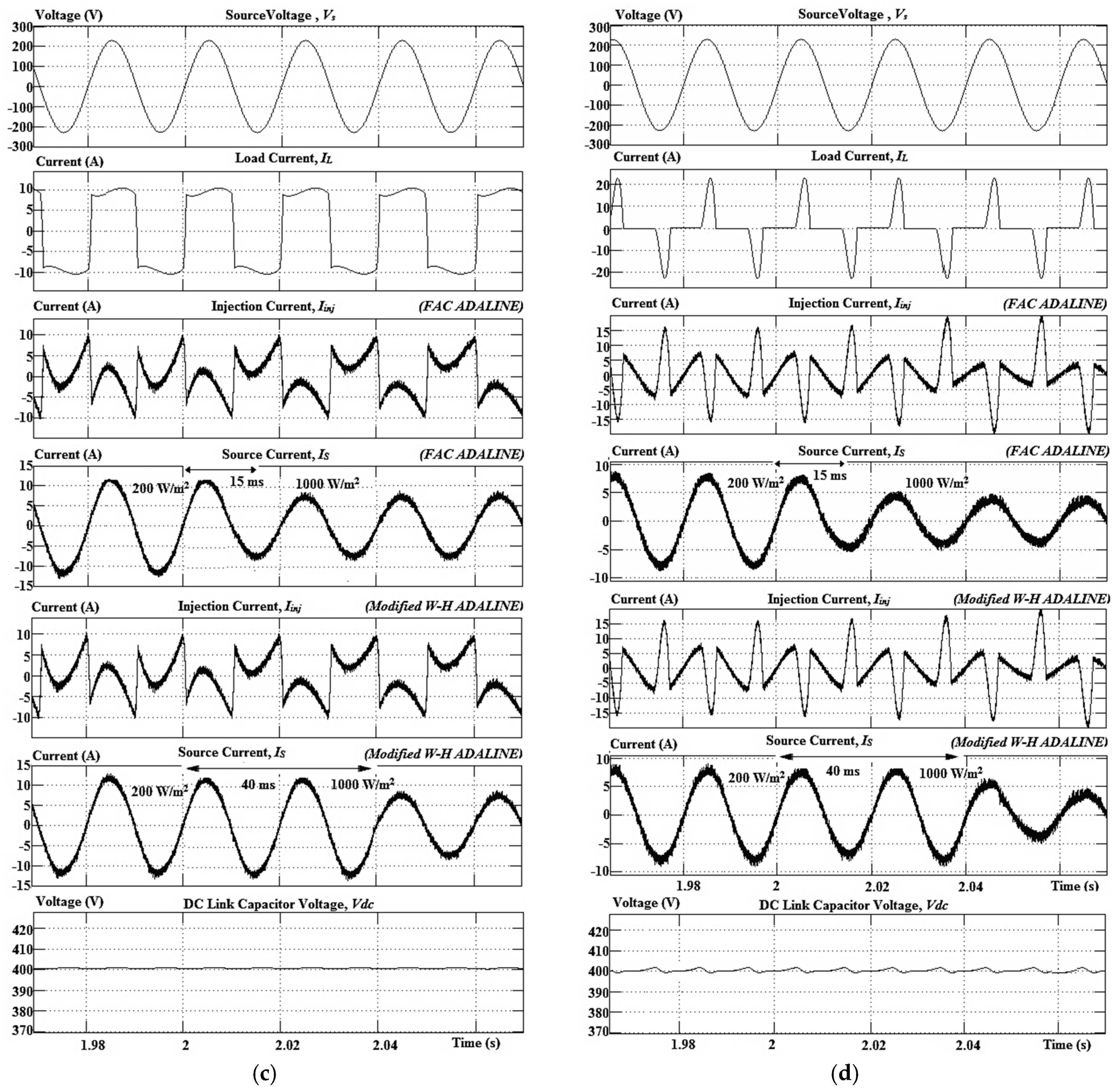
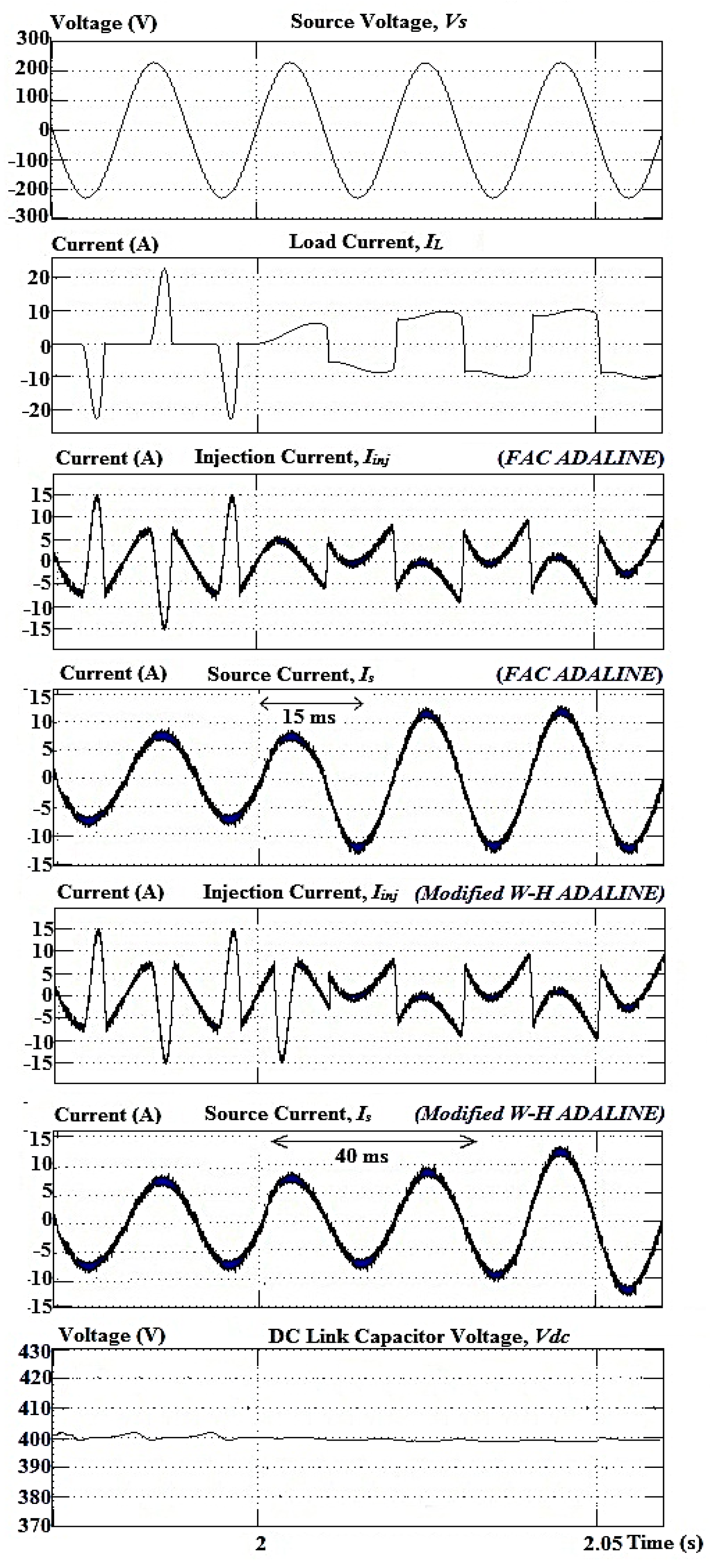
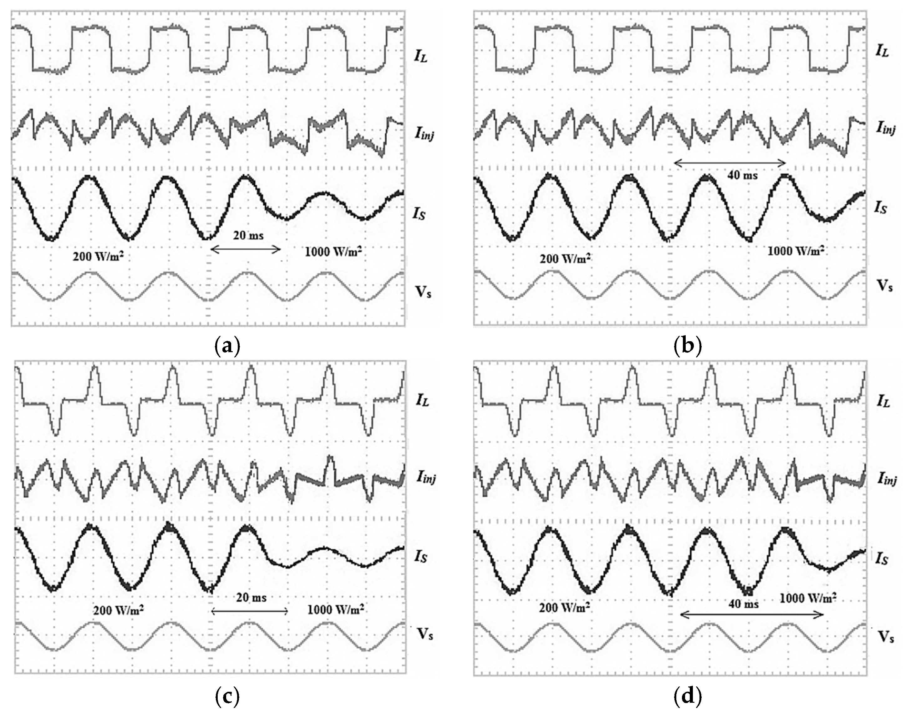
Figure 3 shows the results obtained for off-on operation and change of irradiances using capacitive and inductive loads. Meanwhile,
Figure 4 shows the results obtained for change between nonlinear loads.
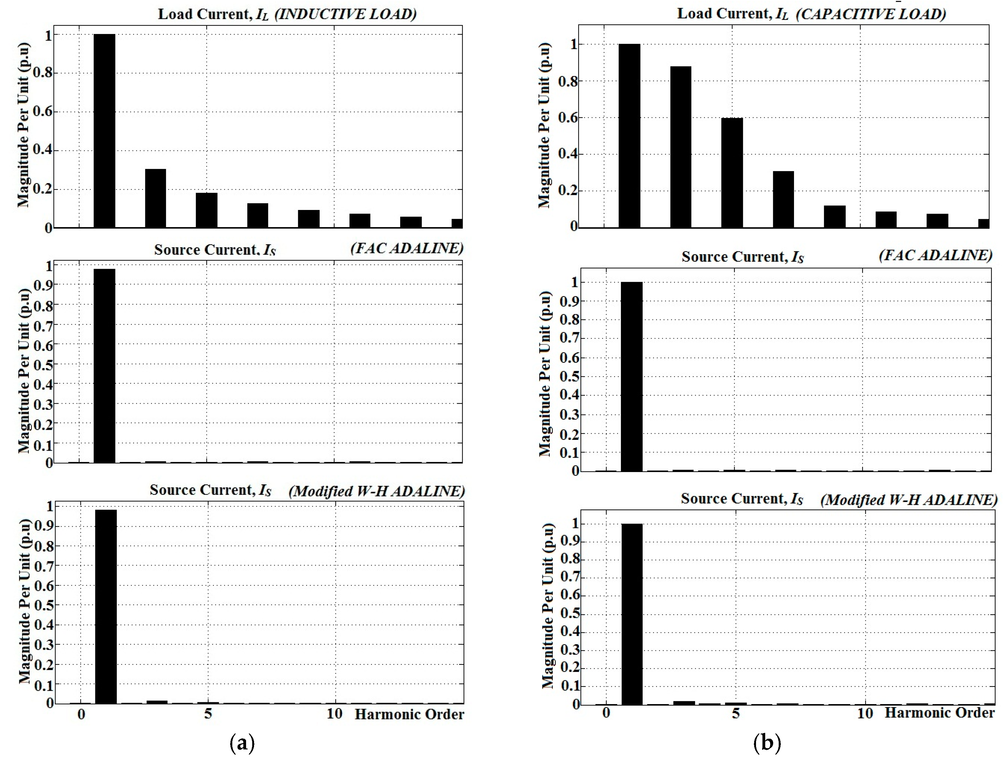
Figure 5 shows harmonics spectrum of the nonlinear loads’ currents and the source currents for operation of SAPF without PV. The nonlinear loads’ currents were recorded with THD in about 40.28% for inductive load, and meanwhile, for capacitive load, the THD is about 106.31%. Another additional analysis is power consumption required from the grid by considering integration of PV and SAPF. THD is also measured to evaluate significant effect due to injection of active PV current. By referring again to
Figure 3a,b, and
Figure 5 when the PV is in off condition (irradiance at 0 W/m
2), both algorithms show good source current waveforms with low THDs and very good elimination for all harmonic orders; yet, the proposed algorithm still gives the best results with better THD values, which are about 1.5% (inductive) and 2.29% (capacitive). Meanwhile, the existing algorithm gives about 2% (inductive) and 3.13% (capacitive). In addition, the source current is in phase with the source voltage.
When PV is connected to the SAPF, active current injection from the PV source will reduce the source current from the grid to supply and maintain the load current demand. This reduction will result in a small increase of the value of THD. With this condition, the harmonics extraction algorithms play a crucial role to maintain the THD value 5%. As shown in
Figure 3a,b too, when PV is in on condition (irradiance at 600 W/m
2), both algorithms have maintained the THD values within 5%, but the proposed algorithm gives the lower values for both nonlinear loads. The values are 1.8% (inductive) and 2.93% (capacitive), and meanwhile the existing algorithm gives about 2.3% (inductive) and 3.6% (capacitive). The same goes to the other two irradiances as shown in
Figure 3c,d, where at 200 W/m
2, the proposed algorithm produces better THD values, which are 1.57% (inductive) and 2.82% (capacitive), and meanwhile the existing algorithm gives about 2.14% (inductive) and 3.24% (capacitive).
At 1000 W/m
2, again, better THD values are obtained by the FAC ADALINE algorithm with 2.43% (inductive) and 3.24% (capacitive), and meanwhile the existing algorithm gives about 2.72% (inductive) and 3.86% (capacitive).
Table 3 provides detailed comparison of THD values between both algorithms with capacitive and inductive loads.
Besides supplying load, the power from grid used to supply and maintain the dc link capacitor voltage of SAPF is reduced and possibly eliminated, as already covered by the PV source. The additional PV source in the SAPF also provides an alternative energy source that reduces the burden of the source grid to provide power to the load. Operation of SAPF without PV normally absorbs active power (also known real power) from the source grid for maintaining the dc link capacitor voltage and at the same time produces reactive power as to be used for compensation. Interestingly a PV source, when integrated with SAPF, will only have an effect to reduce the absorbed active power, and the SAPF now can produce both active and reactive powers. To determine how much active power supplied from the grid is reduced due to function of PV, percentage of source power reduction
P% is proposed to be calculated as below:
where
PT is active power from the source grid when PV is in off condition (irradiance at 0 W/m
2) and
PS is active power from the source grid at certain irradiance. The
P% is also known as percentage of active power produced by SAPF. By referring again to
Figure 3, the actual active powers from the source grid when the PV is in off condition (irradiance at 0 W/m
2) are 2714 W by using inductive load and 1794 W by using capacitive load. The active powers absorbed by inductive and capacitive loads are 2300 W and 1520 W. Balanced active powers from the source grid are absorbed by SAPF. Meanwhile, reactive powers produced by the SAPF used for compensation are based on performances of the harmonics extraction algorithms.
By using the FAC ADALINE algorithm, the reactive powers produced for inductive and capacitive loads are 410 VAR and 270 VAR, respectively. Meanwhile, by using the Modified W-H ADALINE algorithm, the reactive powers produced are 403 VAR for inductive load and 264 VAR for capacitive load. The higher reactive powers produced by the proposed algorithm also show its better compensation performance. Furthermore, high performance of the harmonics extraction algorithm is needed in a SAPF with PV source, to have high reduction of the active power from the source grid. When the PV is in on condition at 600 W/m
2, the source powers greatly reduce by using the proposed algorithm, which are about 414 W (15%) for inductive load and 251 W (14%) for capacitive load, as compared to the existing Modified W-H algorithm with only 386 W (14.2%) for inductive load and 235 W (13.1%) for capacitive load. For irradiance at 200 W/m
2, as shown in
Figure 3c,d, the proposed algorithm reduces the source powers more, which are about 144 W (5.3%) for inductive load and 89 W (5%) for capacitive load, as compared to the existing Modified W-H algorithm with only about 124 W (4.6%) for inductive load and 72 W (4%) for capacitive load. The same goes for irradiance at 1000 W/m
2 where the proposed algorithm reduces the source powers higher, which are about 644W (23.7%) for inductive load and 403 W (22.5%) for capacitive load, as compared to the existing Modified W-H algorithm which only reduces about 614 W (22.6%) for inductive load and 382 W (21.3%) for capacitive load. The proposed algorithm basically extracts accurate current harmonics to produce accurate injection current. With high injection current accuracy, better and precise mitigation of harmonics can be achieved thus lowering use of the source current. Subsequently, reduction of the source power can clearly be seen as compared to the existing Modified W-H algorithm.
Table 4 and
Table 5 show details of the active powers including load power, source power and source power reduction by using both harmonics extraction algorithms for each nonlinear load.
Table 6 provides detailed comparison of percentages of source power reduction for both algorithms with capacitive and inductive loads. The results show that the FAC ADALINE algorithm has not only helped the SAPF to perform with lower THD values, but also to have high percentage of power reduction, as compared to the existing algorithm.
In term of response times under dynamic operations during off-on between PV and SAPF, and change of irradiances, the proposed algorithm shows better performance with only response time of 15 ms (capacitive and inductive). The existing Modified W-H algorithm however needs about 40 ms (capacitive and inductive), which is two cycles for 50 Hz system. Additional dynamic operation by changing the nonlinear loads was done, and as referred to
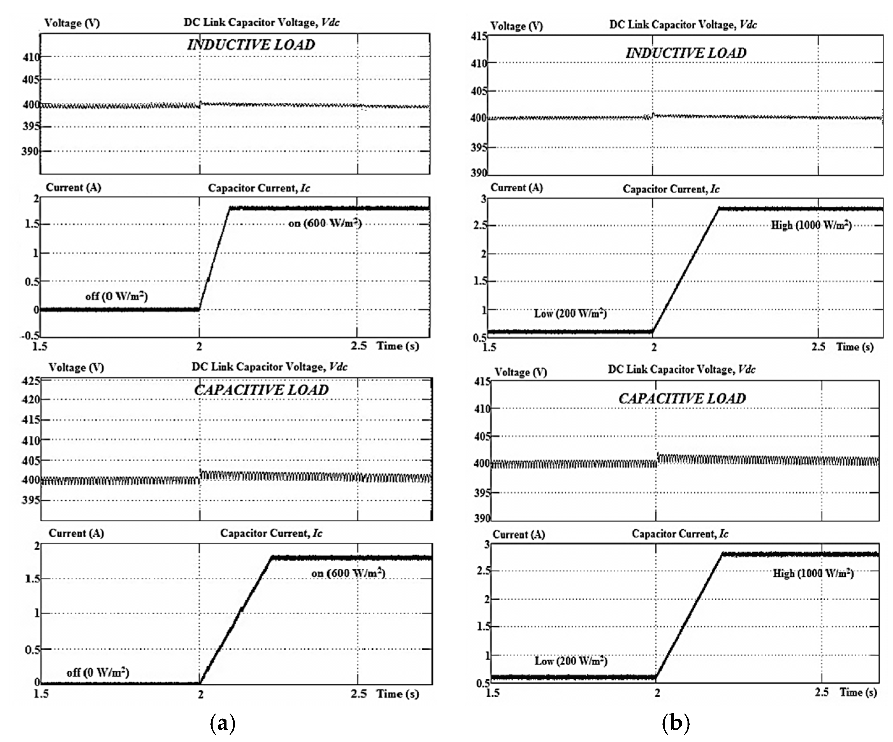
Figure 4, the proposed algorithm also produces response time of 15 ms as compared to the existing algorithm which only gives response time of 40 ms. Performance of dc link capacitor has been investigated too for off-on between PV and SAPF, and change of irradiances from low to high, as shown in
Figure 6.
There are negligible overshoots for the capacitor voltage and response time about 0.2–0.3 s, and for both harmonics extraction algorithms, no difference (or same condition) is observed since it is well controlled separately by the self-charging with the step size error cancellation algorithm. These negligible overshoots should ensure both harmonics extraction algorithms are not affected to perform their functions. With better THD values, high percentage of source power reduction and faster response time, the FAC ADALINE algorithm clearly improves performance of harmonics extraction which eventually provides a better SAPF system with integration of the PV source.
5. Experimental Results
A hardware prototype of the SAPF was developed to further test and verify the proposed algorithm. A PV simulator (62100H-600S, CHROMA, Taoyuan County, Taiwan) was used as PV source by implementing the characteristics of a NT-180U1 PV module (SHARP, Huntington Beach, CA, USA). This prototype used the same load configurations as in the simulation work with voltage source of 100 V
rms and dc link capacitor voltage of 200 V
dc. A TMS320F28335 digital signal processor (DSP, Texas Instruments, Dallas, TX, USA) was used to implement the harmonics extraction algorithms, together with MPPT, dc link capacitor voltage control, synchronization and current control algorithms. Like in the simulation, two dynamic operations were carried out, which are the off-on operation between PV and SAPF, and change of irradiances from low to high. When PV is in off condition, the irradiance is at 0 W/m
2, and when PV is in on condition, the irradiance is at 600 W/m
2. For the second dynamic operation, low irradiance is set at 200 W/m
2, and meanwhile, high irradiance is set at 1000 W/m
2.
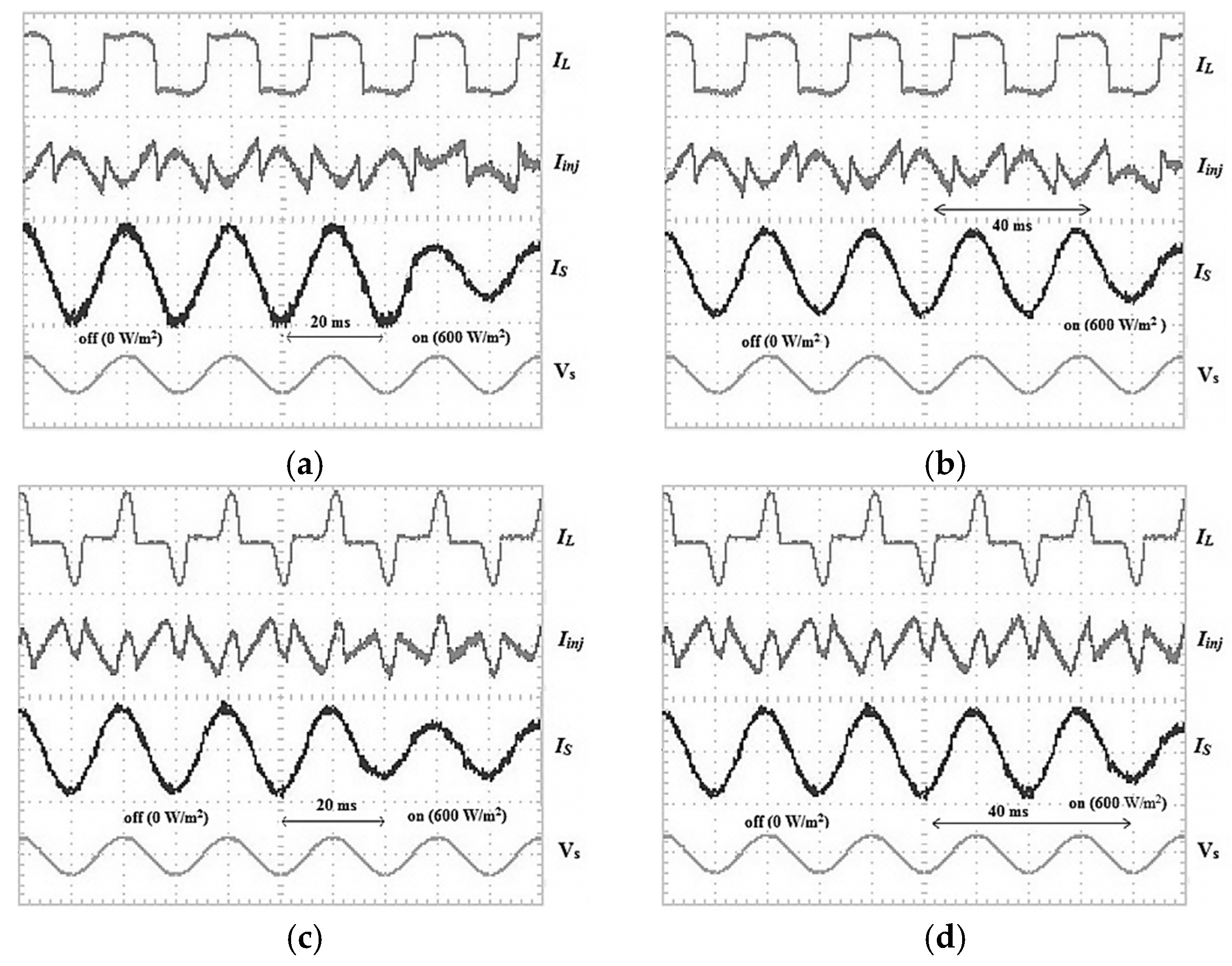
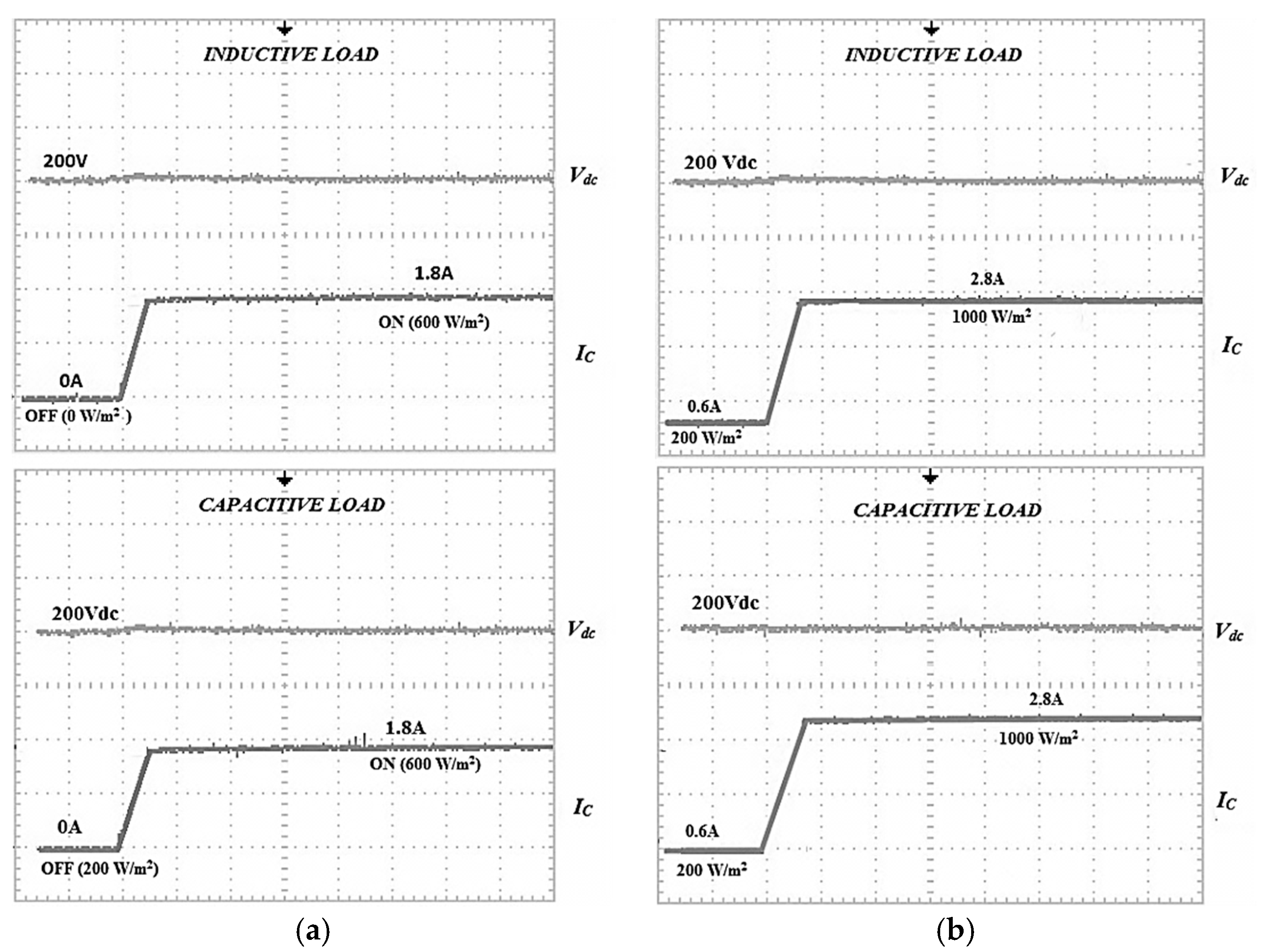
Figure 7 shows the results obtained for the first dynamic operation for each harmonics extraction algorithm with two nonlinear loads.
Figure 8 shows the second dynamic operation for each harmonics extraction algorithm with two nonlinear loads.
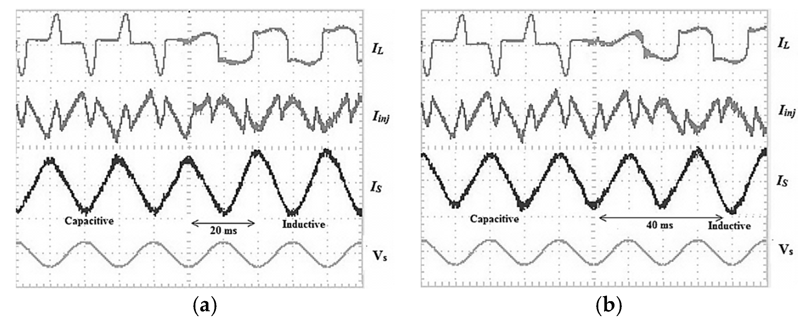
Figure 9 shows the additional dynamic operation involving change of nonlinear loads for each harmonics extraction algorithm.
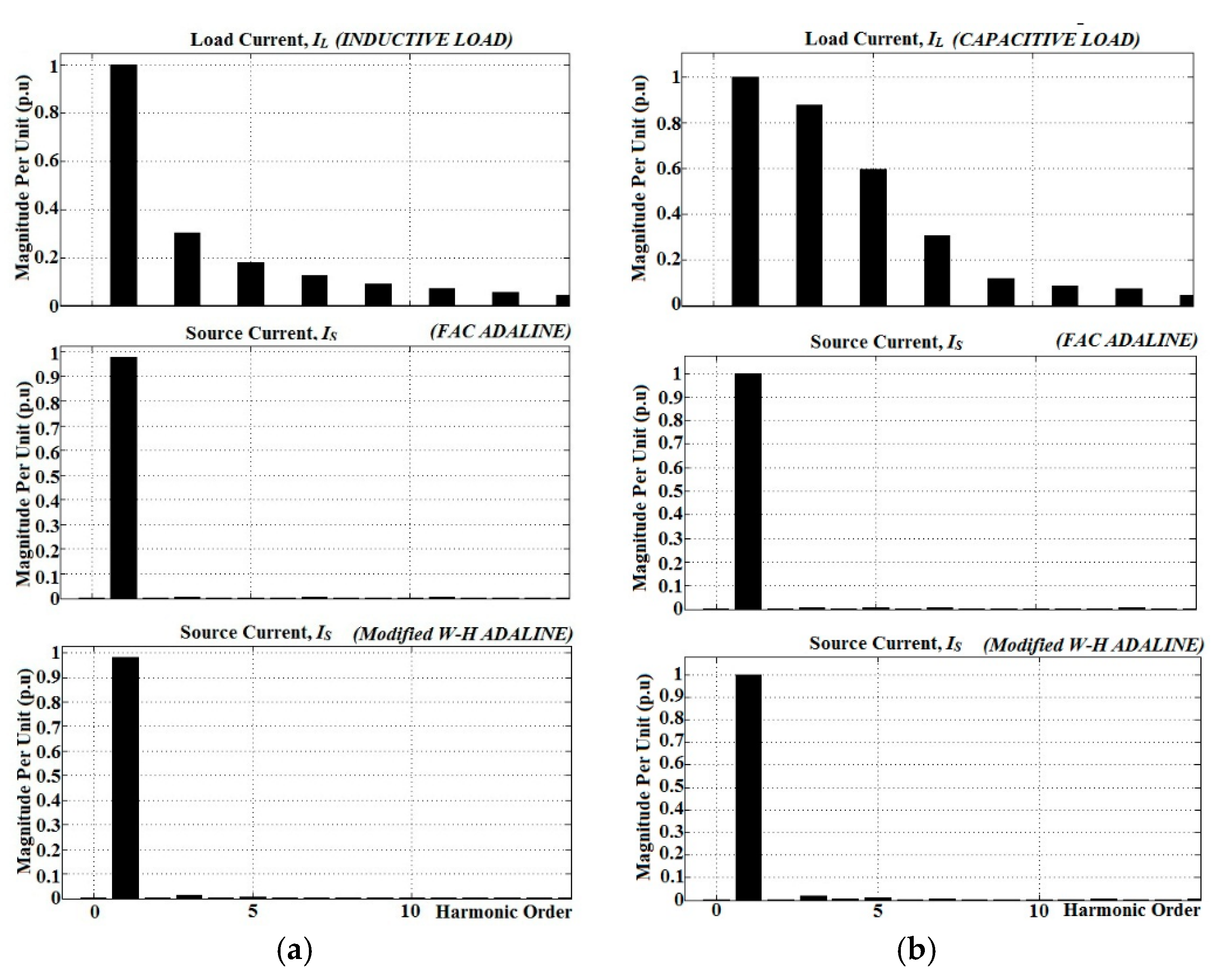
Figure 10 shows harmonics spectrum of the nonlinear loads’ currents and the source currents for operation of SAPF without PV, by using both harmonics extraction algorithms.
Like in the simulation results, by referring to
Figure 7 and
Figure 8, the FAC ADALINE algorithm produces better THD values for both dynamic operations. Very good elimination for all harmonic orders is shown in
Figure 10, especially with the proposed algorithm. The source current is also in phase with the source voltage. Without PV, THD values obtained are 2.3% for inductive load and 2.8% for capacitive load, whereas by using the existing algorithm, THD values are only 3.1% for inductive load and 3.7% for capacitive load. When the PV system is operated at 200 W/m
2, the proposed algorithm produces THD values of 2.54% for inductive load and 3.15% for capacitive load, and meanwhile, the existing algorithm produces higher THD values of 3.2% for inductive load and 3.91% for capacitive load. During irradiance at 600 W/m
2, the proposed algorithm clearly produces lower THD values of 2.8% for inductive load and 3.32% for capacitive load, as compared to the existing algorithm with 3.75% and 4.2% for inductive and capacitive loads respectively. Lastly, for irradiance at 1000 W/m
2, the proposed algorithm produces THD values of 3.2% and 3.76% for inductive and capacitive loads respectively. The existing algorithm meanwhile produces THD values of 4.12% for inductive load and 4.52% for capacitive load.
Table 7 summarizes the overall experimental results of THD for both harmonics extraction algorithms with both nonlinear loads under multiple irradiances.
The active powers from the source grid during PV in off condition (0 W/m2) for inductive and capacitive loads are 450 W and 380 W, respectively. Meanwhile, load powers are 382 W for the inductive load and 323 W for capacitive load. Balanced active powers of 68 W and 57 W for inductive and capacitive loads are absorbed by SAPF. The reactive powers produced by using the proposed algorithm are 64 VAR for inductive load and 54 VAR for capacitive load. By using the existing algorithm, the reactive powers of the SAPF are 60 VAR for inductive load and 49 VAR for capacitive load. As obtained in the simulation work, higher reactive powers produced by the proposed algorithm shows its better performance of compensation.
By referring to
Figure 7 and
Figure 8, the proposed algorithm achieves higher source power reduction than the existing algorithm for both nonlinear loads with three different irradiances. When the PV is in on condition at 200 W/m
2, the proposed algorithm achieves a source power reduction of about 23 W (4.7%) for inductive load and 16 W (4.3%) for capacitive load, and meanwhile, the existing algorithm only achieves 20 W (4.2%) reduction for inductive load and 14 W (3.8%) reduction for capacitive load. At 600 W/m
2, the proposed algorithm reduces the source power to about 66 W (13.8%) and 48 W (12.5%) for inductive and capacitive loads respectively, while the existing algorithm only reduces 63 W (13.2%) and 45 W (11.9%) for inductive and capacitive loads respectively. Lastly, at 1000 W/m
2, the proposed algorithm achieves source power reduction in about 110 W (23.1%) for inductive load and 82 W (21.5%) for capacitive load. The existing algorithm meanwhile just reduces the source power in about 108 W (22.5%) and 79 W (20.8%) for inductive and capacitive loads, respectively.
Table 8 and
Table 9 show details of the experimental results for active powers including load power, source power and source power reduction using both harmonics extraction algorithms for each nonlinear load.
Table 10 provides detailed comparison of percentage of the source power reduction for both algorithms with capacitive and inductive loads. Subsequently, both results from THD value and percentage of source power reduction show significant correlation. Lower THD value contributes to lower power required from the grid as clearly achieved by the proposed algorithm.
For the response time of the harmonics extraction algorithms one can be refer to
Figure 7 and
Figure 8, where during the first dynamic operation, the proposed algorithm shows faster response time for both nonlinear loads, with only 20 ms taken to respond to the change due to the PV being turned on. The existing algorithm needs 40 ms, which is 20 ms delay. The same goes for the second dynamic operation where the proposed algorithm shows faster response time for both nonlinear loads with also 20 ms to respond from low to high irradiance, whereas the existing algorithm takes 40 ms. For the performance under change of nonlinear loads, by referring to
Figure 9, the proposed algorithm shows a faster response time (20 ms) as compared to the existing algorithm (40 ms).
Figure 11 shows the performances of the dc link capacitor, and there are negligible overshoots for the capacitor voltage with a response time of 0.3 s, and for both extraction harmonics algorithms, no difference is observed, which verifies they are not affected to perform their roles. With faster response time, and also higher power reduction and better THD value, the FAC ADALINE algorithm has clearly shown its better performance as a harmonic extraction algorithm in SAPF as compared to the Modified W-H ADALINE algorithm.


 ,
, 


