
A Large Scale Daylighting System Based on a Stepped Thickness Waveguide


Department of Information and Communication Engineering, Myongji University, San 38-2 Nam-dong, Yongin 449728, Korea
*
Author to whom correspondence should be addressed.
Energies 2016, 9(2), 71; https://doi.org/10.3390/en9020071
Submission received: 2 November 2015
/
Revised: 16 December 2015
/
Accepted: 14 January 2016
/
Published: 26 January 2016
Abstract
:This paper presents a study on the use of optical fiber and a solar concentrator for a building daylighting system. Daylighting is essential for improving indoor environments and reducing electric lighting power consumption in office buildings. Traditionally, optical fiber daylighting systems were implemented only on a small scale. More complicated technologies are required for more amounts of daylight over further distance via a smaller light guider. The proposed solar lighting system with optical fiber is composed of an array of linear Fresnel lenses and a stepped thickness waveguide. The linear Fresnel lenses collect light into the stepped thickness waveguide. The stepped-thickness waveguide is an optical component which redirects focused sunlight from the vertical direction to the horizontal direction, and it guides light to the attached optical fiber. Simulation models were developed using commercial optical simulation tools (LightTools™). The optical efficiency and angular tolerance of the system are analyzed. The overall system cost is also estimated. Some considerations on the economic expansion of the system in terms of efficiency and estimated annual average energy saving are discussed. The results show that the presented optical fiber daylighting system is a strong candidate for low-price and highly efficient solution for solar energy application to building energy savings.
1. Introduction
Lighting is an important part of the total living or working environment. The use of electric lighting in a building makes up a significant proportion of the electric energy consumption [1]. In commercial buildings, 40% to 50% of energy consumption is accounted for by artificial lighting [2,3]. As a form of green energy, daylighting is essential for improving environments and reducing the electric lighting power consumption in office buildings [4]. Recently, many researchers have been concentrating on the development of cost effective solutions to the problems associated with designing an integrated, energy efficient and functional daylighting system. Optical fiber daylighting technology is one of the most efficient solutions for the delivery of natural light to a space in a building where daylight is limited. This technology uses large area optical components to collect direct sunlight and then transfers the light to interiors through optical fiber which has the ability to bring sunlight much deeper into buildings [1,5,6,7,8]. In comparison with other existing daylighting technologies such as conventional side and top glass window [9], glazing system [10], and passive tubular daylight guidance system [11], the optical fiber daylighting technologies also decreases heating, ventilation and air conditioning (HVAC) cost because they generate no heat. Efficient daylight buildings are estimated to reduce the energy consumption needed for electric lighting by 50% to 80% [12]. In terms of health, artificial light fails to produce a comfortable indoor environment. Daylight can be used to reduce the impact of illnesses such as seasonal affective disorder and to improve worker productivity [13]. Optical fiber daylighting systems are composed of three main components: the sunlight collector with a Sun tracking mechanism, optical fibers, and luminaires that distribute light in the required space [7]. At the heart of the optical fiber daylighting system is the sunlight collector and the Sun tracking system. Through the research and development of many public and private groups, two basic collector designs have proven to be the most effective and reliable. The first strategy uses optical lenses to refract and concentrate sunlight into optical fibers; the second design captures incoming light by reflection from parabolic mirrors [1,5,7]. However, both designs suffer from the non-uniformity of the light beam over the endface of the optical fibers, and additional secondary optics are needed to homogenize the sunlight and increase the optical fiber coupling efficiency and the tracking tolerance. Traditionally, optical fiber daylighting systems have been implemented only on a small scale. For scaling up a daylighting system, a large number of concentrators are needed to focus the light into the optical fiber bundles. However, such a system becomes costly when the number of sunlight capturing modules must be increased.
In this paper, we introduce an alternative approach for large scale sunlight concentration by replacing the multiple secondary optics and their associated optical fiber coupling modules with a multimode waveguide connected to a shared optical fiber coupling module [14,15,16,17]. The utilization of a waveguide as a solar concentrator is quite new, and originally came from the design of a planar concentrator [18] combined with backlighting [19]. In this case, the sunlight, concentrated by an array of lenses, was coupled into a slab waveguide using specular reflections from an associate area of prism facets fabricated at each lens focus [20]. This approach is able to reduce the complexity of optical fiber daylighting systems through a more robust concentration. Sunlight concentrators using optical waveguides as secondary optics can be classified into two main classes, namely, lossy and lossless systems [15]. On one hand, the lossy systems have planar waveguides which maintain the same modal cross section, so that the length of the planar slabs is unlimited. The first lossy structure proposed by Karp et al. [15] uses round and small micro-structures as secondary optical elements. However, the lossy systems lose some of the collected sunlight that strikes and decouples subsequent directing surfaces. On the other hand, the lossless systems do not have geometrical decoupling losses. The lossless system is a kind of planar solar concentrator of “stepped-shape” that proposed by Moore et al. [21]. The appropriate stepped waveguide design successfully avoids guiding-ray interaction with other injection facets, so that it prevents the ray leakages from the waveguide. The thickness of the waveguide needs to be increased as the light is collected from each subsequent linear Fresnel lens. Therefore, since the thickness of the waveguide is limited, the maximum physical length of the concentrator is also limited. Figure 1 illustrates the differences between two mechanisms: “lossy and lossless”. The lossless systems are limited by length (Figure 1a) and lossy systems are limited by efficiency (Figure 1b).
Figure 1.
(a) Lossless mechanism has no decoupled loss but requires an increase in the waveguide thickness; (b) Lossy mechanism does not require an increase in the waveguide thickness, but decoupling loss occurs at the redirecting surface.
Figure 1.
(a) Lossless mechanism has no decoupled loss but requires an increase in the waveguide thickness; (b) Lossy mechanism does not require an increase in the waveguide thickness, but decoupling loss occurs at the redirecting surface.

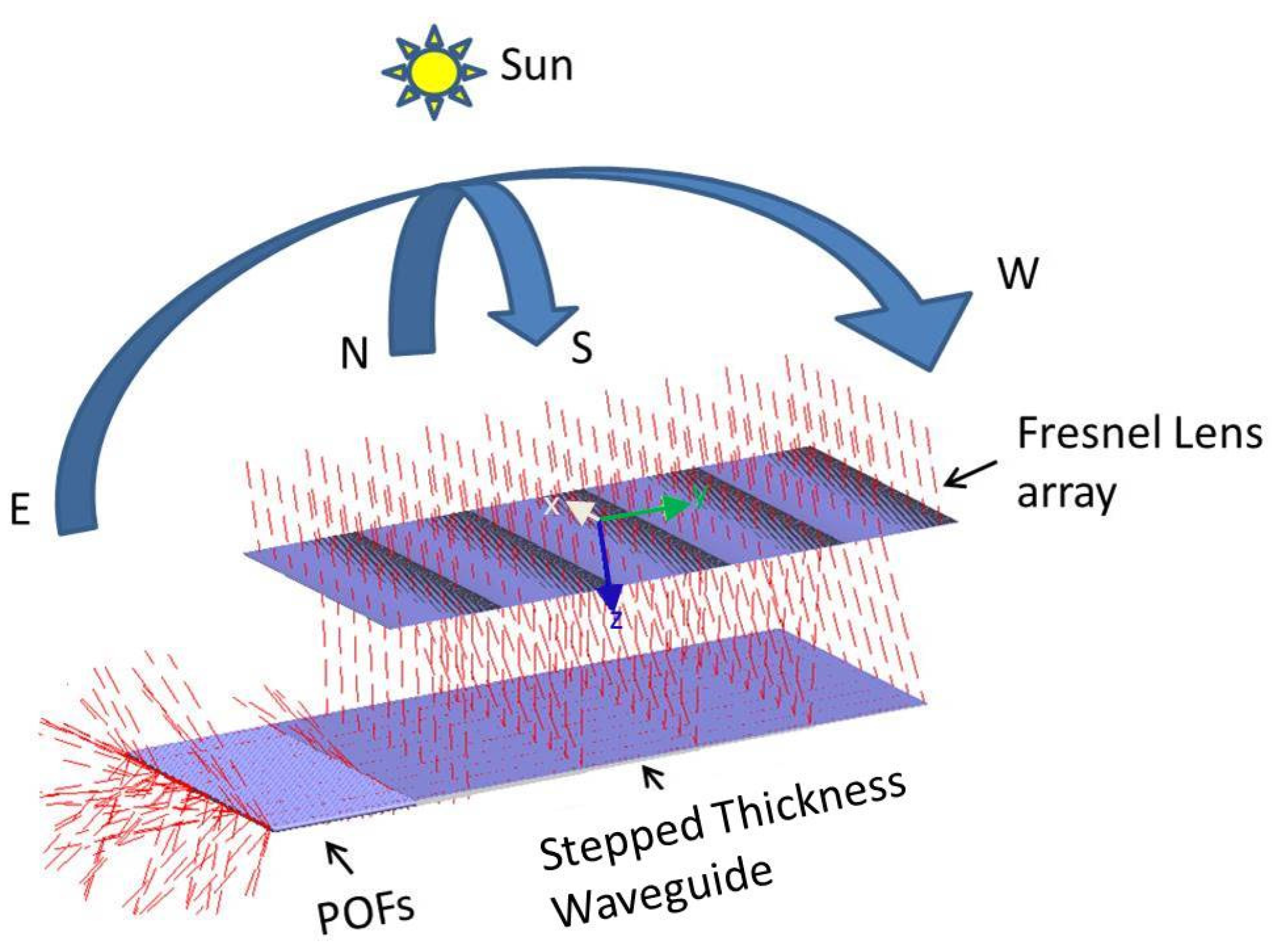
Our goal was to design a large scale sunlight concentrator whose shape is simple and fabrication cost per unit area is very low. Constraining the design to be compatible with an injection molding process, we proposed a novel optical fiber based daylighting system using linear Fresnel lenses and a stepped thickness waveguide (lossless mechanism). The physical layout of the system is shown in Figure 2a. Light focused by each element of the linear Fresnel lens array is reflected and coupled into a stepped thickness waveguide by the light directing surfaces. The light directing surfaces are tilted surface with mirror coating as shown in Figure 2b. Sunlight is propagated within the slab by total internal reflection (TIR) and is guided into a ribbon optical cable placed at the waveguide thicker edge, as shown in Figure 2a.
Figure 2.
(a) Physical layout of optical fiber daylighting system, using linear Fresnel lens array and stepped thickness waveguide; (b) Detail of stepped thickness waveguide from bottom view.
Figure 2.
(a) Physical layout of optical fiber daylighting system, using linear Fresnel lens array and stepped thickness waveguide; (b) Detail of stepped thickness waveguide from bottom view.

The remainder of the paper is organized in the following manner: Section 2 describes the proposed daylighting system using a linear Fresnel lens array and a stepped thickness waveguide. A detailed description of optical fiber coupling is also discussed in this part. In Section 3, the optical fiber daylighting system based on a stepped thickness waveguide is modeled in LightTools™ software (Synopsys Inc., Mountain View, CA, USA) to evaluate the performance of such a system. Finally, brief concluding remarks and possibilities for future work are included in Section 4.
2. Proposed Sunlight Concentrator for Optical Fiber Daylighting System
The design for an optical fiber daylighting system powered by renewable solar energy for indoor illumination is presented in this section. The sunlight concentrator researched in this study is composed of a linear Fresnel lens array and a stepped thickness waveguide. First, we proposed a design for a sunlight concentrator to collect direct sunlight. The concentrator is supposed to be equipped with a tracking system to collect sunlight from the optimum direction [7]. An optical fiber bundle is attached at the exit port of the optical concentrator to transfer the sunlight to the interior. The components of the optical system, the design parameters, and their effects on the optical performance are discussed below in detail.
2.1. Fresnel Lens Array
In conventional optical daylighting systems, the primary concentrators are constructed from several different types of concentrators, such as a glass lens, an array of Fresnel lenses, compound parabolic concentrators (CPC), diffractive concentrators, high reflectivity mirrors, or combinations of lenses and mirrors. Because of the expense and the rapid degradation of quality, conventional glass lenses and high reflectivity mirrors are not recommended for the primary concentrator of a daylighting system. In this study, the primary concentrator is constructed from a one dimensional linear array of Fresnel lenses. For simulation purpose, we used some parameter of a commercial linear Fresnel lenses from Microsharp (Microsharp Corporation Ltd., Oxfordshire, UK) with the performance data as given in Table 1 [22]. A linear Fresnel lens has a micro-structured surface, which consists of a series of grooves with changing angles of slope as the distance from the optical axis increases. A linear Fresnel lens is a non-imaging optical device which can focus light in one direction only, resulting in a narrow line image [23].

| Fresnel Lens Specifications | |
|---|---|
| Focal Length | 300 mm |
| Size | 200 mm × 1000 mm |
| Thickness | 3.5 mm |
| Material | PMMA * |
* PMMA: Polymethyl methacrylate.
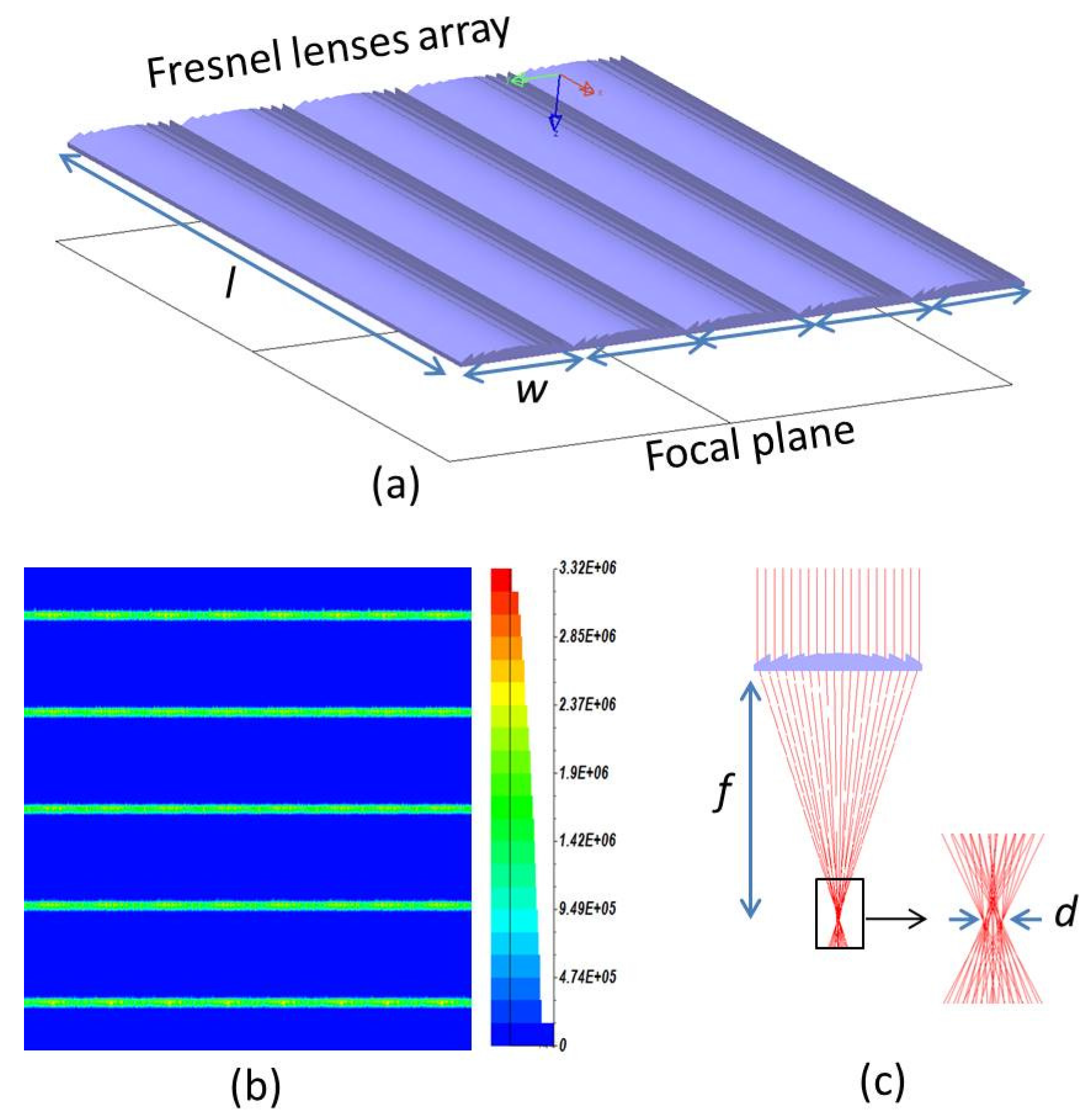
In our optical design and simulations, five Microsharp linear Fresnel lenses, each one width w = 200 mm and length l = 1000 mm, are arranged in linear array as shown in Figure 3a. The focused regions are five parallel lines, which are also arranged in a linear array on the focal plane. However, the Fresnel lenses have several inherent disadvantages [23]. One of them is the dispersion of the solar spectrum. For daylighting systems, the dispersion of the visible range is very important, as this leads to an essential decrease in optical efficiency and the concentration ratio of the system, especially for the Fresnel lens with high concentration. The concentration ratio of primary lenses is calculated by the ratio of the focused area and lenses area. LightTools™ software was used to analyze the dispersion of the visible range. The sunlight source used in the analysis was in the range of 400–750 µm. Figure 3b shows the sunlight distribution on the focal plane. Figure 3c illustrates schematically how the sunlight beam passes through a Fresnel lens. It is noted that the dimensions of some specific parts of the system are exaggerated for convenient interpretation. The sunlight is dispersed at the focal plane of the Fresnel lens due to the wavelength dependence on the refractive index of the lens material. We realized that the light was focused from a large area to a thin line with line width of d = 3 mm. The focused area defines the amount of Sun image on the focused region, and this is a design parameter for the directing surfaces and also for the light guide thickness.
Figure 3.
(a) Linear Fresnel lenses array; (b) Light distribution on the focal plane; (c) Ray tracing of sunlight beam passing through a Fresnel lens.
Figure 3.
(a) Linear Fresnel lenses array; (b) Light distribution on the focal plane; (c) Ray tracing of sunlight beam passing through a Fresnel lens.

The focal length of each linear Fresnel lens in the primary concentrator array defines the main thickness of the total structure. In this case, the focal length was f = 300 mm (Table 1). This meant that the thickness of the concentrating module was around 300 mm. Together with the focal length, the aperture of each Fresnel lens element is an important parameter. The f-number of a linear Fresnel lens is the ratio of the lens’s focal length to the width of the lens. For the Microsharp linear Fresnel lenses, the f-number is f/w = 1.5. If the f-number gets smaller, then some light rays coming into the focus become more angled. This angle is an important parameter for the directing surface and should be properly designed to achieve total internal reflection (TIR) at the directing surface and from the walls of the light guide structure [16]. The focused area and the f-number are the most important input parameters for the stepped thickness waveguide which will be discussed below.
2.2. Stepped Thickness Waveguide
The waveguide is responsible for redirecting and transferring the light to the exit port of the concentrator. As shown in Figure 2, this part lies below the primary collecting lens array. The sunlight passes though the linear Fresnel lenses and is coupled into a stepped thickness waveguide using specular reflections from an associated area of mirror facets fabricated at each lens focus. The facets redirect light onto a guide layer. Rays that exceed the critical angle, as defined by Snell’s law, propagate via total internal reflection (TIR) within the waveguide to the exit aperture. TIR is a complete reflection with negligible spectral or polarization-dependent losses enabling long propagation lifetimes [24]. The stepped thickness waveguide also provides excellent beam homogenization when diverging illumination is coupled into a large number of supported modes. Light directing surfaces, light transmitting media, and the exit port of the concentrator are the three main features of the stepped-thickness waveguide structure (Figure 4).
Figure 4.
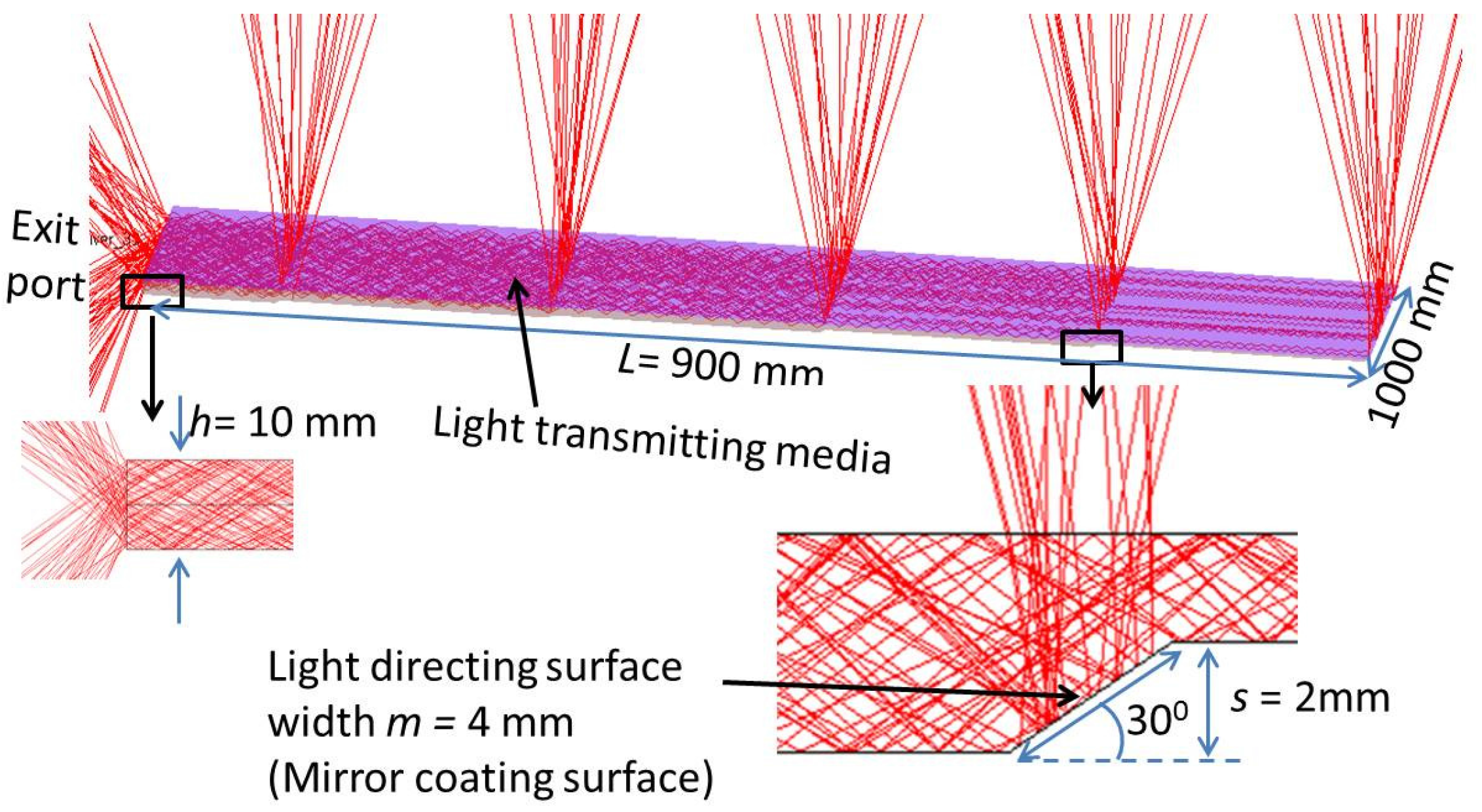
Graphical representation of the stepped thickness waveguide geometry associated with the parameters.
Figure 4.
Graphical representation of the stepped thickness waveguide geometry associated with the parameters.

The stepped thickness waveguide has five steps so that total length becomes L = 900 mm as shown in Figure 4. Light directing surfaces are tilted mirror facets that reflect the light into the waveguide at an angle which satisfies the conditions for TIR. For f-number = 1.5, the surface of the directing mirrors should be at a 30° incline, as shown in Figure 4. Because the thickness of the light focused area of each lens is d = 3 mm, the width of the directing mirror must be larger than 3mm to cover all the sunlight spot, but, increasing the width of the directing mirror increases the thickness of the waveguide, and this results in a reduced concentration ratio for the system. However, reducing the width of light directing mirror will reduce the tracking tolerance of system. In this situation, the appropriate width of the directing mirror is m = 4 mm, and the increasing thickness of one step of the waveguide is s = 2 mm. With m = 4 mm, tolerance of system can adapt with typical commercial Sun tracking system. Detail of system tolerance will be discussed in the part 3.3 of this paper. So the thickness of the end of a stepped-thickness waveguide with five steps becomes h = 5s = 10 mm. In accordance with the arrangement of the proposed solar concentrator, as shown in Figure 2, an important property of the stepped thickness solar concentrator, the geometric concentration ratio, Cgeo, is given by:
The material absorption is also important and it can significantly affect the final efficiency of the system because the L = 900 mm length of the proposed stepped thickness waveguide is quite long. As the light travels a considerably longer distance inside the light guide, absorption by the light guide material becomes important. Therefore, a low absorbing material should be used to fabricate the light guide for the system.
2.3. Plastic Optical Fiber Coupling
The optical fiber consists of a core, cladding, and an external protective coating. The light travels inside the core, while the cladding, which has a lower refractive index, provides internal reflection at the boundary of the core. The optical fibers used in daylighting and solar thermal applications for the transmission of sunlight need to transmit a broad spectrum. One of the most significant features of sunlight transportation is the wiring, and the wiring must be as simple as electrical wiring. Therefore, only optical fibers can fulfill this requirement. Optical fibers were utilized to deliver sunlight to the interior with small losses. Silica optical fibers (SOFs) are known to be good light-transmission media and have the best resistance to heating; however, SOFs are expensive. Plastic optical fibers (POFs) have substantially higher attenuation coefficients than SOFs, but POFs are preferred in daylighting systems due to their lower cost, tighter minimum bend radius, ease of installation and durability for complex wiring in buildings [1,5]. The light can be transferred over long distances without visible changing of the input color because the POFs are made with PMMA, which has attenuation minima of 64, 73 and 130 dB/km, occurring at 520, 570 and 650 nm, respectively. These wavelengths indicate that the PMMA fibers will transmit green, yellow and red light particularly well. In this study, two approaches were proposed for optical coupling, using normal diameter core POFs and very large core POFs. We employ two types of POFs from Anchor Optics for comparison [25]. The POF parameters are listed in Table 2.
| Parameters | Normal Core POF | Very Large Core POF |
|---|---|---|
| Attenuation | 0.45 dB/m | 0.8 dB/m |
| Core/Cladding Diameter | 1.960/2.0 mm | 9.960/10 mm |
| Refractive Index: Core/Cladding | 1.492/1.402 | 1.492/1.402 |
| Minimum Bend Radius | 50 mm | 80 mm |
| Spectral Trans. Range | 380–750 nm | 380–750 nm |
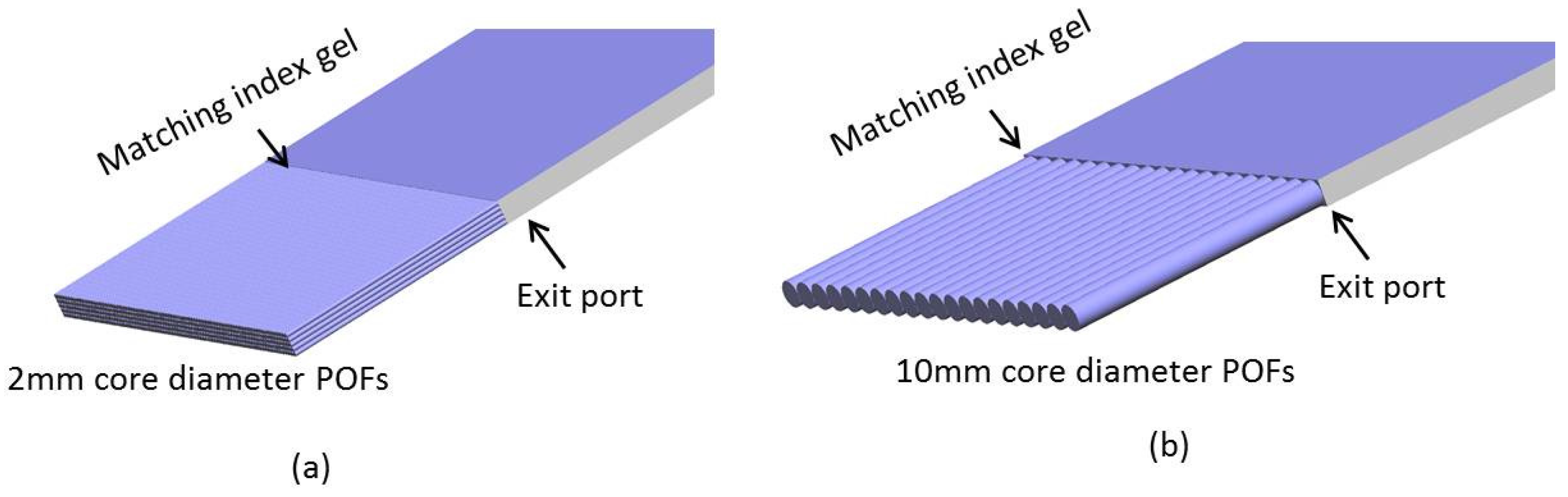
The exit port from the concentrator has a rectangular shape with a size of 10 mm × 1000 mm, so a ribbon configuration of optical fiber is proposed for the optical fiber coupling. For normal POFs with a 2 mm core diameter, 2500 pieces of optical fibers were arranged in a 500 × 5 rectangular array and were grouped together in a ribbon configuration. If the extremely large core POF, with a 10 mm diameter was used, the total number of POFs was reduced to 100 pieces and they were arranged in a 100 × 1 rectangular array. Figure 5a illustrates the optical fiber coupling configuration using the 2 mm core diameter POFs, and Figure 5b shows the 10 mm core diameter POFs. Commonly, multiple optical fibers are simply coupled to the waveguide as tightly as possible after the endfaces of the fibers have been polished. The intensity of the reduction occurs primarily as a result of imperfections in the endface geometry and numerical aperture mismatches as well as Fresnel reflection losses. Fresnel reflection losses occur when light exits the waveguide material and enters an optical fiber medium with a different refractive index, such as air. Fresnel losses are relatively constant, no matter what distance is involved, even when the air gap is microscopically small. To reduce Fresnel losses due to the air gap between the waveguide and the POFs, index matching gel was applied to fill the air gap. In the simulation, the index matching gel is filled between the waveguide and the POFs bundle. Following this, Fresnel losses across the coupling region were reduced significantly. Loss mechanisms are taken into account and discussed in Section 3 in greater detail.
Figure 5.
Illustration for a piece of stepped-thickness waveguide coupled with the ribbon arrangement of (a) 2 mm core diameter POFs; and (b) 10 mm core diameter POFs.
Figure 5.
Illustration for a piece of stepped-thickness waveguide coupled with the ribbon arrangement of (a) 2 mm core diameter POFs; and (b) 10 mm core diameter POFs.

3. Concentrator Simulations and Performance
3.1. Optical Efficiency
Optical modeling plays a crucial role in the efficiency evaluation of an optical system. Commercial optical modeling software, LightTools™, was used to design and simulate the geometrical structure of the stepped-thickness waveguide optical fiber daylighting system. In the system designed, one of the most common optical plastics, poly-methyl methacrylate (PMMA) with refractive index nPMMA = 1.49 was selected for the Fresnel lenses, stepped thickness waveguide and optical fibers. The Fresnel lenses are commercial products from Microsharp, with parameters, as shown in Table 1, and the POFs were from Anchor Optics Ltd. (Barrington, NJ, USA), as shown in Table 2. The coupling region between the exit port of the waveguide and the optical fibers was filled with epoxy as a matching gel with a refractive index of n = 1.51. The simulation for optical efficiency of a sunlight concentrator based on a stepped thickness waveguide was implemented in real scale. An illutration of the structure for the simulation is shown in Figure 6. The optical efficiency, which is simply defined as the ratio of the output luminous flux to the input luminous flux, is a function of the reflection and absorption losses.
Figure 6.
Illutration of the structure for the simulation.

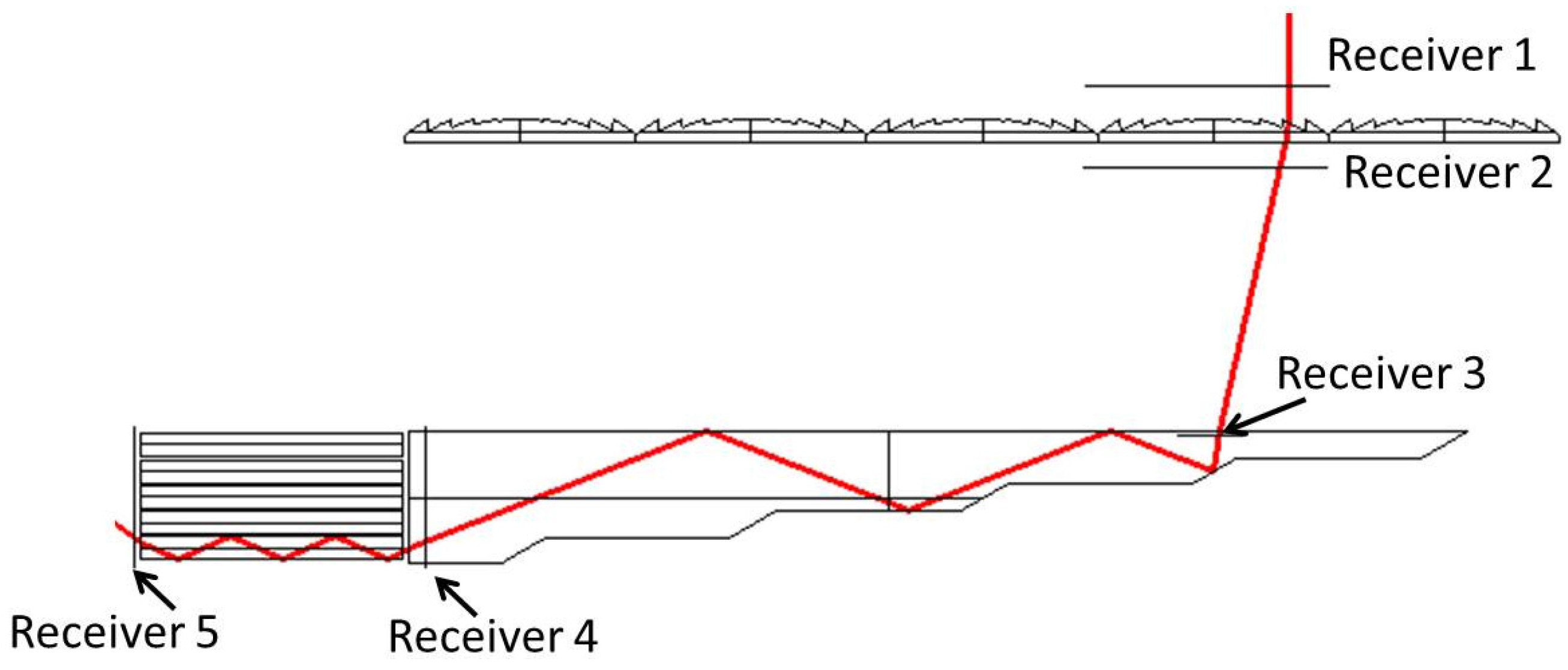
To evaluate the losses in the system, in simulation model, we inserted five optical surface receivers as shown in Figure 7. The Fresnel reflection losses occur at the boundaries where the light passes from one region to another with different refractive indices. In this proposed system, the Fresnel losses occur at the surface of the Fresnel lenses, waveguide and POFs. The major Fresnel losses occur at the Fresnel lens surface and the waveguide surface, and they are denoted by L1 and L2, respectively. Using LighTools™ software, L1 and L2 can be calculated by the Equations (3) and (4), respectively. We found L1 = 4.1% and L2 = 5.3%. The reflection losses from the surface can be reduced by properly designing the AR coating with a multilayer structure, but this is not recommended because the system becomes too costly. The Fresnel loss at the conjunction between POFs and waveguide can be reduced to below 0.1% by filling the matching index and then it can be ignored in comparison with other losses:
The attenuation of the stepped thickness waveguide is also important, and it can significantly affect the final efficiency of the system. Consider a light ray which enters a waveguide of length L and thickness h at position P from the exit aperture: Equation (5) introduces light directing mirror reflection loss r and attenuation by the exponential decay of the path length multiplied by the attenuation coefficient α [15]:
Here, P is distance from each light directing mirror to the exit port, and w is the linear Fresnel lens width. A stepped thickness waveguide with a commonly used optical pure plastic material has attenuation coefficient α = 1.8 × 10⁻² dB/m. For a large scale daylighting system, the light travels considerably longer distances inside the waveguide, and the attenuation by the light guide material becomes more important. In case of scaling up the system, the system size is limited by this kind of loss. By simulation, the loss inside the waveguide is calculated by Equation (6). In our design, the light guide has a total attenuation of L3 = 1.78% on the average:
The numerical aperture mismatch between the optical fiber and the stepped index waveguide also causes significant losses. The optical fiber and the stepped thickness waveguide in this case have a maximum acceptance angle θ, given in the following relationship:
where, and are the refractive indices of the core and cladding, respectively as shown in Table 2; is the refractive index of matching gel. By taking the values in Table 2, we can find that the acceptance angle of plastic optical fiber is θ = ± 19°. The input angle of light to optical fibers from the exit port of the waveguide can be calculated based on the numerical aperture of the waveguide. From Equation (7), with a low index of 1.00 (the index of air) and a high index of 1.49 (index of PMMA), the angle of the sunlight rays that escape from the waveguide exit port are in the range of ± 49°. Only the rays of the output beam that have an angle of less than ± 30 degrees (the numerical aperture of optical fiber), can be coupled to the optical fibers. The geometrical POF coupling efficiency is calculated by the ratio of the cross section area of the optical fiber ribbon and the exit port area, which is given by ηgeo-coupling = 0.75. Equation (8) shows the optical fiber coupling loss calculation in the simulation. We found the POFs coupling loss to be L4 = 36.76%:
With the system parameters given above, the system efficiency is found to be 56.4%, including attenuation, reflection, geometrical mismatch and optical fiber coupling losses.
Figure 7.
Illustration of the simulation structure for loss analysis and single ray-tracing analysis for design verification.
Figure 7.
Illustration of the simulation structure for loss analysis and single ray-tracing analysis for design verification.

3.2. Daylighting
The illuminance from the sunlight was measured at different times of the day. The site of application was located at 127° longitude and 37.5° latitude. Here we will look at the illuminance on a summer day as an example: The highest solar elevation (zenith) angle at the site is 76°, and the time is set for 12:30 PM. To achieve direct sunlight, we assume that the daylighting system has a Sun tracking device which rotates the concentrator module toward the Sun all day. The area of the sunlight collector is 1 m2 because the concentrator module is the array of five linear Fresnel lenses with size of 0.2 m × 1 m. The conversion into luminous flux in lumens can be calculated by:
where E is measured illuminance, S is the area of sunlight concentrator, and F is the input luminous flux on the surface of sunlight collector. With Equation (10), we calculated the input luminous flux on surface of sunlight concentrator from the measured illuminance outdoor. We then use the input luminous flux to calculate total luminous flux at the output of concentrator. The measured illuminances of the input flux at the surface of the concentrator F and of the luminous flux at the output concentrator are listed in Table 3.
Every optical daylighting system is utilized to guide light deep into a building, therefore, the transmission loss of POF should be included in the calculation. If we assume that the daylight capturing system is placed on the top of a building to illuminate a room at 6 m depth inside the building, roughly 10 m of POF length will be needed from the capturing point to the distribution area. The total length of the optical fiber will be around 25,000 m if we utilize 2 mm core diameter POFs. In case of using the extremely large core POF, the total length will be 1000 m. The cost of the POFs are about $0.5/meter for the 2 mm core POFs, and $6/meter for the 10 mm core POFs [25]. The total cost for 25,000 m of the 2 mm core diameter POFs is two times larger than the total cost for 1000 m of the 10 mm core diameter POFs. However, the 10 mm core diameter POF has a transmission loss of 0.8 dB/m while the transmission loss of the 2 mm core diameter is only 0.46 dB/m. This means that the light flux will decrease by 2.8 and 6.3 times, respectively, when it propagates along 10 m of either the 2 mm or 10 mm core diameter POFs. The luminous flux for the illumination in the interior when using the 2 mm core diameter POFs and the 10 mm core diameter POFs are shown in two last columns of Table 3. Finally, the diameter core of the POF should be chosen depending on both cost-effectiveness and efficiency.
Table 3.
Average illuminance at different times of the day and calculated luminous flux at the interior for the proposed system.
| Time | Solar Altitude (°) | Sunlight Illuminance (lux) | Luminous Flux on the Surface Concentrator (lm) | Luminous Flux at the Output of Concentrator (lm) | Illumination in the Interior (lm) (Using10 m of 2 mm Diameter POFs) | Illumination in the Interior (lm) (Using 10 m of 10 mm Diameter POFs) |
|---|---|---|---|---|---|---|
| 6 AM | 8 | 20,000 | 20,000 | 11,280 | 4028 | 1790 |
| 7 AM | 19 | 40,000 | 40,000 | 22,560 | 8057 | 3580 |
| 8 AM | 31 | 60,000 | 60,000 | 33,840 | 12085 | 5371 |
| 9 AM | 43 | 80,000 | 80,000 | 45,120 | 16114 | 7161 |
| 10 AM | 54 | 100,000 | 100,000 | 56,400 | 20142 | 8952 |
| 11 AM | 65 | 105,000 | 105,000 | 59,220 | 21150 | 9400 |
| 12 PM | 74 | 110,000 | 110,000 | 62,040 | 22157 | 9847 |
3.3. Tolerance of the System
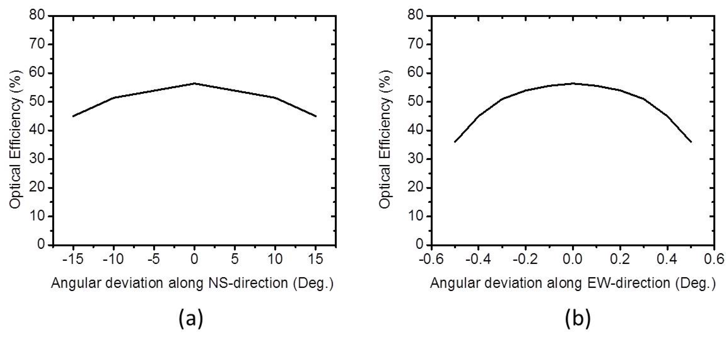
For proper operation of the proposed optical fiber daylighting system, direct sunlight should always be focused into the center of the directing mirror facets in the stepped thickness waveguide. This is a difficult task since the position of the Sun is always changing, and this led us to use a Sun tracking system. The required accuracy of the Sun tracking system is determined by the solar concentrating collector’s angle of tolerance. The tolerance of the system is the acceptable angular deviation of the sunlight direction from the two main axes of the system, within the allowable efficiency loss. It is defined as the angle where the efficiency drops by 10%. The acceptance angle determines the required accuracy of the tracking system mounted upon the concentrator [14]. The dependence of the optical efficiency of the system on angular deviation along the North-South (NS) and East-West (ES) direction are very different because the system is not symetric. We examined the efficiency with different angular deviations of the sunlight direction along the NS and EW directions. The alignment of system along NS and EW direction was shown in Figure 6. Figure 8a shows the optical efficiency output relative to angular deviation along the NS direction, and Figure 8b shows a graph of effciency versus angular deviation along the EW-direction. The simulation results show that the tolerance is more than ±15 degrees along the NS-direction, which is far larger than that for the EW-direction (±0.5°). This indicates that by using a line focusing linear Fresnel lens array as the primary concentrator, the acceptance angle along the NS-direction can be greatly increased without sacrificing too much optical efficiency. Therefore, the proposed system uses a linear Fresnel lens array instead of a conventional lens array, as the primary concentrator can lower the accuracy requirements along the NS-direction, and this reduces the cost of the tracking system [14]. As the size of each stepped waveguide becomes larger, the focused light from the primary lens can be transferred more effectively to the waveguide without being decoupled. A volumetric increase of the light waveguide while keeping the primary concentrator the same, gives better tracking tolerance along the NS-direction. But increasing the acceptance angle reduces the concentration ratio dramatically [16]. Therefore, in the system design, the tolerance and the concentration should be kept in balance.
Figure 8.
Variation of optical efficiency of concentrator at different angular deviations along the (a) NS-direction and (b) EW-direction.
Figure 8.
Variation of optical efficiency of concentrator at different angular deviations along the (a) NS-direction and (b) EW-direction.

4. Discussion
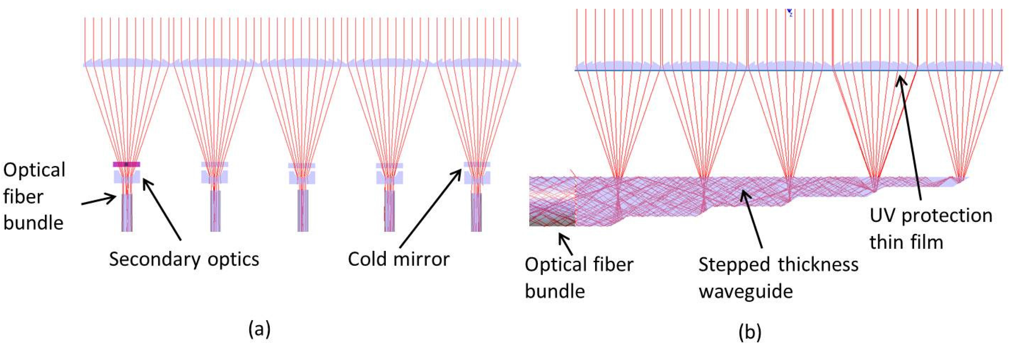
Optical fiber daylighting systems are concerned more about delivering daylight into remote and windowless spaces in buildings. Many types of optical fiber daylighting systems have been developed with various technologies and solutions over a few decades, but few of them has been successfully commercialized. Providing a cost effective system is the major challenge for optical fiber daylighting system. The concentrator parts of typical optical fiber daylighting systems consist of a large primary optical component to focus sunlight and a secondary optical element for flux collimation. The requirement for the alignment between the primary optics, secondary optics and optical fiber bundles is very tight. Scaling up the system will increase the number of secondary optics and optical fiber bundles. The primary purpose of the present work is to find a low cost and highly efficient way to utilize the solar energy for daylighting. In this research, we proposed a cost-effective and large scale approach for an optical fiber daylighting system using non-imaging optic devices such as an array of linear Fresnel lenses and a stepped-thickness waveguide as a concentrator. The primary collector is consisted of a large linear Fresnel lens array. The secondary optical devices were replaced by one stepped thickness waveguide. All optical fiber bundles were also grouped into one. Figure 9 shows the differences between conventional system using individual secondary optics and our proposed system using a common stepped thickness waveguide. Much less number of optical components reduces complexity and cost concerns. The optical alignment became simpler since optical fiber bundle was cemented to the waveguide edge.
Figure 9.
(a) Conventional optical daylighting system requires multiple secondary optics and optical fiber bundles; (b) Our proposed system transports sunlight from all apertures to a single optical fiber bundles.
Figure 9.
(a) Conventional optical daylighting system requires multiple secondary optics and optical fiber bundles; (b) Our proposed system transports sunlight from all apertures to a single optical fiber bundles.

The system cost also depends on the price of the optical materials. In our proposed system, glass components such as mirrors, lenses and optical fibers were replaced by plastic materials so that the cost of the system is reduced a lot. The price of Fresnel lenses is more than ten times cheaper than that of the glass mirrors/lenses. The POF costs are as low as one-fifth of the glass fiber costs. It is clear that losses in POFs are much higher than those in silica optical fibers. However, at short fiber distance (less than 100 m), POFs provide acceptable loss and this amount of loss does not affect much on the quality of light for daylighting purpose. The degradation due to ultraviolet (UV) radiation and temperature is also a problem in plastic material. We suggested using UV protection thin film underneath Fresnel lens array to eliminate the UV wavelength [26,27] as shown in Figure 9b. The cold mirrors and spectrally selective optical materials like UV protection films are being widely used in the daylighting technologies. The heat produced due to IR will be spread all over the area of stepped thickness waveguide, therefore it does not affect to POFs. The tolerance of the system was examined in the Section 3.3. The angular acceptance along EW direction was ±0.5° so that we can use typical Sun tracking system whose tolerance is lower than ±0.2° [28]. Very high acceptance angle along NS-direction allows replacement of a Sun tracking system with a seasonal tilting solar system as a cost-effective solution [29]. Seasonal tilting solar system is a step adjustment system that can be adjusted in increments from 0, 10, 20, 30, 40, & 55 degrees.
For an estimate of the cost of whole proposed optical fiber daylighting system, we make the following considerations: the costs of array of Fresnel lenses of 1 m × 1 m size, the stepped thickness waveguide, and mechanical bracket are roughly $200, $100, and $200, respectively. The UV film is about $300. The costs of 5 m long POF bundles whose core diameters are 2 mm and 10 mm are $6250 and $3000, respectively. Automatic single axis Sun tracking system has cost of $300 and seasonal tilt solar system is $100, roughly. Total expected cost of the proposed system is $7450 for 2 mm diameter POFs or $4200 for 10 mm diameter POFs. We can evaluate our proposed system in terms of daylight collection capability and cost effectiveness by comparing our system with two other commercialized systems: Himawari and Parans systems. Due to variety of operating conditions, system comparison is not easy, however we used the data from developers’ publication so that we can estimate our proposed system. The Himawari system collects and concentrates sunlight using multiple Sun tracking Fresnel lenses. Light is transported by quarts optical fibers. The total luminous flux of a Himawari system is 4000 lm which was measured under direct Sun illuminance of about 100,000 lux. The net price of a Himawari system package (including 12 lens collector, two 5 m optical bundles) is $6240 [30]. The Swedish Parans system consists of an array of Fresnel lenses which simultaneously tracks and concentrates daylight. Paran system’s total output flux is about 3540 lm, which was measured under direct Sun illuminance of 100,000 lux, 10 m away from the collector. Parans systems package (six 5 m-optical fiber bundles) net price is about $5425 [31]. The comparisons associated with the daylight collection capability and cost have been summarized in Table 4. As shown in the table, our proposed system can provide 2 to 5 times more output flux than the other previous systems.
Table 4.
Comparison in cost and daylight collection capability with some commercialized optical fiber daylighting systems.
| Comparison Categories | Proposed System | Himawari System | Parans System | |
|---|---|---|---|---|
| 2 mm Diameter POFs | 10 mm Diameter POFs | |||
| Output flux (lm) | 20,142 | 8951 | 4000 | 3540 |
| Cost ($) | 7450 | 4200 | 6240 | 5425 |
Table 5 shows an economic comparison between the proposed system for daylighting of commercial buildings and the traditional lighting system made of a series of fluorescent lamps. Let’s assume we want to provide light to a room with floor area of 50 m2 with a required luminance of 500 lux, thus requiring a total luminous flux of 25,000 lm. The luminous efficiency of fluorescent lamps is about 60 lm/W [32]. By taking account of an average luminous efficiency of solar radiation of 120 lm/W, 1 W of solar radiation is equivalent to 2 W of electricity power in term of lamination. In Seoul—South Korea climate context, the available yearly averaged solar radiation is 3.6 KWh/m2/day (13.0 MJ/m2/day) [33]. The overall light transmission efficiency (sunlight concentrator & 10 m of POFs bundles), defined as the ratio of the delivered luminous flux to the flux incident on the collection surface, equal to 0.201. Table 5 shows that using proposed daylighting system can save 28.68% of electric power consumption for illumination.
Table 5.
Economic comparison with using of fluorescent lamps and saving considerations by daylighting.
| Fluorescent Lamps | ||
|---|---|---|
| Selected room area | 50 | m2 |
| Selected lumen of illuminance | 500 | lux |
| Luminous flux | 25,000 | lm |
| Lamps power | 60 | W |
| Lamps efficiency | 60 | lm/W |
| Luminous flux for each lamp | 3600 | lm |
| Number of lamps to light | 7 | |
| Working hours | 10 | hours/day |
| Working days | 320 | days/year |
| kWh per year | 1613 | KWh/year |
| Korean average cost per kWh | 0.4 | $/KWh |
| Total cost for lighting by fluorescent lamps | 645 | $/year |
| Solar Lighting by Proposed System | ||
| Average solar irradiation in Seoul | 3.6 | KWh/m2/day |
| Electrical power equivalent (lighting purpose) | 7.2 | KWh/m2/day |
| Sun light collection area | 1 | m2 |
| Overall light transmission efficiency | 20.1 | % |
| Collected electrical power per year | 463 | KWh |
| Daylighting money savings | 185 | $ |
5. Conclusions
A large scale optical fiber daylighting system using a stepped thickness waveguide has been designed and discussed with the purpose of saving the energy consumed by electric lighting. To explore the practical performance of the proposed system, a sample optical system was modeled and simulated with LightTools™. The simulation results indicate that 56.4% of optical efficiency was achieved at Cgeo = 100 for the proposed concentrator system. In addition, the tolerance (acceptance angles) in the NS- and the EW-directions also were analyzed. By using a line focusing linear Fresnel lens array as the primary concentrator, an acceptance angle of ±15° was achieved in the NS-direction. This allows us to use a lower accuracy Sun tracking system, such as a passive Sun tracking system along the NS-direction as a cost effective solution. This study is the first to use a stepped thickness waveguide and linear Fresnel lens array for an optical fiber daylighting system. The proposed system is very suitable for large scale building interiors. It shows great potential for the commercial and industrial scale daylighting field. In the future, we will try to implement experimentation under real conditions to verifying the accuracy of the simulation and the commercial viability of the system.
Acknowledgments
This work was supported by a National Research Foundation of Korea (NRF) grant funded by the Korea government (MSIP) (No. 2014R1A2A1A11051888).
Author Contributions
Ngoc Hai Vu and Seoyong Shin conceived and developed the original ideas. Ngoc Hai Vu carried out the performance analysis and simulations, and wrote the paper. Seoyong Shin supervised the research and finalized the paper.
Conflicts of Interest
The authors declare no conflict of interest.
References
- Ullah, I.; Shin, S. Highly concentrated optical fiber-based daylighting systems for multi-floor office buildings. Energy Build. 2014, 72, 246–261. [Google Scholar] [CrossRef]
- Osso, A.; Gottfried, D.; Walsh, T.; Simon, L. Sustainable Building Technical Manual; Public Technol. Inc.: New York, NY, USA, 1996; p. 292. [Google Scholar]
- Martirano, L.A. Smart lighting control to save energy. In Proceedings of the 2011 IEEE 6th International Conference on Intelligent Data Acquisition and Advanced Computing Systems (IDAACS), Prague, Czech, 15–17 September 2011; pp. 132–138.
- Conti, J. Annual Energy Outlook 2012; U.S. Energy Information Administration (EIA): Washington, DC, USA, 2012.
- Han, H.J.; Riffat, S.B.; Lim, S.H.; Oh, S.J. Fiber optic solar lighting: Functional competitiveness and potential. Sol. Energy 2013, 94, 86–101. [Google Scholar] [CrossRef]
- Song, J.; Zhu, Y.; Jin, Z.; Yang, Y. Daylighting system via fibers based on two-stage sun-tracking model. Sol. Energy 2014, 108, 331–339. [Google Scholar] [CrossRef]
- Tsuei, C.-H.; Sun, W.-S.; Kuo, C.-C. Hybrid sunlight/LED illumination and renewable solar energy saving concepts for indoor lighting. Opt. Express 2010, 18, A640–A653. [Google Scholar] [CrossRef] [PubMed]
- Whang, A.J.-W.; Chen, Y.-Y.; Yang, S.-H.; Pan, P.-H.; Chou, K.-H.; Lee, Y.-C.; Lee, Z.-Y.; Chen, C.-A.; Chen, C.-N. Natural light illumination system. Appl. Opt. 2010, 49, 6789–6801. [Google Scholar] [CrossRef] [PubMed]
- Macrelli, G. Electrochromic windows. Renew. Energy 1998, 15, 306–311. [Google Scholar] [CrossRef]
- Schultz, J.M.; Jensen, K.I.; Kristiansen, F.H. Super insulating aerogel glazing. Sol. Energy Mater. Sol. Cells 2005, 89, 275–285. [Google Scholar] [CrossRef]
- Carter, D.J. Developments in tubular daylight guidance systems. Build. Res. Inf. 2004, 32, 220–234. [Google Scholar] [CrossRef]
- Green building rating systems-draft recommendations for a U.S. rating system. In Proceedings of the U.S. Green Building Council, Bethesda, MD, USA, 13 August 1995.
- Marks, F.M. Letter to the Editors: Lighting for Different Healthcare Settings. Health Environ. Res. Des. J. 2013, 6, 166–168. [Google Scholar] [CrossRef]
- Xie, P.; Lin, H.; Liu, Y.; Li, B. Total internal reflection-based planar waveguide solar concentrator with symmetric air prisms as couplers. Opt. Express 2014, 22, A1389–A1398. [Google Scholar] [CrossRef] [PubMed]
- Karp, J.H.; Tremblay, E.J.; Ford, J.E. Planar micro-optic solar concentrator. Opt. Express 2010, 18, 1122–1133. [Google Scholar] [CrossRef] [PubMed]
- Selimoglu, O.; Turan, R. Exploration of the horizontally staggered light guides for high concentration CPV applications. Opt. Express 2012, 20. [Google Scholar] [CrossRef] [PubMed]
- Bouchard, S.; Thibault, S. Planar waveguide concentrator used with a seasonal tracker. Appl. Opt. 2012, 51. [Google Scholar] [CrossRef] [PubMed]
- Chien, M.-C.; Lung Tung, Y.; Tien, C.-H. Ultracompact backlight-reversed concentration optics. Appl. Opt. 2009, 48, 4142–4148. [Google Scholar] [CrossRef] [PubMed]
- Winston, R.; Gordon, J.M. Planar concentrators near the étendue limit. Opt. Lett. 2005, 30, 2617–2619. [Google Scholar] [CrossRef] [PubMed]
- Karp, J.; Tremblay, E.; Hallas, M.; Ford, J. Orthogonal and secondary concentration in planar micro-optic solar collectors. Opt. Express 2011, 19, 673–685. [Google Scholar] [CrossRef] [PubMed]
- Moore, D.; Schmidt, G.; Unger, B. Concentrated photovoltaics stepped planar light guide. In Proceedings of the International Optical Design Conference 2010, Jackson Hole, WY, USA, 13–17 June 2010.
- Microsharp Datasheet. Linear Fresenl Lenses. Available online: http://www.microsharp.co.uk/index.php/products/162-linear-fresenl-lenses-.html (accessed on 8 October 2015).
- Jing, L.; Liu, H.; Wang, Y.; Xu, W.; Zhang, H.; Lu, Z. Design and Optimization of Fresnel Lens for High Concentration Photovoltaic System. Int. J. Photoenergy 2014, 2014, 1–7. [Google Scholar] [CrossRef]
- Balanis, C.A. Advanced Engineering Electromagnetics; Wiley: New York, NY, USA, 1989; Volume 52. [Google Scholar]
- Plastic Optical Fibers. Available online: http://www.anchoroptics.com/catalog/product.cfm?id=354 (accessed on 8 October 2015).
- Sapia, C. Daylighting in buildings: Developments of sunlight addressing by optical fiber. Sol. Energy 2013, 89, 113–121. [Google Scholar] [CrossRef]
- Mayhoub, M.S. Innovative daylighting systems’ challenges: A critical study. Energy Build. 2014, 80, 394–405. [Google Scholar] [CrossRef]
- Lee, C.; Chou, P.; Chiang, C.; Lin, C. Sun tracking systems: A review. Sensors 2009, 9, 3875–3890. [Google Scholar] [CrossRef] [PubMed]
- Seasonal Tilt Solar Systems. Available online: http://www.solarelectricworks.com/seasonal-tilt-solar-systems/ (accessed on 12 December 2015).
- HIMAWARI Solar Lighting System. Available online: http://www.himawari-net.co.jp/e_page-index01.html (accessed on 12 December 2015).
- PARANS Product Information. Available online: http://www.parans.com/eng/sp3/ (accessed on 14 December 2015).
- Li, T.; Yang, F.; Yuan, C. A novel parabolic trough solar lighting and thermal system for building energy efficiency. In Proceedings of the Automation Science and Engineering (CASE), 2013 IEEE International Conference, Madison, WI, USA, 17–20 August 2013; pp. 657–662.
- Na, S.; Baek, S.; Park, J. Daily global solar radiation estimate in the south korea based on geostationary satellite remote sensing. In Proceedings of the 2012 IEEE International Geoscience and Remote Sensing Symposium (IGARSS), Munich, Germany, 22–27 July 2012; pp. 7460–7463.
© 2016 by the authors; licensee MDPI, Basel, Switzerland. This article is an open access article distributed under the terms and conditions of the Creative Commons by Attribution (CC-BY) license (http://creativecommons.org/licenses/by/4.0/).
Share and Cite
MDPI and ACS Style
Vu, N.H.; Shin, S. A Large Scale Daylighting System Based on a Stepped Thickness Waveguide. Energies 2016, 9, 71. https://doi.org/10.3390/en9020071
AMA Style
Vu NH, Shin S. A Large Scale Daylighting System Based on a Stepped Thickness Waveguide. Energies. 2016; 9(2):71. https://doi.org/10.3390/en9020071
Chicago/Turabian StyleVu, Ngoc Hai, and Seoyong Shin. 2016. "A Large Scale Daylighting System Based on a Stepped Thickness Waveguide" Energies 9, no. 2: 71. https://doi.org/10.3390/en9020071
Note that from the first issue of 2016, this journal uses article numbers instead of page numbers. See further details here.