
A Back-to-Back 2L-3L Grid Integration of a Marine Current Energy Converter

Abstract
: The paper proposes a back-to-back 2L-3L grid connection topology for a marine current energy converter. A prototype marine current energy converter has been deployed by a research group at Uppsala University. The concept behind the prototype revolves around a fixed pitch vertical axis turbine directly connected to a permanent magnet synchronous generator (PMSG). The proposed grid connection system utilizes a well known and proven two level voltage source converter generator-side combined with a three-level cascaded H-bridge (CHB) multilevel converter grid-side. The multilevel converter brings benefits in terms of efficiency, power quality and DC-link utilization. The system is here presented for a single marine current energy converter but can easily be scaled up for clusters of marine current energy converters. Control schemes for both grid-side and generator-side voltage source converters are presented. The start-up, steady state and dynamic performance of the marine current energy converter are investigated and simulation results are presented in this paper.1. Introduction
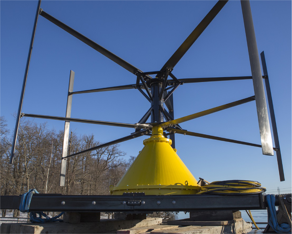
Unregulated rivers, tides and other ocean currents are renewable energy sources with great potential across the globe. One of the big advantages being the high predictability of tidal currents, to within a 98% accuracy [1]. Academic and corporate groups around the world are investigating different concept to convert free flowing water into electricity. Numerous large marine turbine projects with output power above 0.5 MW are presented in [2–4], with several in the pre-commercial stage. Research focusing on converting the power in free flowing water using a vertical axis turbine with a directly driven permanent magnet generator is being conducted by a research group at Uppsala University [5–10]. The concept investigated at Uppsala University uses a cross flow, fixed pitch vertical axis turbine directly connected to a nonesalient permanent magnet generator. Reducing the number of moving parts and an overall low mechanical complexity to reduce the expected need for maintenance is the main idea behind the concept. The generator is placed below the turbine outside of the water flow passing through the turbine. The vertical axis turbine is omnidirectional and can utilize the water flow from any direction perpendicular to the axis of rotation. A first full prototype unit was deployed 2013 in the Dalälv river in the town of Söderfors by the research group at Uppsala University [8]. The prototype, before deployment, is shown in Figure 1.
The work presented here is a step towards grid connection of the prototype and aims to present the system for grid connection. One of the main considarations when choosing this grid connection topologies was the ability to scale it up for much larger converters. A bidirectional topology is chosen as the turbine is not self starting and needs to be accelerated from standstill in order to absorb power from the water. A two-level voltage source converter is placed generator-side and a three-level cascaded H-bridge (CHB) converter connects the system to the grid. This topology is viewed as a good option for connecting one unit and can easily be adapted to a cluster of turbines all connected to the same DC-link. In a future farm the three level inverter can be used to connect the whole farm to the grid with each individual turbine connected to the common DC-link through a two level active rectifier. The reduction in output filter size due to the reduction in harmonics is seen as important especially if the farm is connected to a marine substation where space is greatly limited. The work explores a start-up of the turbine, active power injection to the grid at rated water velocity and dynamic performance during a step in water velocity using simulations of the system.
2. Background
The goal of the Söderfors project is to construct and evaluate a complete system for converting hydro kinetic power to electricity and delivering it to the local electric grid in a realistic environment for an extended period of time. A prototype has been deployed at the site consisting of a permanent magnet generator and directly connected vertical axis turbine. The system, at the time of writing, dissipates the harnessed power in an onshore resistive load. The work in this paper aims to evaluate a potential grid connection system for the deployed converter using simulations done in Matlab/SIMULINK.
2.1. Site
The prototype is deployed in the river Dalälven, Sweden. The turbine is placed upstream of a bridge in the town of Söderfors at a water depth of around 7 m. The river is, at this point, regulated by a hydropower station. The velocity profile for the site is well documented with measurements done over the past six years combined with discharge data from the hydropower station. The velocity is most frequently around 1–1.4 m/s with peak flows ranging in velocities of 2 m/s [6]. The research group has chosen this site with relatively low water speeds as successful utilization of sites with speeds in this range would increase the number of potential sites for hydro kinetic power conversion.
2.2. Turbine
The turbine on the prototype is a five-bladed vertical axis turbine with a fixed pitch. The fixed pitch eliminates the need for a pitching mechanism. The blade profiles are NACA 0021 with a cord length of 180 mm. The turbine diameter is 6 m with a height of 3.5 m. The simulated power coefficient, Cp, for the turbine, at the rated water velocity of 1.3 m/s, as a function of the turbine tip speed ratio (TSR), is show in Figure 2. The Cp is derived using a steam tube model and has a maximum of 0.36 at a TSR of 3.5 [5,11]. The TSR is a function of the turbine rotational speed ωt, the turbine radius r and the velocity of the free flowing water, vw, and is defined as:
The power captured by the turbine and converted into mechanical power can be calculated using Equation 2. Where ρ = 999.97 kg/m3 is the water density and A the turbine sweep area.
The turbine is not self-starting and needs to be accelerated to a certain speed in order to produce a positive net torque. This has been done on similar turbines used in wind power with a electrical start-up circuit that uses the generator as a motor in order to reach the desired rotational speed [12]. The start-up circuit has in this case been a separate inverter unit with a separate power supply only utilized for starting the machine. By using a bidirectional system the need for a second circuit for the start-up is eliminated.
2.3. Generator
The deployed generator is based on an earlier constructed laboratory prototype [13] with adjustments made for the turbine characteristics and the water velocities at the site. The generator is a 112 pole, cable-wound nonsalient permanent magnet synchronous generator (PMSG) rated at 7.5 kW, 110 V at unity power factor and a nominal speed of 15 rpm. The design of the generator and the laboratory testing are presented in [9]. The generator parameters are given in Table 1. A 150 m long three-phase cable connects the submerged generator to the on-land control station where the conversion system for the prototype is placed.
3. Electrical System Overview
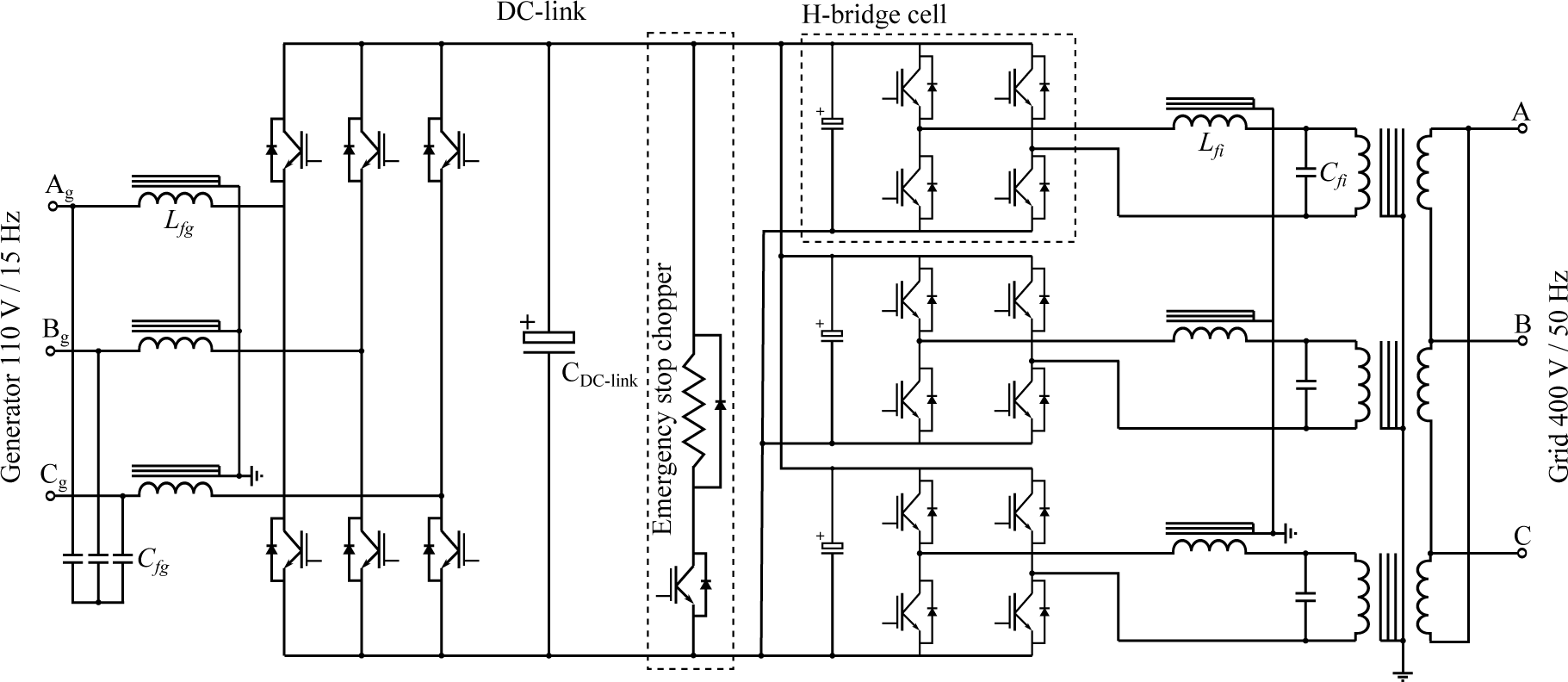
The electrical system for the grid connection of the marine current energy converter is presented in Figure 3. The generator-side converter is an IGBT based, two-level voltage source converter (2L-VSC) operating in rectifying mode when the system is injecting active power into the grid and in inverting mode during the turbine start-up. The grid side converter is an IGBT based, three-level cascaded H-bridge voltage source converter (3L-CHBVSC) operating in inverting mode when power is injected into the grid and used as a active rectifier during the turbine start-up. A general structure for cascaded power converters is presented in [14] and a survey of different CHB topologies, control strategies and modulation schemes is presented in [15]. The use of multilevel converters brings several advantages such as smaller grid filters, higher efficiency and more sinusoidal voltages and currents among other advantages [16]. Cascaded operation from a single DC-link is achieved with the use of a Star/Delta transformer with the Star side connected to the inverter without a neutral connection as shown in Figure 3. This effectively isolates the H-bridges allowing them to operate from the same DC-link. A better utilization of the DC-link is also achieved as the inverter produces phase voltages from the DC-link instead of the usual line-to-line voltage [17,18].
There is a harmonics filter of the LC-topology after each converter as shown in Figure 3. The filters are intended to remove unwanted harmonics and reduce stress on the components as well as reduce the harmonic losses in the generator’s windings and core. The grid side LC-filter together with the transformer inductance form a LCL-filter. The LCL-filter has been shown to be an efficient and cost effective solution to meet grid demands. Design considerations and filter performance are discussed in [19,20].
A emergency stop chopper is placed on the DC-link to stop the turbine in case of DC-link overvoltage due to grid faults, grid loss and other faults. As stated earlier the power flow is bidirectional for both converters. During start-up active power is drawn from the grid to the DC-link and the grid-side inverter operates as an active rectifier. During start-up the current to the machine is limited to 25% of the rated current to limit the rate of acceleration and reduce stress on the turbine.
4. Control System
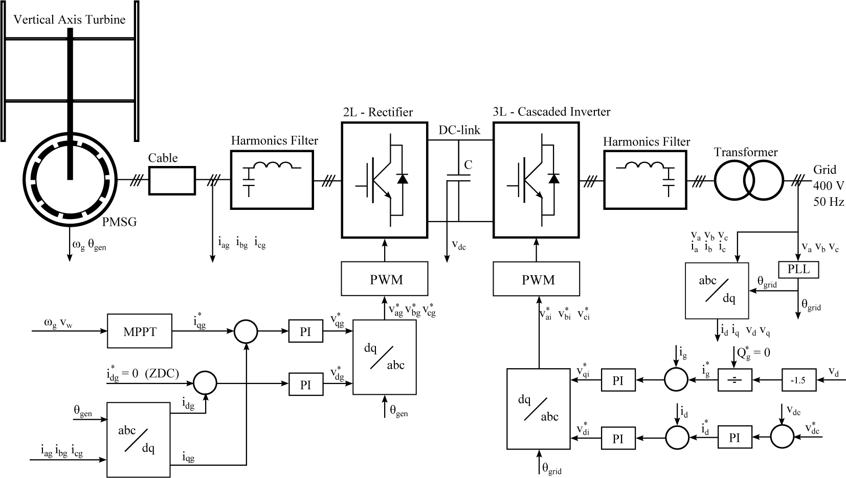
When designing the system for grid connection there are three main aspects that need to be take into consideration. The first is the ability to keep the maximum power absorption from the turbine as a function of the water velocity. The second is the ability to control the DC-link voltage of the power converters. Last is controlling the reactive power injected into the grid, as this is a relatively small unit the reactive power injected into the grid will be set to Q* = 0. In this set-up the grid side converter will be used to control the reactive power injected into the grid and the DC-link voltage of the converters. The generator-side converter will be used to control the active power from the marine current energy converter and to keep the units absorbed power at a maximum. The block digram of the proposed system is shown in Figure 4.
4.1. Generator-Side Control
The maximum power point (MPPT) block shown in Figure 4 is a MPPT with optimal TSR. The maximum power operation of the turbine is achieved by keeping the marine current turbine at it’s optimal TSR, λT,opt. This control algorithm uses the measured water velocity, vw, to produce an optimal rotational speed, ωopt, for the machine in accordance with the optimal TSR. The speed is then controlled by the rectifier and kept at optimum during steady state.
Different aspects of PMSG control for variable-speed operation are discussed in [21]. Here a zero d-axis current control (ZDC), idg = 0, is used and gives a linear relationship between the stator current is and the electromagnetic torque Te assuming a constant rotor flux linkage, λr, the expression is given in Equation 3. Where p is the number of generator pole pairs. The rotor flux angle, θgen, is measured with sensors in the air-gap of the generator. The three-phase stator currents iag, ibg and icg are measured and transformed into the dq-axis currents, idg, iqg. As seen in the Figure 4 the two currents are then compared with their reference currents, , , and the error is sent to a PI controller respectively. The PI controllers then generate the reference dq-voltages, , , used for the rectifier control. The dq-voltages are then converted back to a stationary frame, , and , and the three-phase sinusoidal voltages are sent into a pulse width modulation (PWM) generation block. A carrier-based sinusoidal pulse width modulation (SPWM) scheme is employed to generate the gate pulses for the rectifier.
4.2. Grid-Side Control
The grid voltages, va, vb and vc, are measured and fed into the PLL block used to track the grid voltage vector and generate the grid voltage angle θgrid used for the voltage oriented control (VOC) of the grid-side inverter. The VOC is based on the transformation from the stationary abc reference frame to the synchronous dq frame. All the control is then placed in the synchronous frame, where all the control variables are DC components. As shown in Figure 4 the grid angle, θgrid, is used to go from the stationary reference frame for both the voltages, va, vb, vc, and the currents ia, ib, ic, to the synchronous reference frame vd, vq and id,iq, respectively. There are three PI controllers that control the inverter: two PI controllers are used for the control of the the currents id and iq and one outer PI controller is used to control the DC-link voltage, vdc. To apply the VOC the d-axis of the synchronous frame is aligned with the grid voltage vector. The d-axis grid voltage is set to be equal to the grid voltage vector in magnitude, vd = vgrid and the q-axis voltage is equal to zero, vq = 0. From this the active and reactive power injected into the grid can be calculated as follows in Equation 4.
The q-axis current reference can then be obtained from Equation 5. In our case we have set the reference for the reactive power, Q*, to zero to achieve unity power factor operation in steady state.
The reference for the active power, represented by the d-axis current reference , is generated by the PI controller used to keep the DC-link voltage at a fixed level. When the inverter injects active power into the grid the DC-link voltage is kept steady by the controller to a reference value of .
As seen in the Figure 4 the two currents, id and iq are then compared with their reference currents, , , and the error is sent to a PI controller respectively. The PI controllers then generate the reference dq-voltages, , , used for the control of the three-level inverter. The synchronous frame voltage references, and , are converted back to a stationary frame, , and , and the three-phase sinusoidal voltages are sent into a PWM generation block as shown in Figure 4. A carrier-based SPWM scheme is used to generate the gate pulses for the inverter.
4.3. Simulations of the Proposed System
The system as described in this section and section III was implemented in Matlab/SIMULINK using the power systems library. The operational scheme for the marine current energy converter is shown in Table 2 together with parameters used in the simulation.
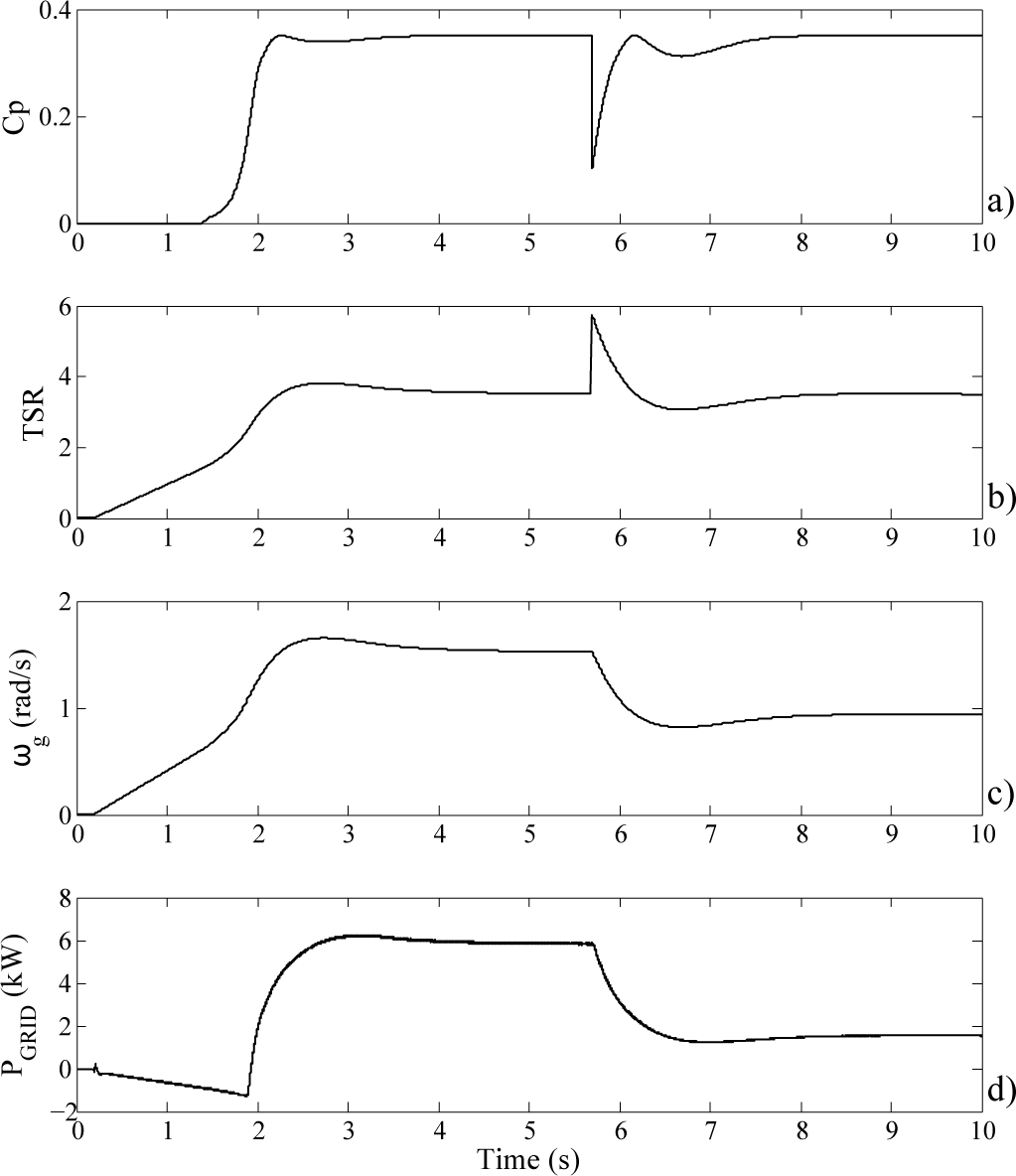
All PI controllers are implemented with anti-windup schemes. The curve presented in Figure 2 is loaded as a look-up table (LUT) for the simulation with values outside of the range of the curve rapidly dropping to Cp = 0. The LUT combined with Equation 2 and a fixed rated water velocity, vw, of 1.3 m/s produce the mechanical power absorbed by the turbine. At the simulation time t = 0.2 s the start-up of the turbine is initiated. The turbine is operated until a steady state is reached. Then a step in water velocity is introduced at t = 5.7 s. The water velocity drops from 1.3 m/s to 0.8 m/s corresponding to a 77% power drop at optimal Cp (1[pu] to 0.23[pu]). Since the TSR is a function of the water velocity the step will be reflected in the turbine Cp. The simulation is executed until a new steady state is reached.
5. Results and Discussion
The results from the simulation of the proposed system are presented below. In Figure 5 the turbine Cp, TSR, generator rotational speed and grid power flow, for the full simulation time, are presented. The Cp, Figure 5a, is zero until the turbine reaches a sufficient rotational speed to start absorbing power from the water flow. The controller keeps the turbine at optimal TSR, Figure 5b, during steady state ensuring optimal power absorption. As the turbine rotational speed increases during start-up, Figure 5c, there is some overshoot before the turbine reaches the nominal rotational speed. The magnitude of the overshoot can be tuned in by adjusting the controller but might result in unnecessarily slow reactions to smaller flow variations. An introduction of a feed-forward term to the MPPT controller, where an estimation of the turbine torque is introduced can potentially reduce the overshoot without reducing the speed of the controller. Power is drawn from the grid for roughly 2 s during the start-up of the turbine, Figure 5d, at which point the power flow direction shifts and power is injected into the grid.
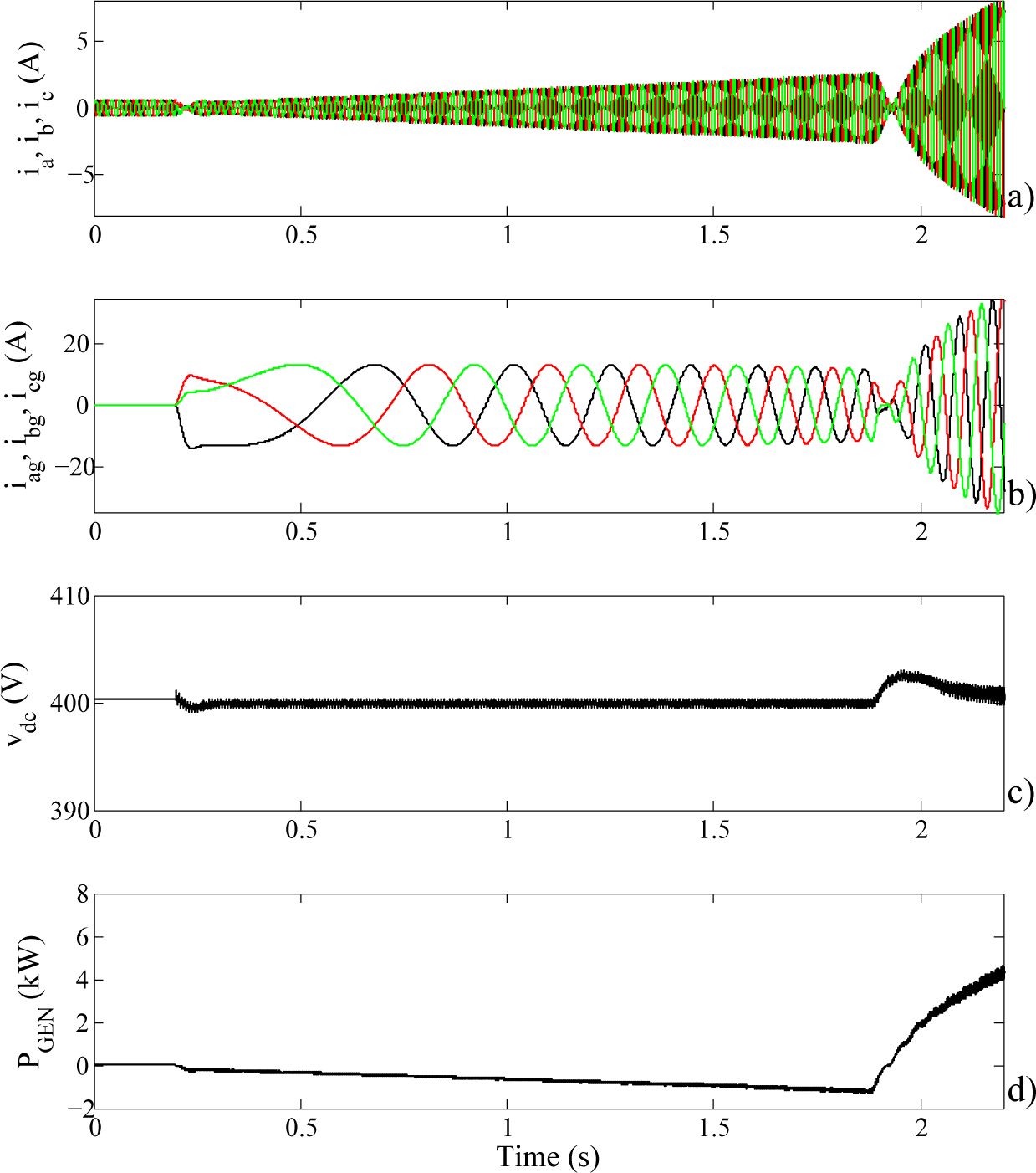
The grid-side and generator-side currents, DC-link voltage and generator power flow during start-up are presented in Figure 6. The current drawn from the grid slowly increases as the turbine is accelerated, Figure 6a. The current limitation set on the generator-side converter, Figure 6b, is operating as expected limiting the current to 25% of the rated current. The grid-side current increases to be able to keep the fixed current on the generator-side as the machine gains rotational speed. A small drop in DC-link voltage can be observed, Figure 6c, as the system is started at t = 0.2 s. The DC-link voltage has a small overshoot as the power flow in the system shifts, at roughly t = 1.9 s, to injecting active power into the grid. Figure 6d shows the generator power flow, where the power flow goes positive at roughly 2 s and power is extracted from the flowing water.
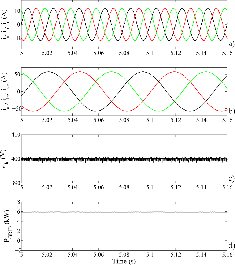
Figure 7 shows the system in steady state operation during rated conditions. The grid-side and generator-side currents are presented in Figure 7a and Figure 7b, respectively. There is very little ripple in both sets of currents. The DC-link voltage, Figure 7c, is kept steady at the reference level of 400 V with some ripple. Figure 7d displays the active power injected into the grid.
The dynamic performance of the system during a step in water velocity is presented in Figure 8. The step in water velocity is shown in Figure 8a. The systems ability to keep the reactive power injected into the grid at the set reference level, Q* = 0, is displayed in Figure 8b. Where a small change in the reactive power can be seen as the step is made. The DC-link voltage is kept steady at the set reference level, vdc* = 400 V, by the grid side converter as expected with a small dip in voltage short after the step, Figure 8c. The generator-side rectifier reduces the generator output power in order to reach a new steady state, Figure 8d, corresponding to optimal power extraction for the new water velocity.
6. Conclusions
A system for grid connection of the 7.5 kW marine current energy converter located in Söderfors, Sweden, is proposed. The generator-side converter is an IGBT based, two-level VSC and the grid-side converter is an IGBT based, three-level cascaded H-bridge VSC. Bidirectional power flow enabled by the selected topology enables start-up of the none self-starting, fixed pitch, vertical axis turbine and eliminates the need for an additional system for this task. The results show that the start-up of the turbine is executed successfully with some overshoot in the rotational speed before a steady state is reached. Operation during steady state at rated conditions is presented. The system shows good dynamic behaviour during a step in water velocity where a new steady state is quickly reached.
Acknowledgments
This work was conducted within the STandUp for ENERGY strategic research framework. The Swedish Energy Agency and Vattenfall are acknowledged for supporting the Swedish Centre for Renewable Electric Energy Conversion.
Author Contributions
The main author, Senad Apelfröjd, did the majority of the work in this paper in collaboration with Rickard Ekström. The work was supervised by Karin Thomas and Mats Leijon. All authors contributed to the editing and reviewing of the paper.
Conflicts of Interest
The authors declare no conflict of interest.
References
- Ben Elghali, S.; Balme, R.; Le Saux, K.; Benbouzid, M.; Charpentier, J.; Hauville, F. A simulation model for the evaluation of the electrical power potential harnessed by a marine current turbine. IEEE J. Ocean. Eng. 2007, 32, 786–797. [Google Scholar]
- Zhou, Z.; Scuiller, F.; Charpentier, J.F.; Benbouzid, M.; Tang, T. An up-to-date review of large marine tidal current turbine technologies, Proceedings of the Power Electronics and Application Conference, Shanghai, China, 5–8 November 2014.
- Bahaj, A.S. Generating electricity from the oceans. Renew. Sustain. Energy Rev. 2011, 15, 3399–3416. [Google Scholar]
- Ben Elghali, S.; Benbouzid, M.; Charpentier, J.F. Marine tidal current electric power generation technology: State of the art and current status, Proceedings of the Electric Machines & Drives Conference on 2007. IEMDC’07, IEEE International, Antalya, Turkey, 3–5 May 2007; 2, pp. 1407–1412.
- Yuen, K.; Thomas, K.; Grabbe, M.; Deglaire, P.; Bouquerel, M.; Osterberg, D.; Leijon, M. Matching a permanent magnet synchronous generator to a fixed pitch vertical axis turbine for marine current energy conversion. IEEE J. Ocean. Eng. 2009, 34, 24–31. [Google Scholar]
- Lalander, E.; Leijon, M. Numerical modeling of a river site for in-stream energy converters, Proceedings of the 8th European Wave and Tidal Energy Conference, EWTEC09, Uppsala, Sweden, 7–10 September 2009; pp. 826–832.
- Yuen, K.; Lundin, S.; Grabbe, M.; Lalander, E.; Goude, A.; Leijon, M. The Söderfors project: Construction of an experimental hydrokinetic power station, Proceedings of the 9th European Wave and Tidal Energy Conference (EWTEC’11), Southampton, UK, 5–9 September 2011; pp. 1–5.
- Lundin, S.; Forslund, J.; Carpman, N.; Grabbe, M.; Yuen, K.; Apelfröjd, S.; Goude, A.; Leijon, M. The Söderfors project: Experimental hydrokinetic power station deployment and first results, Proceedings of the 10th European Wave and Tidal Conference (EWTEC13), Aalborg, Denmark, 2–5 September 2013.
- Grabbe, M.; Yuen, K.; Apelfröjd, S.; Leijon, M. Efficiency of a directly driven generator for hydrokinetic energy conversion. Adv. Mech. Eng. [CrossRef]
- Yuen, K.; Apelfröjd, S.; Leijon, M. Implementation of control system for hydrokinetic energy converter. J. Control Sci. Eng. [CrossRef]
- Grabbe, M.; Yuen, K.; Goude, A.; Lalander, E.; Leijon, M. Design of an experimental setup for hydro-kinetic energy conversion. Int. J. Hydropower Dams 2009, 15, 112–116. [Google Scholar]
- Kjellin, J.; Bernhoff, H. Electrical starter system for an H-Rotor Type VAWT with PM-generator and auxiliary winding. Wind Eng 2011, 35, 85–92. [Google Scholar]
- Thomas, K.; Grabbe, M.; Yuen, K.; Leijon, M. A low-speed generator for energy conversion from marine currents-experimental validation of simulations. Proc. Inst. Mech. Eng. Part A 2008, 222, 381–388. [Google Scholar]
- Corzine, K.; Familiant, Y. A new cascaded multilevel H-bridge drive. Power Electron 2002, 17, 125–131. [Google Scholar]
- Malinowski, M.; Gopakumar, K.; Rodriguez, J.; Perez, M.A. A survey on cascaded multilevel inverters. IEEE Trans. Ind. Electron. 2010, 57, 2197–2206. [Google Scholar]
- Kouro, S.; Malinowski, M.; Gopakumar, K.; Pou, J.; Franquelo, L.G.; Wu, B.; Rodriguez, J.; Pérez, M.A.; Leon, J.I. Recent advances and industrial applications of multilevel converters. IEEE Trans. Ind. Electron. 2010, 57, 2553–2580. [Google Scholar]
- Casadei, D.; Grandi, G.; Lega, A.; Rossi, C. Multilevel operation and input power balancing for a dual two-level inverter with insulated DC sources. IEEE Trans. Ind. Appl. 2008, 44, 1815–1824. [Google Scholar]
- Grandi, G.; Rossi, C.; Ostojic, D.; Casadei, D. A new multilevel conversion structure for grid-connected PV applications. IEEE Trans. Ind. Electron. 2009, 56, 4416–4426. [Google Scholar]
- Ahmed, K.; Finney, S.; Williams, B. Passive filter design for three-phase inverter interfacing in distributed generation, Proceedings of the Compatibility in Power Electronics, 29 May–7 June 2007; pp. 1–9.
- Liserre, M.; Blaabjerg, F.; Hansen, S. Design and control of an LCL-filter-based three-phase active rectifier. IEEE Trans. Ind. Appl. 2005, 41, 1281–1291. [Google Scholar]
- Chinchilla, M.; Arnaltes, S.; Burgos, J. Control of permanent-magnet generators applied to variable-speed wind-energy systems connected to the grid. IEEE Trans. Energy Convers 2006, 21, 130–135. [Google Scholar]


| Generator parameters | Values |
|---|---|
| Number of poles | 112 |
| Rotational speed | 1.57 rad/s |
| Line-to-Line Voltage | 110 VLLrms |
| Frequency | 15 Hz |
| Power | 7.5 kW |
| Mechanical Torque | 5.93 kNm |
| Mechanical Inertia | 2445 kgm2 |
| Stator Winding Resistance | 0.335 Ω |
| Stator dq-axis Inductance | 3.5 mH |
| Main Blocks | Parameters | Values |
|---|---|---|
| Nonsalient PMSG | 7.5 kW, 110 V | Parameters in Table 1 |
| Land cable | Length | 150 m |
| Resistance | 0.524 Ω/km | |
| Inductance | 0.24 mH/km | |
| Capacitance | 0.45 μF/km | |
| Rectifier | Converter type | 2L-VSC |
| Modulation scheme | SPWM | |
| Switching frequency | 4 kHz | |
| Harmonic filter | LC (1.6 mH, 10 μF) | |
| DC-link filter | Capacitor Bank | 16.5 mF |
| Inverter | Converter type | 3L-CHBVSC |
| Modulation scheme | SPWM | |
| Switching frequency | 6 kHz | |
| Harmonic filter | LC (3.1 mH, 10 μF) | |
| Transformer | Star/Delta | 340 V/400 V |
| Power rating | 7.5 kVA | |
| Primary resistance | 180 mΩ | |
| Secondary resistance | 230 mΩ | |
| Primary leak. inductance | 0.52 mH | |
| Secondary leak. inductance | 0.37 mH | |
| Grid | Three-phase symmetrical | 400 V/50 Hz |
| Line inductance | 0.5 mH | |
| Line Resistance | 34 mΩ | |
| Control Scheme | For generator | ZDC scheme |
| For turbine | Optimal TSR | |
| Operational Parameters | Rotational speed set-point | from MPPT |
| DC-link voltage set-point | = 400 V |
© 2015 by the authors; licensee MDPI, Basel, Switzerland This article is an open access article distributed under the terms and conditions of the Creative Commons Attribution license (http://creativecommons.org/licenses/by/4.0/).
Share and Cite
Apelfröjd, S.; Ekström, R.; Thomas, K.; Leijon, M. A Back-to-Back 2L-3L Grid Integration of a Marine Current Energy Converter. Energies 2015, 8, 808-820. https://doi.org/10.3390/en8020808
Apelfröjd S, Ekström R, Thomas K, Leijon M. A Back-to-Back 2L-3L Grid Integration of a Marine Current Energy Converter. Energies. 2015; 8(2):808-820. https://doi.org/10.3390/en8020808
Chicago/Turabian StyleApelfröjd, Senad, Rickard Ekström, Karin Thomas, and Mats Leijon. 2015. "A Back-to-Back 2L-3L Grid Integration of a Marine Current Energy Converter" Energies 8, no. 2: 808-820. https://doi.org/10.3390/en8020808