Article

Different Control Techniques of Permanent Magnet Synchronous Motor with Fuzzy Logic for Electric Vehicles: Analysis, Modelling, and Comparison

1
Laboratoire de Technologie Industrielle et de l’Information, Faculté de Technologie, Université de Bejaia, Bejaia 06000, Algeria
2
Université de Lorraine, GREEN, F-54000 Nancy, France
*
Author to whom correspondence should be addressed.
Energies 2023, 16(7), 3116; https://doi.org/10.3390/en16073116
Submission received: 26 February 2023 / Revised: 22 March 2023 / Accepted: 27 March 2023 / Published: 29 March 2023
(This article belongs to the Special Issue Vehicle Dynamics and Control)

Abstract

:
This paper presents a detailed analysis and comparative study of three torque control methodologies with fuzzy logic, namely direct torque control (DTC), fuzzy direct torque control (FDTC), and model predictive direct torque control (MPDTC), for PMSM control applied to an electric vehicle. The three control strategies are designed and developed to control torque in order to achieve vehicle requirements, such as minimum torque and flux ripples, fast dynamic response, and maximum efficiency. To enhance the performance and efficiency of the overall drive, a bidirectional DC/DC buck-boost converter is connected to the Li-ion battery. In addition, a fuzzy logic controller (FLC) is used in the outer loop to control the speed of the PMSM. As a result, the tuning difficulty of the conventional proportional-integral (PI) controller is avoided and the dynamic speed response is improved. Simulation results obtained from the three control techniques establish that the proposed system via the MPDTC technique reduces the torque ripples, flux ripples, reduces the THD of the PMSM current, and achieves a faster transient response. Additionally, the MPTDC technique enabled the electric vehicle to cover the longest distance, with approximately 110.72 km in a charging cycle. The real-time simulation is developed using the RT LAB simulator, and the obtained results confirm the superiority of the MPDTC technique over conventional DTC and FDTC techniques.

1. Introduction

The transportation and automotive industries face a major challenge in reducing environmental impacts, particularly in terms of CO2 emissions, sulfur oxides, and nitrogen oxides. Policies aim to reach carbon neutrality in this sector by 2050 as part of the ecological and energy transition [1]. Fuel cell electric vehicles (FCEVs), battery electric vehicles (BEVs), and hybrid electric vehicles (HEVs) are considered key solutions to current environmental problems. BEVs are purely electric vehicles powered solely by batteries; they offer many advantages, such as zero emissions, optimal performances, independence from oil, and a quiet and smooth operation with little environmental noise [2,3]. The automotive industry and the scientific community attach great importance to the development of electric vehicles (EVs), focusing on key aspects of their performances. Ongoing research aims to improve the energy source of EVs, their structure, and their electrical drive system, which is a major area of interest for automotive manufacturers and researchers. The propulsion system of an EV consists mainly of an electric motor, a controller, a battery stack, and power converters. To ensure the propulsion of EVs, there are several types of electric motors, such as direct current (DC) motors, induction motors (IM), variable reluctance motors (VRM), and permanent magnet synchronous motors (PMSM) [4,5].
The PMSM has gained significant attention for its potential in high-performance automotive applications. Its exceptional characteristics, including high power density, excellent efficiency, and remarkable torque density, make it a promising choice [6,7]. Today, there are many control strategies for PMSM drives, including field-oriented control (FOC) [8], direct flux control (DFC) [9], and direct torque control (DTC) [10]. Compared to the FOC and the DFC, the DTC offers better torque response and is considered a more appropriate control algorithm for PMSM. However, classical DTC has problems, such as significant torque, flux, and current ripples, a variable switching frequency, and other low-speed problems [11]. Many methods have been proposed to mitigate these drawbacks. The authors of [12,13] proposed a DTC-SVM scheme based on a constant switching frequency. In [14], the authors used multilevel inverters to improve the DTC. However, high switching losses appeared. The authors of [15,16] optimized the PI regulator parameters using the genetic algorithm (GA), and the particle swarm optimization (PSO), resulting in an improvement in the transient response. However, there is not much reduction in torque and flux ripple in steady state. In recent years, there has been a growing emphasis on integrating artificial intelligence (AI) techniques, such as neural networks and fuzzy logic, into DTC to enhance its performance. To improve the DTC technique, the researchers of [17] proposed replacing the torque and flux hysteresis regulators with fuzzy logic controllers. In [18], the authors proposed the use of a switching controller based on artificial neural network, while in [19], the authors proposed a fuzzy logic switching controller, and the results showed good performance in steady state. Predictive model control (MPC) combined with DTC has attracted the attention of researchers due to its high performance and simplicity of implementation [20,21,22]. MPC relies on a mathematical model to predict the behavior of a system and then minimizes a pre-determined cost function to achieve the desired control goals. In [7,23,24,25], a new MPDTC scheme is proposed to minimize torque and flux ripples, as well as the PMSM current THD. In [26], an improved MPDTC method is proposed to increase torque by enhancing the magnetic field with constant load angle, and the experimental results show that the torque capacity of the proposed method has been improved and the extreme output torque is stable. In [27,28], the authors further reduced torque and flux ripple by proposing a predictive control technique by pulse width modulation (MPTC-PWM). The authors of [29,30] proposed discrete space vector modulation (DSVM) to achieve flux-linkage and electromagnetic torque ripple reduction in finite-set model predictive torque control (FS-MPTC). In [31], the authors proposed an MPTC based on a discrete-time state-space model, and the experimental results showed good performance, including a reduction in torque ripple, minimal current THD, and fast dynamic response of torque.
There are many control techniques for electric machines that offer various possibilities for optimal control. However, it is still uncertain which technique provides the best results due to the differences in electric machines and their parameters. Most studies only compare basic DTC with a modified DTC, or they compare different modified DTC schemes. However, few studies have compared different improved DTC techniques, and none have included FDTC and MPDTC methods. Additionally, these studies have not considered the impact on battery performance.
In this work, three control strategies, namely DTC, FDTC, and MPDTC, are analyzed and compared. The three control strategies are designed and developed to control the torque in order to meet the requirements of the vehicle. The results obtained using Matlab/Simulink and those obtained using a RT LAB simulator clearly showed that the system proposed using the MPDTC technique reduces torque and flux ripples, as well as the current THD of PMSM, and results in a faster transient response.
To achieve the mentioned objectives, this document is organized into six sections: Section 1 is an introduction that provides a general idea of the studied field. In Section 2, the detailed description and modeling of the studied system is given. In Section 3, the DTC, FDTC, and MPDTC control strategies are explicitly detailed. The simulation results obtained are presented in Section 4. Section 5 presents the results obtained by the real-time RT Lab simulator. Finally, a main conclusion summarizes and proves the proposed strategies.

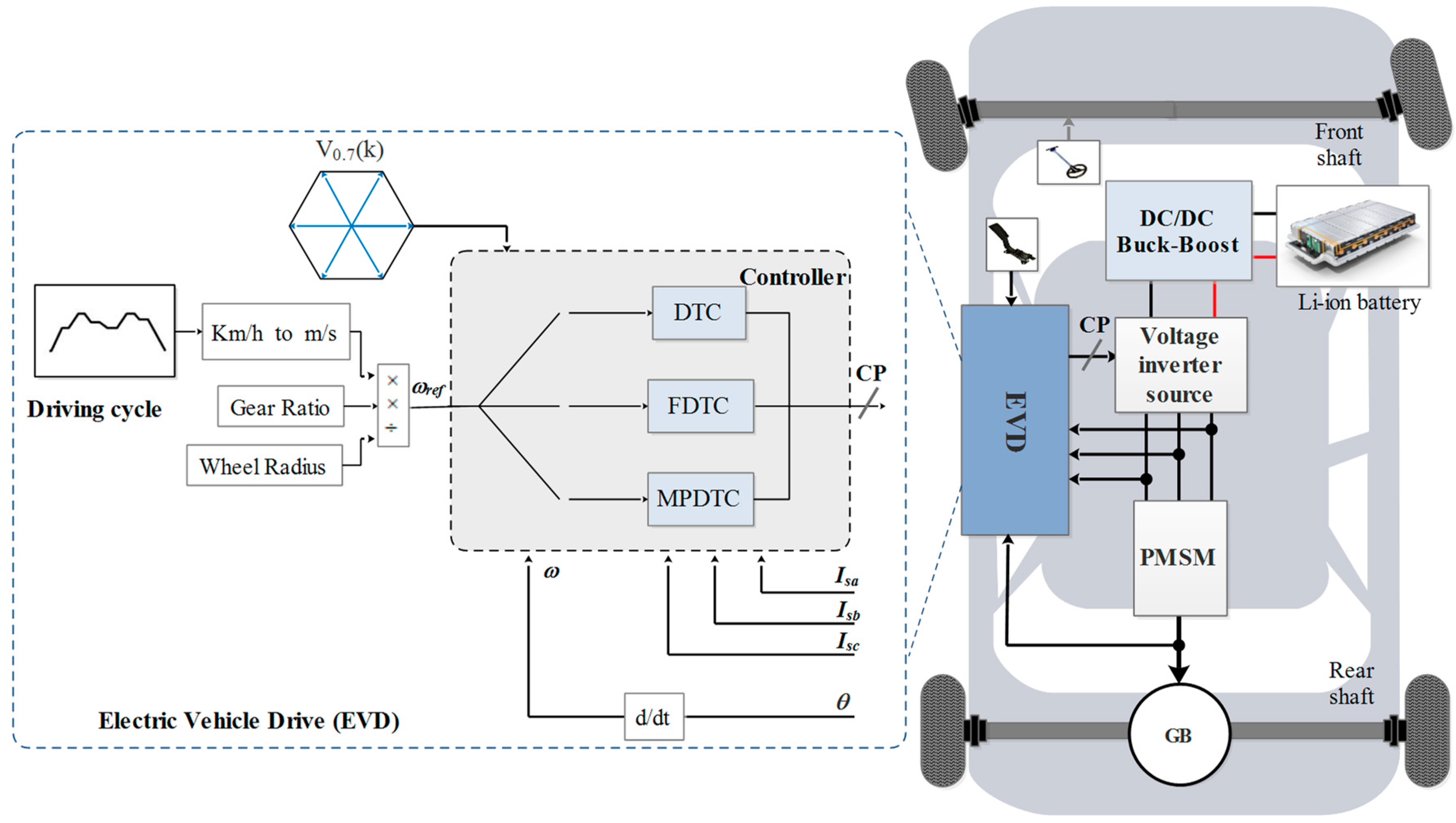
2. System Configuration and Modeling

Figure 1 shows the general configuration of an electric vehicle, which includes a Li-ion battery power supply unit, a DC/DC buck-boost converter, a DC/AC converter, a PMSM with its final gearbox, the electric vehicle drive (EVD), and various sensors and transducers. The Li-ion battery provides power to the vehicle through a bi-directional buck-boost converter, while the control pulses (CP) generated by the EVD’s torque control techniques are applied to the voltage source inverter (VSI) to operate the PMSM.

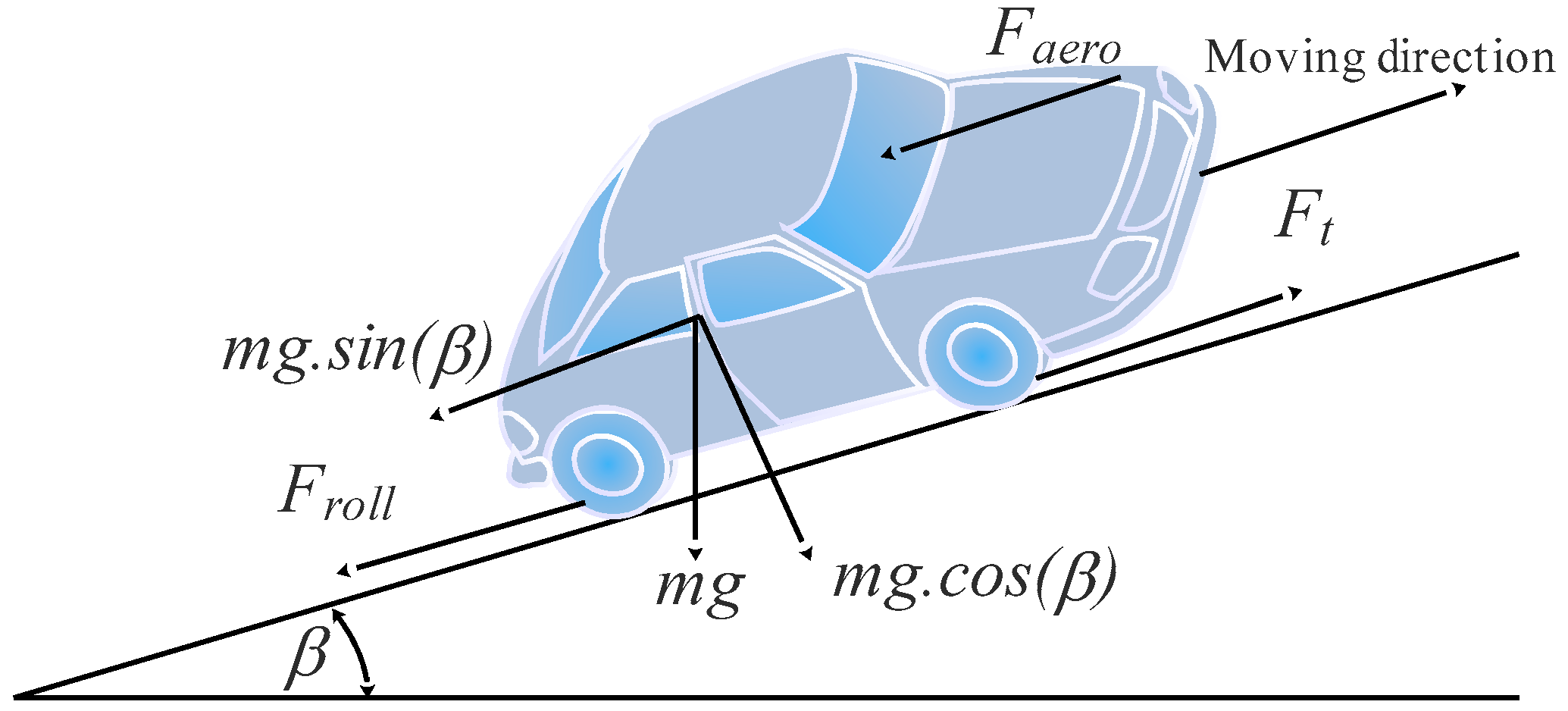
2.1. Mathematical Model of the Electric Vehicle

When an electric vehicle is driving on a slope (β) at a certain velocity (v), it is subjected to multiple forces, such as rolling resistance force (Froll), aerodynamic drag force (Faero), slope force (Fslope), and acceleration force (Facc), as depicted in Figure 2. The total traction force (Ft) that is necessary to drive the vehicle can be expressed as follows [32,33]:
F t = F r o l l + F a e r o + F s l o p e + F a c c

2.1.1. Rolling Resistance Force

This force is mainly due to the friction of the vehicle’s tires on the road. It acts in the opposite direction of the movement of the vehicle. The mathematical expression for the rolling resistance force is:
F r o l l = m g f r o cos ( β )
where m , g and fro are the vehicle total mass, the gravity acceleration and the coefficients of rolling resistance, respectively.

2.1.2. Aerodynamic Drag

Aerodynamic drag force is caused by the friction of the air overall body of the vehicle while moving. The magnitude of this force depends on the direction of the wind, the frontal area of the vehicle, and its shape. Its expression is given by:
F a e r o = 1 2 ρ a i r A f C d ( v + v w ) 2
where ρ a i r , A f and C d are the air density, the vehicle frontal surface and the penetration air coefficient, respectively.

2.1.3. Slope Force

The slope force refers to the gravitational force acting on a vehicle as it moves along an inclined surface. This force is dependent on the slope angle (β) of the road and is directly proportional to the mass (m) of the vehicle. This force is expressed as follows:
F s l o p e = m g sin ( β )

2.1.4. Acceleration Force

This force represents the dynamic term for the vehicle’s acceleration or deceleration, and it can be expressed as follows:
F a c c = k m m d V e d t = k m m γ
where km is the rotational inertia coefficient, γ is the vehicle acceleration.
The total tractive force (Ft) is the sum of all these forces and can be given by:
F t = F t i r e + F a e r o + F s l o p e + F a c c = m g f r o cos ( β ) + 1 2 ρ a i r A f C d ( v + v w ) 2 + m g sin ( β ) + k m m γ
The total tractive torque is related to the tractive force by the relation:
T t = F t r
Finally, the torque produced by the traction motor can be calculated by:
T m = F t r η G G = r η G G [ m g f r o cos ( β ) + 1 2 ρ a i r A f C d ( v + v w ) 2 + m g sin ( β ) + k m m γ ]
where r, η G and G are the wheel radius, the transmission efficiency, and the reduction gear ratio, respectively.
The vehicle parameters are given in Table 1 [23].

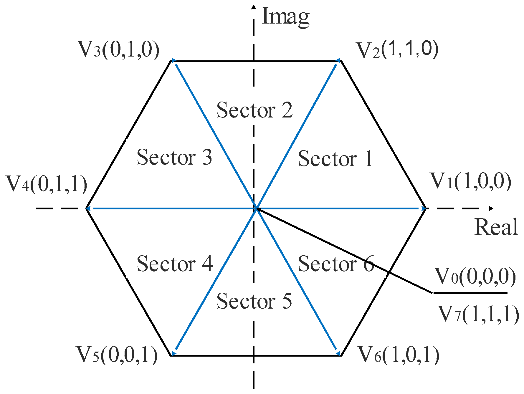
2.2. Voltage Source Inverter Model

In this work, a two-level voltage source inverter (2L-VSI) is considered to feed a PMSM. The DC bus voltage (Vdc) and the switching signals define the output phase voltages of VSI, as expressed in Equation (9) [34,35].
{ V a = S a V d c V b = S b V d c V c = S c V d c
Table 2 and Figure 3 display the switching states and their corresponding voltage vectors. There are eight possible switching states, with two being zero voltage vectors (V0, V7) and six being non-zero voltage vectors (V1, V2, V3, V4, V5, V6).

2.3. Permanent Magnet Synchronous Motor Model
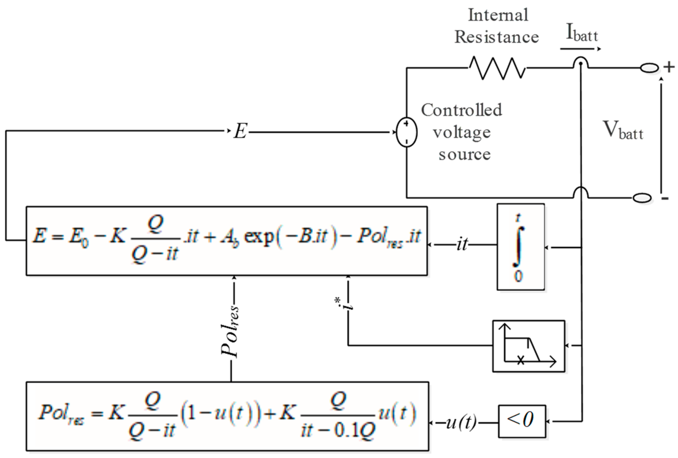
The electrical dynamic model of a PMSM in the d-q rotor reference frame are given by Equations (10) and (11) [17,36]:
V s d = R s I s d + d ϕ s d d t ω ϕ s q
V s q = R s I s q + d ϕ s q d t + ω ϕ s d
The totalized direct flux ϕ s d and quadrature flux ϕ s q can be determined using Equations (12) and (13):
ϕ s d = L s d I s d + ϕ f
ϕ s q = L s q I s q
The electromagnetic torque generated by the PMSM is given by Equation (14):
T e = 3 2 p I s q ( ( L s d L s d ) I s d + ϕ f )
Finally, the mechanical equation of the PMSM is given by:
J d Ω d t f Ω = T e T r
where J and f are the motor inertia and the viscous damping coefficient, respectively.
The PMSM parameters are summarized in Table 3 [23].

2.4. Battery Model

Li-ion batteries have a higher energy density, efficiency, and longer lifespan compared to other battery types such as Nickel-Metal Hydride, Nickel-Cadmium, lead-acid, or Nickel-Zinc [32]. In this study, we utilize the Li-ion battery model presented in Figure 4.
The voltage of the Li-ion battery during charging and discharging can be calculated using Equations (16) and (17) [23,37].
V d i s c h arg e = E 0 R · i K Q Q i t · ( i t + i ) + A exp ( B · i t )
V d i s c h arg e = E 0 R · i K Q i t 0.1 Q · i K Q Q i t · i t + A exp ( B · i t )
where E 0 , i t and i are the Li-ion battery constant voltage, the actual Li-ion battery charge and the filtered Li-ion battery current, respectively. R is the Li-ion battery internal resistance, K is the polarization constant Q is the Li-ion battery capacity, A is the exponential zone amplitude, and B is the exponential zone time constant inverse.
The state of charge of the Li-ion battery can be determined using Equation (18).
S O C b a t = 100 ( 1 1 Q 0 t i ( t ) d t )

3. Control Topologies

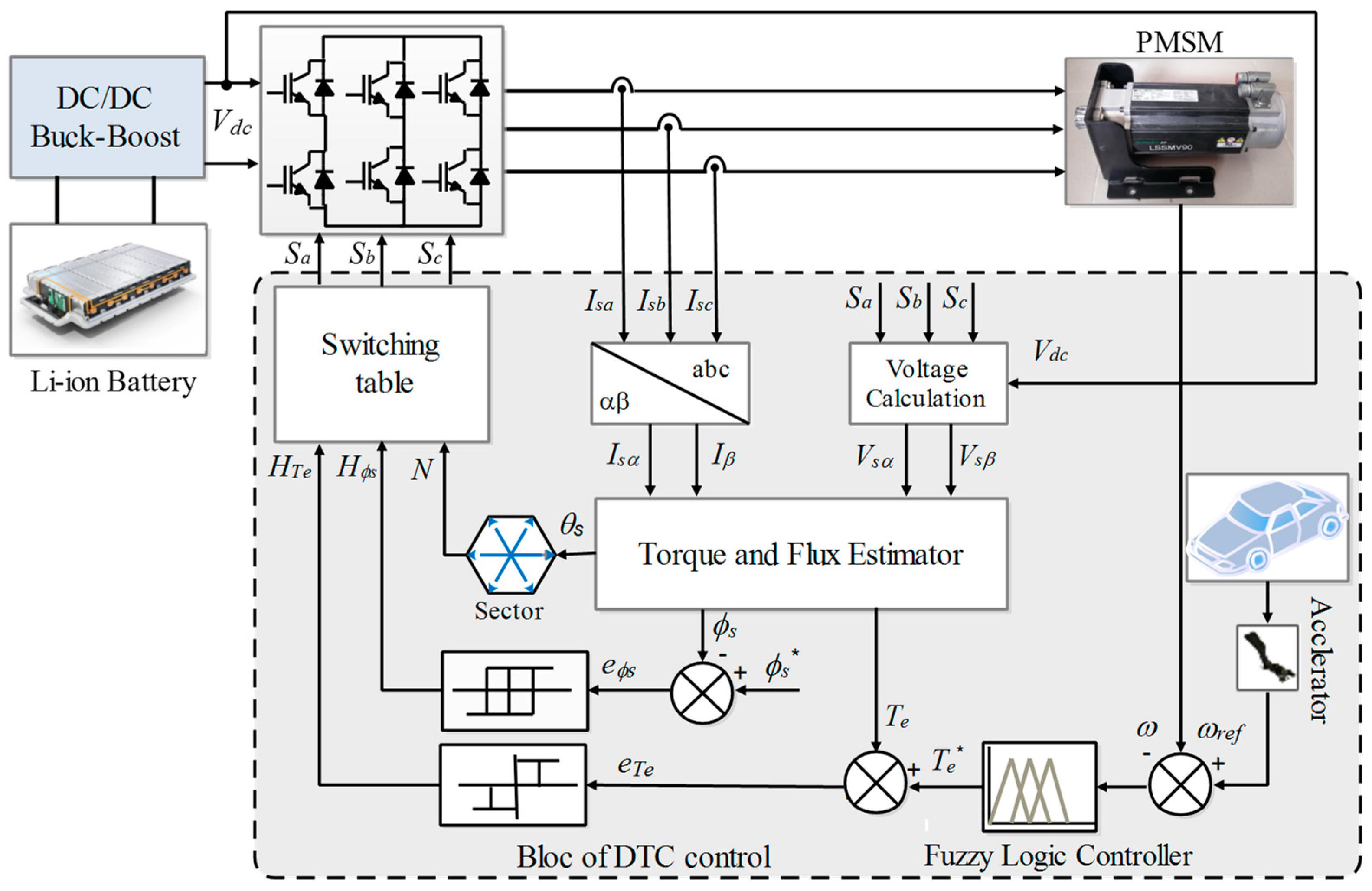
3.1. Direct Torque Control (DTC)

The DTC was originally proposed by Takahashi and Noguchi in the mid-1980s; since then, it has become a popular control strategy for traction applications due to its relative simplicity compared to other control methods [8,38]. Figure 5 illustrates the DTC scheme of a PMSM in an EV system. It comprises three-level (3L) and two-level (3L) hysteresis controllers, a torque and flux estimator, and a switching table. Based on the PMSM model, the torque and flux are estimated, and an optimal voltage vector is chosen based on the sector N where the stator flux is located, as well as the torque and stator flux demands obtained by 3L and 2L hysteresis comparators, respectively. The voltage vector selection is provided in Table 4, where Hϕs and HTe denote the output signals of the stator flux and electromagnetic torque hysteresis comparators, respectively, and Ni and Vi represent the ith sector and the voltage vector. After selecting the optimal voltage vector, it is applied to the 2L-VSI to minimize the flux and torque errors. The stator flux can be estimated as given in [11,39]:
ϕ s = 0 t ( V s ( t ) R s I s ( t ) ) d t
From Equation (19), the stator flux components are estimated by Equations (20) and (21):
ϕ s α = ϕ f + ( V s α R s I s α ) d t
ϕ s β = ( V s β R s I s β ) d t
The estimated amplitude of the stator flux and its phase angle are given by:
ϕ s = ( ϕ s α ) 2 + ( ϕ s β ) 2
θ s = tan 1 ( ϕ s β ϕ s α )
And the expression for the electromagnetic torque is:
T e = 3 2 p ( ϕ s α I s β + ϕ s β I s α )

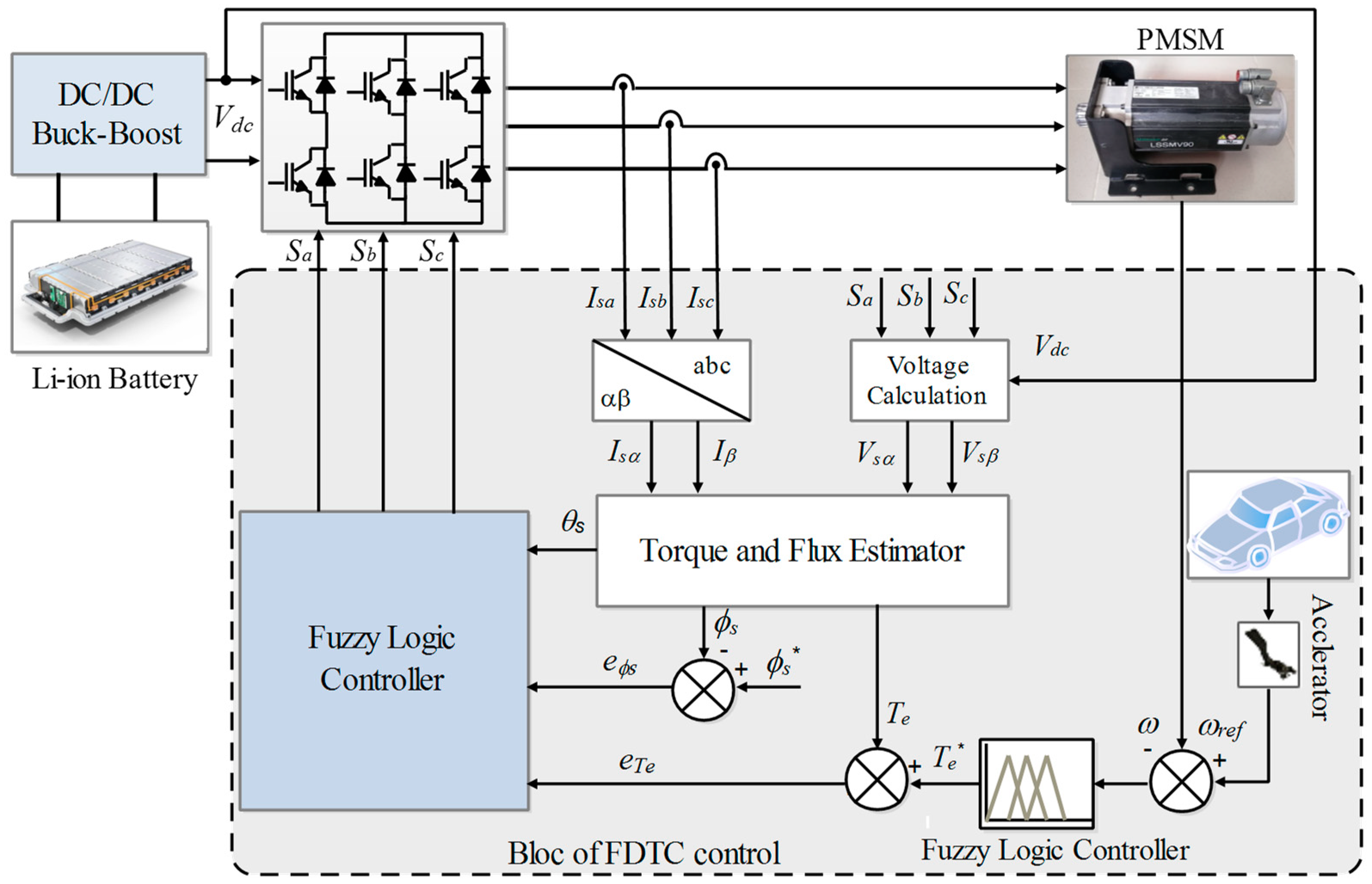
3.2. Fuzzy Direct Torque Control (FDTC)

Conventional DTC is a widely used method that offers excellent dynamic performance, including fast and accurate electromagnetic torque response. However, it suffers from certain limitations, such as high torque and stator flux ripples as well as high current THD, due to the use of switching tables and hysteresis controllers [40,41]. To address these limitations, a fuzzy technique has been proposed to improve the efficiency of conventional DTC control. This technique aims to replace hysteresis controllers and switching tables by a fuzzy logic controller (FLC). The FLC takes the torque error ( e T e ), the stator flux error ( e ϕ s ), and the stator flux angle ( θ s ) as input parameters and produces the states of the voltage source inverter switches as output parameters, as illustrated in Figure 6.

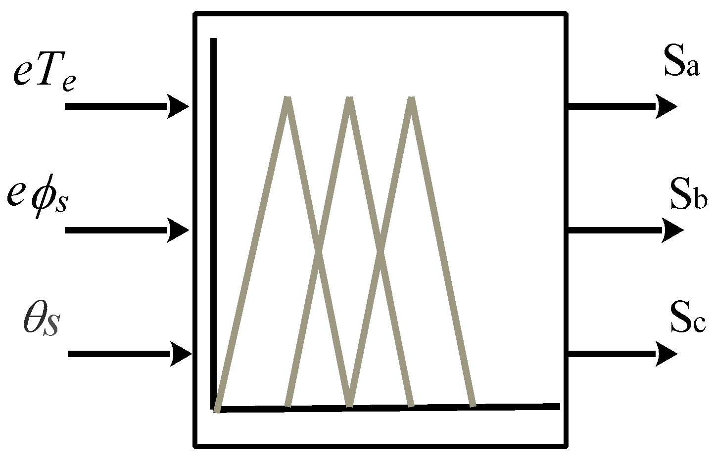
3.2.1. Fuzzification
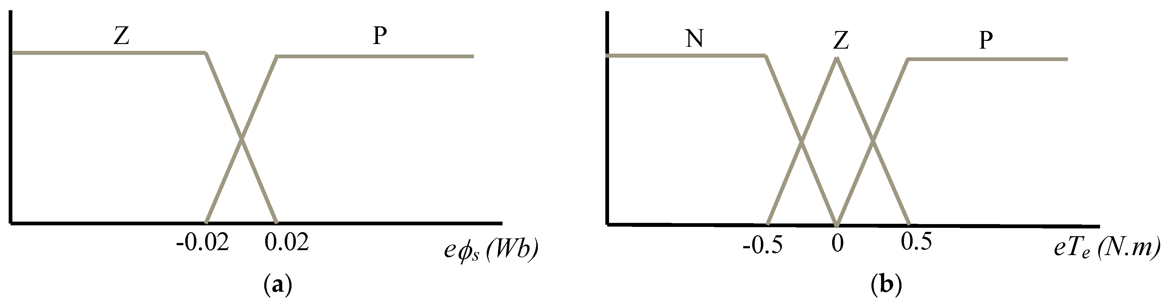
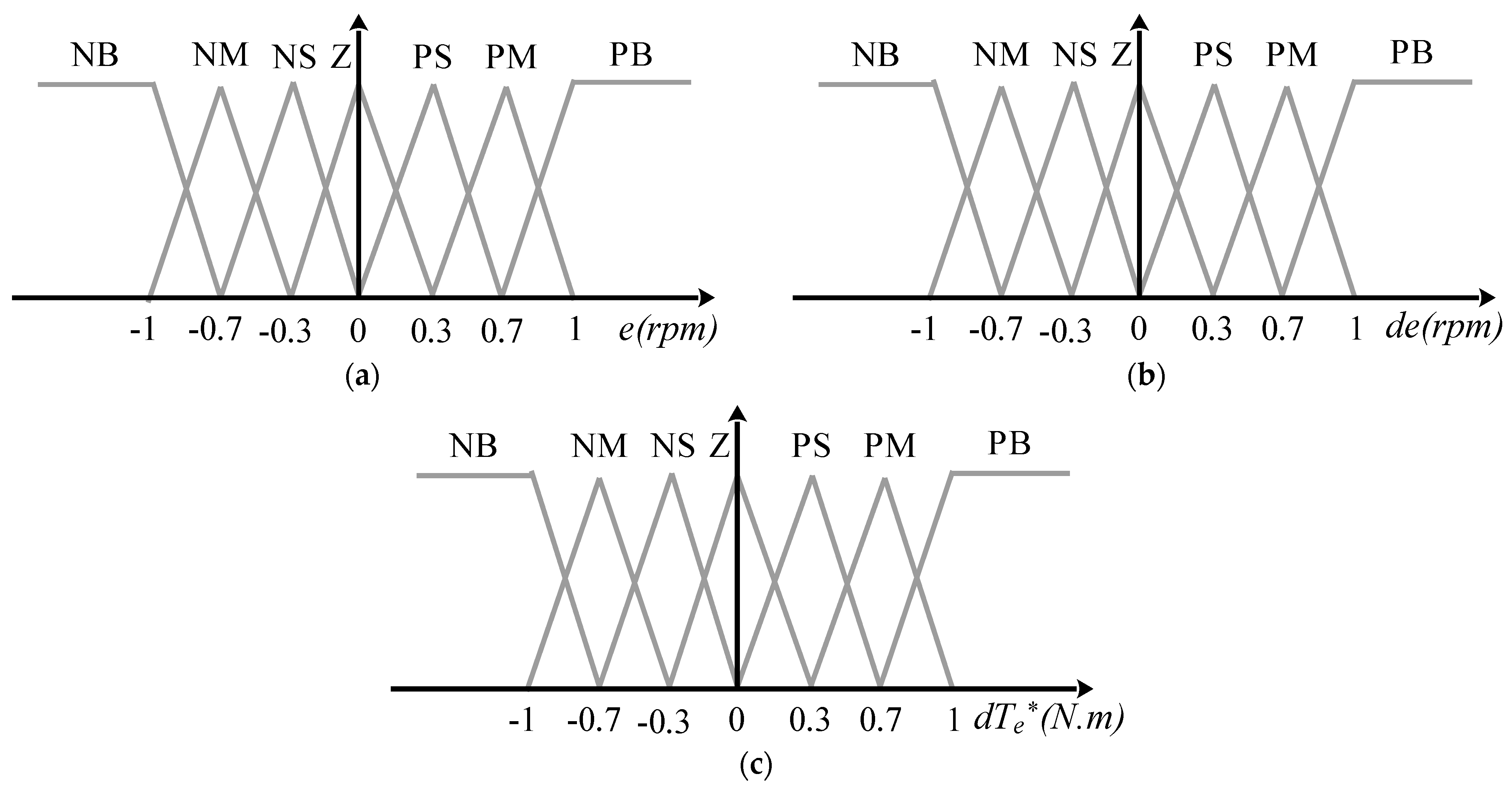
The first step in the fuzzification process is to convert the input variables into fuzzy variables using membership functions (MFs) and linguistic terms.
  • For torque error. The torque error ( e T e ) can be classified into three linguistic variables: “Negative” (N), “Zero” (Z) and “Positive” (P). These variables are inspired by the behavior of a three-level hysteresis comparator. As illustrated in Figure 7a, the variable Z is represented by a triangular MF, while L and H are represented by trapezoidal MFs.
  • For stator flux error. The stator flux error ( e ϕ s ) can be classified into two linguistic variables “Negative” (N) and “Positive” (P) inspired from the behavior of the two-level hysteresis comparator. As shown in Figure 7b, the L and H variables are represented by two trapezoidal MFs.
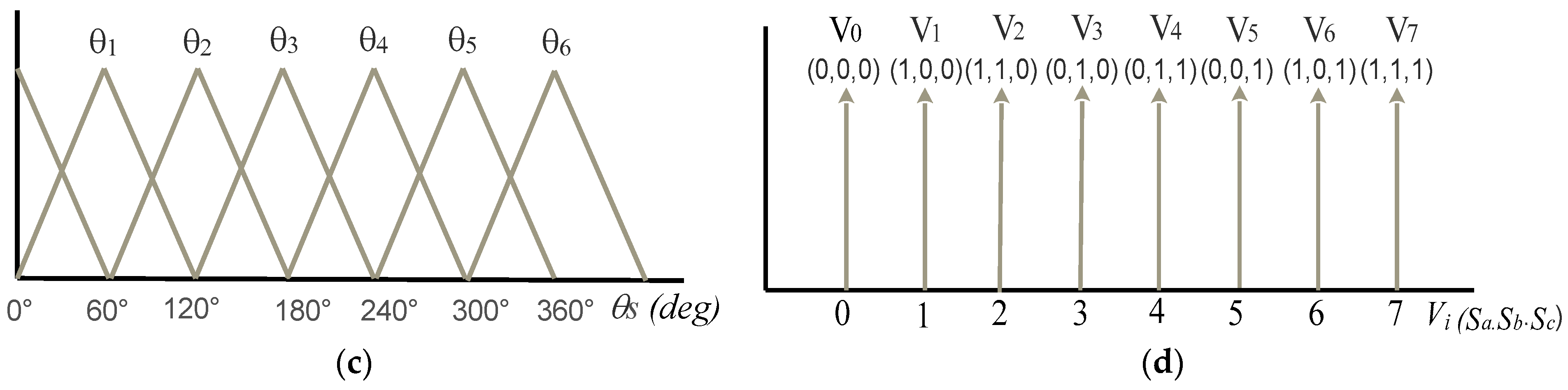
  • For stator flux angle. The stator flux angle ( θ s ) can be divided into six linguistic variables ( θ 1 to θ 6 ) inspired by the six sectors of the sector selector. As shown in Figure 7c, the six variables are represented by isosceles triangular MFs.

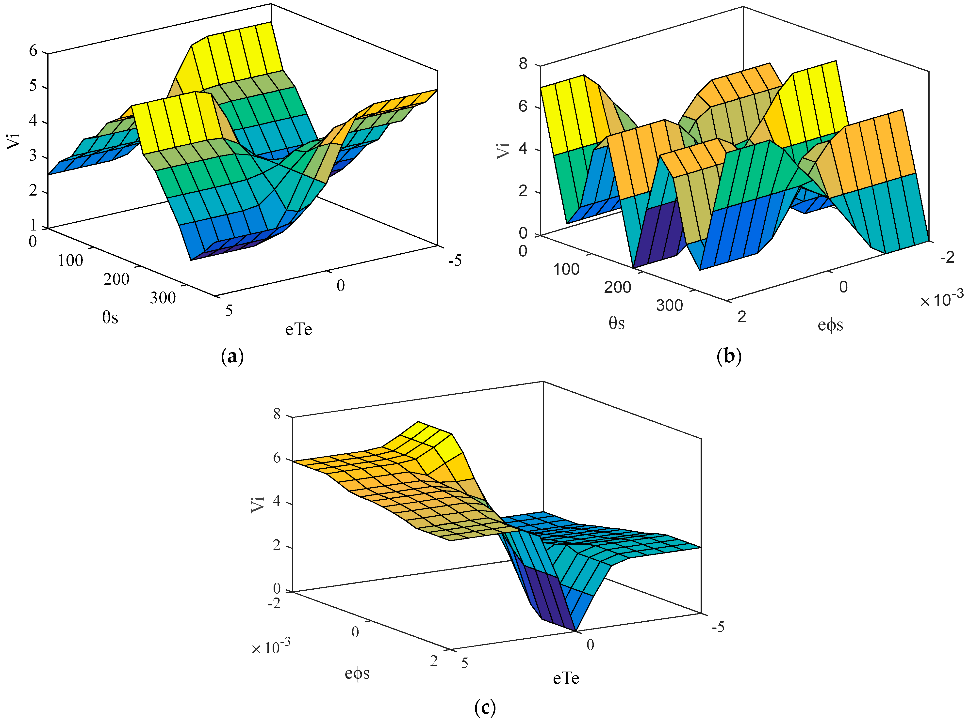
3.2.2. Fuzzy Control Rules

The fuzzy logic rules are designed and presented in Table 5. These rules are inspired by the DTC switching table. A total of 36 fuzzy rules (3 × 2 × 6) were determined based on the membership functions for three inputs and are used to select the appropriate switching state. The Mamdani inference procedure was used to perform the proposed FLC. The weight factor α i for ith rule can be written as [10]:
α i = min ( μ A i ( e T e ) , μ B i ( e ϕ s ) , μ C i ( e θ s ) )
μ V i ( V ) = max ( α i , μ V i ( V ) )
where μ A i ( e T e ) is the membership values of torque error, μ B i ( e ϕ s ) is the membership values of stator flux, and μ C i ( e θ s ) is the membership values of flux angle.

3.2.3. Defuzzification

During this step, the resulting fuzzy sets are converted to real values using the Max method given by Equation (27) as shown in Figure 7d. The selected voltage vector Vi (i: 0,…7) at the output of FLC is converted into switching signals (Sa, Sb, Sc) using the Boolean expression (0 or 1) given by [10]. The resulting fuzzy direct torque control scheme for PMSM in EV systems is presented in Figure 8, and the surfaces of the fuzzy logic controller are shown in Figure 9.
μ V o u t ( V ) = max n = 1 36 ( μ V i ( V ) )
where μ V o u t ( V ) is the membership value of fuzzified output.

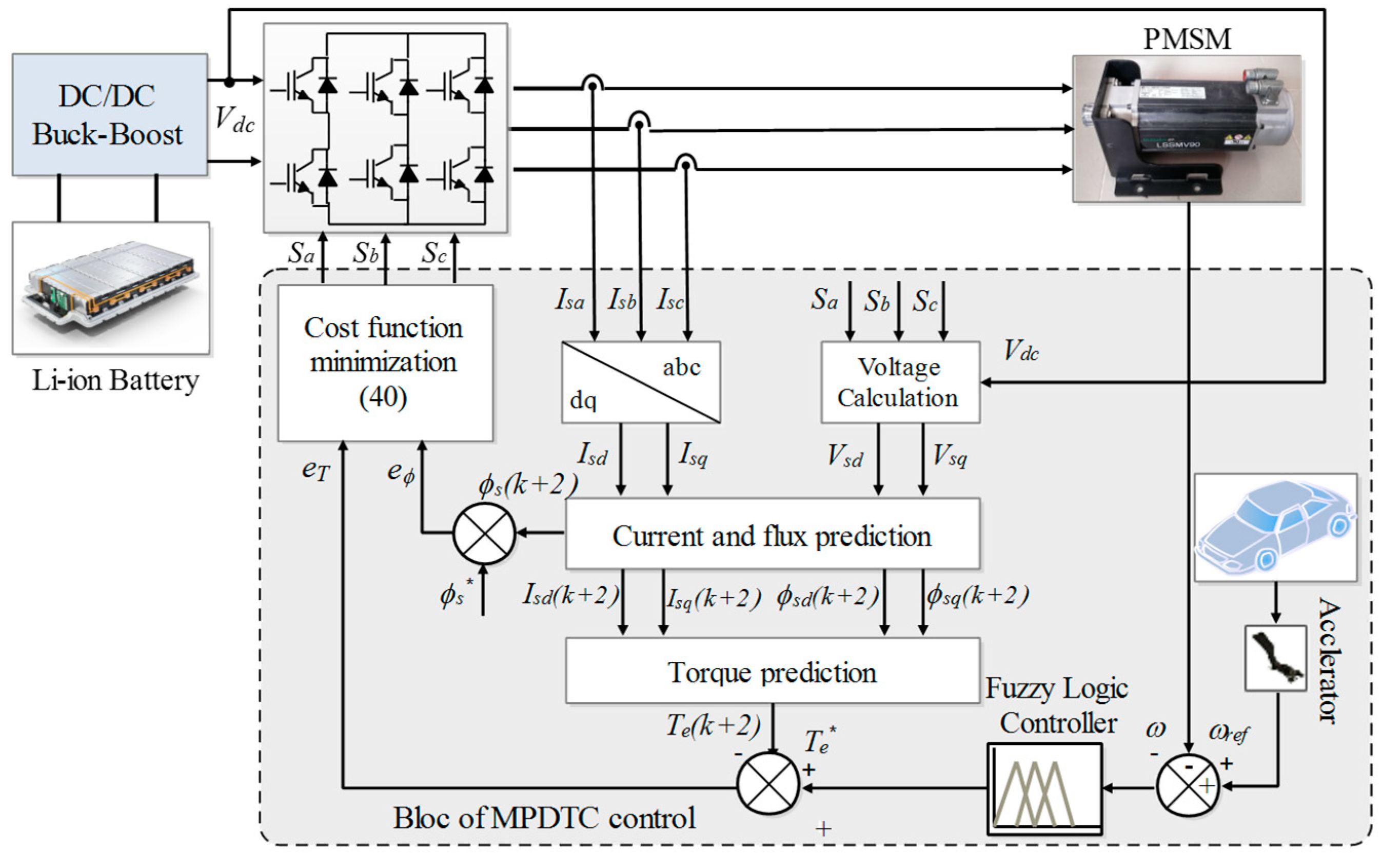
3.3. Model Predictive Direct Torque Control (MPDTC)

Figure 10 depicts the block diagram of the proposed MPDTC strategy, while Figure 11 shows its flowchart. The MPDTC control strategy is based on predicting the future behavior of the system over time using an electric motor model [8]. The numerical implementation of MPDTC for a PMSM in an EV is based on a discrete-time model. This allows the predictive control algorithm to perform its calculations during the system’s operation and use the results obtained for the next control cycle. Furthermore, the MPDTC feature enables the prediction of future-sampled variables whenever they are needed during the numerical calculation of the currents/voltages that will be applied for the next sampling time.
In this work, the MPDTC strategy is designed to control the torque and flux of the PMSM in the electric vehicle system simultaneously. The numerical implementation of the MPDTC algorithm is divided into two main stages. Firstly, control variables are defined, and secondly, the voltage vector to be applied at the next sampling time is selected. To achieve the objectives of reducing fluctuations and achieving the desired control outcomes, a cost function is established to identify the optimal voltage vector based on the minimum error. The forward Euler approximation is used to predict control variables in the MPDTC system [23].

3.3.1. Current, Flux and Torque Predictions

Equations (28) and (29) are used to predict the stator current in discrete time steps. Additionally, Equations (30)–(32) can be used to predict the stator flux in the d-q frame, and the electromagnetic torque can be calculated based on the predicted current and flux values using Equation (33) [42].
I s d ( k + 1 ) = ( 1 R s T s L s d ) I s d ( k ) + ω ( k ) L s q T s L s d I s q ( k ) + T s L s d V s d ( k )
I s q ( k + 1 ) = ( 1 R s T s L s q ) I s q ( k ) ω ( k ) L s d T s L s q I s d ( k ) ω ( k ) ϕ f T s L s q + T s L s q V s q ( k )
ϕ s d ( k + 1 ) = L s d I s d ( k + 1 ) + ϕ f
ϕ s q ( k + 1 ) = L s q I s q ( k + 1 )
ϕ s ( k + 1 ) = ( ϕ s d ( k + 1 ) ) 2 + ( ϕ s q ( k + 1 ) ) 2
T e ( k + 1 ) = 3 2 p ( ϕ s d ( k + 1 ) I s q ( k + 1 ) ϕ s q ( k + 1 ) I s d ( k + 1 ) )

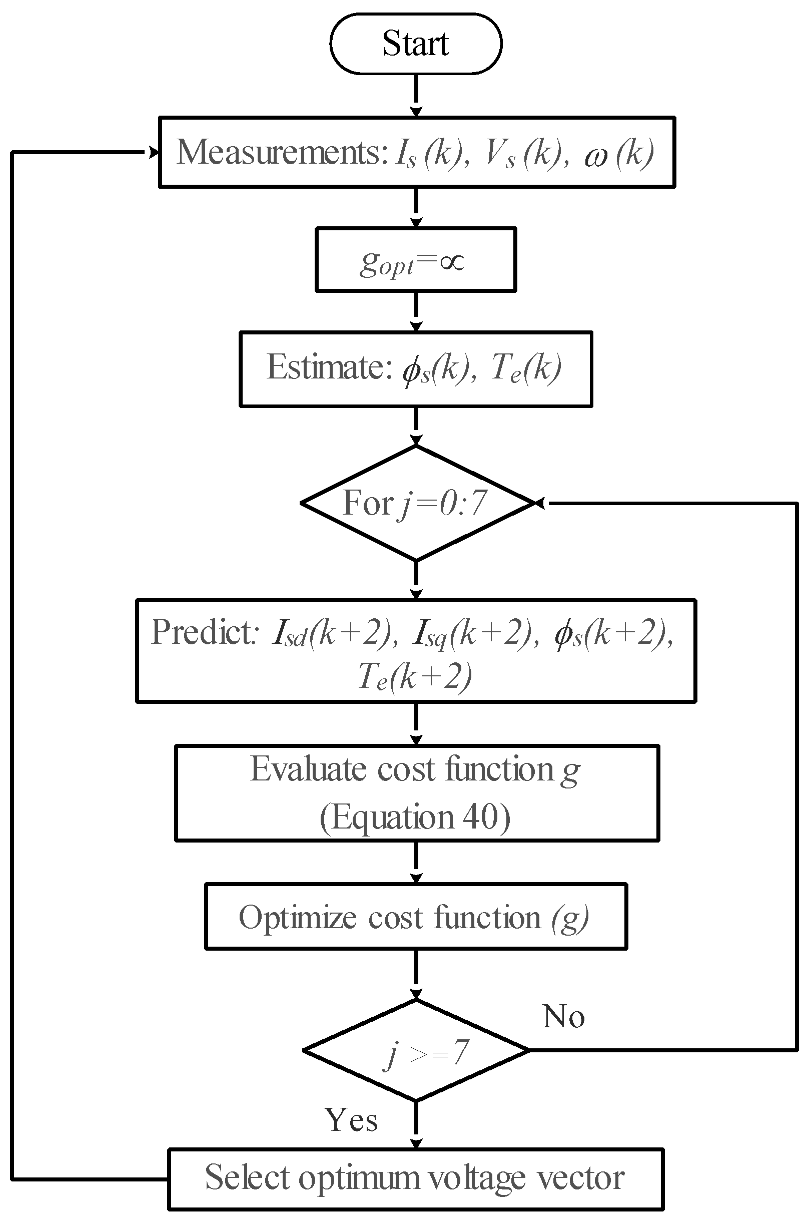
3.3.2. Cost Function Minimization

To ensure optimal control of flux and torque, a cost function is employed. The cost function is defined as a combination of absolute torque and flux error values and is designed to identify the voltage vector that will produce the best control of both variables. The cost function is expressed as follows:
g = | T e T e ( k + 1 ) | + γ | ϕ s ϕ s ( k + 1 ) |
where T e and ϕ s represent the reference values of torque and stator flux, respectively. T e ( k + 1 ) and ϕ s ( k + 1 ) represent the predicted values of torque and stator flux at the next time step, respectively. The weighting factor γ is used to adjust the relative importance of torque and flux control in the cost function.

3.3.3. Time Delay Compensation

Due to a delay resulting from the discrete-time digital implementation, the voltage vector determined by the MPDTC controller cannot be immediately applied. The selected voltage vector at time (k) will be applied at time (k + 1) with a delay of one step. This delay is due to the very short sampling time. This can negatively impact the performance of the system. To improve these performances, compensation for the delay time must be carried out. As a result, two-step-ahead prediction (k + 2) will be considered. Equations (35)–(38) can be used to express the stator currents, stator flux, and electromagnetic torque at time (k + 2). Additionally, to prevent overcurrent, the cost function g can be extended by adding a current magnitude limitation term defined in Equation (39) [7,36,40].
I s d ( k + 2 ) = ( 1 R s T s L s d ) I s d ( k + 1 ) + ω ( k + 1 ) L s q T s L s d I s q ( k + 1 ) + T s L s d V s d ( k + 1 )
I s q ( k + 2 ) = ( 1 R s T s L s q ) I s q ( k + 1 ) ω ( k + 1 ) L s d T s L s q I s d ( k + 1 ) ω ( k + 1 ) ϕ f T s L s q + T s L s q V s q ( k + 1 )
ϕ s ( k + 2 ) = ( ϕ s d ( k + 2 ) ) 2 + ( ϕ s q ( k + 2 ) ) 2
T e ( k + 2 ) = 3 2 p ( ϕ s d ( k + 2 ) I s q ( k + 2 ) ϕ s q ( k + 2 ) I s d ( k + 2 ) )
f ( I s d ( k + 2 ) , I s q ( k + 2 ) ) = { i f | I d s ( k + 2 ) | > I max o r | I q s ( k + 2 ) | > I max 0 i f | I d s ( k + 2 ) | I max o r | I q s ( k + 2 ) | I max
Finally, the resulting total cost function g for MPDTC with compensation of the computation time delay is given by Equation (40).
g = | T e 3 2 p ( ϕ s d ( k + 2 ) I s q ( k + 2 ) ϕ s q ( k + 2 ) I s d ( k + 2 ) ) | + γ | ϕ s ( ϕ s d ( k + 2 ) ) 2 + ( ϕ s q ( k + 2 ) ) 2 | + f ( I s d ( k + 2 ) , I s q ( k + 2 ) )

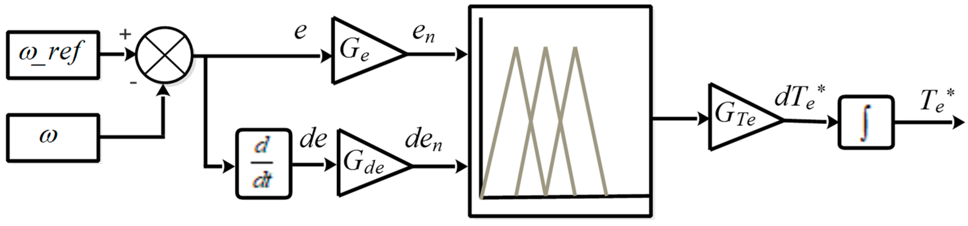
3.4. Fuzzy Logic Speed Control

In this subsection, an FLC is employed to control the speed of the PMSM in the EV system, replacing the conventional PI controller. The fuzzy controller receives two inputs, namely the speed error (e) and its derivative (de), and generates one output, which is the reference torque (Te*), as illustrated in Figure 12. Scaling factors are utilized at the input and output of the FLC to adjust its sensitivity while maintaining its structure [43,44]. The speed error (e) and its derivative (de) are normalized before being fed into the FLC, and are expressed as follows:
{ e n = G e · e d e n = G d e · d e
In this work, the speed error, its derivative, and the reference torque are represented as fuzzy sets that are divided into seven categories: “Large negative” (NB), “Medium negative” (NM), “Small negative” (NS), “Zero” (Z), “Small positive” (PS), “Medium positive” (PM), and “Large positive” (PG). The membership functions for these categories are shown in Figure 13 and are used to define the degree to which each input or output variable belongs to each category.
Table 6 represents the fuzzy logic rules corresponding to the fuzzy speed controller. According to this table 49 fuzzy rules (7 × 7) are determined on the basis of two inputs, speed error and derivative speed error to select the appropriate reference torque. Mamdani’s inference procedure was used to perform the speed controller, and the center of gravity method was applied for defuzzification to calculate the proposed controller output.

4. Simulation Results and Discussion

In order to evaluate the efficiency of EVs and to test the dynamic performance of control techniques. The NYCC (New York City Cycle) driving cycle is adopted in this paper. The dynamic performances of the PMSM in the EV system were compared using Matlab/Simulink. To ensure a fair and accurate comparison of results, the tests are conducted with similar initial conditions.

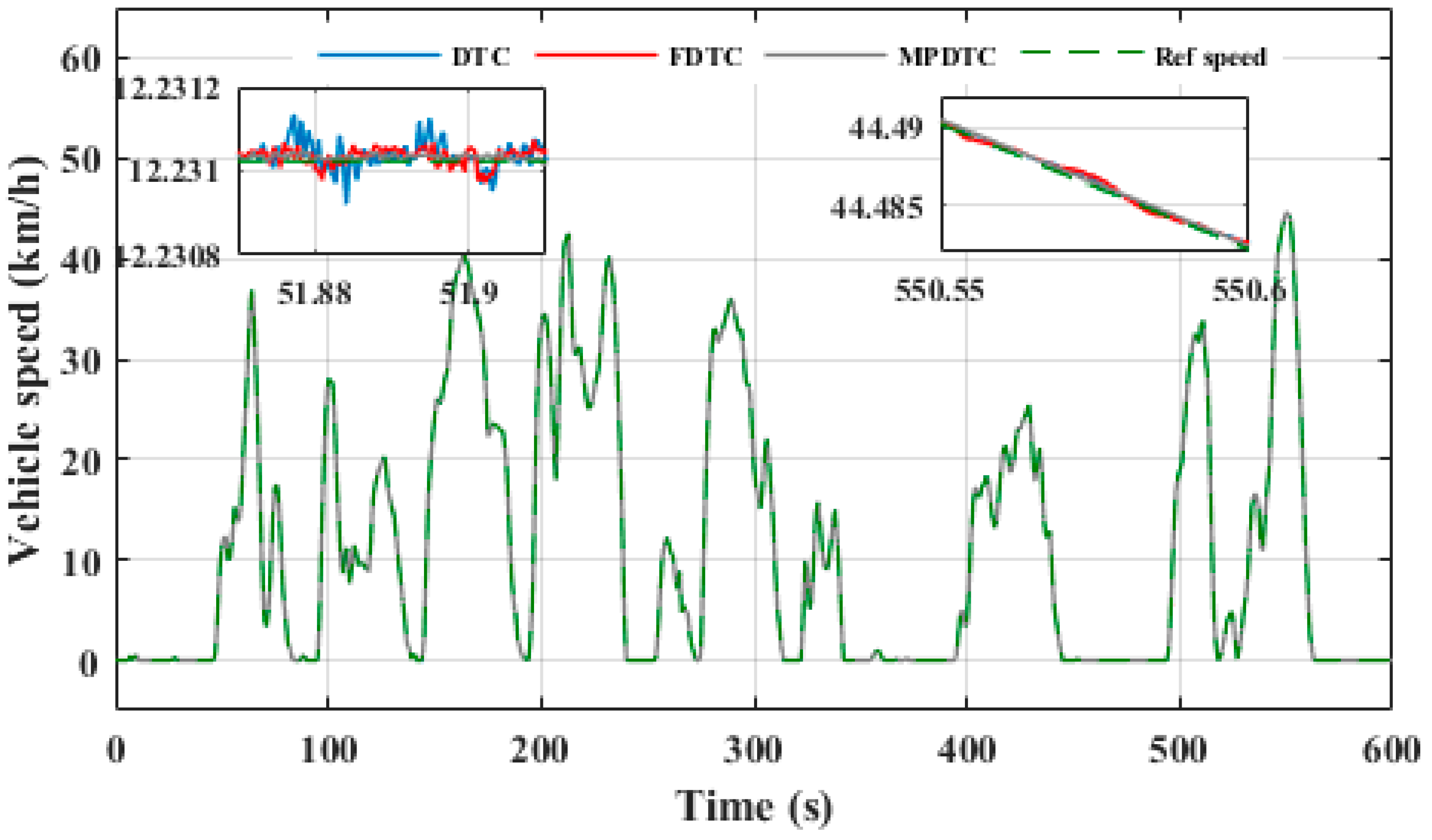
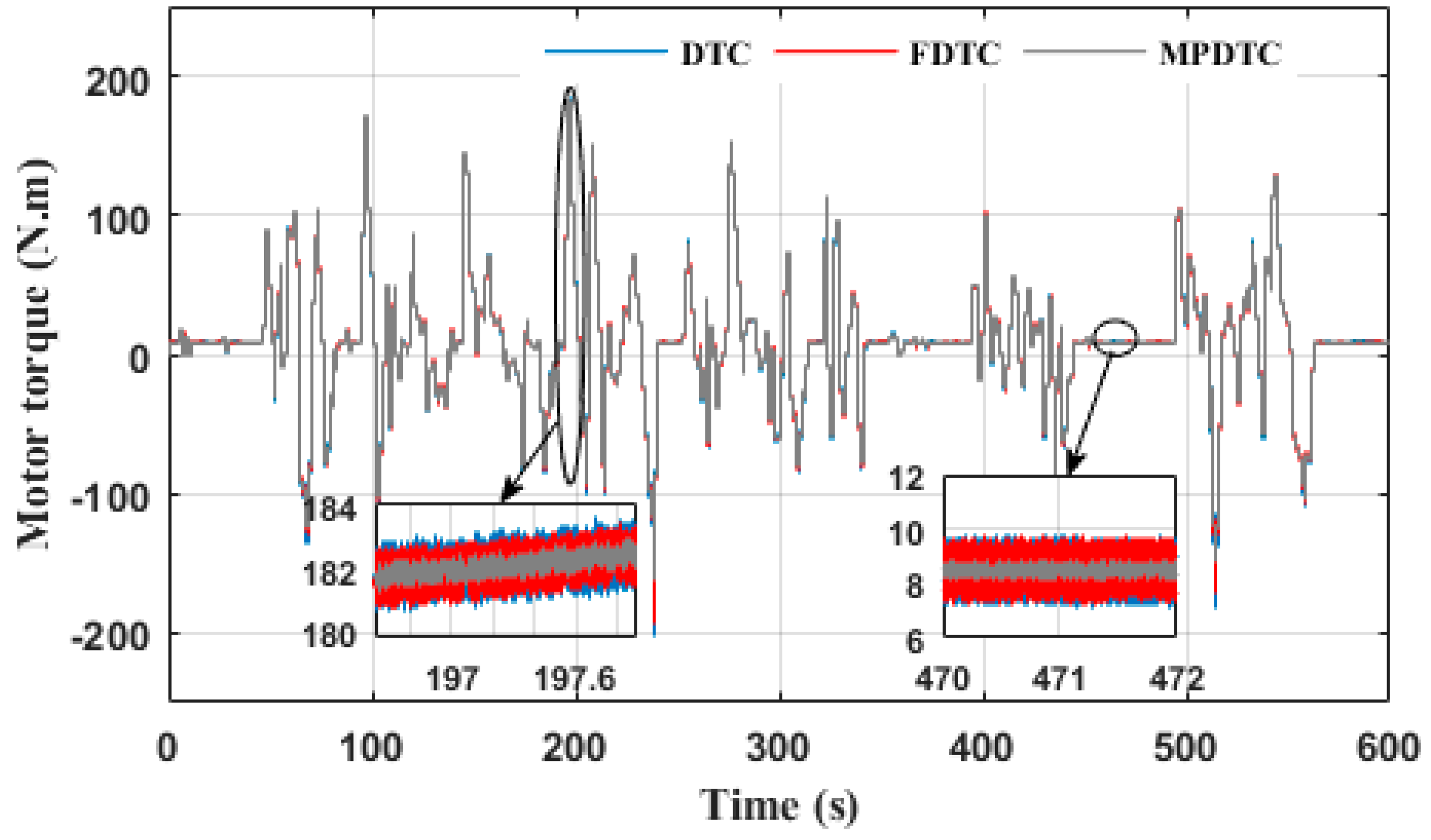
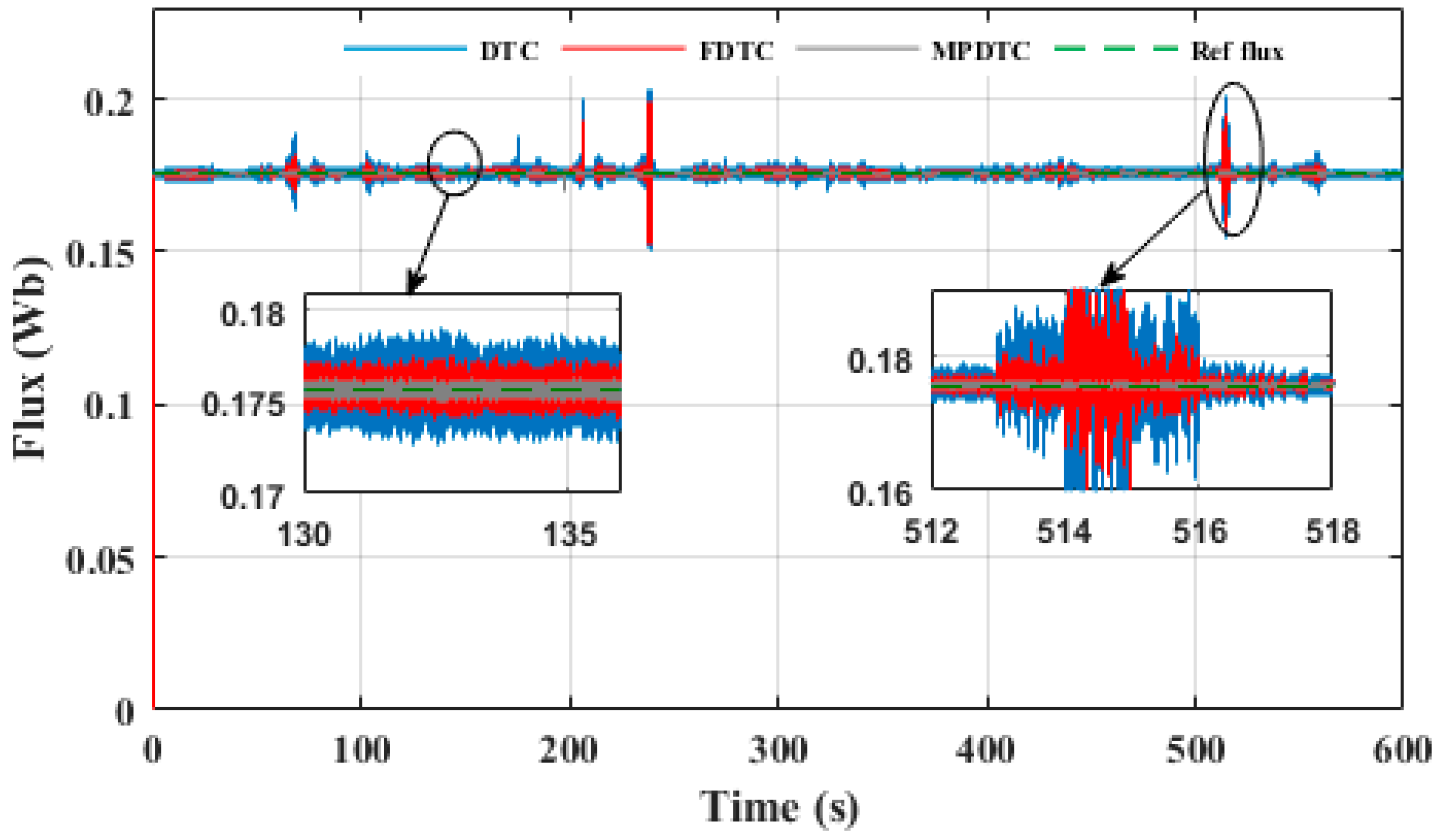
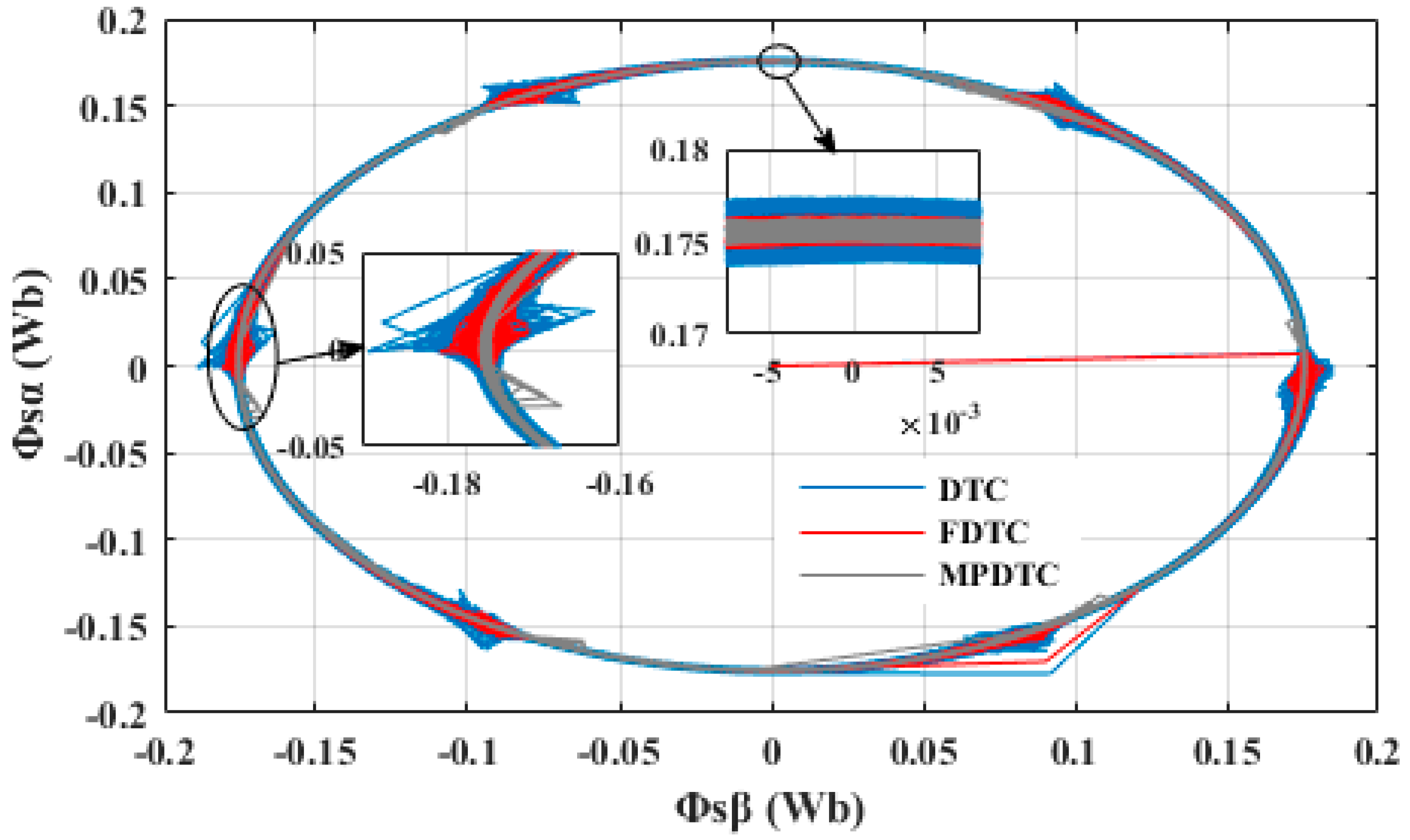
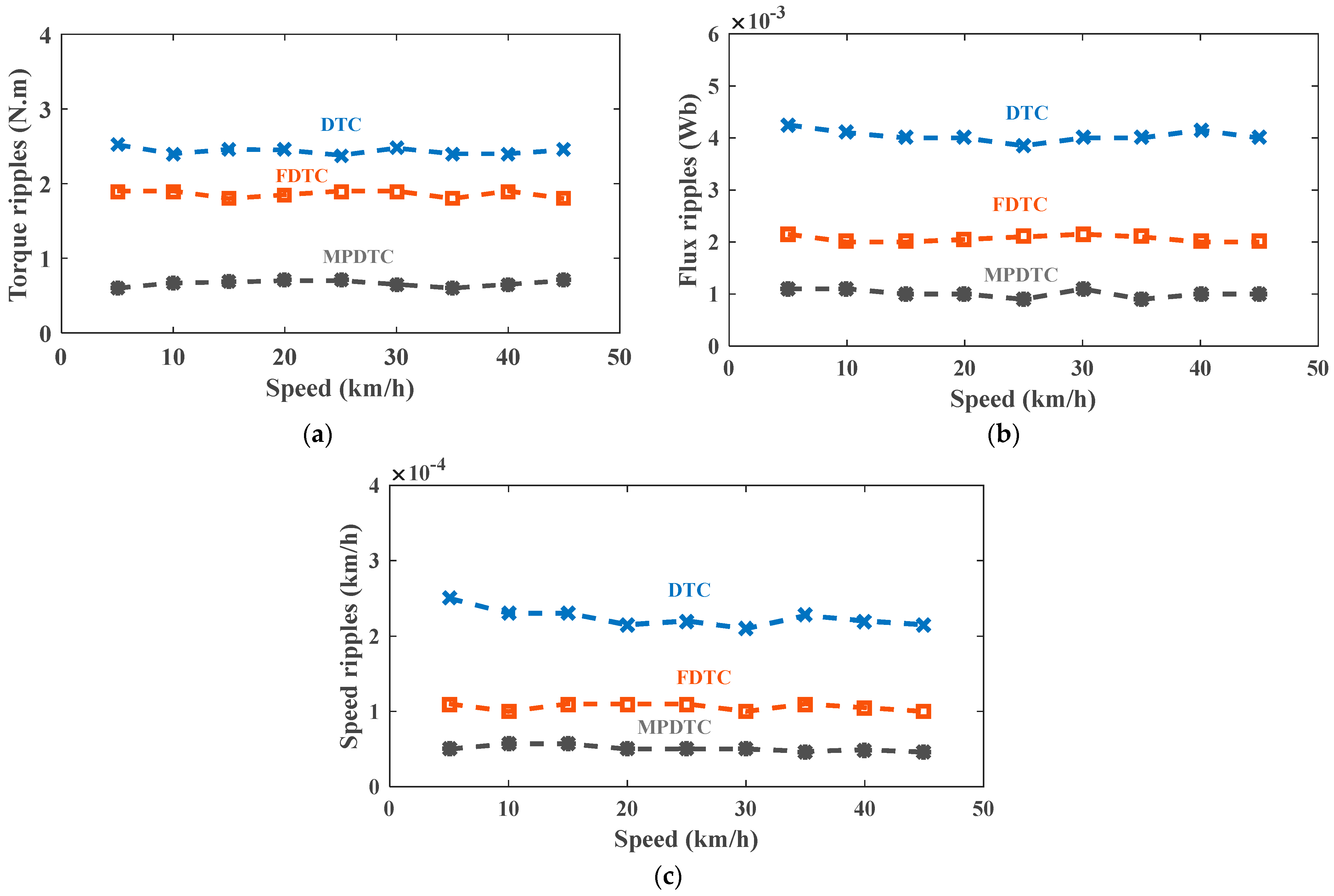
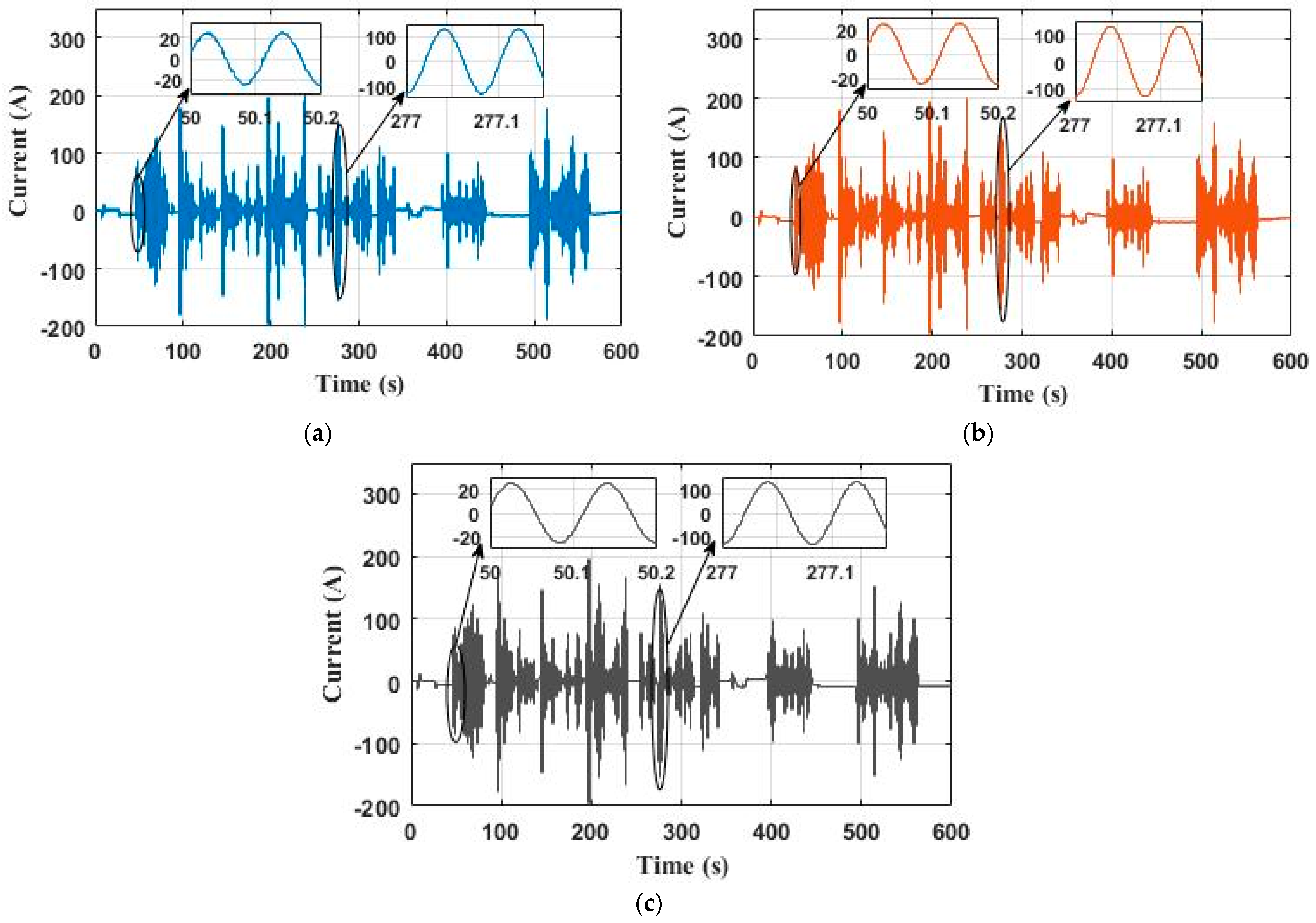
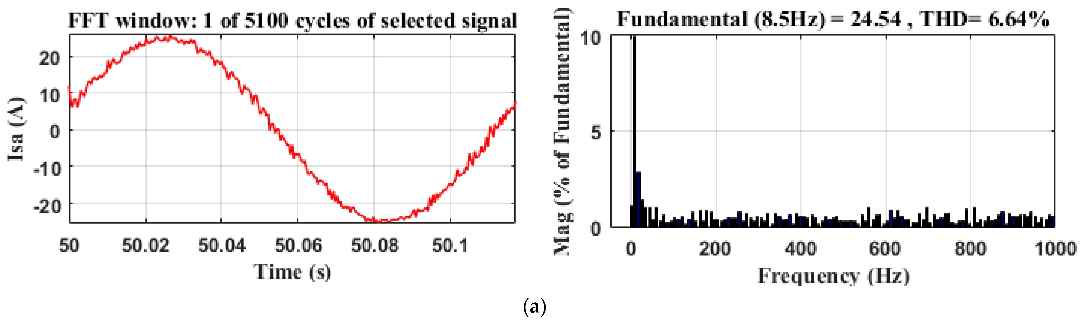
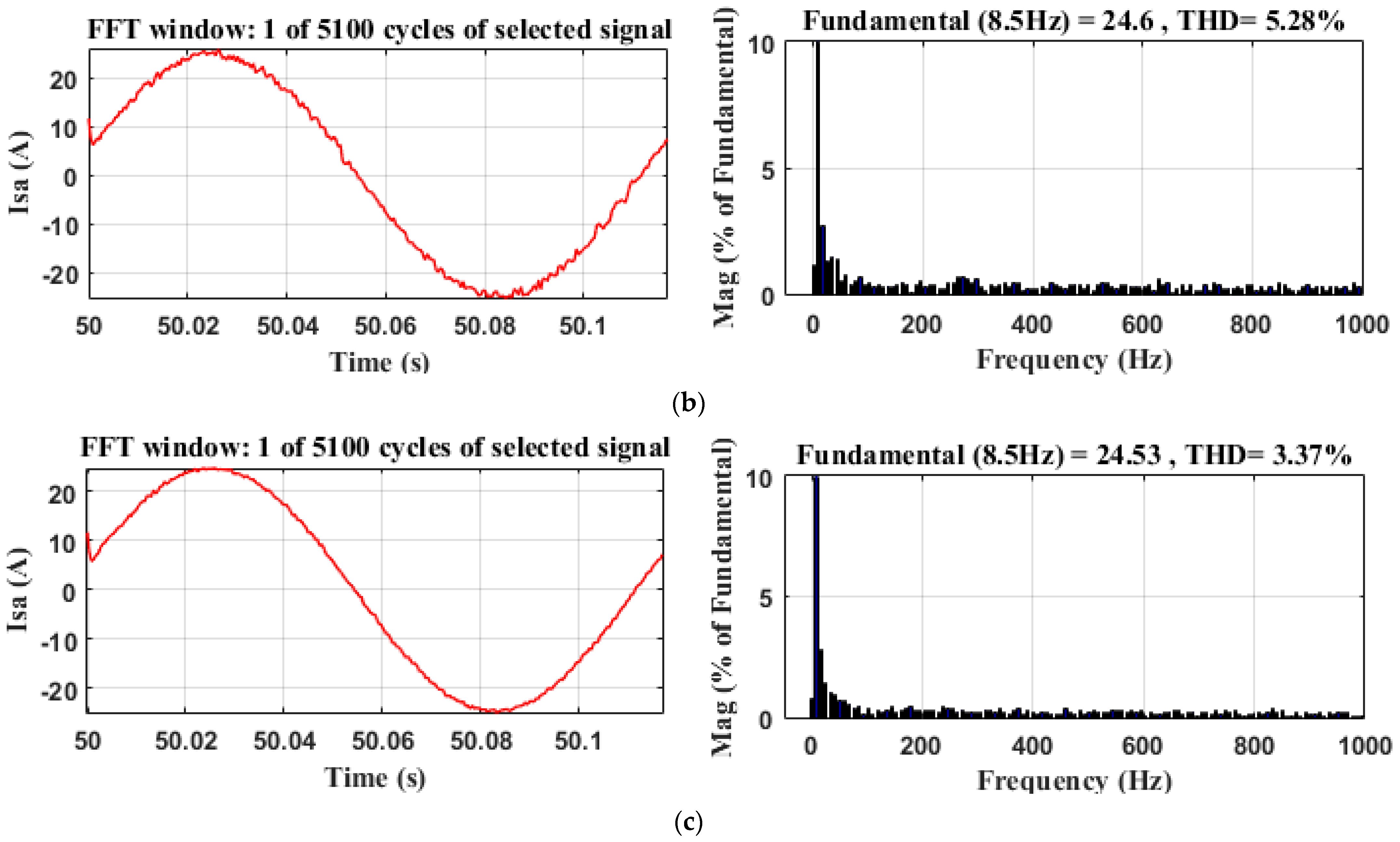
4.1. Comparison between Different Control Techniques

Figure 14 shows the speed of the electric vehicle under different control techniques when the NYCC driving cycle is applied. It can be seen that the vehicle has satisfactory speed tracking capability, but with different responses. The MPDTC technique stands out from the FDTC and DTC techniques for its faster response and lower speed variation. The speed fluctuation of the MPDTC is about 0.5 × 10⁻⁴ km/h, which is lower than that of the conventional DTC, which is about 2.2 × 10⁻⁴ km/h, and that of the FDTC, which is about 1.1 × 10⁻⁴ km/h, presenting an improvement of 77.27% and 50.54% compared to the DTC and FDTC techniques, respectively. In short, these results show that the MPDTC technique offers better speed control performance for the electric vehicle during the NYCC cycle.
Figure 15 depicts the electromagnetic torque of the PMSM using the different control methods. It can be noticed that the torque responses quickly follow the reference torque during all high or low speed trajectories. The three techniques showed remarkable tracking performance. However, significant torque ripples of about 2.4 N·m are observed in the case of conventional DTC while FDTC and MPDTC control strategies present lower ripples around 1.9 N·m and 0.65 N·m, respectively. The MPDTC technique reduces torque ripples by 72.92% and 65.78% compared to the DTC and FDTC techniques, respectively.
Figure 16 shows the stator flux of PMSM in the EV system using different control techniques. It can be observed that the measured stator flux follows its reference with different precision for each control technique. The MPDTC technique has a minimal stator flux ripple of 0.001 Wb, which is lower than that observed in the classical DTC and FDTC techniques, which are 0.004 Wb and 0.002 Wb, respectively. Thus, the MPDTC technique offers a significant improvement compared to other techniques, with a reduction of 75% and 50% compared to DTC and FDTC, respectively.
Figure 17 shows the stator-flux loci. It can be seen that, for all three control techniques considered, the flux adopts a circular shape with constant amplitude. However, the MPDTC technique has the best shape with a smoother and regular stator-flux locus, followed by the FDTC technique and then the DTC technique.
The values of the torque, flux, and speed ripples in the DTC, FDTC, and MPDTC control techniques are shown in Figure 18 for various speed values. It is clearly observed that the MPDTC control technique significantly reduces the torque, flux, and speed ripples compared to the DTC and FDTC techniques. These results demonstrate the effectiveness of the MPDTC technique for reducing disturbances in the control systems of PMSMs.
Figure 19a–c shows the current of one phase for each control technique. It can be noticed that the stator current is perfectly sinusoidal, and its dynamic variation corresponds to the changes of speed and load torque. In Figure 19c, it can be seen that the MPDTC technique has the fastest current response compared to the one of classical DTC in Figure 19a, and that of FDTC in Figure 19b.
Figure 20a–c shows the fast Fourier transform (FFT) analyses of the phase current and the calculation of THD for the three control strategies. The stator current THD of MPDTC is 3.37%, which is lower than that of the classical DTC, which is 6.64%, and that of FDTC, which is 5.28%, presenting an improvement of 49.24% and 36.17% compared to the DTC and FDTC techniques, respectively.
The simulation results presented in Table 7 demonstrate that the MPDTC control technique has effectively reduced the flux and torque ripples, as well as the THD of the PMSM current, when compared to the DTC and FDTC techniques. These results reinforce the superiority of the MPDTC technique in terms of performance and confirm its effectiveness.

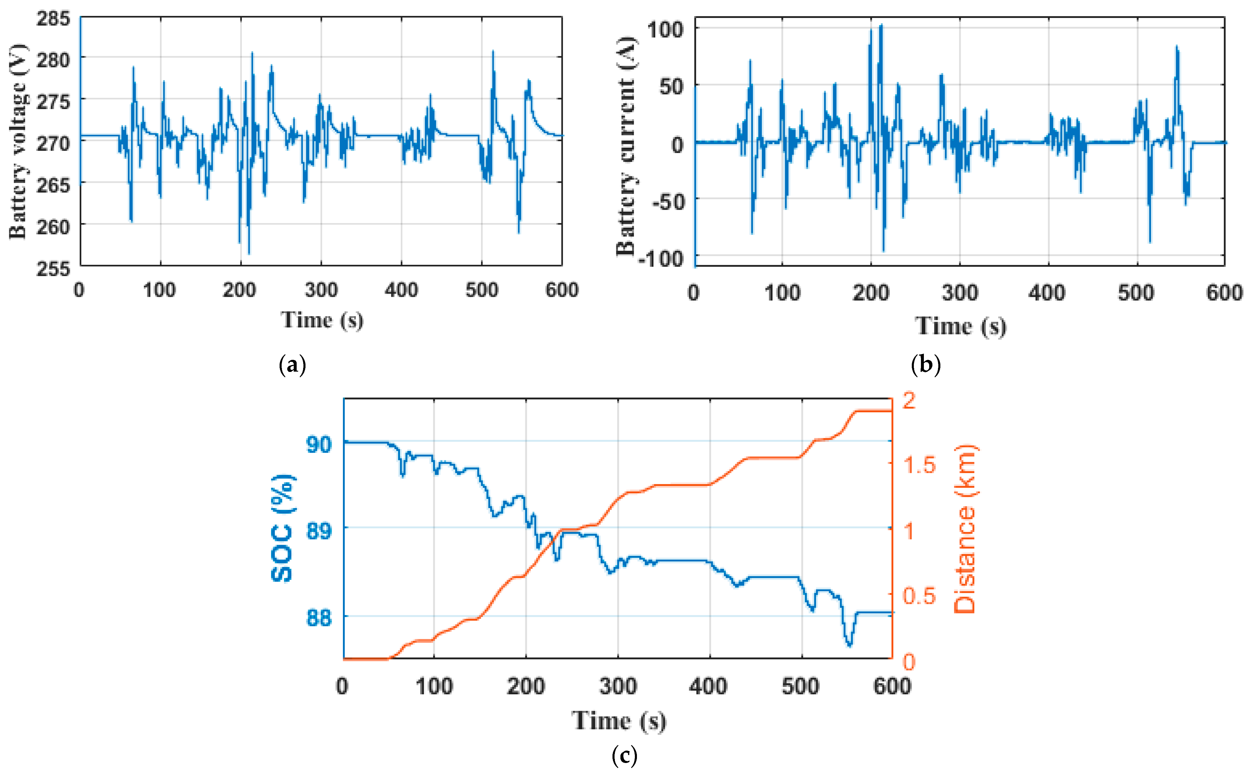
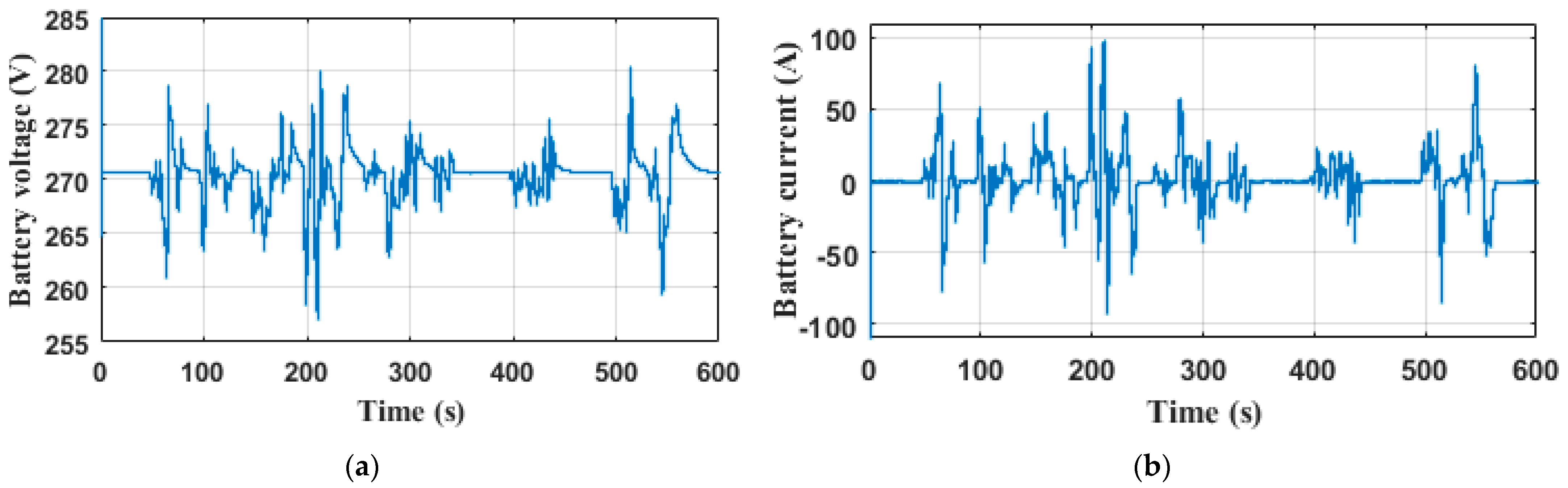
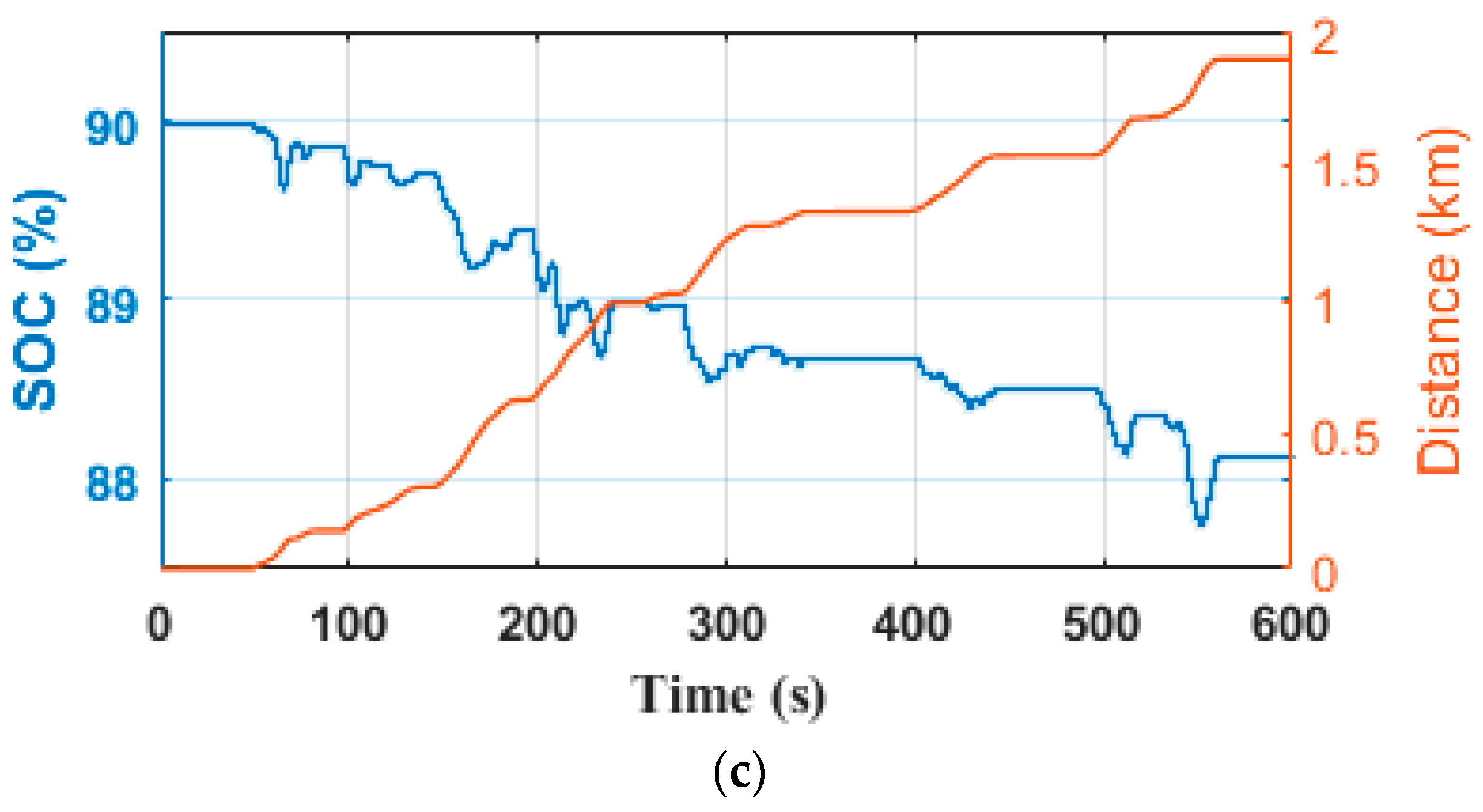
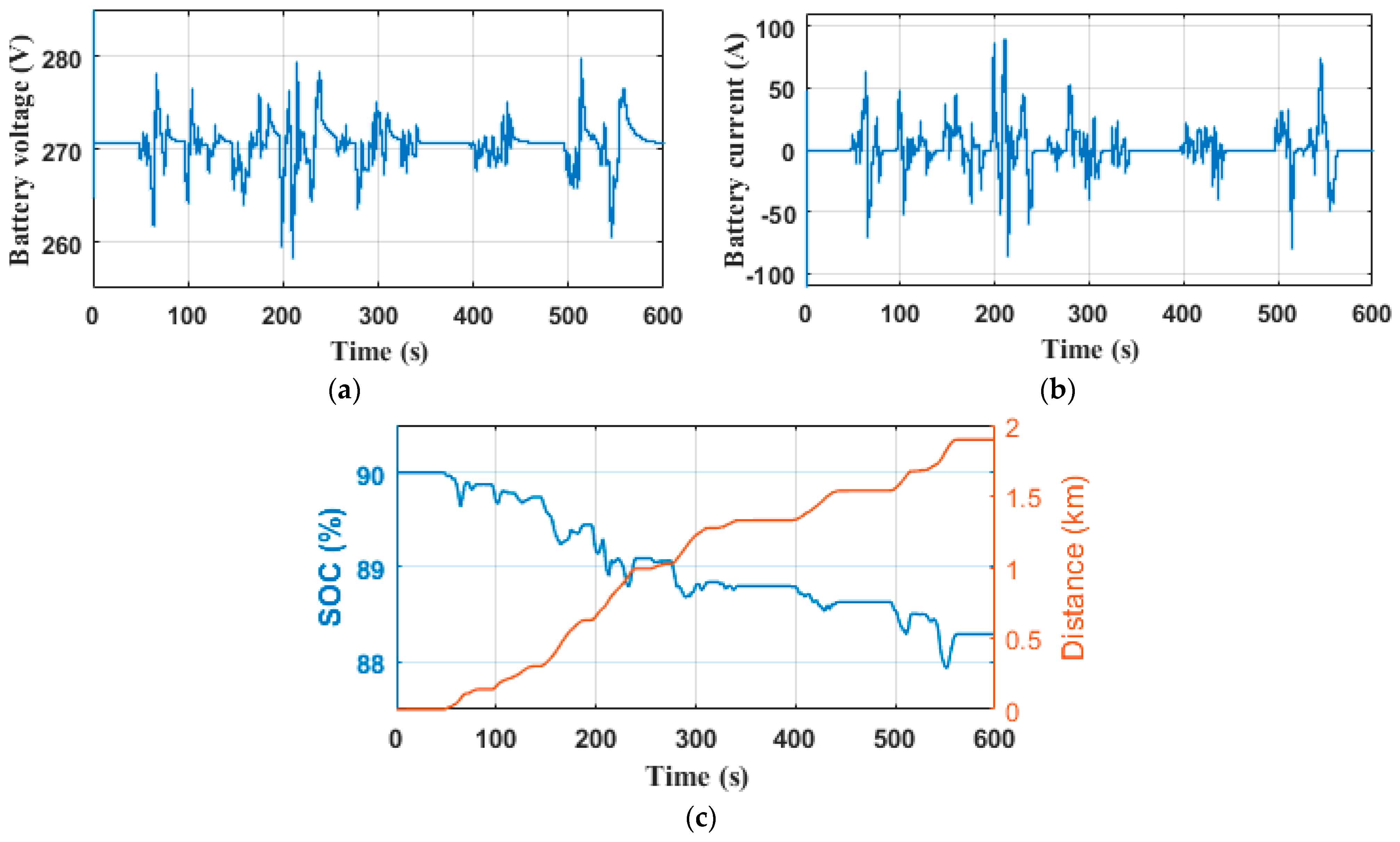
4.2. Dynamic Performance of the Battery for DTC, FDTC and MPDTC

The voltage, current, state of charge of the Li-ion battery, and the distance covered during the operating time under the NYCC driving cycle for the DTC, FDTC, and MPDTC strategies are shown in Figure 21a–c, Figure 22a–c and Figure 23a–c, respectively. The Li-ion battery voltage varies between 279.5 V and 256.5 V for the DTC technique (Figure 21a) between 279 V and 257.2 V for the FDTC technique (Figure 22a), and between 278 V and 258.5 V for the MPDTC technique (Figure 23a). MPDTC reduces the voltage deviation by 15.22% compared to the DTC and 10.55% compared to the FDTC. The Li-ion battery current oscillates between −76 A and 103 A for DTC (Figure 21b), between −72 A and 98 A for FDTC (Figure 22b), and between −66 A and 90 A for the MPDTC strategy (Figure 23b). The MPDTC reduces the current deflection by 24.27% and 8.24% compared to the DTC and FDTC techniques, respectively. The trajectory of the Li-ion battery SOC with NYCC cycle driving distance is recorded with an initial SOC of 90%. At the end of the driving cycle, the vehicle has covered 1.89 km and the final Li-ion battery SOC values are 88.056%, 88.138%, and 88.293% for the DTC, FDTC, and MPDTC techniques, respectively. According to these results, in one charging cycle, the vehicle can travel approximately 97.22 km with the DTC technique, 101.50 km with the FDTC technique, and up to 110.72 km with the MPDTC technique.

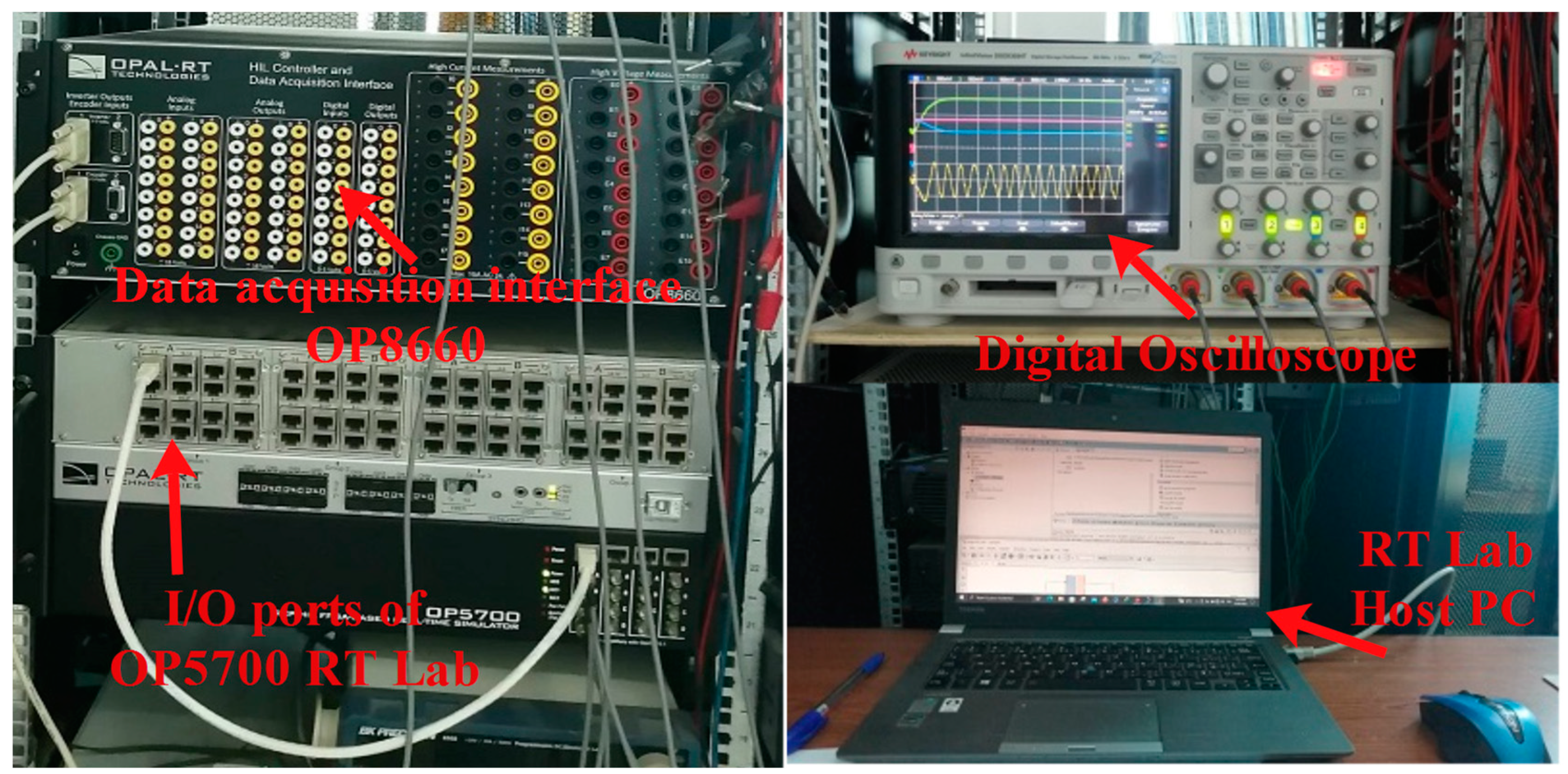
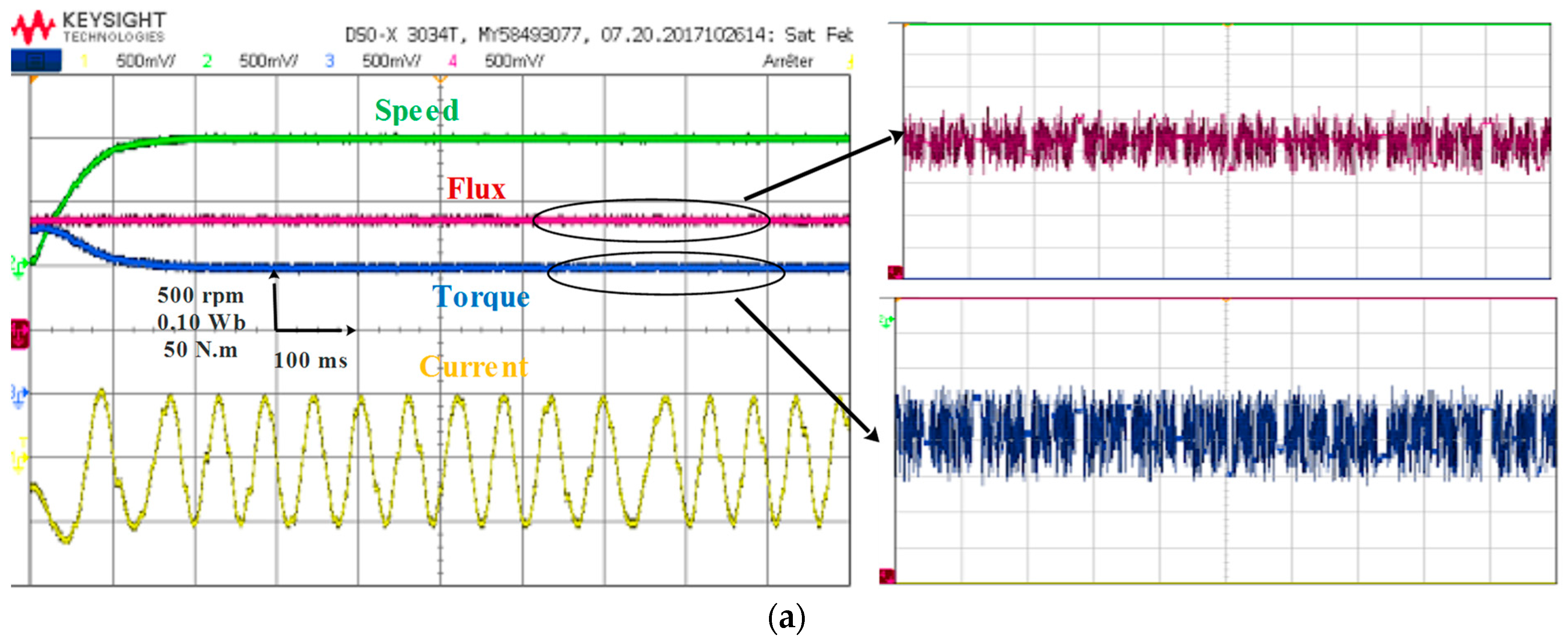
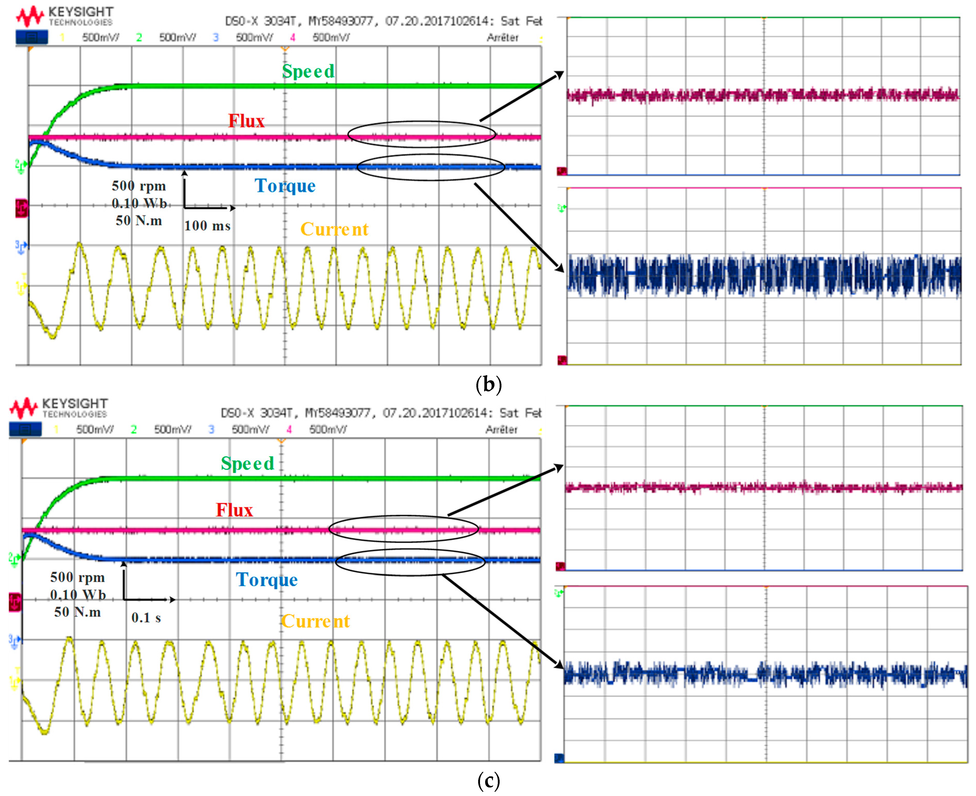
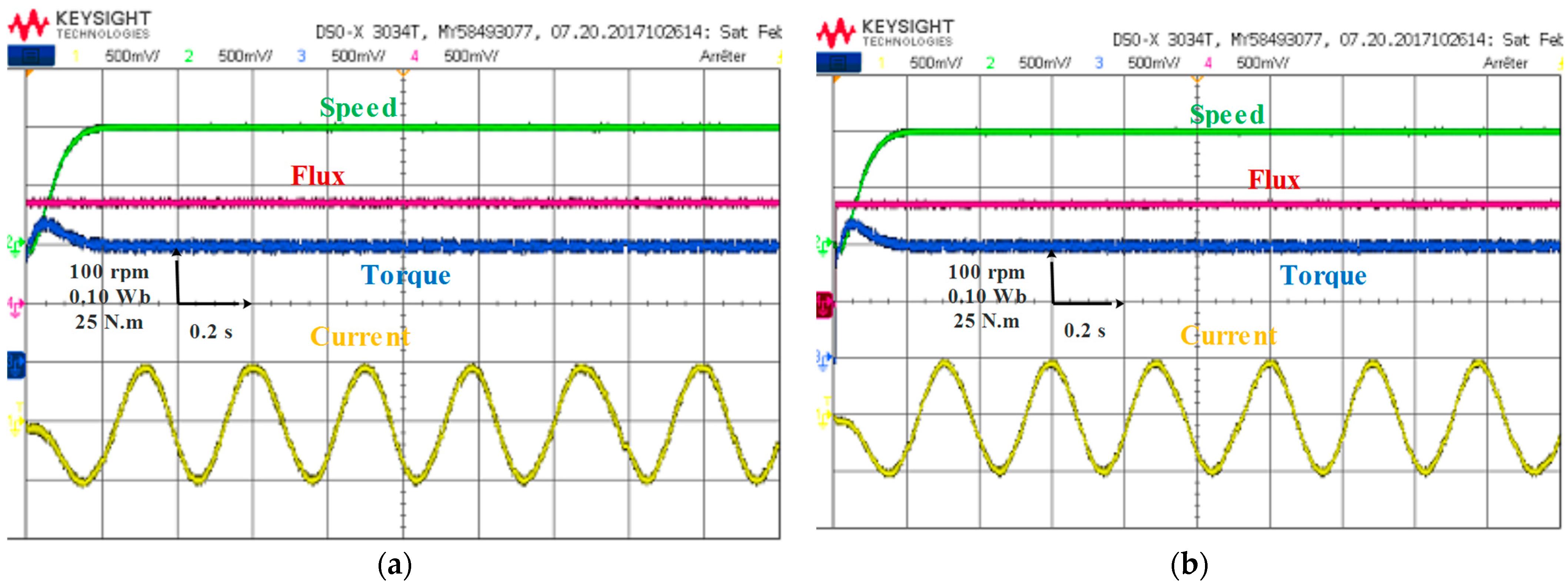
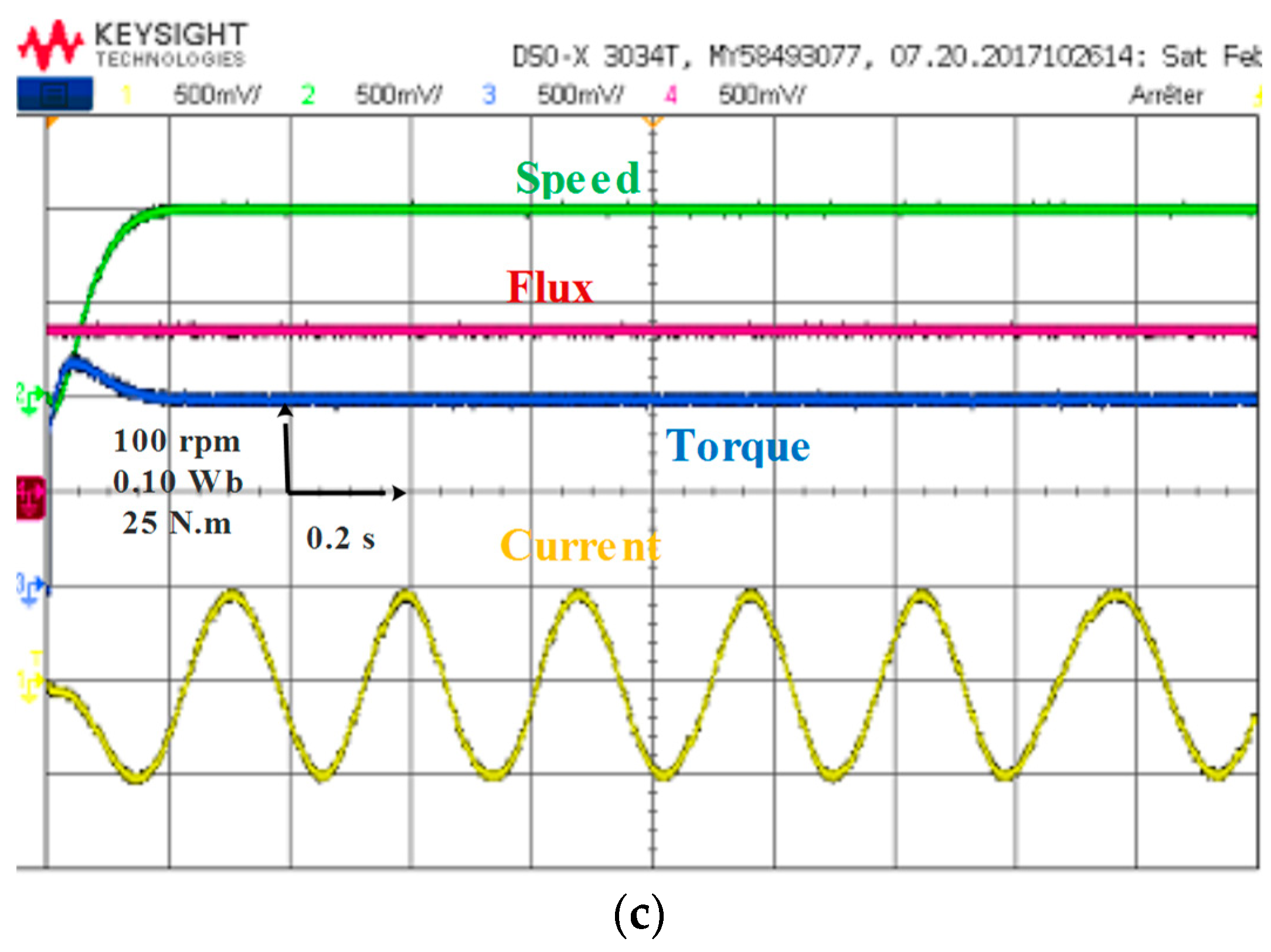
5. Real-Time Platform Using RT-LAB

To validate the effectiveness of proposed control algorithms, a series of experimental tests were conducted on a real-time simulator RT Lab. The MPDTC control technique, as well as other studied techniques, were executed. The system parameters were kept the same as those used in the numerical simulation carried out with Matlab/Simulink. Figure 24 illustrates the real-time simulation bench installed at the LTII laboratory, University of Bejaia, Algeria. It is composed of a host PC, a real-time digital simulator OP5700, an HIL controller, an OP8660 data acquisition interface, and a digital oscilloscope.
Performance analysis of conventional DTC, FDTC, and MPDTC control strategies was carried out in the form of a comparative evaluation. The figures present the results obtained for different operating tests, including steady-state behavior, low-speed operation, and torque response to load application.
Figure 25a–c shows the steady-state behavior of the three control techniques at a speed of 1000 rpm and a load of 100 N·m. The zoomed in sections on the figures show the flux and torque ripples. The results show that all three control techniques allow for good speed tracking. However, significant torque and flux ripples, as well as current harmonics, are observed under the conventional DTC control technique. On the other hand, MPDTC presents better current quality, with less torque and flux ripples than the other techniques.
Figure 26a–c compares the performance when operating conditions are a speed of 200 rpm and a torque of 50 N·m. In Figure 26a, it can be observed that the DTC technique presents significant fluctuations in torque and flux, as well as current harmonics. At low speed, this technique can cause rapid variations in torque and flux, which can be difficult to precisely control, resulting in machine instability and decreased torque performance. On the other hand, the FDTC and MPDTC techniques show good performance in the low-speed region. The results in Figure 26b,c shows that these techniques present a more stable and precise control performance at low speed than the DTC technique.
The performance of the three strategies was evaluated when the torque reference step changes from 30 to 100 Nm, as illustrated in Figure 27a–c. The results show that the torque follows its reference trajectory for all three control strategies, with almost similar responses. This observation can be explained by the use of the same fuzzy controller for the external speed loop in all control strategies. The settling time for DTC and FDTC is approximately 0.155 s, and it is approximately 0.145 s for MPDTC.
In summary, the tests conducted in this section demonstrate that the MPDTC control technique significantly reduces torque and flux ripples and improves the quality of the current. Additionally, this method offers a faster dynamic response. The results obtained using a real-time discrete-simulator RT LAB prove the superiority of the MPDTC technique over conventional DTC and FDTC techniques.

6. Conclusions

This research work presents a detailed analysis and comparative study of three control torque structures for a permanent magnet synchronous motor in electric vehicles. These control strategies are the DTC, FDTC, and MPTDC, all of which were designed and developed to meet the requirements of the vehicle. The simulation results were validated through numerical simulation using MATLAB/Simulink and real-time simulation using the RT LAB simulator. The obtained results show that the MPTDC is the most effective control strategy for controlling the PMSM in an electric vehicle. This strategy reduced torque and flux ripples, decreased the total harmonic distortion of the PMSM current, and provided a faster transient response compared to the DTC and FDTC techniques. Additionally, the MPTDC technique enabled the electric vehicle to cover the longest distance of about 110.72 km in a charging cycle. Therefore, the MPTDC technique is a powerful candidate for PMSM control in electric vehicles.

Author Contributions

Conceptualization, K.K. and T.R.; methodology, K.K., A.O., S.M. and T.R.; software, K.K.; validation, K.K., A.O. and T.R.; formal analysis, K.K., A.O., S.M., D.R. and T.R.; investigation, K.K., A.O., S.M., D.R. and T.R.; resources, K.K. and T.R.; data curation, K.K., A.O., S.M., D.R. and T.R.; writing—original draft preparation, K.K.; writing—review and editing, K.K., A.O., S.M., D.R. and T.R.; visualization, K.K., S.M. and T.R.; supervision, S.M. and T.R.; project administration, T.R.; funding acquisition, T.R. and S.M. All authors have read and agreed to the published version of the manuscript.

Funding

This research received no external funding.

Data Availability Statement

Not applicable.

Conflicts of Interest

The authors declare no conflict of interest.

References

  1. Pamuła, T.; Pamuła, W. Estimation of the Energy Consumption of Battery Electric Buses for Public Transport Networks Using Real-World Data and Deep Learning. Energies 2020, 13, 2340. [Google Scholar] [CrossRef]
  2. Andwari, A.M.; Pesiridis, A.; Rajoo, S.; Martinez-Botas, R.; Esfahanian, V. A Review of Battery Electric Vehicle Technology and Readiness Levels. Renew. Sustain. Energy Rev. 2017, 78, 414–430. [Google Scholar] [CrossRef]
  3. Makrygiorgou, J.J.; Alexandridis, A.T. Power Electronic Control Design for Stable EV Motor and Battery Operation during a Route. Energies 2019, 12, 1990. [Google Scholar] [CrossRef] [Green Version]
  4. Pellegrino, G.; Vagati, A.; Boazzo, B.; Guglielmi, P. Comparison of Induction and PM Synchronous Motor Drives for EV Application Including Design Examples. IEEE Trans. Ind. Appl. 2012, 48, 2322–2332. [Google Scholar] [CrossRef] [Green Version]
  5. Mokrani, Z.; Rekioua, D.; Mebarki, N.; Rekioua, T.; Bacha, S. Proposed energy management strategy in electric vehicle for recovering power excess produced by fuel cells. Int. J. Hydrog. Energy 2017, 42, 19556–19575. [Google Scholar] [CrossRef]
  6. Zhang, Z.; Ge, X.; Tian, Z.; Zhang, X.; Tang, Q.; Feng, X. A PWM for Minimum Current Harmonic Distortion in Metro Traction PMSM with Saliency Ratio and Load Angle Constrains. IEEE Trans. Power Electron. 2017, 33, 4498–4511. [Google Scholar] [CrossRef]
  7. Li, G.; Hu, J.; Li, Y.; Zhu, J. An Improved Model Predictive Direct Torque Control Strategy for Reducing Harmonic Currents and Torque Ripples of Five-Phase Permanent Magnet Synchronous Motors. IEEE Trans. Ind. Electron. 2018, 66, 5820–5829. [Google Scholar] [CrossRef]
  8. Wang, Z.; Chen, J.; Cheng, M.; Chau, K.T. Field-Oriented Control and Direct Torque Control for Paralleled VSIs Fed PMSM Drives with Variable Switching Frequencies. IEEE Trans. Power Electron. 2015, 31, 2417–2428. [Google Scholar] [CrossRef]
  9. Emanuele, G.; Marco, P.; Fabio, C.; Matthias, N.; Francesco, C.; Francesco, G. Detection of Stator Turns Short-Circuit During Sensorless Operation by Means of the Direct Flux Control Technique. In Proceedings of the 2020 AEIT International Annual Conference (AEIT), Catania, Italy, 23–25 September 2020; pp. 1–6. [Google Scholar]
  10. Abdelli, R.; Rekioua, D.; Rekioua, T. Performances Improvements and Torque Ripple Minimization for VSI Fed Induction Machine with Direct Control Torque. ISA Trans. 2011, 50, 213–219. [Google Scholar] [CrossRef]
  11. Tazerart, F.; Mokrani, Z.; Rekioua, D.; Rekioua, T. Direct Torque Control Implementation with Losses Minimization of Induction Motor for Electric Vehicle Applications with High Operating Life of the Battery. Int. J. Hydrog. Energy 2015, 40, 13827–13838. [Google Scholar] [CrossRef]
  12. De Klerk, M.L.; Saha, A.K. Performance Analysis of DTC-SVM in a Complete Traction Motor Control Mechanism for a Battery Electric Vehicle. Heliyon 2022, 8, e09265. [Google Scholar] [CrossRef]
  13. Ammar, A.; Benakcha, A.; Bourek, A. Closed Loop Torque SVM-DTC Based on Robust Super Twisting Speed Controller for Induction Motor Drive with Efficiency Optimization. Int. J. Hydrog. Energy 2017, 42, 17940–17952. [Google Scholar] [CrossRef]
  14. Tarusan, S.A.A.; Jidin, A.; Jamil, M.L.M. The optimization of torque ripple reduction by using DTC-multilevel inverter. ISA Trans. 2022, 121, 365–379. [Google Scholar] [CrossRef]
  15. Oubelaid, A.; Taib, N.; Nikolovski, S.; Alharbi, T.E.A.; Rekioua, T.; Flah, A.; Ghoneim, S.S.M. Intelligent Speed Control and Performance Investigation of a Vector Controlled Electric Vehicle Considering Driving Cycles. Electronics 2022, 11, 1925. [Google Scholar] [CrossRef]
  16. Oubelaid, A.; Alharbi, H.; Humayd, A.S.B.; Taib, N.; Rekioua, T.; Ghoneim, S.S.M. Fuzzy-Energy-Management-Based Intelligent Direct Torque Control for a Battery—Supercapacitor Electric Vehicle. Sustainability 2022, 14, 8407. [Google Scholar] [CrossRef]
  17. Kakouche, K.; Guendouz, W.; Rekioua, T.; Mezani, S.; Lubin, T. Application of fuzzy controller to minimize torque and flux ripples of PMSM. In Proceedings of the International Conference on Advanced Electrical Engineering (ICAEE), Algiers, Algeria, 19–21 November 2019. [Google Scholar] [CrossRef]
  18. Singh, B.; Jain, P.; Mittal, A.P.; Gupta, J.R.P. Torque Ripples Minimization of DTC IPMSM Drive for the EV Propulsion System Using a Neural Network. J. Power Electron. 2008, 8, 23–34. [Google Scholar]
  19. Nouria, N.; Abdelkader, G.B.G.; Cherif, B. Improved DTC Strategy of an Electric Vehicle with Four In-Wheels Induction Motor Drive 4WDEV Using Fuzzy Logic Control. Int. J. Power Electron. Drive Syst. 2021, 12, 650. [Google Scholar] [CrossRef]
  20. Ahmed, A.; Akl, M.; Rashad, E.E. A Comparative Dynamic Analysis between Model Predictive Torque Control and Field-Oriented Torque Control of IM Drives for Electric Vehicles. Int. Trans. Electr. Energ. Syst. 2021, 31, e13089. [Google Scholar] [CrossRef]
  21. Kumar, V.P.K.; Kumar, T.V. Enhanced Direct Torque Control and Predictive Torque Control Strategies of an Open-End Winding Induction Motor Drive to Eliminate Common-Mode Voltage and Weighting Factors. IET Power Electron. 2019, 12, 1986–1997. [Google Scholar] [CrossRef]
  22. Djerioui, A.; Houari, A.; Machmoum, M.; Ghanes, M. Grey Wolf Optimizer-Based Predictive Torque Control for Electric Buses Applications. Energies 2020, 13, 5013. [Google Scholar] [CrossRef]
  23. Kakouche, K.; Rekioua, T.; Mezani, S.; Oubelaid, A.; Rekioua, D.; Blazek, V.; Prokop, L.; Misak, S.; Bajaj, M.; Ghoneim, S.S.M. Model Predictive Direct Torque Control and Fuzzy Logic Energy Management for Multi Power Source Electric Vehicles. Sensors 2022, 22, 5669. [Google Scholar] [CrossRef] [PubMed]
  24. Bouguenna, I.F.; Tahour, A.; Kennel, R.; Abdelrahem, M. Multiple-Vector Model Predictive Control with Fuzzy Logic for PMSM Electric Drive Systems. Energies 2021, 14, 1727. [Google Scholar] [CrossRef]
  25. Vafaie, M.; Dehkordi, B.; Moallem, P.; Kiyoumarsi, A. Minimizing Torque and Flux Ripples and Improving Dynamic Response of PMSM using a Voltage Vector with Optimal Parameters. IEEE Trans. Ind. Electron. 2015, 63, 3876–3888. [Google Scholar] [CrossRef]
  26. Zhang, K.; Fan, M.; Yang, Y.; Zhu, Z.; Garcia, C.; Rodriguez, J. Field Enhancing Model Predictive Direct Torque Control of Permanent Magnet Synchronous Machine. IEEE Trans. Energy Convers. 2021, 36, 2924–2933. [Google Scholar] [CrossRef]
  27. Navardi, M.J.; Milimonfared, J.; Talebi, H.A. Torque and Flux Ripples Minimization of Permanent Magnet Synchronous Motor by a Predictive-Based Hybrid Direct Torque Control. IEEE J. Emerg. Sel. Top. Power Electron. 2018, 6, 1662–1670. [Google Scholar] [CrossRef]
  28. Toso, F.; De Soricellis, M.; Bolognani, S. Simple and Robust Model Predictive Control of Permanent Magnet Synchronous Motors with Moving Horizon Estimator for Disturbance Compensation. J. Eng. 2019, 17, 4380–4385. [Google Scholar] [CrossRef]
  29. Alsofyani, I.; Lee, K. Three-level inverter-fed model predictive torque control of a permanent magnet synchronous motor with discrete space vector modulation and simplified neutral point voltage balancing. J. Power Electron. 2022, 22, 22–30. [Google Scholar] [CrossRef]
  30. Wang, Y.; Wang, X.; Xie, W.; Wang, F.; Dou, M.; Kennel, R.M.; Gerling, D. Deadbeat Model-Predictive Torque Control with Discrete Space-Vector Modulation for PMSM Drives. IEEE Trans. Ind. Electron. 2017, 64, 3537–3547. [Google Scholar] [CrossRef]
  31. Zhu, H.; Xiao, X.; Li, Y. Torque Ripple Reduction in the Torque Predictive Control Scheme for Permanent-Magnet Synchronous Motors. IEEE Trans. Ind. Electron. 2012, 59, 871–877. [Google Scholar] [CrossRef]
  32. Oubelaid, A.; Taib, N.; Rekioua, T.; Bajaj, M.; Yadav, A.; Shouran, M.; Kamel, S. Secure Power Management Strategy for Direct Torque Controlled Fuel Cell/Supercapacitor Electric Vehicles. Front. Energy Res. 2022, 10, 971357. [Google Scholar] [CrossRef]
  33. Mebarki, N.; Rekioua, T.; Mokrani, Z.; Rekioua, D.; Bacha, S. PEM Fuel Cell/Battery Storage System Supplying Electric Vehicle. Int. J. Hydrog. Energy 2016, 41, 20993–21005. [Google Scholar] [CrossRef]
  34. Mamdouh, M.; Abido, M.A. Efficient Predictive Torque Control for Induction Motor Drive. IEEE Trans. Ind. Electron. 2019, 66, 6757–6767. [Google Scholar] [CrossRef]
  35. Kamel, O.; Mohand, O.; Toufik, R.; Taib, N. Nonlinear predictive control of wind energy conversion system using DFIG with aerodynamic torque observer. J. Electr. Eng. 2015, 65, 333–341. [Google Scholar] [CrossRef] [Green Version]
  36. Sandre-Hernandez, O.; Rangel-Magdaleno, J.; Morales-Caporal, R. A Comparison on Finite-Set Model Predictive Torque Control Schemes for PMSMs. IEEE Trans. Power Electron. 2018, 33, 8838–8847. [Google Scholar] [CrossRef]
  37. Motapon, S.N.; Dessaint, L.A.; Al-Haddad, K. A comparative study of energy management schemes for a fuel-cell hybrid emergency power system of more-electric aircraft. IEEE Trans. Ind. Electron. 2013, 61, 1320–1334. [Google Scholar] [CrossRef]
  38. Rekioua, T.; Rekioua, D. Direct Torque Control Strategy of Permanent Magnet Synchronous Machines. In Proceedings of the 2003 IEEE Bologna Power Tech Conference Proceedings, Bologna, Italy, 23–26 June 2003; Volume 2, p. 6. [Google Scholar]
  39. Metidji, B.; Taib, N.; Baghli, L.; Rekioua, T.; Bacha, S. Low-cost direct torque control algorithm for induction motor without AC phase current sensors. IEEE Trans. Power Electron. 2012, 27, 4132–4139. [Google Scholar] [CrossRef]
  40. Sudheer, H.; Kodad, S.F.; Sarvesh, B. Improvements in Direct Torque Control of Induction Motor for Wide Range of Speed Operation Using Fuzzy Logic. J. Electr. Syst. Inf. Technol. 2018, 5, 813–828. [Google Scholar] [CrossRef]
  41. Sahri, Y.; Tamalouzt, S.; Lalouni Belaid, S.; Bacha, S.; Ullah, N.; Ahamdi, A.A.A.; Alzaed, A.N. Advanced Fuzzy 12 DTC Control of Doubly Fed Induction Generator for Optimal Power Extraction in Wind Turbine System under Random Wind Conditions. Sustainability 2021, 13, 11593. [Google Scholar] [CrossRef]
  42. Ban, F.; Lian, G.; Zhang, J.; Chen, B.; Gu, G. Study on a Novel Predictive Torque Control Strategy Based on the Finite Control Set for PMSM. IEEE Trans. Appl. Supercond. 2019, 29, 3601206. [Google Scholar] [CrossRef]
  43. Elyazid, A.; Yanis, H.; Koussaila, I.; Kaci, G.; Djamal, A.; Azeddine, H. New Fuzzy Speed Controller for Dual Star Permanent Magnet Synchronous Motor. In Proceedings of the 2021 IEEE 1st International Maghreb Meeting of the Conference on Sciences and Techniques of Automatic Control and Computer Engineering MI-STA, Tripoli, Libya, 25–27 May 2021; pp. 69–73. [Google Scholar] [CrossRef]
  44. Lallouani, H.; Saad, B.; Letfi, B. DTC-SVM Based on Interval Type-2 Fuzzy Logic Controller of Double Stator Induction Machine Fed by Six-Phase Inverter. Int. J. Image Graph. Signal Process. 2019, 11, 48–57. [Google Scholar] [CrossRef] [Green Version]
Figure 1. Electric vehicle configuration.
Energies 16 03116 g001
Figure 2. Force applied to the vehicle.
Energies 16 03116 g002
Figure 3. Voltage vectors of the two-level VSI.
Energies 16 03116 g003
Figure 4. Li-ion battery model.
Energies 16 03116 g004
Figure 5. Bloc diagram of the DTC technique for a PMSM in EV system.
Energies 16 03116 g005
Figure 6. Schematic of the fuzzy direct torque control technique.
Energies 16 03116 g006
Figure 7. Mamdani-type membership functions (a) stator flux error input; (b) electromagnetic torque error input; (c) stator flux angle input; (d) stator voltage vectors output.
Energies 16 03116 g007aEnergies 16 03116 g007b
Figure 8. Bloc diagram of the FDTC technique for an PMSM in EV system.
Energies 16 03116 g008
Figure 9. Fuzzy logic controller surfaces (a) stator flux angle, torque error, and voltage vectors; (b) stator flux angle, stator flux error, and voltage vectors; (c) stator flux error, torque error, and voltage vectors.
Energies 16 03116 g009
Figure 10. Block diagram of the proposed MPDTC technique for an PMSM in EV system.
Energies 16 03116 g010
Figure 11. Flowchart of the proposed MPDTC technique.
Energies 16 03116 g011
Figure 12. Fuzzy logic speed controller.
Energies 16 03116 g012
Figure 13. Membership functions for (a) speed error; (b) derivative speed error; (c) reference torque.
Energies 16 03116 g013
Figure 14. Electric vehicle speed under different control techniques with NYCC driving cycle.
Energies 16 03116 g014
Figure 15. Electromagnetic torque of the PMSM under different control techniques with NYCC driving cycle.
Energies 16 03116 g015
Figure 16. Stator flux responses of the PMSM under different control techniques with NYCC driving cycle.
Energies 16 03116 g016
Figure 17. Stator flux loci of the PMSM under different control techniques with NYCC driving cycle.
Energies 16 03116 g017
Figure 18. Performance evolution of the different techniques at various speed values (a) Torque ripples; (b) Flux ripples; (c) Speed ripples.
Energies 16 03116 g018
Figure 19. The phase current waveform with different techniques (a) DTC; (b) FDTC; (c) MPDTC.
Energies 16 03116 g019
Figure 20. FFT analyses of phase current with different techniques (a) DTC; (b) FDTC; (c) MPDTC.
Energies 16 03116 g020aEnergies 16 03116 g020b
Figure 21. Li-ion battery performance with DTC technique (a) voltage; (b) current; (c) state of charge, and covered distance.
Energies 16 03116 g021
Figure 22. Li-ion battery performance with FDTC technique (a) voltage; (b) current; (c) state of charge, and covered distance.
Energies 16 03116 g022aEnergies 16 03116 g022b
Figure 23. Li-ion battery performance with MPDTC technique (a) voltage; (b) current; (c) state of charge and covered distance.
Energies 16 03116 g023
Figure 24. RT Lab real-time simulator work bench.
Energies 16 03116 g024
Figure 25. Steady-state analysis with different techniques (a) DTC; (b) FDTC; (c) MPDTC.
Energies 16 03116 g025aEnergies 16 03116 g025b
Figure 26. Steady-state analysis at low speed with different techniques (a) DTC; (b) FDTC; (c) MPDTC.
Energies 16 03116 g026aEnergies 16 03116 g026b
Figure 27. Results of load variation tests with different techniques (a) DTC; (b) FDTC; (c) MPDTC.
Energies 16 03116 g027
Table 1. Electric vehicle parameters.
ParametersValuesUnits
Vehicle total mass ( m ) 1325kg
Air density ( ρ a i r )1.20kg/m²
Frontal area ( A f )2.57
Tire radius (r)0.30m
Drag coefficient ( C d )0.30-
Gear ratio (G) 5.20-
Table 2. Switching states and voltage vectors of the VSI.
( S a , S b , S c ) Voltage Vectors V ( S a , S b , S c ) Voltage Vectors V
(0, 0, 0) V 0 = 0 (0, 1, 1) V 4 = 2 3 V d c
(1, 0, 0) V 1 = 2 3 V d c (0, 0, 1) V 5 = 1 3 V d c j 3 3 V d c
(1, 1, 0) V 2 = 1 3 V d c + j 3 3 V d c (1, 0, 1) V 6 = 1 3 V d c j 3 3 V d c
(0, 1, 0) V 3 = 1 3 V d c + j 3 3 V d c (1, 1, 1) V 7 = 0
Table 3. PMSM parameters.
ParametersValuesUnits
Rated power ( P r )50kW
Stator resistance ( R s )6.5
Stator inductance ( L s d , L s q )8.35mH
PM magnet flux ( ϕ f )0.1757Wb
Number of pole pairs (p)4-
Motor inertia (J)0.089kg.m²
Viscous damping (f)0.005N.s/m
Table 4. Switching table of DTC technique.
HTeHϕSSector N
N1N2N3N4N5N6
11V3V4V5V6V1V2
0V2V3V4V5V6V1
01V7V0V7V0V7V0
0V0V7V0V7V0V7
−11V6V1V2V3V4V5
0V5V6V1V2V3V4
Table 5. Fuzzy switching logic rule of FDTC.
eTeSAngle θ
θ1θ2θ3θ4θ5θ6
PPV2V3V4V5V6V1
NV3V4V5V6V1V2
ZPV7V0V7V0V7V0
NV0V7V0V7V0V7
NPV6V1V2V3V4V5
NV5V6V1V2V3V4
Table 6. Rule base for speed control.
dee
NBNMNSZEPSPMPB
NBNBNBNBNBNMNSEZ
NMNBNBNBNMNSEZPS
NSNBNBNMNSEZPSPM
ZENBNMNSEZPSPMPB
PSNMNSEZPSPMPBPB
PMNSEZPSV5PBPBPB
PBEZPSPMPBPBPBPB
Table 7. Performances of the different control techniques in terms of torque ripples, flux ripples, speed ripples and THD.
PerformancesDTCFDTCMPDTCImprovement (%) MPDTC Compared to FDTCImprovement (%) MPDTC Compared to DTC
Torque ripples (N.m)2.401.900.6565.7872.92
Flux ripples (Wb)0.0040.0020.0015075.00
Speed ripples (km/h)0.000220.000110.0000550.5477.27
THD (%)6.645.283.3736.1749.24
Disclaimer/Publisher’s Note: The statements, opinions and data contained in all publications are solely those of the individual author(s) and contributor(s) and not of MDPI and/or the editor(s). MDPI and/or the editor(s) disclaim responsibility for any injury to people or property resulting from any ideas, methods, instructions or products referred to in the content.

