Review

Towards Safer and Smarter Design for Lithium-Ion-Battery-Powered Electric Vehicles: A Comprehensive Review on Control Strategy Architecture of Battery Management System

by
Bragadeshwaran Ashok
1,*,
Chidambaram Kannan
1,
Byron Mason
2,*,
Sathiaseelan Denis Ashok
1,
Vairavasundaram Indragandhi
3,
Darsh Patel
1,
Atharva Sanjay Wagh
1,
Arnav Jain
1 and
Chellapan Kavitha
4
1
School of Mechanical Engineering, Vellore Institute of Technology, Vellore 632014, India
2
Department of Aeronautical and Automotive Engineering, Loughborough University, Loughborough LE11 3TU, UK
3
School of Electrical Engineering, Vellore Institute of Technology, Vellore 632014, India
4
Department of Electronics and Communication Engineering, Sreenivasa Institute of Technology and Management Studies, Chittoor 517127, India
*
Authors to whom correspondence should be addressed.
Energies 2022, 15(12), 4227; https://doi.org/10.3390/en15124227
Submission received: 30 April 2022 / Revised: 19 May 2022 / Accepted: 23 May 2022 / Published: 8 June 2022
(This article belongs to the Topic Advanced Electric Vehicle Technology)

Abstract

:
As the battery provides the entire propulsion power in electric vehicles (EVs), the utmost importance should be ascribed to the battery management system (BMS) which controls all the activities associated with the battery. This review article seeks to provide readers with an overview of prominent BMS subsystems and their influence on vehicle performance, along with their architectures. Moreover, it collates many recent research activities and critically reviews various control strategies and execution topologies implied in different aspects of BMSs, including battery modeling, states estimation, cell-balancing, and thermal management. The internal architecture of a BMS, along with the architectures of the control modules, is examined to demonstrate the working of an entire BMS control module. Moreover, a critical review of different battery models, control approaches for state estimation, cell-balancing, and thermal management is presented in terms of their salient features and merits and demerits allowing readers to analyze and understand them. The review also throws light on modern technologies implied in BMS, such as IoT (Internet of Things) and cloud-based BMS, to address issues of battery safety. Towards the end of the review, some challenges associated with the design and development of efficient BMSs for E-mobility applications are discussed and the article concludes with recommendations to tackle these challenges.

1. Introduction

The transition to electric vehicles from existing conventional vehicles is a recent trend and represents a promising approach to achieving a clean and efficient transportation system. While research has been directed towards multiple sources of power, electric power has generated much hope due to its feasibility. Battery-powered vehicles are the obvious choice of transportation over fossil-fuel driven vehicles. Before selecting a battery technology for a particular application, it is vital to have a sound understanding of its parameters. A battery consists of a number of cells, connected either in series or parallel depending on requirements. The cell voltage is determined by thermodynamic reactions inside the cell; hence, it is difficult to measure. Therefore, open-circuit voltage (OVC) or closed-circuit voltage (CCV) values are used. A nominal voltage (Vo) is the reference voltage level given by manufacturers at which a specific type of battery can operate. The cut-off voltage (Vc) is the voltage where the battery is at a 0% state of charge (SOC). The battery capacity (Amp-hr) is the total hours a fully charged battery takes to discharge at a constant current rate to its cut-off value. It is influenced by battery age, discharge rate, and ambient temperature. Other important parameters are the charging and discharging current expressed in the C-rate. This indicates the charging and discharging current relative to the cell capacity—the higher the C-rate, the lower the capacity. The energy density (Wh/kg) of a battery shows the amount of energy that can be stored per unit volume. It is an important parameter for battery selection since space constraint is crucial in EVs. During battery operation, some amount of energy is wasted due to internal losses and material degradation. Hence, the battery efficiency indicates the amount of energy recovered during discharging relative to the energy supplied during charging. A higher discharge current expedites internal losses, thus reducing the efficiency. Electrochemical batteries are one of the most important energy storage systems used in EVs. The prominent battery types that are widely used include lead acid, Ni-MH, Li-ion, and Na-NiCl batteries. The emergence of energy storage devices, such as supercapacitors and ultracapacitors, has further boosted the EV system as they charge quickly and release large amounts of power. A good performance from an EV necessitates better energy and power density, long cycle life, usage feasibility and nominal production cost from storage batteries. From this perspective, Li-ion batteries stand out in terms of excellent power density and high cycle life and are being used as the primary power source in almost all EVs. This reflects their unique properties, such as good thermal stability, chemical stability, production and recycling capability, eco-friendliness, longer lifespan, and, most importantly, a high-power density factor [1]. Due to the upsurge in demand for Li-ion batteries, it is essential to understand their working mechanisms for diagnosis and performance enhancement. The cathode and anode contain lithium-metal oxide powder and graphite powder, respectively. Aluminum and copper current collectors are employed for the cathode and anode, respectively. The electrolyte present between the cells is a blend of Li salts and organic solvents which facilitates the flow of Li+ ions. The separator consists of micro-pores which only allows Li+ ions to pass through. During discharging, Li ions travel from the anode to the cathode, while they travel from the cathode to the anode during charging. Equations (1)–(3) represent the reactions at the cathode and anode, and the overall reaction mechanism in Li-ion batteries [2,3,4].
LiMO2 ⇌ Li1−xMO2 + xLi+ + xe
C + Li+ + xe ⇌ LixC
LiMO2 + C ⇌ LixC + Lil.XMO2
Numerous cathode materials have been used to develop Li-ion batteries. Use of lithium-manganese oxide (LiMn2O4) [5,6], lithium-iron phosphate (LiFePO4) [7], lithium-nickel–manganese-cobalt oxide (LiNiMnCoO2), and lithium-nickel-cobalt-aluminum oxide (LiNiCoAlO2) have found applications in EVs. Among these, LiNiMnCoO2 as the cathode is very widely used by manufacturers due to its marginal self-heating rate and high specific energy [8]. The emerging technology of LiNiCoAlO2 as the cathode, as well as giving high energy and power densities, outperforms the LiNiMnCoO2 battery in terms of cost, life-span, and specific power [9]. Therefore, it has become a focus of discussion among researchers and manufacturers. Li-ion batteries are light in weight and are available in different unit cell structures. The cylindrical type contains the electrode in a cylindrical-shaped metal casing. In pouch-shaped cells, instead of using a metal casing, soft aluminum plastic film is used to enclose the electrode. This makes the design lighter. The prismatic cell is made up of multiple positive and negative electrodes sandwiched together. They are prone to short-circuiting and poor condition of one cell compromises the behavior of the entire pack. The cylindrical configuration is broadly favored by automakers, such as Tesla, Lucid, and Rivian in EV applications due to their lower cost, higher production rate, pressure handling capability, and better temperature control. Moreover, electrodes in cylindrical cells are less prone to expansion and contraction due to the use of tight metal casing. Among different models available, based on dimensions, the 18,650 is the most common, which stands for 18 mm diameter and 65 mm height of the cylindrical cell. These configurations usually come with high-voltage controls [10] and provision for various estimations of battery state parameters [11]. Despite these desirable qualities of Li-ion batteries for EV implementation, their safe and reliable operation must be ensured by keeping the temperature and voltage within permissible limits. The power from the battery is then used by the electrical motor to create turning effort at the wheels. Other components of the driveline system include a power converter (DC/DC, DC/AC converter) responsible for power conversion wherever required. The battery management system (BMS) controls the operating parameters and impacts the safety and performance of the vehicle. Without a BMS, there is no guarantee of proper energy management within the battery, and it is exposed to a variety of safety threats which can cause severe issues, such as short-circuit or thermal runaway. Hence, the BMS is an essential unit in all EVs for effective power and thermal management of the battery. It also monitors the battery health conditions and alarms the driver if any irregular functioning is detected. Figure 1 showcases the key features of a BMS.
Firstly, the accurate estimation of measured parameters, such as current, voltage, and temperature is essential for the efficient operation of a BMS because the measured quantities contain noise. This function is fulfilled by different battery models, such as the electrochemical model, the equivalent-circuit model (ECM), and the thermal model. Some state estimation modules help to determine the state of charge (SOC) or the state of health (SOH), and the state of power (SOP), which further helps in monitoring the available driving range and the battery life. Furthermore, by optimizing the charging system, it is possible to further extend the battery life cycle [12]. The lifespan of the cell may be decreased due to over- and under-voltage by overstressing the cells in a battery pack, which may sometimes lead to permanent damage, and, in the worst-case scenario, cause a fire [13]. The cell-balancing module of a BMS is responsible for overcoming issues related to the overcharging and over-discharging of cells. Similarly, the temperature also plays an essential role—an optimum range of 15–35 °C should be maintained to obtain superior performance [14]. However, sometimes undesirable conditions, such as a continuous high discharge rate and elevated ambient temperatures, lead to overheating, resulting in battery degradation. Hence, a battery thermal management system (BTMS), a constituent of the BMS, is employed to maintain the operating temperature of the battery pack within safe limits. A discussion of BMS hardware and a comparison of different commercial batteries for EVs is available in the literature [15]. A flexible form of architecture for the implementation of battery management, charge state estimation techniques and charge equalization techniques, and cell lifetime prediction and cell modeling approaches for the validation of an innovative BMS, are also available. However, BMSs still suffer from a number of shortcomings, such as difficulties in the precise measurement of cell voltage, SOC, SOH, etc., which require more thorough research [16]. A comprehensive review of the various SOC estimation techniques available, including the key issues in model-based and machine learning-based methods, and discussion on precision levels, is provided. Ideas regarding battery aging and temperature predictive energy management techniques for HEVs are proposed which demonstrate a reduction in cost, as well as an improvement in working efficiency [17]. By discussing the effect of temperature on performance, the battery modeling methods and strategies of thermal management are emphasized by reviewing the indirect, as well as the direct, contact modes of liquid-cooling systems [18]. Non-uniform temperature distribution has damaging effects on the cooling system [19] which reinforces the view that it is important to have a good thermal management system along with other BMS modules. Due to the paradigm shift toward electric propulsion by automotive manufacturers, engineers and researchers need to have a holistic knowledge of the battery management system and interrelated modules. To the best of the authors’ knowledge, this approach has not been pursued in existing review papers although a detailed review has been undertaken for some BMS modules. To fill this gap, this review discusses in detail the architectures of all the important BMS modules and performs a critical assessment of the different control methods that are needed. This represents a unique approach, different from that of previously published review articles. Furthermore, the later sections of this review consider the concept of intelligent BMSs and their role in achieving smarter, safer and more sustainable transportation. This should help novices and experts in the field of BMS alike to direct their research to meeting the requirements of future vehicles. The contribution of the present review in comparison to existing reviews is presented pictorially in Figure 2.
With respect to the structure of the paper, it begins with a consideration of the entire BMS architecture, followed by individual modules, reviewing the respective control methods implied in battery models, state estimation modules, cell-balancing and thermal management. The challenges related to battery safety are then discussed and the advantages of modern intelligent BMS considered. Challenges associated with the design and development of an efficient BMS are discussed. Finally, the article is concluded by highlighting future prospects for the development of BMSs. Figure 3 summarizes the current review paper structure. The analysis of the literature highlights the gaps to be bridged in the domain of BMSs and provides a basis for the formulation of objectives and the motivation for the present work, as presented in Section 2.

2. Motivation and Objective

An effective BMS results in the improved performance of EVs by monitoring and handling energy management in a more efficient way. Due to extreme transient behavior, it becomes challenging for the BMS to continuously perform at peak performance. This necessitates the development of the most efficient BMS, capable of delivering improved performance under transient conditions. A review of this kind can help in gaining a better understanding of the different control methods of the various modules present in a BMS. Furthermore, such critical evaluation can pave the way for improvements in the overall performance of EVs in the future. There have been numerous studies and research projects undertaken in specific domains related to BMSs. Many research studies have focused on particular aspects pertaining to BMS control strategies, including battery modeling, state estimation techniques, thermal management, cell-balancing, etc., but very few papers have provided a critical analysis of multiple modules inside a BMS. The lack of discussion of the entire BMS architecture is an omission in the understanding of battery control systems. This review revolves around the control system layout and critical discussion of the architectures is designed to fill the literature gaps highlighted. In-depth exploration and evaluation are needed regarding control strategies for different modules so that the most optimal can be implemented in vehicles. As various modules are interlinked in a BMS, it is necessary to obtain a clear understanding of the entire BMS operation and not merely of specific modules. The different gaps identified in the literature are presented in Figure 4. With a view to bridging these gaps, this paper seeks to critically review all the prominent aspects of an efficient BMS. Through such studies, researchers can aim to optimize control methods and algorithms for improved performance. In this context, the main objectives of the present review are to critically analyze the BMS architecture and its control approaches related to battery modeling state estimation, cell-balancing, and thermal management. The novel aspect of this review lies in the bringing together of studies that have explored the BMS control system architecture and highlighting of the interrelations among the different modules in the BMS architecture for optimum performance. This will facilitate understanding of factors which are most influential in the performance of a BMS, so that critical analysis can be carried out. Finally, readers should be able to understand the entire BMS architecture and the prominent challenges faced in real-time operating conditions. Hence, this study can assist in certain areas and indicate where future research should be concentrated for the further improvement of vehicle performance.

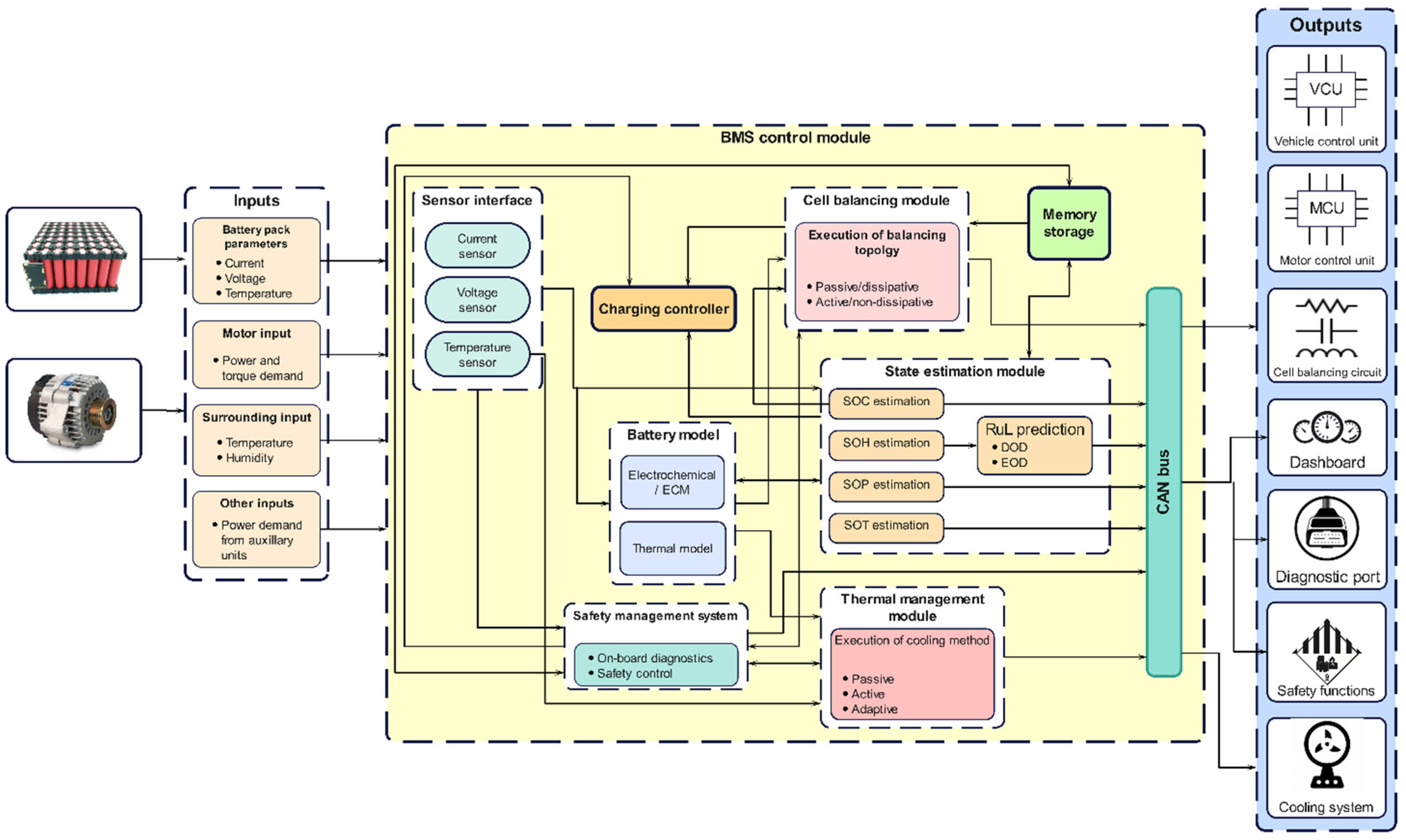
3. Internal Architecture of the Battery Management System in Electric Vehicles

The BMS is usually an embedded system and a purpose-built electronic regulator that performs the functions of monitoring, along with controlling certain quantities, such as current, voltage, and the temperature of batteries, thus maintaining battery cells within a safe operating region [29]. A general framework of a BMS used in electric vehicles is shown in Figure 5. From the architectural representation, the data flow in BMS can be represented in the form of input, data processing and output signals.

3.1. Inputs to BMS

The most essential input quantities are the battery pack current, voltage, and temperature. These inputs serve as the basis for monitoring the battery behavior and maintaining its operation within safe limits. Moreover, the power demand of the motor based on the input received from the throttle system, and the power demands of auxiliary units present in the EV, serve as other inputs to the BMS. The BMS supplies energy to drive the EV according to the motor’s power and torque requirement.

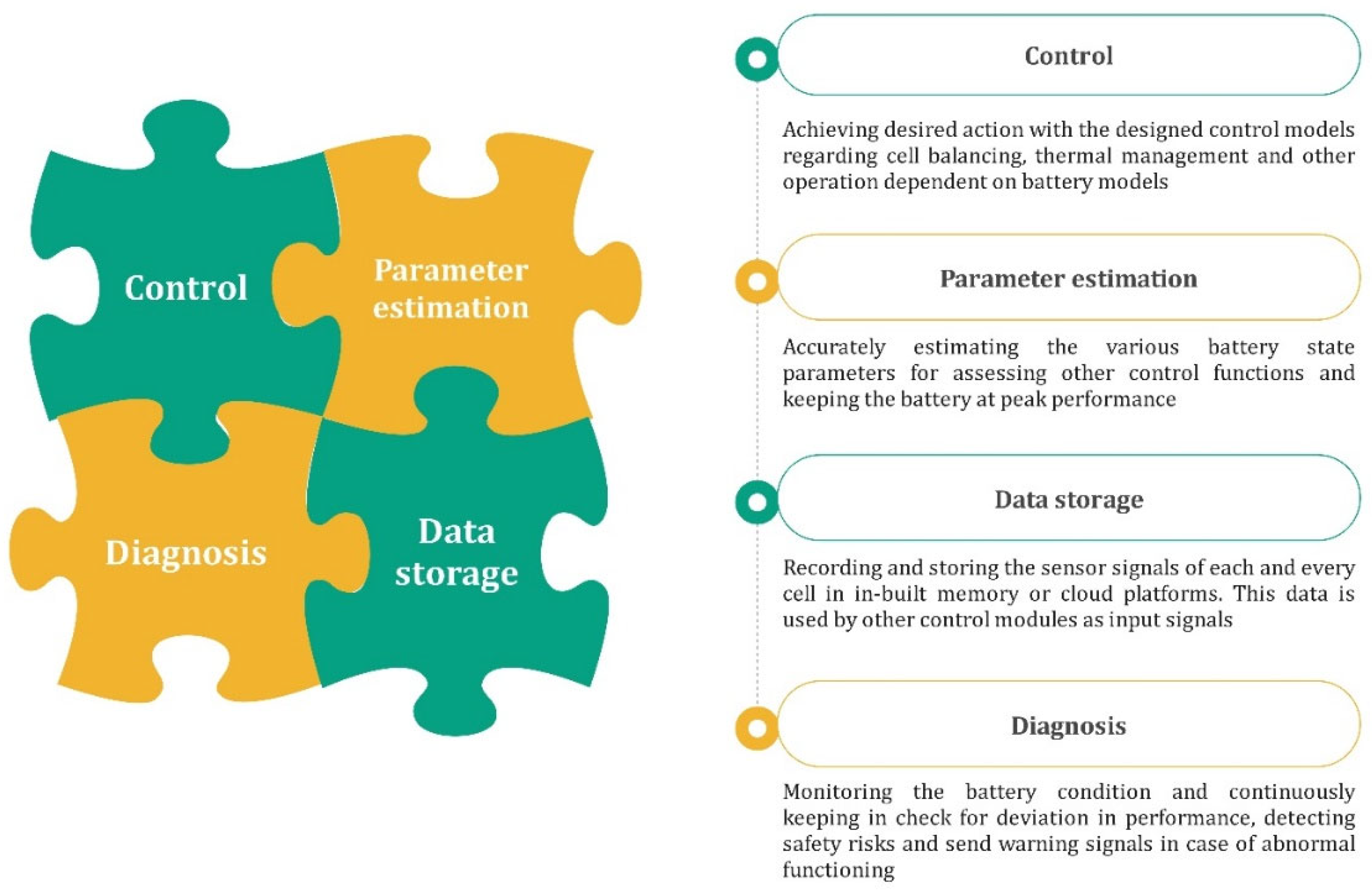
3.2. Control Module in BMS

The entire BMS is formed by combining multiple modules and establishing a communication route among these modules. The major modules necessary to realize the BMS are battery modeling, state estimation, cell-balancing, and thermal management. The communication between them is established using a controller area network (CAN) bus. The on-board current sensor and voltage sensor detect the current and voltage of the battery directly, and the surface temperature of the battery pack or cells is detected by temperature sensors. The BMS contains various battery models including an electrochemical model (ECM) and a thermal model. Battery models are essential for accurate prediction and optimization of different parameters, such as current, voltage, and temperature values obtained from the measured sensors which are crucial for estimating relevant battery states, such as SOC, SOH, SOP, and the remaining useful life (RUL) [30,31]. The SOC and corrected input voltage from the battery model are utilized by the cell-balancing module which aims to attain a uniform voltage distribution among the battery cells. The BTMS then acquires temperature-related input from the battery pack, battery models, SOT and surroundings, based on which it executes an appropriate cooling strategy to keep the temperature of the battery pack within safe limits [32]. A safety management module (SMM) and charging controller are also essential to ensure the safe operation of battery. The function of the charging controller is to receive inputs from different modules and to charge/discharge the battery at an optimized rate. For instance, depending on the SOC level of the battery, the controller will regulate the charge/discharge rate. The SMM includes on-board diagnostics and safety controls for the entire battery pack. Its function is to detect the failure of any module inside the BMS and to execute a suitable safety mechanism to preclude harsh consequences from occurring. It constantly communicates with other modules to diagnose faults related to battery overheating, overcharging, over-discharge, thermal runaway, communication errors, abrupt temperature rise, insulation faults, etc., and executes required safety mechanisms to bring the operating voltage and temperature back within safe operating limits [16].

3.3. Outputs from BMS

Control outputs sent by different modules inside the BMS are used to achieve several functions for managing the battery pack. To achieve a uniform SOC/voltage level between cells, a controller in the cell-balancing module operates balancing circuitry according to the magnitude of the voltage/SOC difference. The BTMS will execute an appropriate cooling or heating strategy to maintain the temperature of the battery pack within safe limits. The SMM first performs on-board diagnostics for detecting faults inside the battery pack. Faults detected are communicated to the user through a diagnostic port in the form of diagnostic trouble codes (DTC). Similarly, the major issues associated with battery temperature and voltage are sent to a dashboard to make the user aware of the situation. Then, the SMM activates several cell-level and pack-level controls to mitigate the fault and bring the battery temperature and voltage back within safe working limits. Meanwhile, the BMS maintains constant communication with other control units, such as the motor control unit (MCU) and vehicle control unit (VCU), to meet the power demand of the motor and other auxiliary electronic subsystems. The acquired input data is first utilized by the battery models in predicting the parameters, based on several models, which are later utilized by different internal modules for respective control actions.

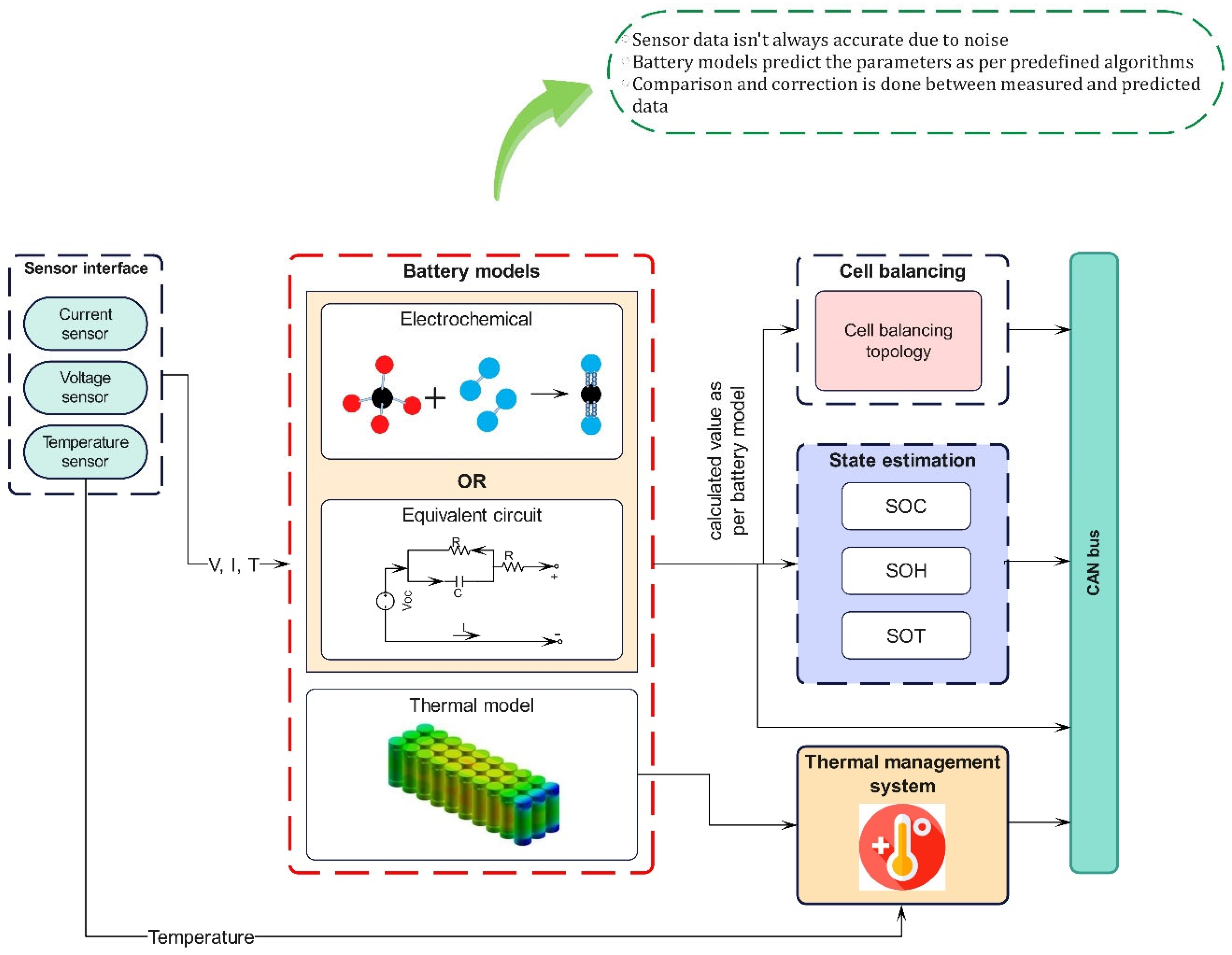
4. Battery Modeling in Electric Vehicles

For a safer and more efficient battery operation, accurate prediction of the battery behavior is required. The acquired input quantities, such as current, voltage, and temperature, contain noise in real-time scenarios because of varying operating conditions. Hence, when the directly measured values are used for state estimation, inaccurate results are produced. Therefore, accurate prediction of current, voltage, and temperature is required [33]. This role is fulfilled by the battery model which acts as a major source of data to the state estimations and other modules. These models are embedded with mathematical equations which calculate certain information based on the inputs received from the different battery sensors. Over the years, different battery models have been researched and classified into equivalent circuit models (ECM), electrochemical models and thermal models which are discussed in subsequent sections. However, there is a major difference between them from the point of their model development methodologies which play a detrimental role in the battery management application. The electrochemical models use physical laws that govern the internal electrochemical processes of the battery, whereas ECMs use a combination of resistors, capacitors, voltage sources, etc., to mimic the battery behavior [34]. Whatever the approach, the battery model must prove itself in terms of its accuracy, configuration effort required, computational complexity and interpretation ability. Figure 6 depicts the architecture schematic of battery models in the BMS.

4.1. Control Module in BMS

In this model, the electrochemical processes that occur in the batteries are represented by utilizing a set of coupled non-linear partial differential equations (PDE). They provide full information on the internal electrochemical dynamics, thermodynamic and kinetic phenomena occurring in the cell [35]. The typical representatives of the electrochemical model are the Shepherd, Nernst, Unnewehr universal and combined models. The Shepherd model describes the battery electrochemical behavior in terms of voltage and current, whereas the Unnewehr universal model is a simplification of the Shepherd model. It attempts to model the variation in the resistance to the SOC, whilst the Nernst model uses the exponential function to determine the SOC. The estimation of voltage using the Shepherd model follows experimental data closely and was found to be more precise than the Nernst model. This was verified since a higher estimated voltage error was observed when using the Nernst model. The combination models were found to be more accurate as they inherited the best features of all three models; however, the associated complexity often leads to an increased memory requirement and computational effort due to a large number of unknown parameters and may lead to reduced on-site accuracy when applied in the vehicle systems [36]. This can be countered by reducing the order of the model by discretization techniques to retain only the most significant dynamics of the full-order model. To overcome these complications, researchers have attempted to develop ECMs which use non-linear elements instead of PDEs.

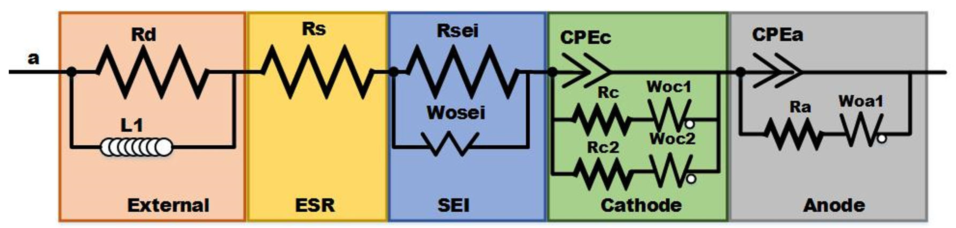
4.2. Equivalent Circuit Model (ECM)

The electrochemical model possesses a greater degree of complexity, which is further aggravated by parameter identification as analytical solutions do not exist for them [37]. Hence, ECMs are being adopted in more pragmatic situations, specifically in electric vehicles. They include the Rint model [38], Thevenin model [39], DP model [40] and the PNGV model [41]. ECMs use a combination of electric elements, such as inductors, capacitors, resistors, and, in some cases, Warburg impedance. The Rint model, the simplest form of ECM, contains internal ohmic resistance and an OCV source, the value of which depends on the SOC, SOH and the temperature of the lithium-ion batteries. Comparatively, it has the highest estimation errors as it does not account for the dynamic voltage performance. The Thevenin model is an extension of the Rint model having a parallel RC network in series to simulate the polarization effects. The DP model (also known as the second-order RC circuit), represents an improvement over the existing Thevenin model, and uses two parallel RC networks to describe the nonlinear polarization response of the LIB. The Thevenin and DP models have good estimation precision with small voltage errors [35]. The recently developed PNGV model has an added capacitor in series based on the Thevenin model [42]. Though the PNGV has higher accuracy in simulating the transient response process, as well as accounting for more complexities, The PNGV has higher accuracy in simulating the transient response process, as well as accounting for more complexities. Theoretically, the model should be analogous to the behavior of the battery in actual life but the existing equipment cannot detect the polarization process in detail making the capacitance determination impossible [43]. Therefore, the dual RC circuit or the DP model offers the best real-time performance and gives a more accurate SOC estimation compared to the other models [42]. As a result, the ECMs are preferred for battery modeling in EVs. On the basis of an equivalent circuit with elements and interconnections in lithium-ion batteries, the proposed design’s equivalent circuit is presented in Figure 7. Both the cathode and anode electrochemical reactions are represented by a series connection of interfacial capacitance and associated charge transfer resistance with Warburg impedance. An external inductive element, consisting of an inductor and resistor (L1 and R1) connected to the wiring between the electrodes and the measuring instruments, including the wounded current collector, is also included in the circuit. The cathode is shown as a model consisting of two distinct radiuses of active materials. The capacitance between the electrolyte and the electrical connection between particles must be placed in parallel with different pairs of series connections of diffusion elements and charge transfer resistance [44]. The only parameter left to be considered for modeling is the temperature distribution in the battery. The thermal models predict the heat generation and dissipation behavior within the battery according to which the thermal management system can function to achieve cooling.

4.3. Battery Thermal Modeling

It is essential to completely understand the heat generation characteristics and their dissipation in a Li-ion battery from a safety as well as an efficiency point of view. Controlling the temperature under the limiting values in all driving conditions is necessary. Hence, a thermal model is necessary which calculates and predicts the heat generation and dissipation rate of the battery pack. Among the various thermal models, a finite volume-based method is employed for transient thermal analysis and achieving real-time battery-pack cooling control [45]. The model effectively predicts the thermal behavior of the battery under various cooling conditions and duty cycles with a minimum temperature difference of nearly 3 °C between the actual and predicted values. Further, numerical modeling has proven to be valuable in studying the thermal behavior of the battery pack. Theoretically, calculating the heat generation and dissipation based on various heat transfer equations also gives lesser errors compared to the finite volume technique. It is also feasible considering the requirement of time and cost consumption with an accuracy of prediction within 1 °C [46]. In addition, a coupled electrochemical model is implied which evaluates the effect of the current and coolant flow rate on the battery temperature. The three-dimensional CFD-based electrochemical models are effective in reducing the requirements of different sensors and providing higher prediction accuracy [47]. A matter of concern in these numerical methods is that obtaining the values can be a tedious task for which a novel modeling method, called the Foster network model, has been devised. This method has also proven beneficial since the results obtained are comparable to CFD simulation, but they are obtained within minutes, unlike the time-consuming CFD calculations [48]. Apart from the conventional heat source, the study of thermal models enables learning about the ohmic and reversible heat generation occurring due to the internal chemical reaction in the battery. The battery modeling is an inevitable component of a BMS and, hence, constant efforts are put in to develop models with the latest technical approaches by harnessing the power of the large data generated.

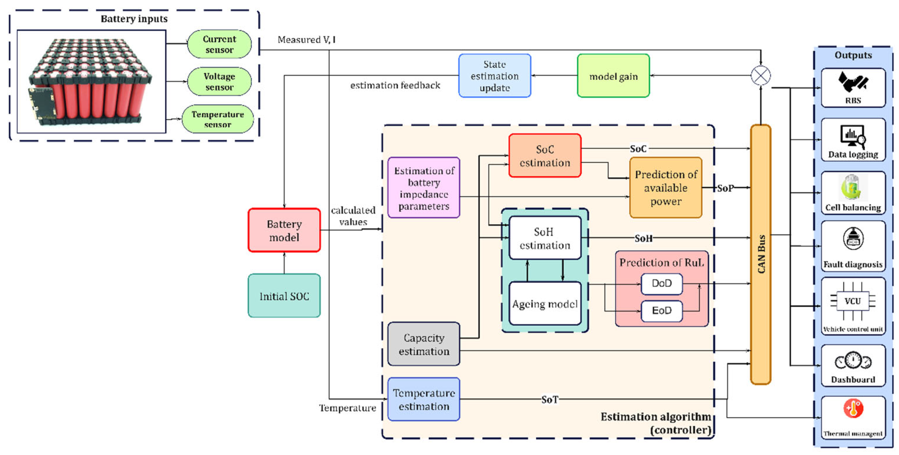
5. Battery State Estimation Methods

In BMS, battery state estimation is crucial by which the critical internal states are identified and monitored. Credible knowledge of the state of health (SOH), state of charge (SOC) and state of power (SOP) are necessary prerequisites for effective charging, and the thermal and health management of the battery. The schematic of the architecture presented in Figure 8 highlights the battery dynamics related to various state estimation parameters. This kind of model-based approach is widely adopted in EV applications.
In this approach, the accurate voltage, temperature and current values, predicted by battery models using advanced algorithms, are used as input. The main idea behind this method is to link the measured voltage, current and other variables with the battery states via predetermined complex mathematical equations [43]. By taking these parameters as the input to the model, a predicted value is obtained. The error between the predicted and the actual sampled value is calculated and further adjusted so that the estimated value of the state quantity follows the true value. Finally, the state values of SOC, SOH and SOP are obtained through various filters or observers. Then the respective estimated states are given as output to different systems and driver interfaces for communication. The different state estimation techniques are summarized and presented in the following sections.

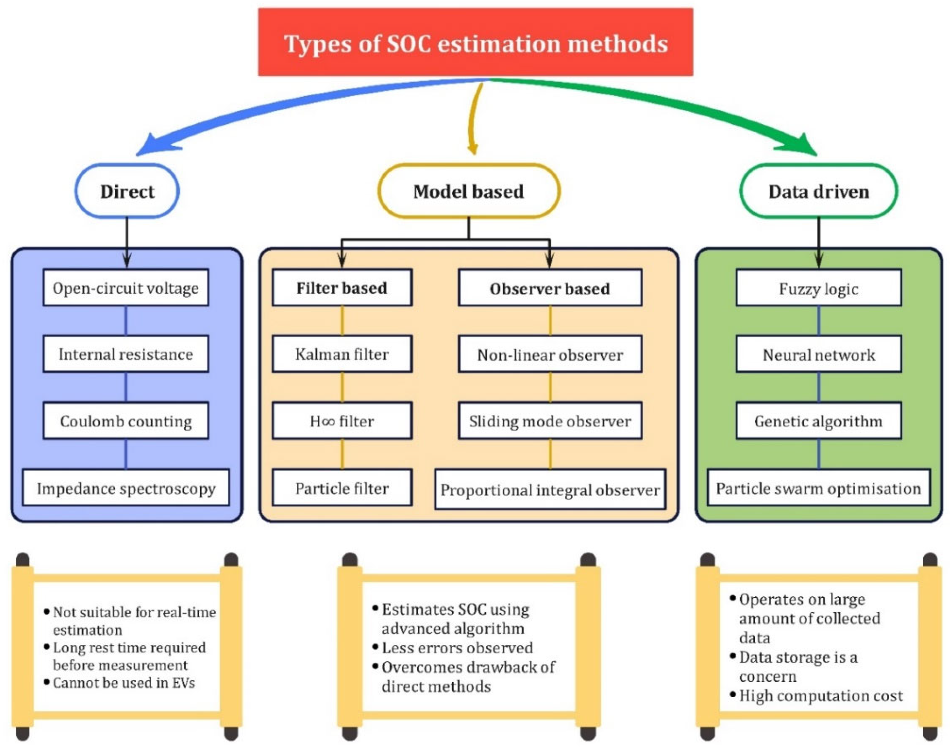
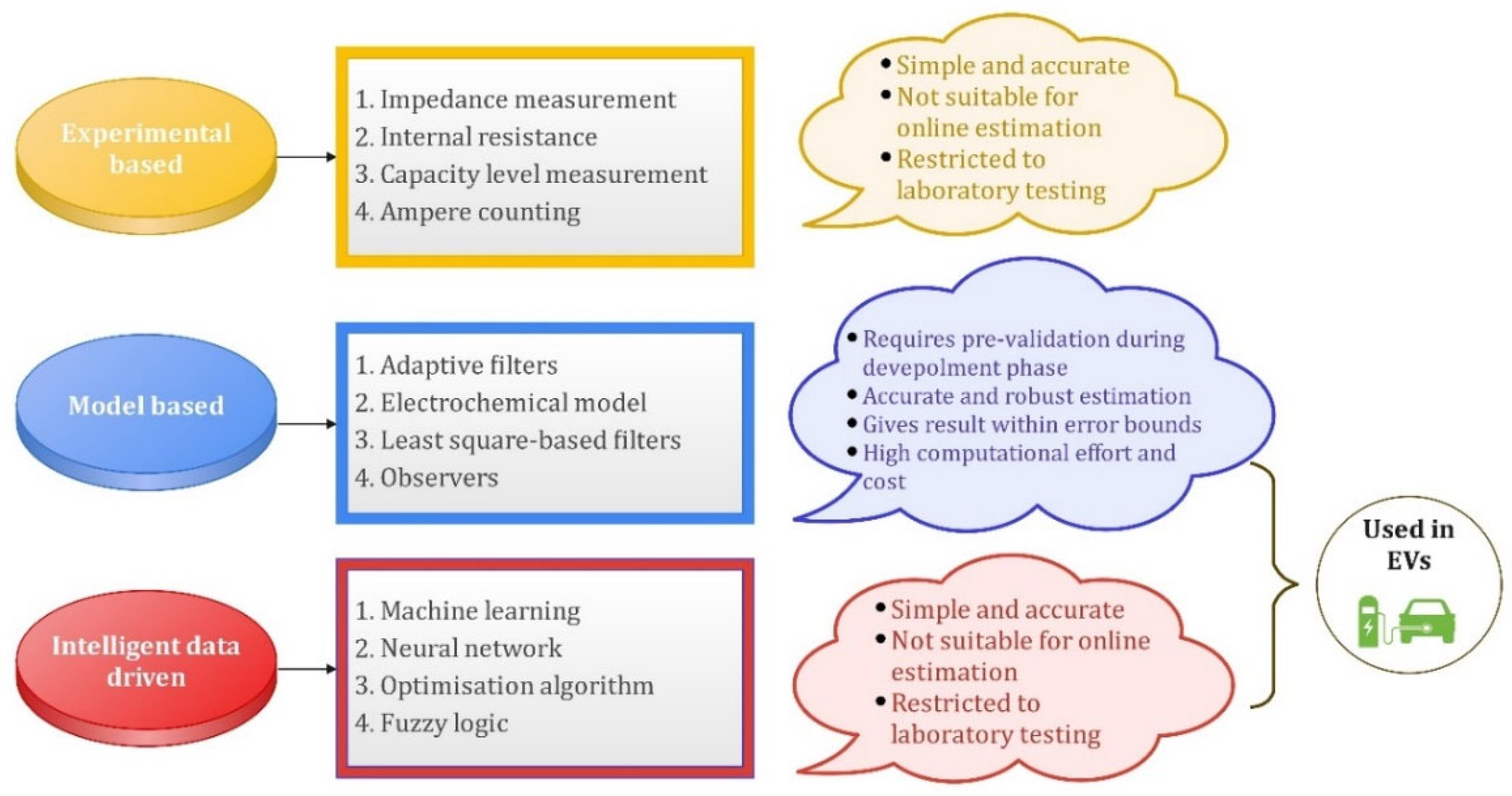
5.1. State of Charge Estimation Approaches

Among different states, the battery SOC indicates the available battery capacity and, hence, accurate estimation of the SOC is necessary for energy management in EVs [27]. The SOC of a cell is defined as the ratio of the current capacity of the cell to its nominal capacity. The nominal capacity is the maximum capacity of the battery given by the manufacturer. The equation for the estimation of SOC is given in Equation (4).
SOC = Q C Q N   %  
where QC is the current capacity and QN is the nominal capacity. The numerous techniques employed in SOC estimation can be categorized as either direct, model-based or data-driven. The prominent techniques adopted by researchers for SOC estimation are presented in Figure 9 and their outcomes and results are covered in Table 1. The direct methods, such as open-circuit voltage, internal resistance, Coulomb counting, etc., are accurate, but they are not suitable for adaptation in real-time due to the requirement of longer rest times before measuring or sensor errors inclusion. Hence, these methods are not being implied in EVs [49]. Instead, certain filter-based methods, such as the Kalman filter (KF), particle filter (PF), and H∞ filter, placed under the model-based category, are used in SOC estimation. These methods are capable of restricting the effects of uncertainty and perturbation leading to minimal errors as low as 2% in the estimated SOC [50]. The KF algorithm has a significant value in EVs as it overcomes the shortcoming of current integration dependence on the initial value and does not even require large sample data [51]. The model-based category also encompasses some non-linear, observer-based methods that provide a fast convergence rate and high estimation accuracy [27,52]. However, the Kalman and particle-based filter methods show less errors in estimation, e.g., the filter-based methods give a maximum error in the range of 0.1–2%, whereas the observer-based methods range around 2–3% [52]. Finally, the data-driven methods presume the Li-ion battery as a black-box model and learn the internal dynamics using different measured data. Well-known examples include fuzzy logic, neural network and genetic algorithm, which also present more errors in estimation (ranging between 3–6%) when compared with filter-based methods [52]. However, in data-driven-based deep learning, pre-training the model can be performed with a massive amount of data to improve the calculation speed and prediction accuracy [53]. This has proved to be a promising method if the data handling and storage issues are tackled properly. All the SOC estimation methods play a significant role, since they influence the battery SOH in the long term, which is further discussed below.

5.2. State of Health Estimation Approaches

To ensure safety and avoid potential battery failures, proper evaluation of SOH is of paramount importance. SOH is defined as the ratio of discharge capacity to the rated capacity of the battery. SOH estimation is given in Equation (5).
SOH = Q N O W Q N E W × 100  
where QNOW is the discharge capacity and QNEW is the rated capacity of the battery. Observing the different studies conducted, the SOH estimation methods can be classified as experimental and model-based methods which are mentioned in Figure 10. Methods such as internal impedance, resistance and capacity level measurements are mainly laboratory-based methods and are not suitable for real-time operating conditions [62]. However, certain model-based methods, including Kalman and related filters [63], and even observer-based methods, are some of the approaches used in EVs. The adaptive observer model estimates the series resistance value which is used to evaluate the SOH of batteries with a fast convergent rate to ensure less error [64]. But this method is based on certain assumptions, such as full cycling with a constant current which cannot be applied in real-time EV batteries. Hence, a more practical application method using neural networks eliminates the dependence on such assumptions and can be used in dynamic scenarios [65]. A similar approach based on a multilayer perception (MLP) scheme is presented which gives errors <1% when a trained model is implemented and the ANN utilizes the actual driving pattern rather than standardized experimental data. Since SOC and SOH are closely related in ways that the charge distribution affects the battery health, the estimation methods are also quite similar. The intelligent data-driven methods that includes optimization algorithms, machine learning methods [20] and self-learning neural networks help in estimating SOH with high precision [66]. For efficient prognostic and health management of the battery, the depth of discharge (DOD) and end of discharge (EOD) time are crucial quantities alongside other states. A battery’s depth of discharge (DoD) indicates the percentage of the battery that has been discharged relative to the overall capacity of the battery. Hence the DoD plays a critical role in determining the battery cycles and ageing in the longer run. Similarly, the EOD time of the battery is the time at which the battery voltage or SOC reach some threshold values, after which the battery needs to be recharged. Hence, accurate prediction of EOD time is also essential in enhancing battery life. Methods such as model predictive, particle filter (PF)-based estimation methods, and recursive least square, are used in DoD estimation. Similarly, the EOD time can be predicted using several ageing models and algorithms, such as the linear regression model [67], particle filtering (PF) with radial basis function neural network (RBF-PF) [68], Bayesian hierarchical model (BHM) [69], electrochemistry-based ageing model [70], PF with outer feedback correction loops (PF-OFCLs) and unscented Kalman filter with outer feedback correction loops (UKF-OFCLs) [71]. The review of SOH estimation methods is tabulated in Table 2. With the battery health kept in check, it is necessary to estimate the future power availability which is taken care of by the SOP estimation.

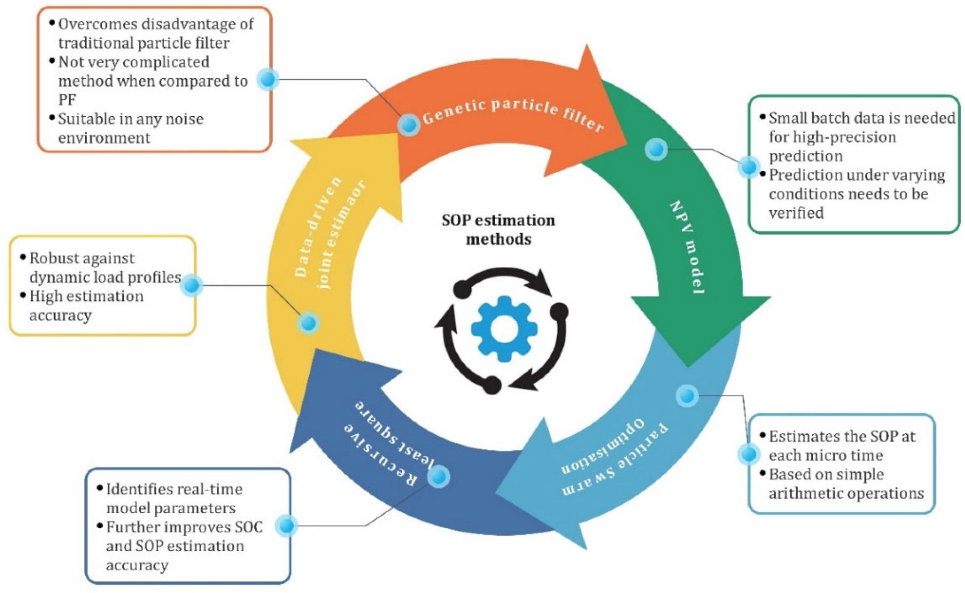
5.3. State of Power Estimation Approaches

The SOP evaluates the maximum charge and discharge capabilities and can be used to estimate power requirements between the battery system and other power sources. Among the many methods, the improved genetic particle filter method overcomes the disadvantage of simple particle-filter-based methods which lack diversity of particles [79]. The NPV model is a simple structured model that uses little primary data for high precision results [80]. This makes the structure simpler and model parameters can be more easily identified. Further, to tackle the issue of highly complex control, a novel strategy based on extremum-seeking theory ensures good convergence and is simple to implement [81]. Another strategy involves multi-time-scale observer-based estimation wherein particle swarm optimization (PSO) is applied to identify the battery parameters while the unscented Kalman filter (UKF) is used to estimate the battery SOP at each micro time [82]. A major advantage of this approach is that this method is simple and can be implemented on a microcontroller. Multiple methods are used either solely or in combination for the efficient estimation of SOP. This is necessary to meet the objective of achieving accurate state estimation with minimum error. The different SOP estimation control techniques are summarized and presented in Table 3 and their schematic representation is captured in Figure 11. Such estimated battery states are crucial in determining the charging–discharging characteristics which are essential for balancing voltage levels among individual cells.

6. Battery Cell-Balancing

The SOC of each cell is crucial in determining whether an imbalance in the battery string exists or not. A cell imbalance occurs if there exists any difference between the SOC or voltage of the cells. This in turn adversely affects the aging characteristics of the battery and lowers its efficiency [87]. The imbalance is imposed by either manufacturing errors or non-uniform temperature distribution among the cells [15]. Overcharging and over-discharging are two common negative effects of voltage imbalance in batteries. Overcharging, particularly in Li-ion batteries, lowers the lifetime, decomposes battery electrolytes, compromises battery safety and initiates dendrite formation. Moreover, deep discharging leads to oxidization of copper electrodes [16] which may lead to battery explosion or fires in some cases [87]. These undesirable events demand the implementation of cell-balancing strategies to protect the battery pack against potential harm and thus increase its lifetime [88,89]. For a dynamic application, such as ESS in EVs, where reliability and safety are of the utmost importance, maintaining the voltage of cells at the same level becomes a prerequisite for the efficient operation of EVs. The function of the cell-balancing module in a BMS in an EV is to avoid overcharging and deep discharging of battery cells by maintaining an equal charge in all the cells of the battery. Several investigations have been performed in the domain of cell-voltage-balancing in EVs and several methods have been proposed to date. The generalized architecture of the cell-balancing module in the BMS is schematically presented in Figure 12.

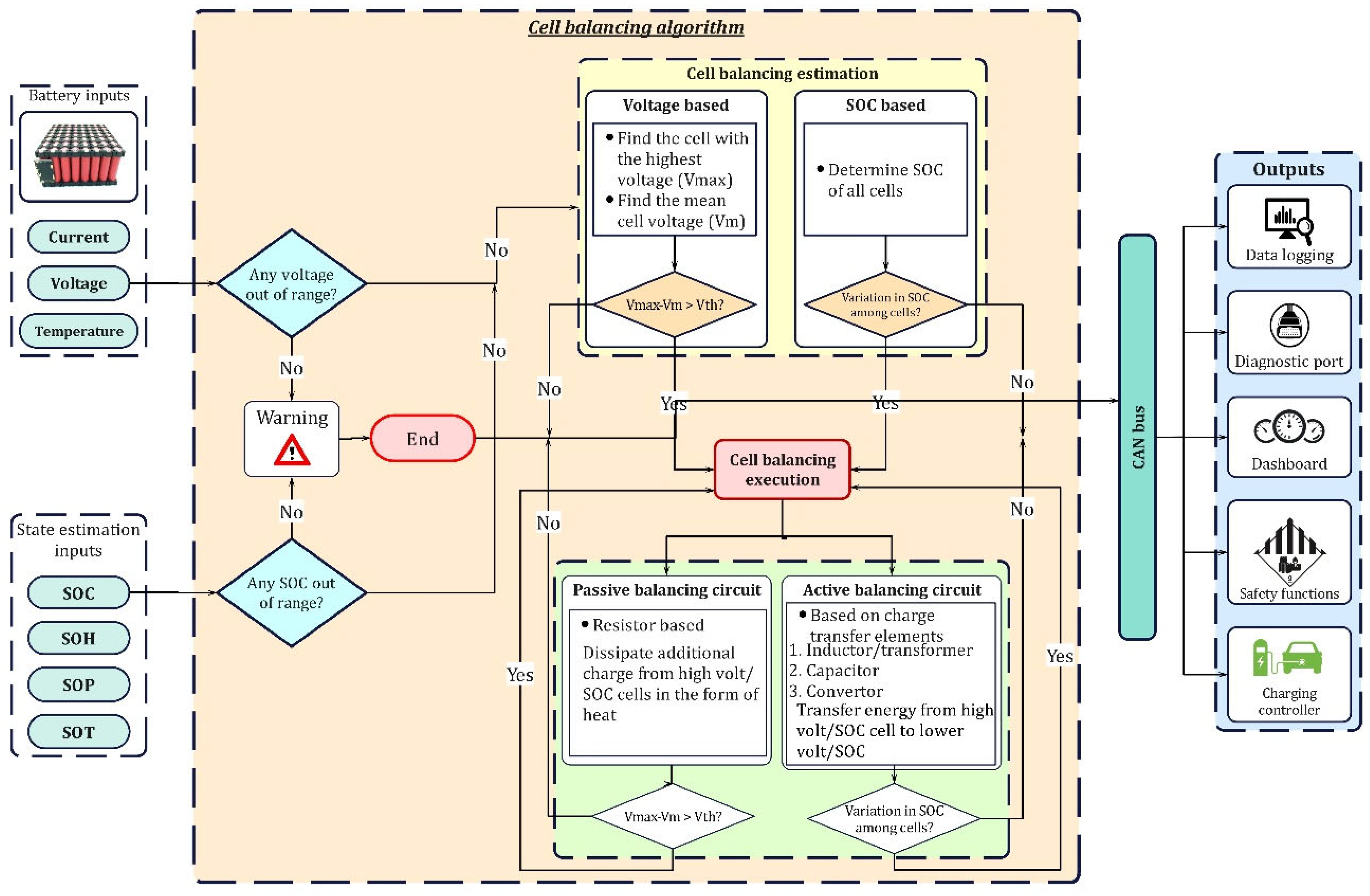
6.1. Cell-Balancing Architecture along with Workflow

From the state estimation module and battery pack, the SOC and voltage of all cells are taken as inputs. Different algorithms, such as voltage-based or SOC-based, are employed for the estimation approach. These estimation approaches are detailed in Section 6.2. If there is a requirement to balance cells, then a suitable balancing topology, either passive or active is implemented. These topologies are expounded in the subsequent sections. Once the balancing cycle is accomplished, the control algorithm will again check for the need for balancing. The controller will end the process if balancing is achieved, or else the same procedure is repeated until all the cells are balanced. The cell-balancing module is in constant communication with other modules also inside the BMS, such as the charging controller and the safety management system. In the event of danger, the safety management module executes suitable safety functions to avoid severe causalities and communicates the fault to the user via a diagnostic port and on the dashboard. To ensure the voltage-balance among cells, several topologies have been proposed which are discussed in the following sections.

6.2. Classification of Cell-Balancing Topologies

From the cell-balancing architecture, based on the input parameters, estimation of the requirement for cell-balancing can be performed, either based on cell voltage or the SOC of individual cells [90]. Generally, topologies for balancing cell voltages in EVs fall into passive and active cell-balancing categories. In passive balancing, an additional charge from the high-voltage/SOC cell is dissipated into heat via resistors [91], whereas, the charge from the higher voltage/SOC cell is transferred to lower voltage/SOC cell(s) in active balancing. The passive topologies are simple and easy to implement but offer less balancing accuracy and involve a higher balancing time [92]. The active balancing topologies can be classified based on charge transfer elements [93,94] which use inductors/transformers, capacitors, and converters as charge-transferring elements. When compared to passive techniques, active methods are more accurate and render faster balancing; however, circuit complexity and the associated cost are major downsides of active topologies. The existing passive and active balancing topologies are critically reviewed in subsequent sections.

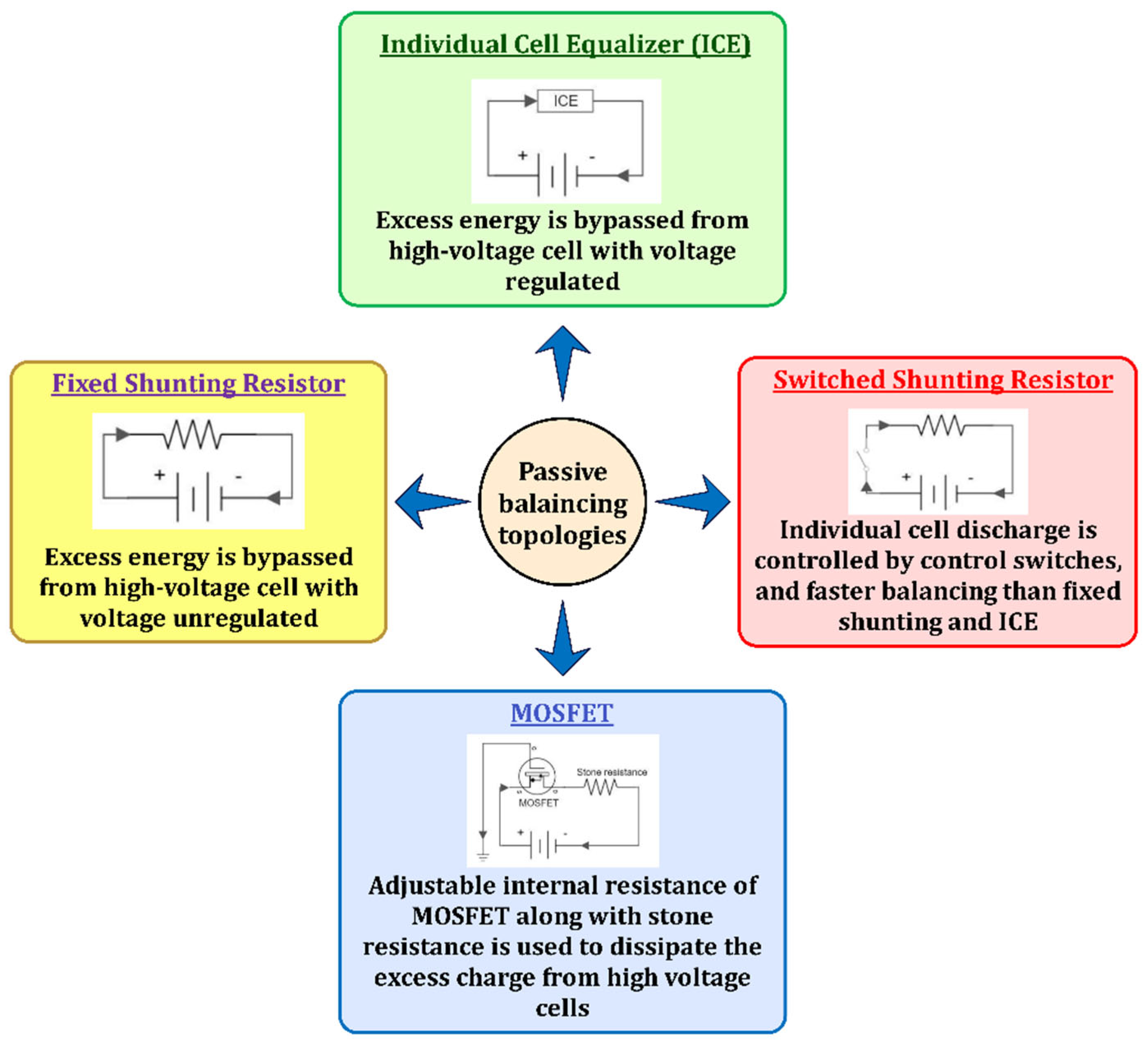
6.3. Passive Balancing Topologies

Passive balancing topologies remove the excess energy from higher voltage/SOC cells in the form of heat, via resistors or other heat-dissipating elements. These methods are simple to control, least costly, and small; nevertheless, loss of excess charge requires efficient thermal management for controlling the overheating of cells/modules. Applications of fixed shunting resistors [95] are limited to lead-acid and nickel-based batteries as they can be overcharged, while Li-ion batteries cannot be overcharged. On the other hand, switched shunting resistors [96] can be used in Li-ion batteries. Moreover, they can attain faster balancing than fixed-shunting resistors and ICE. ICE bypasses the current from high-voltage cells and solves the issue of drawing regulated current into shunt elements, and, thus, minimizes the energy losses present in shunting resistor topologies [97]. Dissipating energy using MOSFET [98,99] is performed only at the end of the charging process; hence, energy losses are less than with the shunting resistor topology but the balancing time is still higher. In addition, these topologies are suitable only in the charging phase; they are not helpful when cells are being discharged, which is a serious drawback. Passive techniques can be used in HEV applications [100], whereas their implementation in EVs is infeasible because it could demand a costly design with a more effective thermal management system due to high energy losses. To overcome such issues, active cell-balancing topologies are developed. The existing passive cell-balancing approaches are described in Figure 13.

6.4. Active Balancing Topologies

Passive topologies are inefficient owing to high energy losses occurring in heat-dissipating elements. Hence, active cell-balancing topologies are developed to tackle this issue. Based on the charge transfer element, active topologies that can be used in EVs use different elements, such as inductor/transformer, switched-capacitor and converter.

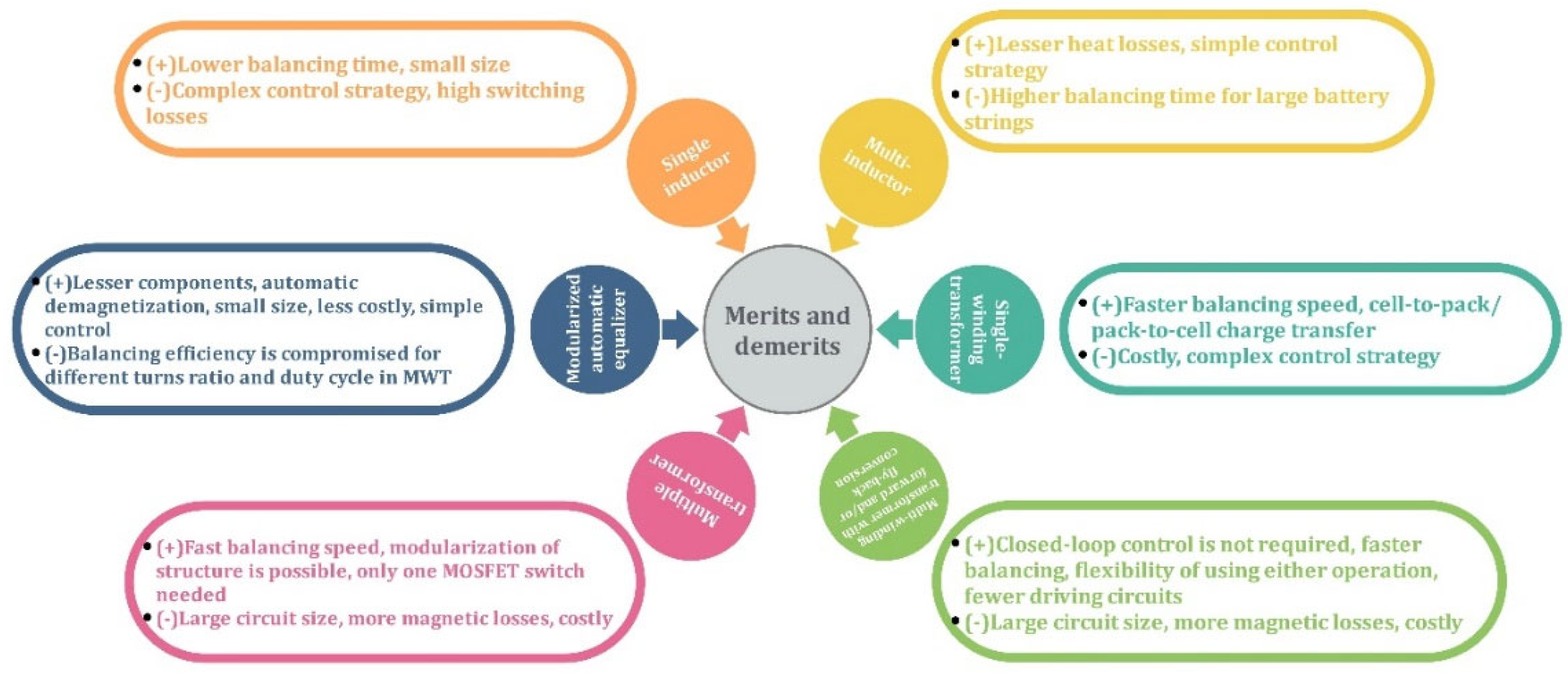
6.4.1. Inductor/Transformer-Based Topologies

In these topologies, energy from high-voltage cells to low-voltage cells is transferred by either inductors or transformers. Based on the number of inductors/transformers used in the balancing circuit, several configurations are proposed. Single inductor configuration use only one inductor to transfer energy from a high-voltage cell to the entire battery pack which reduces magnetic losses [101]. Multi-inductor topologies transfer energy between neighboring cells (cell-to-cell) due to which it takes more balancing time than a single-inductor typology which renders the system inefficient for applications using large battery strings, such as EVs [102,103]. Transformer-based balancers are classified into three main categories: single-winding, multi-winding, and multiple transformers [104]. The single-winding transformer uses a single winding on both primary and secondary sides to achieve cell-to-pack/pack-to-cell charge transfer [105]. It provides an optimized path for power transfer to minimize power losses. These cell-to-pack/pack-to-cell approaches have been proven effective for balancing cell voltages, but due to the presence of energy overlap and high-voltage stresses, the balancing efficiency is compromised. To overcome this hurdle, direct cell-to-cell topologies are introduced. In the multi-winding transformer (MWT) topology, single winding occurs on one side and multi-windings are given on the other side. The number of windings should be the same as the number of connected cells. MWT may adopt the forward and/or fly-back conversions to attain faster balancing [106,107]. The multiple-transformer topology transfers energy from the highest charged cell to the battery pack or vice-versa [108]. One concern with transformers is the losses occurring in their windings. To curtail these losses, separate demagnetizing circuits are used, which makes the system bulky and expensive. To overcome these issues, a modularized automatic equalizer (MAE) is used which achieves automatic demagnetization through complementary structures of secondary windings, thereby eliminating demagnetizing circuits [109,110]. It can transfer energy from any cell to any cell in the battery pack. The cell-to-pack/pack-to-cell and direct cell-to-cell architecture transfer charge at relatively higher efficiency than other architectures [87]. In comparing the aforesaid methods, the single-inductor has proven to be efficient due to lesser magnetic losses and remarkable balancing speed; however, its complex control, more sensing elements, need for a filter capacitor, and stresses acting on switches/MOSFETs, pose some difficulties when used in Li-ion batteries. Multiple transformers can provide faster balancing speed, better modularity than MWT, and can be easily used for long battery strings. Furthermore, MWTs can balance the cells only in the charging phase [111]. Moreover, retaining symmetry in the transformer’s structure becomes arduous when the number of windings exceeds a certain number and current stresses acting on primary side-switches in MWTs are high. Hence, multiple transformers are preferred over MWTs in EVs. On the other hand, the modularized structure uses a simple control scheme whilst maintaining all the benefits offered by other topologies and provides freedom to be used for long battery strings as well. Thus, it tends to outmatch other topologies which makes it well-suited for balancing Li-ion batteries in EVs. Despite faster balancing and high efficiency, intelligent control and high cost are huge challenges for inductor-based topologies. Therefore, a cost-efficient approach is required. Hence, switched-capacitors are an economical solution compared to inductors. The research studies on cell-balancing using inductors/transformers are summarized and presented in Table 4. Their respective merits and demerits are outlined in Figure 14.

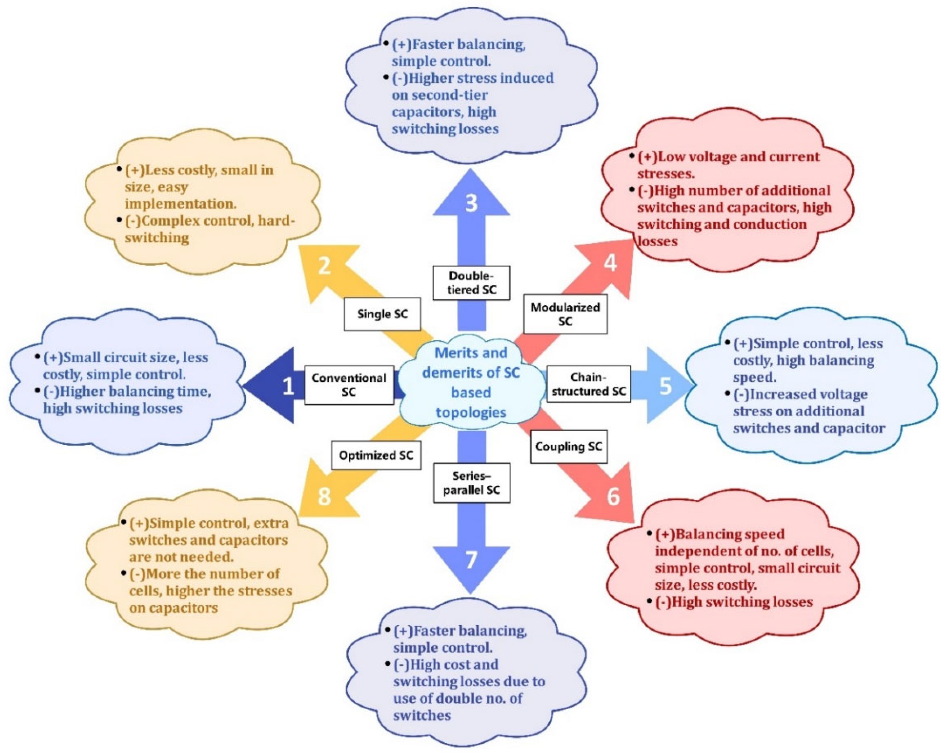
6.4.2. Switched Capacitor (SC)-Based Topologies

Numerous economical topologies based on the number of capacitors and switches have been developed. The conventional SC transfers charge among neighboring cells [112,113]. The single SC provides higher balancing speed since it transports energy from high-voltage cells to low-voltage cells directly [114]. The double-tiered SC (DTSC) uses additional rows to enable charge transfer between non-adjacent cells [115,116]. It attains faster balancing than the conventional SC. In modularized SCs, the battery uses a modular structure and switched-capacitor approach to achieve cell-to-cell and module-to-module balancing [117,118]. The modularity enhances balancing speed over conventional SCs. The chain-structured SC (CSSC) optimizes the balancing speed by connecting the first cell in the battery string with the last cell, thus reducing the distance between the two farthest cells by half. However, higher voltage stresses on capacitors and switches make them inappropriate for large battery strings [119]. The switched coupling capacitor gives flexibility for a modular structure along with faster balancing [120]. The energy loss is minimized in a series-parallel SC by maintaining constant charge throughout the balancing process; however, the use of more switches and capacitors per cell increases switching losses [121]. The optimized SC can achieve the same balancing speed as series-parallel SC and CSSC without using additional capacitors and switches [122]. Although the aforesaid topologies can maintain high balancing speed, high switching losses are a major downside. Therefore, resonant SCs, such as the quasi-resonant SC and the chain-structured resonant SC (CSRSC) have been developed to attain a zero voltage gap (ZVG) between cells and zero current switching (ZCS) [123,124]. Resonant SCs achieve a reduction in switching losses through ZCS whilst enhancing the balancing speed. Comparing the topologies, switching losses and large balancing time make the conventional SC the least efficient. The DTSC, modularized SC, CSSC, coupling SC, and series-parallel SC, attain faster balancing than the conventional SC. The DTSC balancing speed drops when the number of cells in series increases. Moreover, they tend to cause a higher balancing time than inductors and transformers, making them less efficient in terms of balancing speed. Despite the shortcomings, the SCs referred to have several merits that outweigh their demerits, such as low current stresses acting on MOSFETs, lesser controller complexity, fewer sensing elements, and, above all, the ability to effectively balance the cells during both charging and discharging phases, unlike some inductor and transformer-based topologies. The ability of the optimized SC to achieve balancing as rapidly as series-parallel SCs and CSSCs, without having to use extra switches and capacitors, strengthens its overall balancing efficiency. The resonant SCs ensure lesser switching losses and faster balancing speed making them a highly efficient SC approach that can be used for cell-balancing in EVs. The existing literature indicates that resonant and modularized configurations have become a strong focus of research and are showing rapid development. Moreover, the recently developed star-structured LC resonant switched capacitor and the switched capacitor with modularized chain structure showed efficiencies of 98.7% [125] and 98.8% [126], respectively. However, further investigation for reducing the balancing speed of SCs is still required to ensure efficient performance in EVs. Nowadays, different converters are used for mitigating the issue of poor balancing speed. The major outcomes derived from research on SCs are encapsulated in Table 5. The merits and demerits pertaining to SC-based topologies are demonstrated in Figure 15.

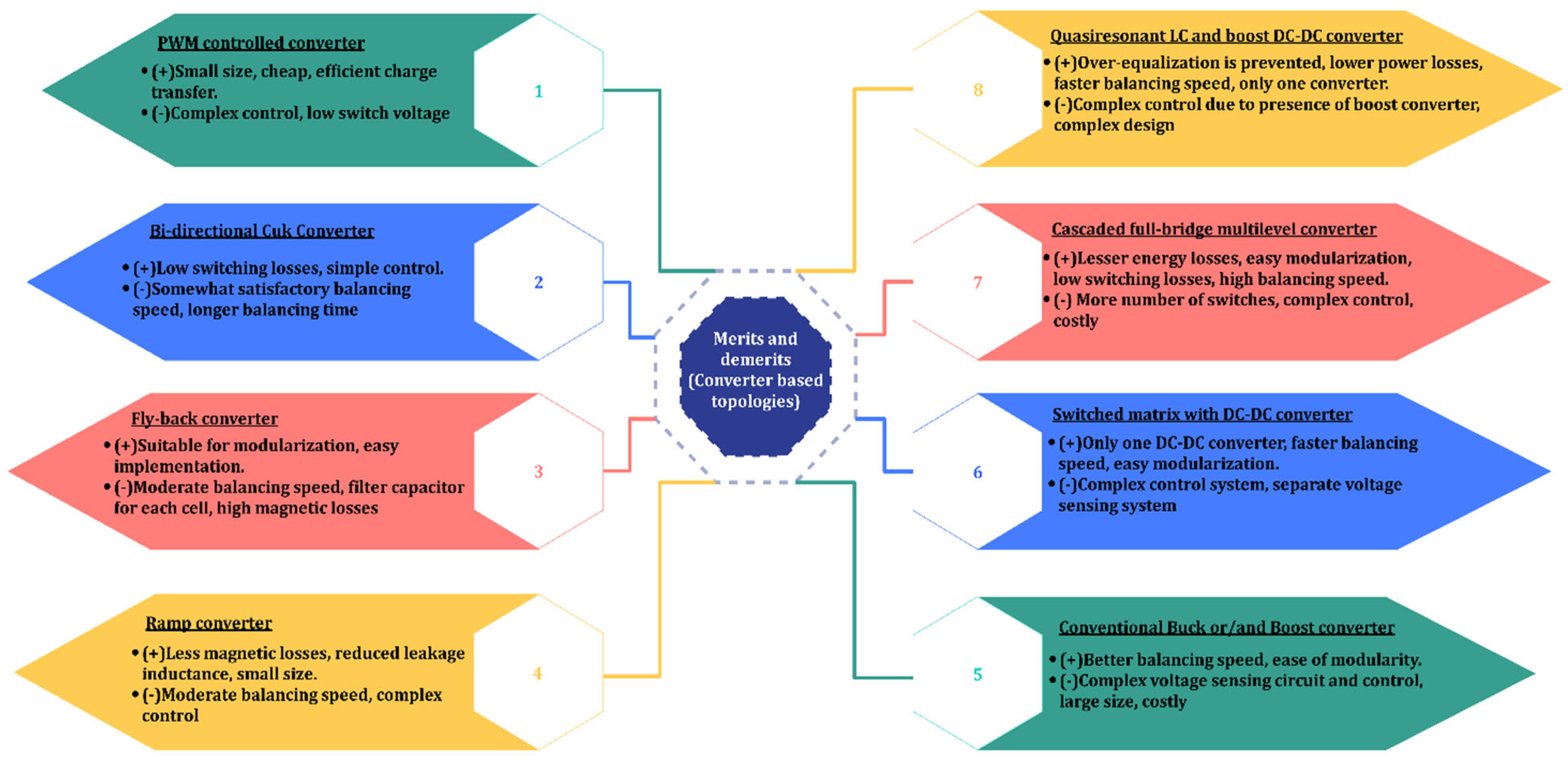
6.4.3. Converter-Based Topologies

Power converters are widely used to transfer charge between high-voltage and low-voltage cells in EV batteries. Nevertheless, one major drawback is their associated cost and complexity in design and implementation. The conventional PWM-controlled converter utilizes a pulse-width modulation (PWM) signal that operates switches to transfer charge among neighboring cells [127]. Their charge transfer efficiency is higher; nonetheless, they involve a higher balancing time and require complex control. The Ćuk converter [128,129] also works on the principle of PWM for transferring charge from one cell to another. It can be viewed as an upgrade of the conventional PWM-controlled converter since it gives lower voltage or current stresses on switches than in the conventional configuration. However, it uses a capacitor to store energy and supply it to low-charge cells, unlike the conventional PWM-controlled converter [130]. It is more efficient than a conventional buck-converter because of its ability to provide ripple-free input current naturally [131,132]; the buck-converter has to use one extra inductor for providing ripple-free current which compromises its efficiency due to additional core and copper losses, size, cost, and weight. The fly-back converter achieves cell-to-pack balancing during the charging phase to avoid overcharging of cells, while it achieves pack-to-cell-balancing during the discharging phase to preclude over-discharging [133,134]. Here, periodic charging/discharging of cells enhances the charge distribution efficiency. Moreover, its suitability for modularization makes it more favorable for EV applications. Switching losses can be reduced by using the PWM signal to control the balancing circuit [135]. The Ramp converter uses a single secondary winding for two neighboring cells; as a result, magnetic losses and circuit size are reduced considerably over MWTs—nonetheless, its design is complicated [136]. Buck and boost converters are used to step down and raise the DC voltage, respectively [137]. They provide enhanced performance in terms of balancing speed and modularization over Ramp and Ćuk converters. The selective balancing of cells, irrespective of their positions, enables direct energy transfer to least-charged cells using a switched-matrix with a DC-DC converter [138]. It offers faster balancing speed than other converters and SCs and ease of modularization. However, it experiences high-voltage stresses when the battery string length increases. The full-bridge converter has a higher charge-transfer efficiency than many converters since it can charge/discharge cells at different currents according to their needs [139]. This ability minimizes the energy losses that would occur otherwise. Moreover, the use of a full-bridge configuration enhances the balancing speed, making it well-suited to EV application. It is used in EVs as a DC-DC converter and in plug-in HEVs for AC-DC conversion and balancing [140]. QRLCC-BDDC exploits the benefits of a quasi-resonant LC converter and boost DC-DC converter [141]. QRLCC transports energy with ZCS and BDDC regulates balancing currents according to the voltage difference. This method solves the issue of obtaining ZVG between the cells due to a voltage drop across power devices existing in current direct-cell-to-cell topologies. When compared with other direct-cell-to-cell topologies, this topology affords higher balancing current, reduced circuit size, cost, and weight, along with the added benefits of ZVG and ZCS. Thus, QRLCC-BDDC converters show high potential for being used in long battery strings in EVs. From the discussion provided in this section, it can be seen that most of the converters achieve the benefit of easy modularization at the expense of complex control strategies and high cost. Hence, it becomes vital to maintain a balance between the proposed merits and demerits depending upon the application to ensure an efficient converter. Currently, resonant, buck or/and boost, fly-back converters and other modularized configurations are employed commercially for battery cell-balancing in EVs [140]. The salient outcomes of research studies related to different converter-based topologies are summarized and presented in Table 6. The merits and demerits of converter configurations are given in Figure 16.

7. Battery Thermal Management System

Lithium-ion batteries, like any other batteries, run by converting the chemical energy into electrical energy and vice versa. This conversion involves heat generation. The total heat generation is given by the Equation (6), as follows:
Q = I × ( V ocv V c V ocv T )
where I is the current (Am−2), Vocv is the open circuit voltage, Vc is the cell voltage at each time interval during discharge, and T is the temperature (K or °C). It consists of two types of term: irreversible I × (Vocv − Vc) and reversible I × (T ∂Vocv/∂T) [142]. Changes in entropy during the chemical reactions generate reversible heat, while the irreversible heat is a result of internal resistance that consists of concentration, activation and ohmic polarizations. As the heat generation inside a battery changes dynamically during its operation, the accurate measurement of heat generation is very challenging, as the heat source terms are a function of the temperature changes [143]. In addition, failure of the cell-balancing module in bringing the overcharged cells down to a mean voltage level can cause overheating in some region of the battery pack. Due to such factors, the battery pack deviates from its normal operating temperature range and starts operating at abnormal temperature levels outside of its safe limits. This leads to non-uniform temperature distribution inside the battery pack. This non-uniform temperature distribution, if not controlled, can cause battery degradation, thermal runaway, and even catastrophic failures [144,145]. To address these issues, the operating temperature of the battery pack should be in the range 15–35 °C [146]. Hence, it is essential to have a thermal management system which can ensure the battery temperature is within safe limits. Figure 17 highlights the requirements and functions of an efficient BTMS in EVs.

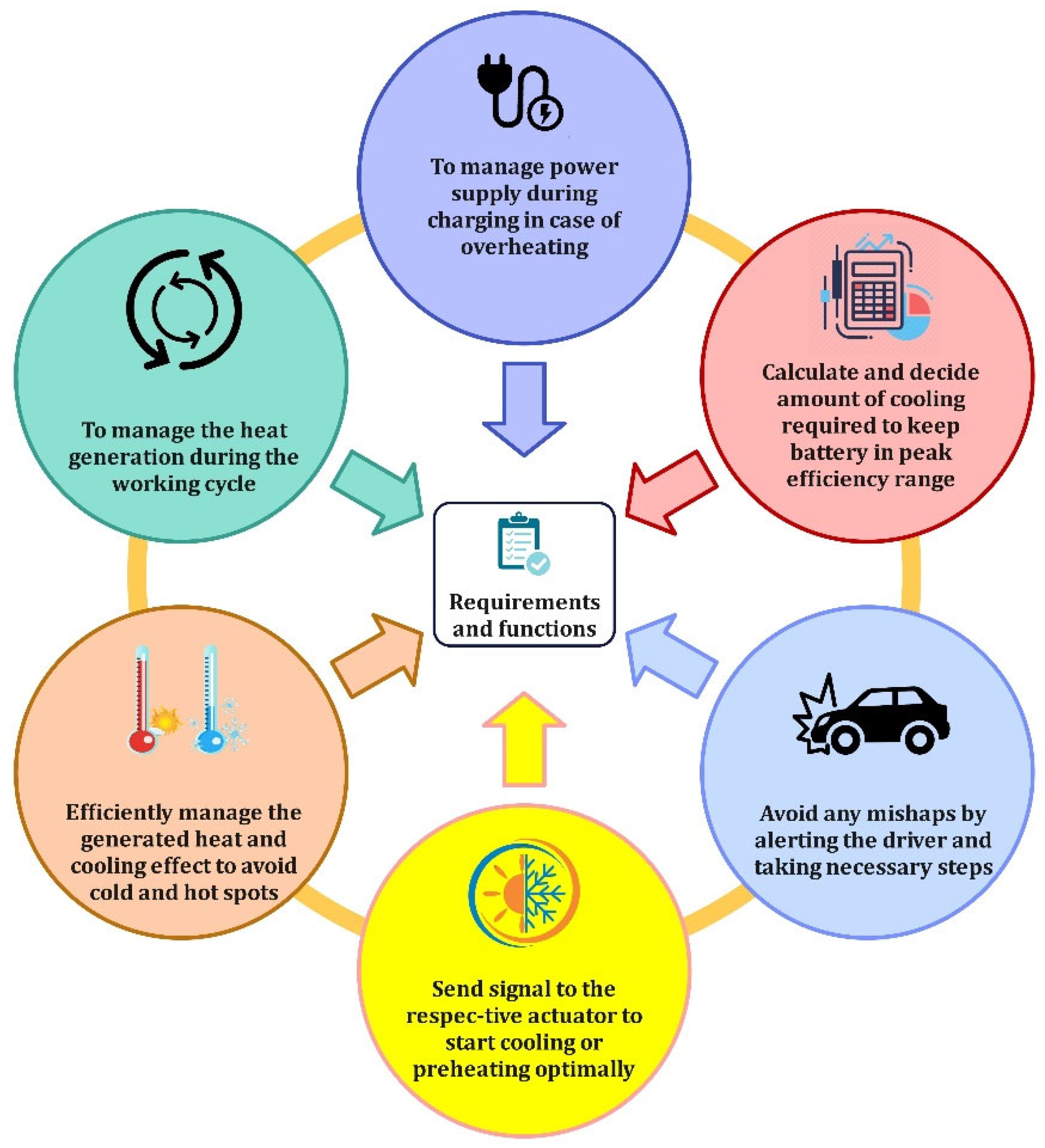
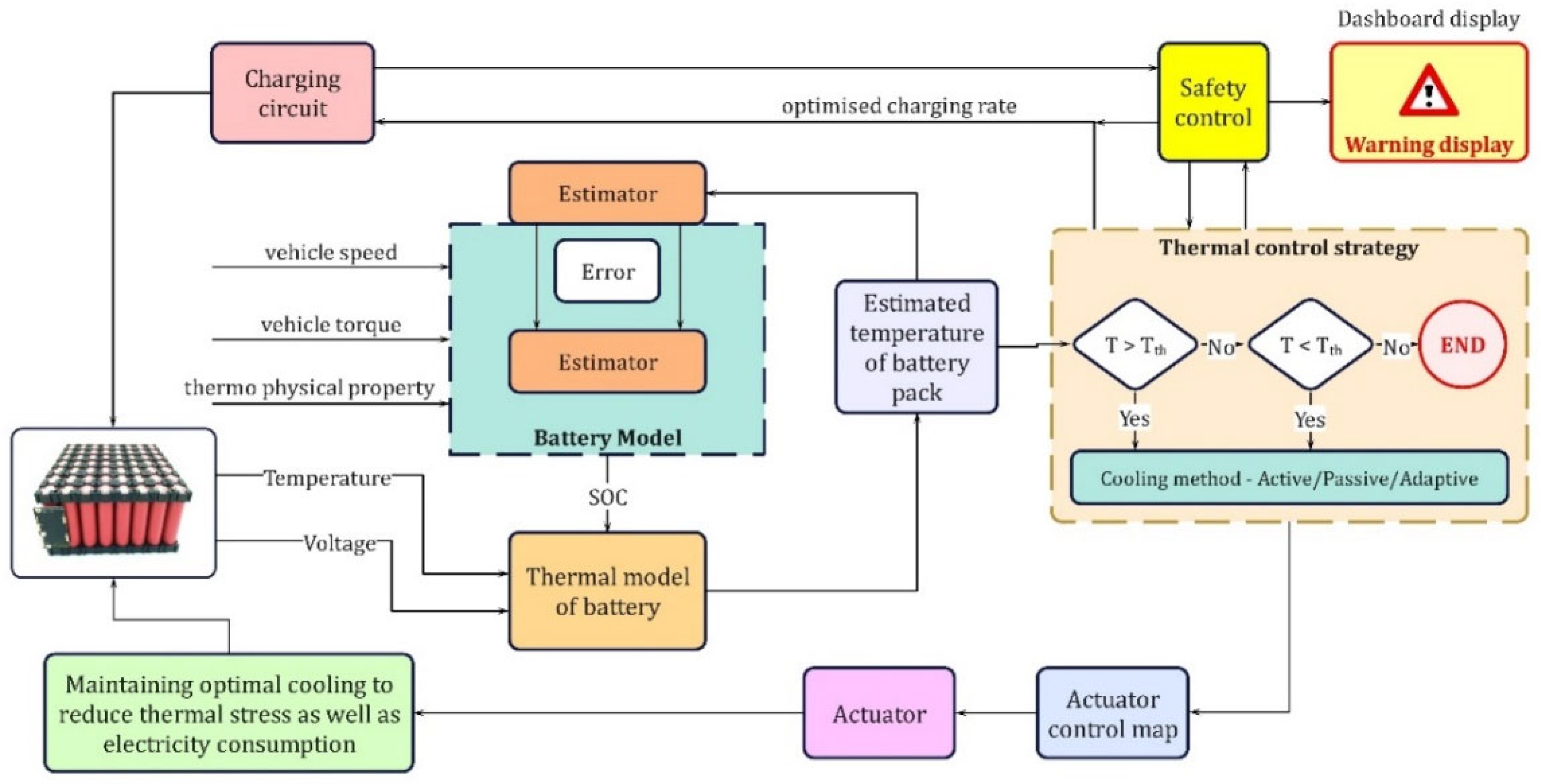
7.1. Internal Architecture of Battery Thermal Management System in Electric Vehicle

One of the crucial parts of the BTMS is the thermal model of the battery which is responsible for the accurate estimation of the battery pack temperature. It takes temperature and voltage readings, as well as SOC, from the state estimation module as inputs. Based on these inputs, the mathematical model present in the thermal model calculates the temperature distribution within the battery pack. From this, the average temperature value is computed and given as input to the thermal control strategy module. A logic-based algorithm will determine which cooling method to adopt (in case more than one option is available) and accordingly send signals to the corresponding actuator. A BTMS control module is responsible to maintain optimal cooling and ensure that the temperature is in the optimum range during charging. For ensuring battery pack temperature within the safe operating limits numerous cooling techniques have been developed. A well-designed BMS with proper BTMS would ensure longer battery life and higher efficiency. The developed architecture of a BTMS is shown in Figure 18.

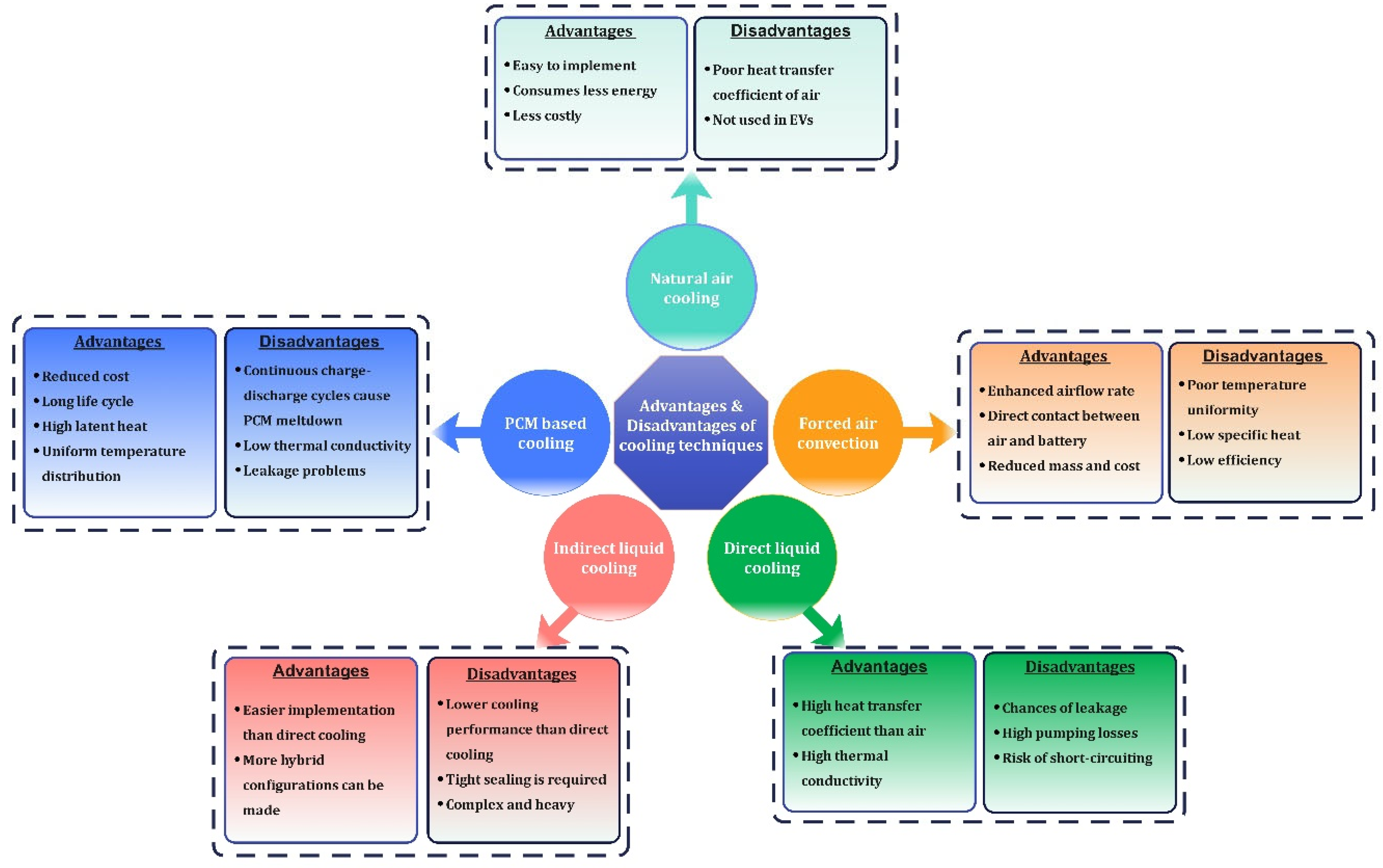
7.2. Battery Thermal Management System in Electric Vehicles

The battery thermal management system aims to control the battery temperature by employing several cooling strategies. BTMSs in EVs are mainly classified based on power consumption (e.g., active or passive), heat transfer medium (e.g., air, liquid, PCM), contact between coolant and battery surface (e.g., direct or indirect cooling), and other strategies (e.g., HP-based, hybrid TMS) [18,147,148]. The active systems consume extra energy to power auxiliary units, such as fans or pumps [149], which are usually employed in air and liquid cooling systems. Passive systems rely on special design considerations to supplement heat removal, such as PCMs or HPs. Active systems have better heat dissipation capacity; nevertheless, they are complex in design and costly, whereas passive systems are less costly and easily implementable but less efficient in dissipating heat. The advantages and disadvantages of several cooling systems are demonstrated in Figure 19. A critical review of various thermal management systems is provided in the upcoming section. Prominent areas of investigation for different BTMSs in electric vehicles are tabulated in Table 7.

7.2.1. Air-Cooled BTMS

Air-cooled systems are widely used in EVs due to their simple and less costly design, ease of maintenance, low weight, and direct access to air [173]. They are categorized as natural or forced convection. Natural convection systems have a simple structure, but poor temperature uniformity among cells. To mitigate this issue, although forced convection consumes additional power and is costly, it has become a widespread solution over natural convection [174]. It can cool the battery pack using either external ambient air or cabin air or an evaporator of an HVAC system [175]. Several air-cooled TMSs have been developed based on modifications in battery pack configuration, cell spacing, air-flow channels, and the position and number of air inlets and outlets. The performances of J-type, U-type, and Z-type channel configurations are enhanced using surrogate-based optimization [176]. The best cooling performance is obtained when the inlet and outlet vents are placed symmetrically on different sides with baffle plates [151]. Temperature uniformity and maximum temperature of BTMS with unidirectional airflow (UAF) are enhanced by employing a reciprocating flow of air (RAF) [155,156,177,178]. For cylindrical batteries, an aligned cell configuration gives the best cooling performance and consumes the least space over staggered and cross configurations [179]. The use of air guided fins or a porous metal foam embedded flow channel with pin fins can significantly improve thermal management in the battery pack [180,181]. Despite several advancements, because of the low heat transfer coefficient of air, air cooling is inefficient and unable to provide a uniform temperature in high-power LIBs. Thus, liquid cooling has been introduced owing to the high heat transfer capability of liquids over air.

7.2.2. Liquid-Cooled BTMS

Liquid-cooled systems are preferred in high-power and most practical applications. The high heat capacity and heat transfer coefficient of liquids make them a better alternative to air [182]. They are classified based on the type of contact with the heat transfer fluid (HTF): direct and indirect. In the former, the HTF makes direct contact with the battery cells, either by making the coolant flow through the cell surface, or by immersing the battery pack into the HTF, whereas, the HTF is circulated around the cells via cold plates in the latter [18]. Among the predominantly used HTFs, water, mineral oil, and silicone oil are used in direct-contact cooling; silicone and mineral oils give better cooling performance than water and air-cooling owing to their high heat transfer rate [183,184]. Mixing of Al2O3 nanofluid particles with water effectively reduces the mean temperature (Tmean) of the battery because of Al2O3’s higher thermal conductivity [185]. For immersion cooling, using ammonia, liquid propane, hydrofluoric ether, perfluoro ketone or refrigerant HE-7000, effectively reduces the battery surface temperature [186,187]. For indirect cooling, different flow configurations of cold plates, such as parallel or serpentine, have been studied. The use of U-type micro-channel cold plates with alternating single inlet and outlet channels reduced the maximum temperature (Tmax) and maximum temperature gradient (ΔTmax) by 32.2% and 950.1% respectively over a parallel flow pattern [188]. A parallel circular mini-channel cold plate design for prismatic LiFePO4 cells [189] and streamline-shaped mini channel cold plates [190] showed enhanced cooling rates and uniform temperature distribution. Because of their viability, more research is being focused on improving liquid-cooling methods using heat pipes or PCMs in conjunction with them to further maintain the optimal temperatures.

7.2.3. PCM-Based BTMS

The liquid and air-cooled BTMS work best with an active system; however, a better alternative is the PCM-based BTMS that can also function as a passive system [191]. Their latent heat absorption capacity during melting and solidifying is high [192]. Due to the poor thermal conductivity of pure paraffin [167], metal foams, metal fins, and carbon materials are used with PCM, and, thus, CPCMs are used to improve the thermal conductivity of the system. The thermal conductivity of PCM improved significantly with the use of metal-oxide nanoparticles, such as TiO2, ZnO, SiO2, and Fe2O3 [193]. The wetted foam soaked in n-octadecane gave a reduced Tmax over dry foam-based PCM [194]. Al foam + paraffin expedited the melting process of paraffin considerably; hence, the time taken for heat removal was decreased [195]. Implementation of aluminum-nitrite-based CPCM in a Li-ion battery improved the thermal conductivity by 192.63% along with improving structural strength [196]. The use of expanded graphite (EG) (15–20% mass fraction) was found to improve thermal conductivity and curtail PCM leakage (0.38 wt% lower) [197,198]. To overcome the leakage in PCM, several designs with improved anti-leakage properties have been developed, such as nanosilica + EG and high-density polyethylene (HDPE) + nano-silver + EG [199,200]. A BTMS based on EG + low-density polyethylene (LDPE) + paraffin, coupled with low fins, gave reduced Tmax and ΔTmax [201]. Recently heat pipes + PCM cooling systems have been developed owing to their high thermal conductivity [202]. PCM-based systems are often integrated with traditional TMSs, such as air/liquid-cooled systems or HP or thermoelectric coolers, for further performance enhancement.

7.2.4. Hybrid BTMS

It can be seen that traditional cooling techniques, such as air-cooling, liquid-cooling, and PCM, are capable of meeting the requirements of thermal management systems in EVs. In addition, several types of cooling techniques can be integrated with one another to exploit the merits of one technique, while overcoming the drawbacks of the other. Various PCM cooling systems have been integrated with conventional air and liquid-cooled systems. To preclude heat build-up in PCMs, PCMs with forced-air cooling [203], addition of Cu foam to PCM with active liquid cooling [204], and RT44HC-paraffin/EG CPCM (6 wt% EG) with liquid cooling [205] configurations are used. They enhance the thermal conductivity and temperature uniformity over pure PCM. For prismatic batteries, paraffin/EG/HDPE/nano-silver CPCM with a single water channel during rapid charge/discharge cycles reduced Tmax and ΔTmax by 35.32% and 64% respectively [200]. HP-based TMSs, such as HP + cold plates, successfully dissipated a 50W heat load per cell and maintained Tmax below 55 °C [206]. Further, a PCM/OHP-based TMS provided more efficient cooling performance than an OHP-based TMS. HP + forced convection, coupled with fins, reduced the Tmax by 67.17% over ambient cooling [207]. Numerous other BTMSs, such as thermoelectric-cooling (TEC), mist cooling, and refrigeration cooling have been developed for efficiently cooling EV batteries [208,209,210]. Having presented a thorough coverage of the control approaches of BMS in EVs, it is also essential to consider their implementation in real-time EVs. The subsequent section deals with the instances of features of BMS implemented in real-time EVs.

8. Characteristic Features of BMS Implemented in Real-Time Vehicles

There is no rule of thumb for choosing the correct BMS for a particular application and its selection solely depends on the requirements imposed by the system. BMSs are classified into three categories in real-time applications: centralized, modular, and distributed. When selecting a BMS for EV application, certain characteristics may be considered such as: accuracy for voltage, current, temperature, and SOC measurements, the range for monitoring these quantities, the number of cells, type of balancing, communication protocol, data logging location, battery compatibility, and robustness and flexibility to protect the battery against adverse conditions [211]. This section casts some light on state-of-the-art BMSs that have been implemented in real-time vehicles along with their battery configurations, as listed in Table 8. The first is the Tesla Model S whose P85’s battery pack comprises a total of 7104–18,650 cells divided into 16 modules. Each module follows a 6s74p configuration—6 cells in series and 74 in parallel. The BMS used here is a TI’s bq76PL536A-Q1 which monitors SOC, SOD, temperature, overcharge and under-discharge [212]. A serial peripheral interface (SPI) is used for communication between slave and master BMS modules [213]. The cooling system of the Model S’s battery pack adopts a liquid cooling system with serpentine-shaped cooling pipes. The mixture of water-ethylene glycol is passed through the pack [32]. Next is the Mitsubishi i-MiEV. Its battery pack is composed of 88 prismatic cells divided into ten modules of eight cells and two modules of four cells. These modules use a combination of PCB and LTC6802G-2 [214] battery monitoring ICs called cell management units (CMUs) that perform voltage, current and temperature monitoring, fault detection, passive cell-balancing, etc. The CMUs are connected to one another and to the battery management unit (BMU) via a CAN bus. i-MiEV’s cooling system employs forced air convection guided by fans [15]. The Smart EQ Fortwo by Daimler AG uses the battery manufactured by Deutsche Accumotive. It consists of 90 serially connected pouch cells with welded connections. These cells are arranged in three rows with a total of six monitoring ICs placed on PCBs with specifications similar to TI’s bq76PL536A. The connections between the monitoring ICs and the master BMS, and with other systems, are established via a CAN network. For cooling the battery pack, cold-plate-based liquid cooling is adopted with an ethylene glycol-water mixture as the coolant [215]. Another battery pack from Volkswagen e-Up contains 17 modules connected in series. Each of the 17 modules consists of 12 prismatic cells. The Maxim MAX11068 is employed for measuring the voltage, monitoring temperature, cell-balancing, and fault detection [216]. It is aided by the MAX11081 as a secondary protection device [217]. Communication between slave and master BMS modules is achieved using an I2C bus. There is no literature available on the cooling system for e-Up’s battery. Lastly, the battery pack used by the Audi e-tron is a three-yuan power battery developed by the Ningde era. It is made up of 36 modules, each comprising 12 batteries with 4p3s configuration. e-tron’s battery uses a distributed BMS. It contains a battery management controller (BMC-master unit), cell module controller (CMC-slave unit), and battery junction box (BJB). CMC detects the cell voltage, and temperature and achieves balancing. A unit in the BJB manages the battery voltage, bus current and insulation resistance of the pack. CMC and BJB communicate with BMC via a CAN or daisy chain [218]. However, the detailed specifications for e-tron’s BMS module are not available. To cool the battery, a glycol/water coolant is passed through cooling plates and a heat-conducting paste is used between the plates and the cell space for heat transfer [219]. For high power demand, the coolant circuit is coupled with the refrigerant circuit of the air-conditioning system to provide intensive cooling. Despite the commercialization of BMS with highly advanced control approaches, for estimating states, balancing voltage levels, and maintaining temperature levels, numerous challenges exist for BMS towards enhancing the safety of the battery which has become an area of focus among researchers and automakers.

9. Concept of Intelligent BMS to Tackle the Issue of Battery Safety

The primary role of a BMS is to ensure the safe operation of the battery, and, thereby, to reduce the risks of hazards and ensure long battery life. In order to fulfil this requirement, BMSs must ensure fault-free working of functions, such as cell monitoring, state estimation, fault diagnosis, and the uninterrupted communication between modules, otherwise it may result in system failure. Meeting these requirements has become a major concern for existing BMSs. Therefore, to tackle issues related to the safety of the battery, an intelligent BMS using advanced technologies, such as IoT, cloud-computing, artificial intelligence (AI), and data science is being tested and developed.

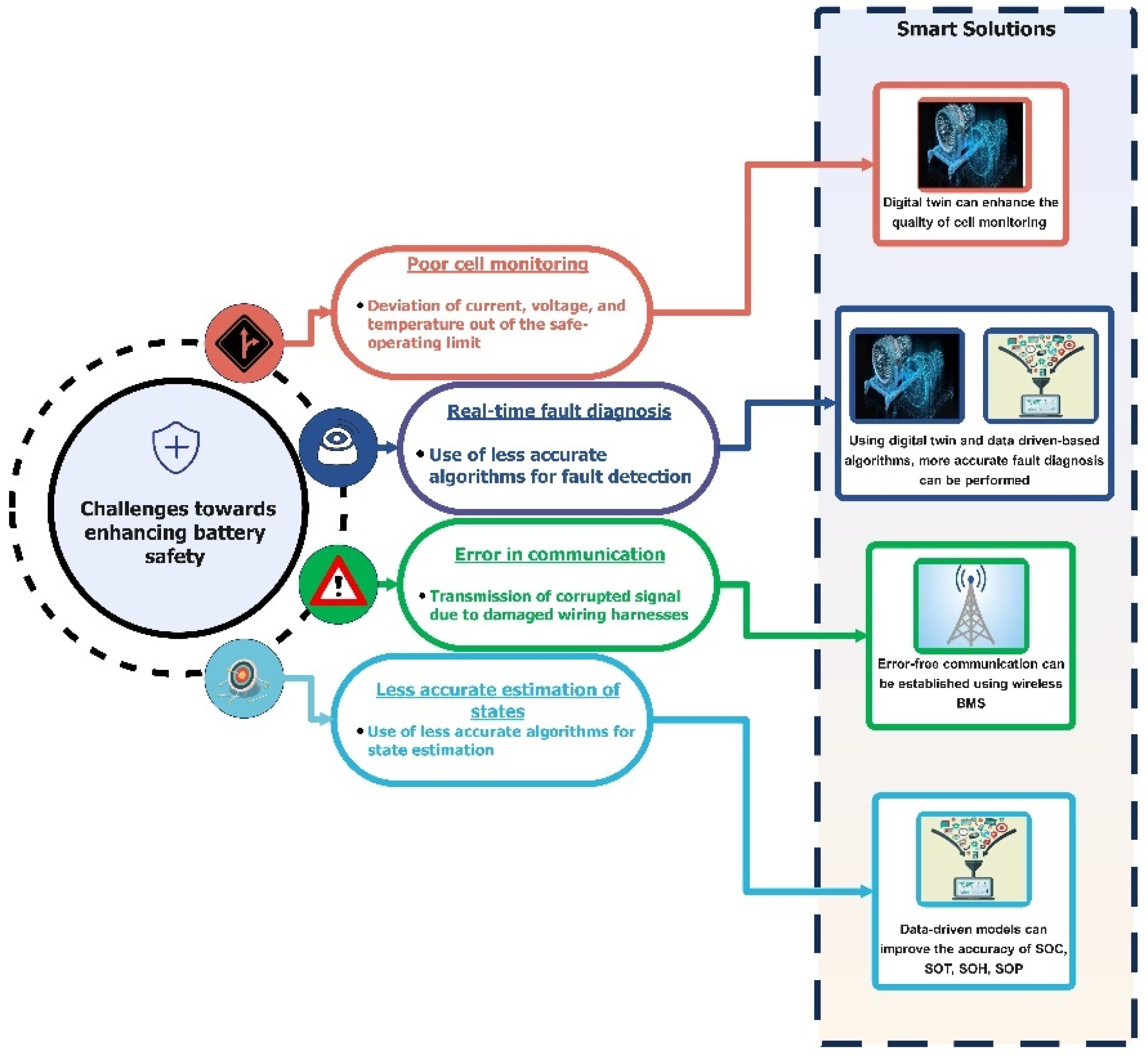
9.1. Challenges for BMS towards Enhancing Battery Safety

The safety of batteries is achieved when certain conditions are met with regards to BMSs, such as maintaining input quantities, including current, voltage, and temperature, within safe-operating limits; accurate estimation of battery states; accurate real-time fault diagnosis [16]; and error-free communication between different control modules within and outside of the BMS. Failure to meet these conditions results in battery faults, such as overcharging, over-discharging, thermal runaway, internal short-circuit, external short-circuit and so on [220]. These faults may bring about hazards, such as fire, explosion, deflagration, electric shock, etc. [221]. Deviation of input quantities outside of safe limits may cause overcharging/over-discharging of battery. To illustrate, feeding an incorrect voltage value to the cell-balancing module will lead to overcharging or over-discharging of more than one cell. Similarly, error occurs when the communication signal is corrupted due to external impacts, such as damage to the wiring harnesses in the BMS. This could result in failure of the CAN network, leading to erroneous data transfer between control modules. Further, inaccuracies in estimating battery states could cause a voltage imbalance among cells and compromise the thermal behavior of the battery, which can result in overcharging/discharging, or overheating. It is challenging to develop a battery model that can mimic all the dynamic characteristics of a battery accurately due to uncertain operating conditions. Furthermore, existing fault diagnosis modules use model-based algorithms to predict fault features for detecting battery faults. However, certain fault features are determined at a later stage of system failure. Hence, accurate and more real-time fault diagnosis systems cannot be implemented [222]. These aspects have become a major concern for BMSs in enhancing battery safety. As the safety of the system is the prime concern, the traditional BMS is unable to manage useful data collected which can be used for safety assessment due to data computing and storage limitations. Hence, adopting new technologies in developing intelligent BMS is a current focus of research considering safety as well as operational excellence. A schematic representation of the challenges and smart solutions is provided in Figure 20. Using the benefits of cloud storage and cloud computing, a novel cloud-based battery monitoring and fault diagnosis model can be developed. This model uses a cyber-physical platform for measuring input quantities and for fault diagnosis [222]. Several data-driven models can be incorporated for more accurate estimation of battery states and fault features to detect faults. Similarly, a wireless battery management system (WBMS), which comes with enhanced fault tolerance, can eliminate the communication-related issues that arise from the failure of wiring harnesses [223].

9.2. Intelligent Battery Management Systems in EVs

To overcome the issues of the data computing and storage limitations of traditional BMSs, researchers are now exploiting the benefits of advanced technologies, such as big data, IoT, cloud-computing, AI and data science. Existing battery models are model-based electrochemical or ECMs. They require more time and effort to model. Furthermore, the parameters required to model them are difficult to obtain given the non-linearities that are associated. To tackle these hurdles, data-driven models are being employed. Data-driven models, with the help of ample data, can make predictions or decisions with only minimal human intervention. Neural networks (NN), regression models, support vector machine (SVM) models, fuzzy-based estimations and neural networks, ensemble bagging, and ensemble boosting are some of the algorithm models [224]. Among these models, neural networks with fuzzy logic and SVM have shown good results. Nowadays, various algorithms are used in combination to further improve the accuracy and speed without increasing computational requirements. These data-driven models estimate battery states and fault features for fault diagnosis more accurately. IoT and cloud-based wireless communication between the hardware and software systems can be seen in various studies. These high fault-tolerance systems can eliminate communication errors arising due to the failure of wiring harnesses in the conventional BMS. Similarly, cloud-based, smart BMSs can overcome the issue of large data collection and its on-board computation by allowing the control systems to deliver functionality without the need for high-end hardware. Using a cyber-physical platform, all the data collected by the sensors are sent to cloud platforms where a digital-twin for the battery is built using the collected data and several fault diagnostic algorithms are evaluated [221]. Furthermore, the incessant transmission of data between the BMS and vehicle using data farms would also help in the creation of the digital twin of the system. These data farms have exceptional computational powers and unlimited storage, as well as higher reliability. To ensure secure and private data transmission, TCP/IP and message queuing telemetry transport (MQTT) protocols can be used [221]. Additionally, with the majority of the data being on the cloud, it will make it easier for the end-user to analyze various data using mobile/PC applications. Recent developments, such as Bluetooth-5.3, and the upcoming Wi-Fi-7, will facilitate superfast data transfer between components. Hence, there is a great scope for intelligent BMSs, while state-of-the-art smart BMS techniques, as shown in Figure 21, have proven that these methods give a boost to the vehicle in terms of data handling and computational performance along with enhancing battery safety.

10. Challenges in Design and Development of BMS

Despite so many designs and control techniques, a researcher will experience different challenges while designing and developing an effective BMS for EV applications. The challenges may be linked to charging, thermal management, battery life, etc. These issues must be addressed for the safe, reliable and efficient operation of battery-powered electric vehicles. Hence, the prominent challenges during BMS development that need attention are presented below to stimulate future engineers to divert their research focus towards addressing them. This is schematically presented in Figure 22.
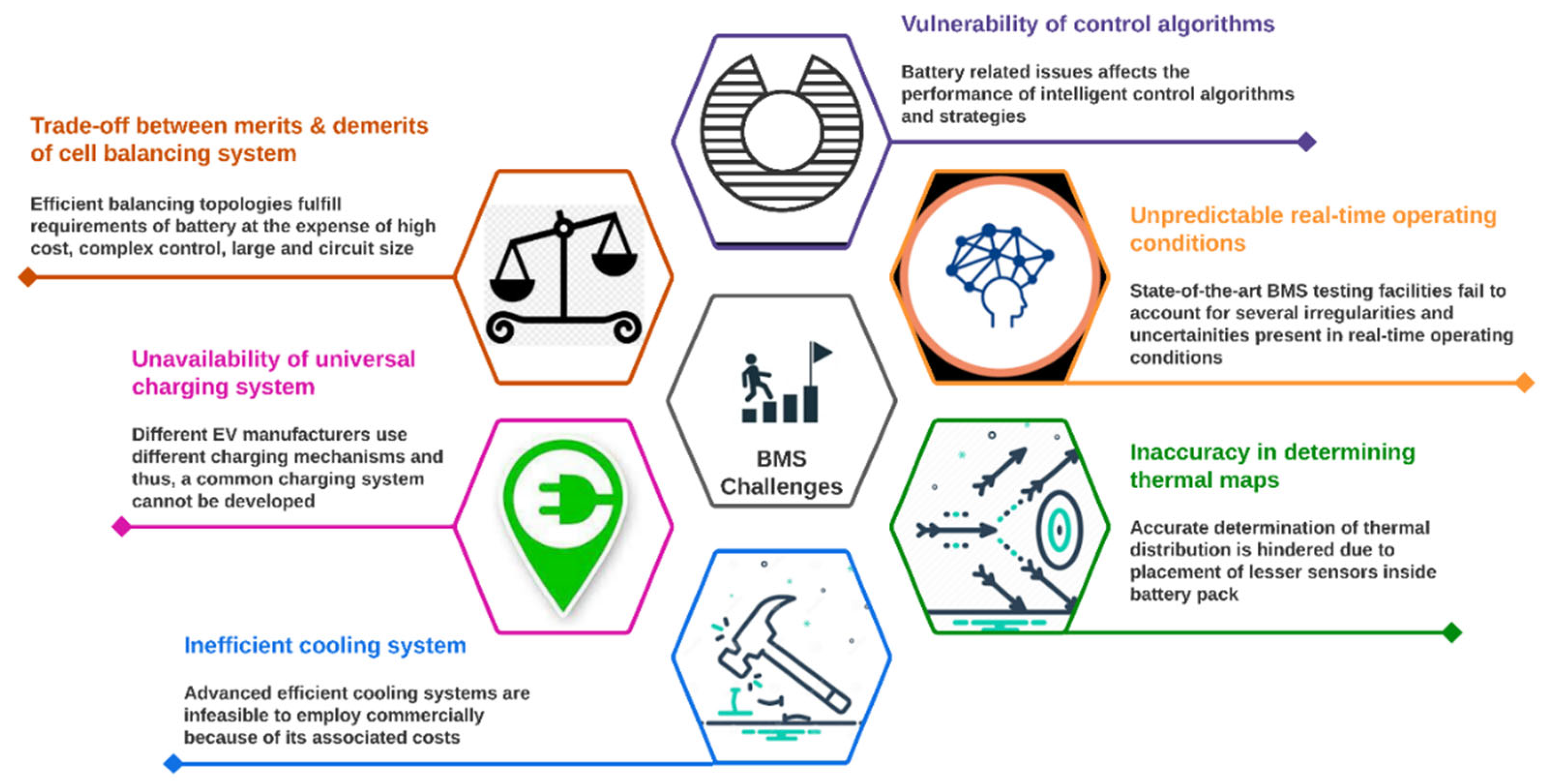
  • State-of-the-art BMS testing is carried out in laboratories and testbeds, whereas real-life on-road operating conditions are not always equivalent to laboratory testing conditions. Hence, the quantification of various uncertainties and their effects on BMS performance needs to be evaluated. This is a hurdle for the self-evaluation of the BMS, since parameters such as capacity, power fade, temperature, ageing, etc., are sometimes complex to predict even using mathematical models.
  • The existing battery pack relies on temperature sensors for the thermal data. However, for a long battery string, it is not feasible to place sensors on all the cells, thus sensors are placed at only a few locations. The readings from these sensors are given to the mathematical model, wherein an algorithm predicts the temperature distribution inside the battery pack. Accurate determination of these thermal maps is still a big challenge. Furthermore, the existing battery packs are still not completely safe and are highly flammable. Hence, another significant challenge is imposed by the improved design of battery packs to protect them from thermal runaways.
  • For longevity, as well as the efficient working of the cells, an optimal temperature range should be maintained. Although recent thermal management designs offer increased efficiency, they pose challenges concerning cost and compactness. Most companies have adopted liquid cooling systems with some modifications, owing to their comparatively low cost and high efficiency. Nevertheless, the techniques which hold high potential are still not feasible for the commercial market. This, in turn, introduces a challenge to battery manufacturers to develop compact, efficient and cost-effective thermal management techniques.
  • To charge a battery according to requirements, a communication system needs to be established between the state estimation module and the charger for communicating the SOC of the battery. This communication line between the charger and the battery is developed through a system management bus which allows communication of battery-related data, such as the charging/discharging current, voltage, and SOC [225]. However, most EV manufacturers use different communication methods, due to which it becomes impossible to design a universal charger that can serve the purpose of all EVs. To tackle this issue, a universal communication method needs to be developed.
  • In EVs, control mechanisms that are easy to implement, simple, and cheap are always preferred. However, in employing a cell-balancing topology, merits and demerits are always concomitant. For instance, passive methods are simple to control and cheaper, nevertheless they are the least efficient and the slowest. Similarly, inductors/transformers offer faster balancing speed and high efficiency at the cost of intelligent control to overcome design difficulties, and thus are costly. While SC-based methods offer excellent balancing efficiency with economical design, balancing speed is poor. Several converters are widely used in charge balancing applications in EVs because of their remarkable balancing efficiency, balancing speed, low current and voltage stresses, but at the cost of complicated intelligent control and high cost [140]. Thus, a balancing configuration that possesses all the merits and is economical, extensible and reliable at the same time is greatly needed.
  • Different battery chemistries affect the accuracy of state estimation despite using the same algorithm [226]. Similarly, with increase in ageing cycles, degradation of capacitance, internal resistance, structural changes in cathode and anode, and growth of solid electrolyte interphase thickness affect the ability of control algorithms to accurately estimate the battery SOC, SOH and RUL in BMSs [227,228]. Moreover, charge imbalance could cause deviation in state estimation algorithms and affect the intelligent control strategies of the safety management module inside the BMS [229]. Other issues that affect performance are thermal runaway [230,231], loss of battery capacity, and power fading. Hence, research needs to be undertaken to build control algorithms and strategies immune to battery issues.

11. Summary and Future Scope

The present review is a compilation of various control techniques and their critical analysis in a BMS. By presenting the generalized framework of internal architecture of BMS, SOC, cell-balancing and BTMS modules, beginners as well as experienced researchers can readily analyze the workflow during actual driving conditions. This will help to obtain a complete and broad overview of the BMS in a holistic manner. All the studies reviewed in this paper are based on previous research and experimental work focused on improving BMS efficiency. To begin with, the numerous battery models were discussed and reviewed according to their classification. Furthermore, an in-depth investigation was undertaken regarding various important BMS modules, such as state estimation, cell-balancing and thermal management systems. The control approaches implied in these were discussed and their key functions were showcased. It was observed that every control strategy has its advantages and disadvantages, and sometimes researchers had to consider a trade-off between accuracy and complexity. However, some control strategies were found to be more efficient than others in some control modules. For the SOC estimation control techniques, robust EKF, IPSO-EKF and the adaptive unscented Kalman filter were found to give less than 1% error, compared to others. The highest error value was observed in the time-delay neural network method. Similarly, for the SOH estimation control techniques, multilayer perception and the artificial neural network method were the only ones with less than 1% error. On the other hand, for the SOP estimation control techniques, only the genetic algorithm gave less than 1% error, the rest all having relatively higher error percentages. Similarly, for cell-balancing, multiple studies suggest that resonant and modularized configurations are highly efficient, especially in SC-based configurations. The star-structured LC resonant switched capacitor and the switched capacitor with modularized chain structure gave efficiencies above 98%. However, for BTMS, the latest trend observed was the use of liquid-cooled battery packs, due to their relatively low cost, efficient cooling and simplicity of implementation. A proper balance between these modules within a BMS resulted in effective power management and vehicle operation. This review also highlights various prominent challenges which researchers currently face in developing BMS. The evolving field of E-mobility will encourage readers to address such challenges and bridge the gaps so that better BMSs are developed which can draw out the maximum potential of the Li-ion battery in the near future. Improved BMSs will ensure a safer driving experience and extended battery lifetime which is the need of the hour given the promising shift towards E-mobility. The undermentioned suggestions are provided to enhance BMS performance in the future:
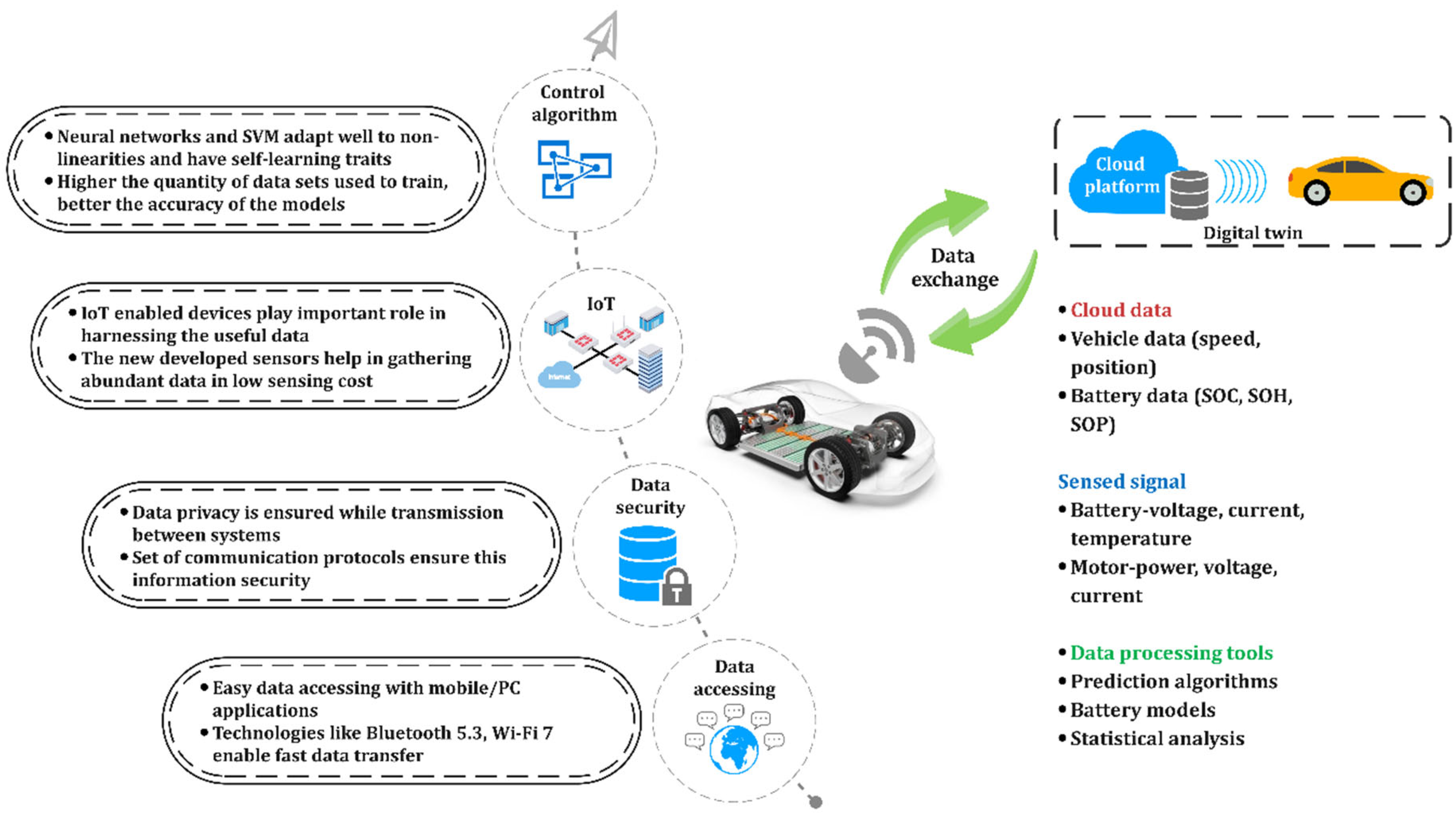
  • The next-generation concept of data handling in BMS is through a distributed system of onboard battery management, as well as on the cloud platform. In this way, high precision and complex real-time estimation can be carried out on a cloud platform.
  • A novel active cell-balancing topology based on wireless power transfer has emerged recently. At present, research in this domain is embryonic. WPT-based systems offer several advantages, such as minimized inductive losses due to the absence of a magnetic core, small size, versatile and modular structure, and lower cost.
  • In recent times, several intelligent control algorithms for state estimation have been combined and hybrid algorithms developed. These algorithms have demonstrated superior accuracy in predicting battery SOC over a single algorithm. However, the cumbersome combination of algorithms leads to an increase in mathematical complexity and estimation time which often gives undesirable results. Hence, further research in the hybridization of control algorithms is needed to assess the practicability of a particular hybrid algorithm. This will help develop an efficient hybrid control algorithm that will enhance the overall performance of BMSs.
  • The use of nano-particles in PCM or liquid-based cooling systems will pave the way for enhanced cooling rates. Various metal-, organic- and inorganic-based nanoparticles are being researched. Carbon-based nanostructures as well graphite-based nanocomposites have shown good results in laboratory conditions.
  • Immersion cooling is also being hailed as the future of BTMS. It is more efficient and can also support extreme fast charging (XFC). These systems are, however, costly, and the liquid used is also not highly efficient. However, with more research and development they will become available for commercial use.

Author Contributions

Conceptualization, B.A.; methodology, B.A.; validation, B.A., C.K. (Chidambaram Kannan), S.D.A. and V.I.; formal analysis, B.A. and C.K. (Chidambaram Kannan); writing, A.S.W., D.P. and A.J.; review and editing, B.A., C.K. (Chellapan Kavitha)., B.M., S.D.A., V.I. and B.A.; supervision, B.A.; project administration, B.A.; funding acquisition, B.A., C.K. (Chidambaram Kannan) and B.M. All authors have read and agreed to the published version of the manuscript.

Funding

This research was funded by the Royal Academy of Engineering, UK grant number DIA-2022-150.

Institutional Review Board Statement

Not applicable.

Informed Consent Statement

Not applicable.

Acknowledgments

The authors would like to thank the management of the Vellore Institute of Technology, Vellore for the facilities provided during the execution of this work. Further authors wishes to acknowledge Loughborough University, UK for the funding the Open Access of this articles under the Innovate UK 78938-506185.

Conflicts of Interest

The authors declare no conflict of interest.

References

  1. Wang, Q.; Jiang, B.; Li, B.; Yan, Y. A Critical Review of Thermal Management Models and Solutions of Lithium-Ion Batteries for the Development of Pure Electric Vehicles. Renew. Sustain. Energy Rev. 2016, 64, 106–128. [Google Scholar] [CrossRef]
  2. Bao, Y.; Zhang, X.; Zhang, X.; Yang, L.; Zhang, X.; Chen, H.; Yang, M.; Fang, D. Free-Standing and Flexible LiMnTiO4/Carbon Nanotube Cathodes for High Performance Lithium Ion Batteries. J. Power Sources 2016, 321, 120–125. [Google Scholar] [CrossRef]
  3. Zhang, Z.; Li, Q.; Li, Z.; Ma, J.; Li, C.; Yin, L.; Gao, X. Partially Reducing Reaction Tailored Mesoporous 3D Carbon Coated NiCo-NiCoO2/Carbon Xerogel Hybrids as Anode Materials for Lithium Ion Battery with Enhanced Electrochemical Performance. Electrochim. Acta 2016, 203, 117–127. [Google Scholar] [CrossRef]
  4. Zhang, L.M.; Wang, X.B.; Tao, S.; Wu, G.X.; Su, X.Z.; Wei, S.Q.; Zhao, H.F.; Chu, W.S. Layered Li2RuO3-LiCoO2 Composite as High-Performance Cathode Materials for Lithium-Ion Batteries. Mater. Lett. 2016, 179, 34–37. [Google Scholar] [CrossRef]
  5. Tao, Y.; Rui, K.; Wen, Z.; Wang, Q.; Jin, J.; Zhang, T.; Wu, T. FeS2 Microsphere as Cathode Material for Rechargeable Lithium Batteries. Solid State Ionics 2016, 290, 47–52. [Google Scholar] [CrossRef] [Green Version]
  6. Rosedhi, N.D.; Idris, N.H.; Rahman, M.M.; Din, M.F.M.; Wang, J. Disordered Spinel LiNi0.5Mn1.5O4 Cathode with Improved Rate Performance for Lithium-Ion Batteries. Electrochim. Acta 2016, 206, 374–380. [Google Scholar] [CrossRef]
  7. Zhao, C.; Yin, H.; Ma, C. Quantitative Evaluation of LiFePO4 Battery Cycle Life Improvement Using Ultracapacitors. IEEE Trans. Power Electron. 2016, 31, 3989–3993. [Google Scholar] [CrossRef]
  8. Omar, N.; Verbrugge, B.; Mulder, G.; Van Den Bossche, P.; Van Mierlo, J.; Daowd, M.; Dhaens, M.; Pauwels, S. Evaluation of Performance Characteristics of Various Lithium-Ion Batteries for Use in BEV Application. In Proceedings of the 2010 IEEE Vehicle Power and Propulsion Conference, Lille, France, 1–3 September 2010. [Google Scholar] [CrossRef]
  9. Labrini, M.; Scheiba, F.; Almaggoussi, A.; Larzek, M.; Braga, M.H.; Ehrenberg, H.; Saadoune, I. Delithiated LiyCo0.8Ni0.1Mn0.1O2 Cathode Materials for Lithium-Ion Batteries: Structural, Magnetic and Electrochemical Studies. Solid State Ionics 2016, 289, 207–213. [Google Scholar] [CrossRef]
  10. He, X.; Wu, L.; Man, X.; Zhang, X.; Wu, X.; Jia, W. A High-Voltage High-PSRR Power Management Circuit for BMS Chip of New Energy Vehicle. In Proceedings of the 2016 13th IEEE International Conference on Solid-State and Integrated Circuit Technology (ICSICT), Hangzhou, China, 25–28 October 2016; pp. 1387–1389. [Google Scholar] [CrossRef]
  11. Wang, Y.; Tian, J.; Sun, Z.; Wang, L.; Xu, R.; Li, M.; Chen, Z. A Comprehensive Review of Battery Modeling and State Estimation Approaches for Advanced Battery Management Systems. Renew. Sustain. Energy Rev. 2020, 131, 110015. [Google Scholar] [CrossRef]
  12. Liu, K.; Li, K.; Yang, Z.; Zhang, C.; Deng, J. An Advanced Lithium-Ion Battery Optimal Charging Strategy Based on a Coupled Thermoelectric Model. Electrochim. Acta 2017, 225, 330–344. [Google Scholar] [CrossRef]
  13. Huang, L.; Zhang, Z.; Wang, Z.; Zhang, L.; Zhu, X.; Dorrell, D.D. Thermal Runaway Behavior during Overcharge for Large-Format Lithium-Ion Batteries with Different Packaging Patterns. J. Energy Storage 2019, 25, 100811. [Google Scholar] [CrossRef]
  14. Pesaran, A.; Santhanagopalan, S.; Kim, G.-H. Addressing the Impact of Temperature Extremes on Large Format Li-Ion Batteries for Vehicle Applications. In Proceedings of the 30th International Battery Seminar, Fort Lauderdale, FL, USA, 11–14 March 2013. [Google Scholar]
  15. Lelie, M.; Braun, T.; Knips, M.; Nordmann, H.; Ringbeck, F.; Zappen, H.; Sauer, D.U. Battery Management System Hardware Concepts: An Overview. Appl. Sci. 2018, 8, 534. [Google Scholar] [CrossRef] [Green Version]
  16. Lu, L.; Han, X.; Li, J.; Hua, J.; Ouyang, M. A Review on the Key Issues for Lithium-Ion Battery Management in Electric Vehicles. J. Power Sources 2013, 226, 272–288. [Google Scholar] [CrossRef]
  17. Du, R.; Hu, X.; Xie, S.; Hu, L.; Zhang, Z.; Lin, X. Battery Aging- and Temperature-Aware Predictive Energy Management for Hybrid Electric Vehicles. J. Power Sources 2020, 473, 228568. [Google Scholar] [CrossRef]
  18. Wu, W.; Wang, S.; Wu, W.; Chen, K.; Hong, S.; Lai, Y. A Critical Review of Battery Thermal Performance and Liquid Based Battery Thermal Management. Energy Convers. Manag. 2019, 182, 262–281. [Google Scholar] [CrossRef]
  19. Liu, H.; Wei, Z.; He, W.; Zhao, J. Thermal Issues about Li-Ion Batteries and Recent Progress in Battery Thermal Management Systems: A Review. Energy Convers. Manag. 2017, 150, 304–330. [Google Scholar] [CrossRef]
  20. Xiong, R.; Li, L.; Tian, J. Towards a Smarter Battery Management System: A Critical Review on Battery State of Health Monitoring Methods. J. Power Sources 2018, 405, 18–29. [Google Scholar] [CrossRef]
  21. Liu, K.; Li, K.; Peng, Q.; Zhang, C. A Brief Review on Key Technologies in the Battery Management System of Electric Vehicles. Front. Mech. Eng. 2019, 14, 47–64. [Google Scholar] [CrossRef] [Green Version]
  22. Shen, M.; Gao, Q. A Review on Battery Management System from the Modeling Efforts to Its Multiapplication and Integration. Int. J. Energy Res. 2019, 43, 5042–5075. [Google Scholar] [CrossRef]
  23. Xiong, R.; Ma, S.; Li, H.; Sun, F.; Li, J. Toward a Safer Battery Management System: A Critical Review on Diagnosis and Prognosis of Battery Short Circuit. iScience 2020, 23, 101010. [Google Scholar] [CrossRef]
  24. Xing, Y.; Ma, E.W.M.; Tsui, K.L.; Pecht, M. Battery Management Systems in Electric and Hybrid Vehicles. Energies 2011, 4, 1840–1857. [Google Scholar] [CrossRef]
  25. Gabbar, H.A.; Othman, A.M.; Abdussami, M.R. Review of Battery Management Systems (BMS) Development and Industrial Standards. Technologies 2021, 9, 28. [Google Scholar] [CrossRef]
  26. Lin, Q.; Wang, J.; Xiong, R.; Shen, W.; He, H. Towards a Smarter Battery Management System: A Critical Review on Optimal Charging Methods of Lithium Ion Batteries. Energy 2019, 183, 220–234. [Google Scholar] [CrossRef]
  27. Ali, M.U.; Zafar, A.; Nengroo, S.H.; Hussain, S.; Alvi, M.J.; Kim, H.J. Towards a Smarter Battery Management System for Electric Vehicle Applications: A Critical Review of Lithium-Ion Battery State of Charge Estimation. Energies 2019, 12, 446. [Google Scholar] [CrossRef] [Green Version]
  28. Rahimi-Eichi, H.; Ojha, U.; Baronti, F.; Chow, M.Y. Battery Management System: An Overview of Its Application in the Smart Grid and Electric Vehicles. IEEE Ind. Electron. Mag. 2013, 7, 4–16. [Google Scholar] [CrossRef]
  29. Carlucho, I.; De La Vega, R.; Spina, M.; Acosta, G.G. A Modular Battery Management System for Electric Vehicles. In Proceedings of the 2018 IEEE Biennial Congress of Argentina (ARGENCON), San Miguel de Tucuman, Argentina, 6–8 June 2018; pp. 1–6. [Google Scholar] [CrossRef]
  30. Conte, F.V. Battery and Battery Management for Hybrid Electric Vehicles: A Review. Elektrotechnik Inf. 2006, 123, 424–431. [Google Scholar] [CrossRef]
  31. Tomasov, M.; Kajanova, M.; Bracinik, P.; Motyka, D. Overview of Battery Models for Sustainable Power and Transport Applications. Transp. Res. Procedia 2019, 40, 548–555. [Google Scholar] [CrossRef]
  32. Kannan, C.; Vignesh, R.; Karthick, C.; Ashok, B. Critical Review towards Thermal Management Systems of Lithium-Ion Batteries in Electric Vehicle with Its Electronic Control Unit and Assessment Tools. Proc. Inst. Mech. Eng. Part D J. Automob. Eng. 2021, 235, 1783–1807. [Google Scholar] [CrossRef]
  33. Meng, J.; Luo, G.; Ricco, M.; Swierczynski, M.; Stroe, D.I.; Teodorescu, R. Overview of Lithium-Ion Battery Modeling Methods for State-of-Charge Estimation in Electrical Vehicles. Appl. Sci. 2018, 8, 659. [Google Scholar] [CrossRef] [Green Version]
  34. Zhang, C.; Li, K.; McLoone, S.; Yang, Z. Battery Modelling Methods for Electric Vehicles—A Review. In Proceedings of the 2014 European Control Conference (ECC), Strasbourg, France, 24–27 June 2014; pp. 2673–2678. [Google Scholar] [CrossRef]
  35. He, H.; Xiong, R.; Guo, H.; Li, S. Comparison Study on the Battery Models Used for the Energy Management of Batteries in Electric Vehicles. Energy Convers. Manag. 2012, 64, 113–121. [Google Scholar] [CrossRef]
  36. Zhang, L.; Peng, H.; Ning, Z.; Mu, Z.; Sun, C. Comparative Research on RC Equivalent Circuit Models for Lithium-Ion Batteries of Electric Vehicles. Appl. Sci. 2017, 7, 1002. [Google Scholar] [CrossRef] [Green Version]
  37. Tamilselvi, S.; Gunasundari, S.; Karuppiah, N.; Razak Rk, A.; Madhusudan, S.; Nagarajan, V.M.; Sathish, T.; Shamim, M.Z.M.; Saleel, C.A.; Afzal, A. A Review on Battery Modelling Techniques. Sustainability 2021, 13, 10042. [Google Scholar] [CrossRef]
  38. Shrivastava, P.; Soon, T.K.; Idris, M.Y.I.B.; Mekhilef, S. Overview of Model-Based Online State-of-Charge Estimation Using Kalman Filter Family for Lithium-Ion Batteries. Renew. Sustain. Energy Rev. 2019, 113, 109233. [Google Scholar] [CrossRef]
  39. He, H.; Xiong, R.; Zhang, X.; Sun, F.; Fan, J. State-of-Charge Estimation of the Lithium-Ion Battery Using an Adaptive Extended Kalman Filter Based on an Improved Thevenin Model. IEEE Trans. Veh. Technol. 2011, 60, 1461–1469. [Google Scholar] [CrossRef]
  40. Kalogiannis, T.; Hosen, M.S.; Sokkeh, M.A.; Goutam, S.; Jaguemont, J.; Jin, L.; Qiao, G.; Berecibar, M.; Van Mierlo, J. Comparative Study on Parameter Identification Methods for Dual-Polarization Lithium-Ion Equivalent Circuit Model. Energies 2019, 12, 4031. [Google Scholar] [CrossRef] [Green Version]
  41. Liu, X.; Li, W.; Zhou, A. PNGV Equivalent Circuit Model and SOC Estimation Algorithm for Lithium Battery Pack Adopted in AGV Vehicle. IEEE Access 2018, 6, 23639–23647. [Google Scholar] [CrossRef]
  42. He, H.; Xiong, R.; Fan, J. Evaluation of Lithium-Ion Battery Equivalent Circuit Models for State of Charge Estimation by an Experimental Approach. Energies 2011, 4, 582–598. [Google Scholar] [CrossRef]
  43. Zhou, W.; Zheng, Y.; Pan, Z.; Lu, Q. Review on the Battery Model and SOC Estimation Method. Processes 2021, 9, 1685. [Google Scholar] [CrossRef]
  44. Cheng, Q. Porous Graphene Sponge Additives for Lithium Ion Batteries with Excellent Rate Capability. Sci. Rep. 2017, 7, 1–11. [Google Scholar] [CrossRef] [Green Version]
  45. Park, C.; Jaura, A.K. Dynamic Thermal Model of Li-Ion Battery for Predictive Behavior in Hybrid and Fuel Cell Vehicles; SAE: Warrendale, PA, USA, 2003. [Google Scholar] [CrossRef]
  46. Zhu, C.; Li, X.; Song, L.; Xiang, L. Development of a Theoretically Based Thermal Model for Lithium Ion Battery Pack. J. Power Sources 2013, 223, 155–164. [Google Scholar] [CrossRef]
  47. Basu, S.; Hariharan, K.S.; Kolake, S.M.; Song, T.; Sohn, D.K.; Yeo, T. Coupled Electrochemical Thermal Modelling of a Novel Li-Ion Battery Pack Thermal Management System. Appl. Energy 2016, 181, 1–13. [Google Scholar] [CrossRef]
  48. Hu, X.; Lin, S.; Stanton, S.; Lian, W. A Foster Network Thermal Model for HEV/EV Battery Modeling. IEEE Trans. Ind. Appl. 2011, 47, 1692–1699. [Google Scholar] [CrossRef]
  49. Danko, M.; Adamec, J.; Taraba, M.; Drgona, P. Overview of Batteries State of Charge Estimation Methods. Transp. Res. Procedia 2019, 40, 186–192. [Google Scholar] [CrossRef]
  50. Zhang, R.; Xia, B.; Li, B.; Cao, L.; Lai, Y.; Zheng, W.; Wang, H.; Wang, W. State of the Art of Lithium-Ion Battery SOC Estimation for Electrical Vehicles. Energies 2018, 11, 1820. [Google Scholar] [CrossRef] [Green Version]
  51. Lv, J.; Jiang, B.; Wang, X.; Liu, Y.; Fu, Y. Estimation of the State of Charge of Lithium Batteries Based on Adaptive Unscented Kalman Filter Algorithm. Electronics 2020, 9, 1425. [Google Scholar] [CrossRef]
  52. Espedal, I.B.; Jinasena, A.; Burheim, O.S.; Lamb, J.J. Current Trends for State-of-Charge (SoC) Estimation in Lithium-Ion Battery Electric Vehicles. Energies 2021, 14, 3284. [Google Scholar] [CrossRef]
  53. Hong, S.; Hwang, H.; Kim, D.; Cui, S.; Joe, I. Real Driving Cycle-Based State of Charge Prediction for Ev Batteries Using Deep Learning Methods. Appl. Sci. 2021, 11, 11285. [Google Scholar] [CrossRef]
  54. Lee, J.; Nam, O.; Cho, B.H. Li-Ion Battery SOC Estimation Method Based on the Reduced Order Extended Kalman Filtering. J. Power Sources 2007, 174, 9–15. [Google Scholar] [CrossRef]
  55. Hu, X.; Sun, F.; Zou, Y. Comparison between Two Model-Based Algorithms for Li-Ion Battery SOC Estimation in Electric Vehicles. Simul. Model. Pract. Theory 2013, 34, 1–11. [Google Scholar] [CrossRef]
  56. Moura, S.J.; Chaturvedi, N.A.; Krstic, M. PDE Estimation Techniques for Advanced Battery Management Systems Part I: SOC Estimation. In Proceedings of the 2012 American Control Conference (ACC), Montreal, QC, Canada, 27–29 June 2012; pp. 559–565. [Google Scholar] [CrossRef]
  57. Li, W.; Luo, M.; Tan, Y.; Cui, X. Online Parameters Identification and State of Charge Estimation for Lithium-Ion Battery Using Adaptive Cubature Kalman Filter. World Electr. Veh. J. 2021, 12, 123. [Google Scholar] [CrossRef]
  58. Wang, H.; Zheng, Y.; Yu, Y. Joint Estimation of Soc of Lithium Battery Based on Dual Kalman Filter. Processes 2021, 9, 1412. [Google Scholar] [CrossRef]
  59. Liu, X.; Deng, X.; He, Y.; Zheng, X.; Zeng, G. A Dynamic State-of-Charge Estimation Method for Electric Vehicle Lithium-Ion Batteries. Energies 2019, 13, 121. [Google Scholar] [CrossRef] [Green Version]
  60. Hossain Lipu, M.S.; Hannan, M.A.; Hussain, A.; Ayob, A.; Saad, M.H.M.; Muttaqi, K.M. State of Charge Estimation in Lithium-Ion Batteries: A Neural Network Optimization Approach. Electronics 2020, 9, 1546. [Google Scholar] [CrossRef]
  61. Bonfitto, A. A Method for the Combined Estimation of Battery State of Charge and State of Health Based on Artificial Neural Networks. Energies 2020, 13, 2548. [Google Scholar] [CrossRef]
  62. Noura, N.; Boulon, L.; Jemeï, S. A Review of Battery State of Health Estimation Methods: Hybrid Electric Vehicle Challenges. World Electr. Veh. J. 2020, 11, 66. [Google Scholar] [CrossRef]
  63. Lin, C.; Tang, A.; Wang, W. A Review of SOH Estimation Methods in Lithium-Ion Batteries for Electric Vehicle Applications. Energy Procedia 2015, 75, 1920–1925. [Google Scholar] [CrossRef] [Green Version]
  64. Chiang, Y.H.; Sean, W.Y. Dynamical Estimation of State-of-Health of Batteries by Using Adaptive Observer. In Proceedings of the 2009 2nd International Conference on Power Electronics and Intelligent Transportation System (PEITS), Shenzhen, China, 19–20 December 2009; Volume 1, pp. 110–115. [Google Scholar] [CrossRef]
  65. You, G.w.; Park, S.; Oh, D. Real-Time State-of-Health Estimation for Electric Vehicle Batteries: A Data-Driven Approach. Appl. Energy 2016, 176, 92–103. [Google Scholar] [CrossRef]
  66. You, G.W.; Park, S.; Lee, S. Data-Driven SOH Prediction for EV Batteries. In Proceedings of the 2015 IEEE International Conference on Consumer Electronics (ICCE), Las Vegas, NV, USA, 9–12 January 2015; pp. 577–578. [Google Scholar] [CrossRef]
  67. Zhou, Z.; Shi, Z.; Ai, G.; Lu, Y.; En, Y. End of Discharge Time Prediction for Li-Ion Battery. In Proceedings of the 2013 International Conference on Quality, Reliability, Risk, Maintenance, and Safety Engineering (QR2MSE), Chengdu, China, 15–18 July 2013; pp. 1938–1941. [Google Scholar] [CrossRef]
  68. Sbarufatti, C.; Corbetta, M.; Giglio, M.; Cadini, F. Adaptive Prognosis of Lithium-Ion Batteries Based on the Combination of Particle Filters and Radial Basis Function Neural Networks. J. Power Sources 2017, 344, 128–140. [Google Scholar] [CrossRef]
  69. Mishra, M.; Martinsson, J.; Rantatalo, M.; Goebel, K. Bayesian Hierarchical Model-Based Prognostics for Lithium-Ion Batteries. Reliab. Eng. Syst. Saf. 2018, 172, 25–35. [Google Scholar] [CrossRef]
  70. Daigle, M.; Kulkarni, C.S. End-of-Discharge and End-of-Life Prediction in Lithium-Ion Batteries with Electrochemistry-Based Aging Models. In Proceedings of the AIAA Infotech@Aerospace Conference, San Diego, CA, USA, 1 January 2016; pp. 1–11. [Google Scholar] [CrossRef] [Green Version]
  71. Tampier, C.; Pérez, A.; Jaramillo, F.; Quintero, V.; Orchard, M.E.; Silva, J.F. Lithium-Ion Battery End-of-Discharge Time Estimation and Prognosis Based on Bayesian Algorithms and Outer Feedback Correction Loops: A Comparative Analysis. Annu. Conf. PHM Soc. 2015, 7, 182–195. [Google Scholar]
  72. Li, J.; Adewuyi, K.; Lotfi, N.; Landers, R.G.; Park, J. A Single Particle Model with Chemical/Mechanical Degradation Physics for Lithium Ion Battery State of Health (SOH) Estimation. Appl. Energy 2018, 212, 1178–1190. [Google Scholar] [CrossRef]
  73. Kim, J.; Yu, J.; Kim, M.; Kim, K.; Han, S. Estimation of Li-Ion Battery State of Health Based on Multilayer Perceptron: As an EV Application. IFAC-PapersOnLine 2018, 51, 392–397. [Google Scholar] [CrossRef]
  74. Stroe, D.I.; Schaltz, E. Lithium-Ion Battery State-of-Health Estimation Using the Incremental Capacity Analysis Technique. IEEE Trans. Ind. Appl. 2020, 56, 678–685. [Google Scholar] [CrossRef]
  75. Klass, V.; Behm, M.; Lindbergh, G. A Support Vector Machine-Based State-of-Health Estimation Method for Lithium-Ion Batteries under Electric Vehicle Operation. J. Power Sources 2014, 270, 262–272. [Google Scholar] [CrossRef]
  76. Chowdhury, S.; Bin Shaheed, M.N.; Sozer, Y. An Integrated State of Health (SOH) Balancing Method for Lithium-Ion Battery Cells. In Proceedings of the 2019 IEEE Energy Conversion Congress and Exposition (ECCE), Baltimore, MD, USA, 29 September–3 October 2019; pp. 5759–5763. [Google Scholar] [CrossRef]
  77. Rahimifard, S.; Ahmed, R.; Habibi, S. Interacting Multiple Model Strategy for Electric Vehicle Batteries State of Charge/Health/ Power Estimation. IEEE Access 2021, 9, 109875–109888. [Google Scholar] [CrossRef]
  78. Zhou, J.; He, Z.; Gao, M.; Liu, Y. Battery State of Health Estimation Using the Generalized Regression Neural Network. In Proceedings of the 2015 8th International Congress on Image and Signal Processing (CISP), Shenyang, China, 14–16 October 2015; pp. 1396–1400. [Google Scholar] [CrossRef]
  79. Liu, X.; Zheng, C.; Wu, J.; Meng, J.; Stroe, D.I.; Chen, J. An Improved State of Charge and State of Power Estimation Method Based on Genetic Particle Filter for Lithium-Ion Batteries. Energies 2020, 13, 478. [Google Scholar] [CrossRef] [Green Version]
  80. Lin, P.; Jin, P.; Hong, J.; Wang, Z. Battery Voltage and State of Power Prediction Based on an Improved Novel Polarization Voltage Model. Energy Rep. 2020, 6, 2299–2308. [Google Scholar] [CrossRef]
  81. Wei, C.; Benosman, M.; Kim, T. Online Parameter Identification for State of Power Prediction of Lithium-Ion Batteries in Electric Vehicles Using Extremum Seeking. Int. J. Control. Autom. Syst. 2019, 17, 2906–2916. [Google Scholar] [CrossRef]
  82. Zhang, X.; Wang, Y.; Wu, J.; Chen, Z. A Novel Method for Lithium-Ion Battery State of Energy and State of Power Estimation Based on Multi-Time-Scale Filter. Appl. Energy 2018, 216, 442–451. [Google Scholar] [CrossRef]
  83. Esfandyari, M.J.; Esfahanian, V.; Hairi Yazdi, M.R.; Nehzati, H.; Shekoofa, O. A New Approach to Consider the Influence of Aging State on Lithium-Ion Battery State of Power Estimation for Hybrid Electric Vehicle. Energy 2019, 176, 505–520. [Google Scholar] [CrossRef]
  84. Sun, F.; Xiong, R.; He, H. Estimation of State-of-Charge and State-of-Power Capability of Lithium-Ion Battery Considering Varying Health Conditions. J. Power Sources 2014, 259, 166–176. [Google Scholar] [CrossRef]
  85. Lu, J.; Chen, Z.; Yang, Y.; Lv, M. Online Estimation of State of Power for Lithium-Ion Batteries in Electric Vehicles Using Genetic Algorithm. IEEE Access 2018, 6, 20868–20880. [Google Scholar] [CrossRef]
  86. Liu, C.; Hu, M.; Jin, G.; Xu, Y.; Zhai, J. State of Power Estimation of Lithium-Ion Battery Based on Fractional-Order Equivalent Circuit Model. J. Energy Storage 2021, 41, 102954. [Google Scholar] [CrossRef]
  87. Dorn, R.; Schwartz, R.; Steurich, B. Battery Management System-An Overview. Lithium Ion Batter. Basics Appl. 2018, 1, 165–175. [Google Scholar] [CrossRef]
  88. Castaings, A.; Lhomme, W.; Trigui, R.; Bouscayrol, A. Comparison of Energy Management Strategies of a Battery/Supercapacitors System for Electric Vehicle under Real-Time Constraints. Appl. Energy 2016, 163, 190–200. [Google Scholar] [CrossRef]
  89. Baronti, F.; Roncella, R.; Saletti, R. Performance Comparison of Active Balancing Techniques for Lithium-Ion Batteries. J. Power Sources 2014, 267, 603–609. [Google Scholar] [CrossRef] [Green Version]
  90. Piao, C.; Wang, Z.; Cao, J.; Zhang, W.; Lu, S. Lithium-Ion Battery Cell-Balancing Algorithm for Battery Management System Based on Real-Time Outlier Detection. Math. Probl. Eng. 2015, 2015, 1–12. [Google Scholar] [CrossRef] [Green Version]
  91. Amin; Ismail, K.; Nugroho, A.; Kaleg, S. Passive Balancing Battery Management System Using MOSFET Internal Resistance as Balancing Resistor. In Proceedings of the 2017 International Conference on Sustainable Energy Engineering and Application (ICSEEA), Jakarta, Indonesia, 23–24 October 2017; pp. 151–155. [Google Scholar] [CrossRef]
  92. Duraisamy, T.; Kaliyaperumal, D. Machine Learning-Based Optimal Cell Balancing Mechanism for Electric Vehicle Battery Management System. IEEE Access 2021, 9, 132846–132861. [Google Scholar] [CrossRef]
  93. Caspar, M.; Eiler, T.; Hohmann, S. Systematic Comparison of Active Balancing: A Model-Based Quantitative Analysis. IEEE Trans. Veh. Technol. 2018, 67, 920–934. [Google Scholar] [CrossRef]
  94. Sugumar, H.S. Overview of Cell Balancing Methods for Li-ion Battery Technology. Energy Storage 2021, 3, 471–479. [Google Scholar] [CrossRef]
  95. Kutkut, N.H.; Divan, D.M. Dynamic Equalization Techniques for Series Battery Stacks. In Proceedings of the Intelec’96—International Telecommunications Energy Conference, Boston, MA, USA, 6–10 October 1996; pp. 514–521. [Google Scholar] [CrossRef]
  96. Landrum, G.; Stuart, T.A.; Zhu, W. Fast Equalization for Large Lithium Ion Batteries. In Proceedings of the Ocean 2008, Quebec City, QC, Canada, 15–18 September 2008; pp. 3–8. [Google Scholar] [CrossRef] [Green Version]
  97. Lindemark, B. Individual Cell Voltage Equalizers (ICE) for Reliable Battery Performance. In Proceedings of the Thirteenth International Telecommunications Energy Conference—INTELEC 91, Kyoto, Japan, 5–8 November 1991; Volume 91, pp. 196–201. [Google Scholar] [CrossRef]
  98. Kivrak, S.; Ozer, T.; Oguz, Y. Battery Management System Implementation with Pasive Control Method. In Proceedings of the 2018 IV International Conference on Information Technologies in Engineering Education (Inforino), Moscow, Russia, 23–26 October 2018; pp. 1–4. [Google Scholar] [CrossRef]
  99. Kıvrak, S.; Özer, T.; Oğuz, Y.; Erken, E.B. Battery Management System Implementation with the Passive Control Method Using MOSFET as a Load. Meas. Control 2020, 53, 205–213. [Google Scholar] [CrossRef] [Green Version]
  100. Moore, S.W.; Schneider, P.J. A Review of Cell Equalization Methods for Lithium Ion and Lithium Polymer Battery Systems. SAE Technol. Pap. 2001. [Google Scholar] [CrossRef] [Green Version]
  101. Park, S.H.; Kim, T.S.; Park, J.S.; Moon, G.W.; Yoon, M.J. A New Battery Equalizer Based on Buck-Boost Topology. In Proceedings of the 2007 7th Internatonal Conference on Power Electronics, Daegu, Korea, 27–30 November 2007; pp. 962–965. [Google Scholar] [CrossRef]
  102. Phung, T.H.; Crebier, J.C.; Chureau, A.; Collet, A.; Nguyen, V. Optimized Structure for Next-to-next Balancing of Series-Connected Lithium-Ion Cells. In Proceedings of the 2011 Twenty-Sixth Annual IEEE Applied Power Electronics Conference and Exposition (APEC), Fort Worth, TX, USA, 6–11 March 2011; pp. 1374–1381. [Google Scholar] [CrossRef]
  103. Cui, X.; Shen, W.; Zhang, Y.; Hu, C. A Fast Multi-Switched Inductor Balancing System Based on a Fuzzy Logic Controller for Lithium-Ion Battery Packs in Electric Vehicles. Energies 2017, 10, 1034. [Google Scholar] [CrossRef] [Green Version]
  104. Moghaddam, A.F.; Van Den Bossche, A. An Active Cell Equalization Technique for Lithium Ion Batteries Based on Inductor Balancing. In Proceedings of the 2018 9th International Conference on Mechanical and Aerospace Engineering (ICMAE), Budapest, Hungary, 10–13 July 2018; pp. 274–278. [Google Scholar] [CrossRef]
  105. Shin, J.W.; Seo, G.S.; Chun, C.Y.; Cho, B.H. Selective Flyback Balancing Circuit with Improved Balancing Speed for Series Connected Lithium-Ion Batteries. In Proceedings of the 2010 International Power Electronics Conference—ECCE ASIA, Sapporo, Japan, 21–24 June 2010; pp. 1180–1184. [Google Scholar] [CrossRef]
  106. Li, S.; Mi, C.C.; Zhang, M. A High-Efficiency Active Battery-Balancing Circuit Using Multiwinding Transformer. IEEE Trans. Ind. Appl. 2013, 49, 198–207. [Google Scholar] [CrossRef]
  107. Chen, Y.; Liu, X.; Cui, Y.; Zou, J.; Yang, S. A MultiWinding Transformer Cell-to-Cell Active Equalization Method for Lithium-Ion Batteries with Reduced Number of Driving Circuits. IEEE Trans. Power Electron. 2016, 31, 4916–4929. [Google Scholar] [CrossRef]
  108. Kim, C.H.; Park, H.S.; Kim, C.E.; Moon, G.W.; Lee, J.H. Individual Charge Equalization Converter with Parallel Primary Winding of Transformer for Series Connected Lithium-Ion Battery Strings In an Hev. J. Power Electron. 2009, 9, 472–480. [Google Scholar]
  109. Shang, Y.; Xia, B.; Zhang, C.; Cui, N.; Yang, J.; Mi, C. A Modularization Method for Battery Equalizers Using Multiwinding Transformers. IEEE Trans. Veh. Technol. 2017, 66, 8710–8722. [Google Scholar] [CrossRef]
  110. Shang, Y.; Xia, B.; Zhang, C.; Cui, N.; Yang, J.; Mi, C.C. An Automatic Equalizer Based on Forward-Flyback Converter for Series-Connected Battery Strings. IEEE Trans. Ind. Electron. 2017, 64, 5380–5391. [Google Scholar] [CrossRef]
  111. Ahmad, A.B.; Ooi, C.A.; Ishak, D.; Teh, J. Cell Balancing Topologies in Battery Energy Storage Systems: A Review; Springer: Singapore, 2019; Volume 547, ISBN 9789811364464. [Google Scholar]
  112. Pascual, C.; Krein, P.T. Switched Capacitor System for Automatic Series Battery Equalization. In Proceedings of the APEC 97—Applied Power Electronics Conference, Atlanta, GA, USA, 27 February 1997; Volume 2, pp. 848–854. [Google Scholar] [CrossRef]
  113. Kobzev, G.A. Switched-Capacitor Systems for Battery Equalization. In Proceedings of the 6th International Scientific and Practical Conference of Students, Post-graduates and Young Scientists. Modern Techniques and Technology. MTT’2000 (Cat. No.00EX369), Tomsk, Russia, 3 March 2000; pp. 57–59. [Google Scholar] [CrossRef]
  114. Speltino, C.; Stefanopoulou, A.; Fiengo, G. Cell Equalization in Battery Stacks through State Of Charge Estimation Polling. In Proceedings of the 2010 American Control Conference, Baltimore, MD, USA, 30 June–2 July 2010; pp. 5050–5055. [Google Scholar] [CrossRef]
  115. Baughman, A.C.; Ferdowsi, M. Double-Tiered Switched-Capacitor Battery Charge Equalization Technique. IEEE Trans. Ind. Electron. 2008, 55, 2277–2285. [Google Scholar] [CrossRef]
  116. Baughman, A.; Ferdowsi, M. Double-Tiered Capacitive Shuttling Method for Balancing Series-Connected Batteries. In Proceedings of the 2005 IEEE Vehicle Power and Propulsion Conference, Chicago, IL, USA, 7 September 2005; Volume 2005, pp. 109–113. [Google Scholar] [CrossRef]
  117. Park, H.S.; Kim, C.H.; Moon, G.W. Charge Equalizer Design Method Based on Battery Modularization. In Proceedings of the 2008 IEEE International Conference on Sustainable Energy Technologies, Singapore, 24–27 November 2008; pp. 558–563. [Google Scholar] [CrossRef]
  118. Hua, C.C.; Fang, Y.H. Design of a Charge Equalizer Based on Multi-Winding Transformer. In Proceedings of the 2014 International Conference on Information Science, Electronics and Electrical Engineering, Sapporo, Japan, 26–28 April 2014; Volume 1, pp. 446–449. [Google Scholar] [CrossRef]
  119. Kim, M.Y.; Kim, C.H.; Kim, J.H.; Moon, G.W. A Chain Structure of Switched Capacitor for Improved Cell Balancing Speed of Lithium-Ion Batteries. IEEE Trans. Ind. Electron. 2014, 61, 3989–3999. [Google Scholar] [CrossRef]
  120. Shang, Y.; Xia, B.; Lu, F.; Zhang, C.; Cui, N.; Mi, C.C. A Switched-Coupling-Capacitor Equalizer for Series-Connected Battery Strings. In Proceedings of the 2017 IEEE Applied Power Electronics Conference and Exposition (APEC), Tampa, FL, USA, 26-30 March 2017; Volume 32, pp. 7694–7706. [Google Scholar] [CrossRef]
  121. Ye, Y.; Cheng, K.W.E. Modeling and Analysis of Series-Parallel Switched-Capacitor Voltage Equalizer for Battery/Supercapacitor Strings. IEEE J. Emerg. Sel. Top. Power Electron. 2015, 3, 977–983. [Google Scholar] [CrossRef]
  122. Ye, Y.; Cheng, K.W.E.; Fong, Y.C.; Xue, X.; Lin, J. Topology, Modeling, and Design of Switched-Capacitor-Based Cell Balancing Systems and Their Balancing Exploration. IEEE Trans. Power Electron. 2017, 32, 4444–4454. [Google Scholar] [CrossRef]
  123. Yuanmao, Y.; Cheng, K.W.E.; Yeung, Y.P.B. Zero-Current Switching Switched-Capacitor Zero-Voltage-Gap Automatic Equalization System for Series Battery String. IEEE Trans. Power Electron. 2012, 27, 3234–3242. [Google Scholar] [CrossRef]
  124. Goodarzi, S.; Beiranvand, R.; Rezaii, R.; Abolhasani, M.A.; Mohamadian, M. Design and Implementing of a Novel Resonant Switched-Capacitor Converter for Improving Balancing Speed of Lithium-Ion Battery Cells. In Proceedings of the 2016 7th Power Electronics and Drive Systems Technologies Conference (PEDSTC), Tehran, Iran, 16–18 February 2016; pp. 204–210. [Google Scholar] [CrossRef]
  125. Das, U.K.; Tey, K.S.; Seyedmahmoudian, M.; Mekhilef, S.; Idris, M.Y.I.; Van Deventer, W.; Horan, B.; Stojcevski, A. Forecasting of Photovoltaic Power Generation and Model Optimization: A Review. Renew. Sustain. Energy Rev. 2018, 81, 912–928. [Google Scholar] [CrossRef]
  126. Shimizu, T.; Koizumi, H. Modularized Chain Structure of Switched Capacitor for Cell Voltage Equalizer with T-Connected Bi-Directional Switch. In Proceedings of the 2016 IEEE International Symposium on Circuits and Systems (ISCAS), Montreal, QC, Canada, 22–25 May 2016; pp. 1194–1197. [Google Scholar] [CrossRef]
  127. Nishijima, K.; Sakamoto, H.; Harada, K. PWM Controlled Simple and High Performance Battery Balancing System. In Proceedings of the 2000 IEEE 31st Annual Power Electronics Specialists Conference. Conference Proceedings (Cat. No.00CH37018), Galway, Ireland, 23 June 2000; Volume 1, pp. 517–520. [Google Scholar] [CrossRef]
  128. Lee, Y.S.; Duh, C.Y.; Chen, G.T.; Yang, S.C. Battery Equalization Using Bi-Directional Cûk Converters in DCVM Operation. In Proceedings of the 2005 IEEE 36th Power Electronics Specialists Conference; Institute of Electrical and Electronics Engineers (IEEE), Recife, Brazil, 12–16 June 2005; Volume 2005, pp. 765–771. [Google Scholar] [CrossRef]
  129. Yan, J.; Cheng, Z.; Xu, G.; Qian, H.; Xu, Y. Fuzzy Control for Battery Equalization Based on State of Charge. In Proceedings of the 2010 IEEE 72nd Vehicular Technology Conference—Fall, Ottawa, ON, Canada, 6–9 September 2010. [Google Scholar] [CrossRef]
  130. Gallardo-Lozano, J.; Romero-Cadaval, E.; Milanes-Montero, M.I.; Guerrero-Martinez, M.A. Battery Equalization Active Methods. J. Power Sources 2014, 246, 934–949. [Google Scholar] [CrossRef]
  131. Zhang, Z.; Cuk, S. High Efficiency 1.8 KW Battery Equalizer. In Proceedings of the Proceedings Eighth Annual Applied Power Electronics Conference and Exposition, San Diego, CA, USA, 7–11 March 1993; pp. 221–227. [Google Scholar] [CrossRef]
  132. Lee, Y.S.; Cheng, M.W. Intelligent Control Battery Equalization for Series Connected Lithium-Ion Battery Strings. IEEE Trans. Ind. Electron. 2005, 52, 1297–1307. [Google Scholar] [CrossRef]
  133. Imtiaz, A.M.; Khan, F.H.; Kamath, H. A Low-Cost Time Shared Cell Balancing Technique for Future Lithium-Ion Battery Storage System Featuring Regenerative Energy Distribution. In Proceedings of the 2011 Twenty-Sixth Annual IEEE Applied Power Electronics Conference and Exposition (APEC), Fort Worth, TX, USA, 6–11 March 2011; pp. 792–799. [Google Scholar] [CrossRef]
  134. Einhorn, M.; Roessler, W.; Fleig, J. Improved Performance of Serially Connected Li-Ion Batteries with Active Cell Balancing in Electric Vehicles. IEEE Trans. Veh. Technol. 2011, 60, 2448–2457. [Google Scholar] [CrossRef]
  135. Jithin, P.R. Pulse Width Modulation Based Soft Switched Flyback Dc/Dc Converter for Improved System Performance. IJERT 2013, 2, 868–876. [Google Scholar]
  136. Leung, H.; Ottawa, E. Environment, and Consistently Produces Smaller Tracking Error Than the Standard Variable Update Time Filter for Both Constant Speed and Maneuvering Targets. IEEE Trans. Aerosp. Electron. Syst. 1997, 33, 307–312. [Google Scholar]
  137. Park, S.H.; Kim, T.S.; Park, J.S.; Moon, G.W.; Yoon, M.J. A New Buck-Boost Type Battery Equalizer. In Proceedings of the 2009 Twenty-Fourth Annual IEEE Applied Power Electronics Conference and Exposition, Washington, DC, USA, 15–19 February 2009; pp. 1246–1250. [Google Scholar] [CrossRef]
  138. Baronti, F.; Bernardeschi, C.; Cassano, L.; Domenici, A.; Roncella, R.; Saletti, R. Design and Safety Verification of a Distributed Charge Equalizer for Modular Li-Ion Batteries. IEEE Trans. Ind. Inform. 2014, 10, 1003–1011. [Google Scholar] [CrossRef]
  139. Chatzinikolaou, E.; Rogers, D.J. Electrochemical Cell Balancing Using a Full-Bridge Multilevel Converter and Pseudo-Open Circuit Voltage Measurements. IET Conf. Publ. 2016, 2016, 1–6. [Google Scholar] [CrossRef]
  140. Hoque, M.M.; Hannan, M.A.; Mohamed, A.; Ayob, A. Battery Charge Equalization Controller in Electric Vehicle Applications: A Review. Renew. Sustain. Energy Rev. 2017, 75, 1363–1385. [Google Scholar] [CrossRef]
  141. Shang, Y.; Zhang, C.; Cui, N.; Guerrero, J.M. A Cell-to-Cell Battery Equalizer with Zero-Current Switching and Zero-Voltage Gap Based on Quasi-Resonant Lc Converter and Boost Converter. IEEE Trans. Power Electron. 2015, 30, 3731–3747. [Google Scholar] [CrossRef] [Green Version]
  142. Divakaran, A.M.; Hamilton, D.; Manjunatha, K.N.; Minakshi, M. Design, Development and Thermal Analysis of Reusable Li-Ion Battery Module for Future Mobile and Stationary Applications. Energies 2020, 13, 1477. [Google Scholar] [CrossRef] [Green Version]
  143. Hu, Y.; Choe, S.Y.; Garrick, T.R. Measurement of Heat Generation Rate and Heat Sources of Pouch Type Li-Ion Cells. Appl. Therm. Eng. 2021, 189, 116709. [Google Scholar] [CrossRef]
  144. Sarkar, J.; Bhattacharyya, S. Application of Graphene and Graphene-Based Materials in Clean Energy-Related Devices Minghui. Arch. Thermodyn. 2012, 33, 23–40. [Google Scholar] [CrossRef]
  145. Yuksel, T.; Litster, S.; Viswanathan, V.; Michalek, J.J. Plug-in Hybrid Electric Vehicle LiFePO4 Battery Life Implications of Thermal Management, Driving Conditions, and Regional Climate. J. Power Sources 2017, 338, 49–64. [Google Scholar] [CrossRef] [Green Version]
  146. Pesaran, A.A.; Keyser, M.; Kim, G.; Santhanagopalan, S.; Smith, K. Tools for Designing Thermal Management of Batteries in Electric Drive Vehicles Battery Temperature in XEVs. In Proceedings of the Large Lithium Ion Battery Technology & Application Symposia Advanced Automotive Battery Conference, Pasadena, CA, USA, 4–8 February 2013. [Google Scholar]
  147. Kim, J.; Oh, J.; Lee, H. Review on Battery Thermal Management System for Electric Vehicles. Appl. Therm. Eng. 2019, 149, 192–212. [Google Scholar] [CrossRef]
  148. Rao, Z.; Wang, S. A Review of Power Battery Thermal Energy Management. Renew. Sustain. Energy Rev. 2011, 15, 4554–4571. [Google Scholar] [CrossRef]
  149. Mali, V.; Saxena, R.; Kumar, K.; Kalam, A.; Tripathi, B. Review on Battery Thermal Management Systems for Energy-Efficient Electric Vehicles. Renew. Sustain. Energy Rev. 2021, 151, 111611. [Google Scholar] [CrossRef]
  150. Wang, M.; Teng, S.; Xi, H.; Li, Y. Cooling Performance Optimization of Air-Cooled Battery Thermal Management System. Appl. Therm. Eng. 2021, 195, 117242. [Google Scholar] [CrossRef]
  151. Jiaqiang, E.; Yue, M.; Chen, J.; Zhu, H.; Deng, Y.; Zhu, Y.; Zhang, F.; Wen, M.; Zhang, B.; Kang, S. Effects of the Different Air Cooling Strategies on Cooling Performance of a Lithium-Ion Battery Module with Baffle. Appl. Therm. Eng. 2018, 144, 231–241. [Google Scholar] [CrossRef]
  152. Hong, S.; Zhang, X.; Chen, K.; Wang, S. Design of Flow Configuration for Parallel Air-Cooled Battery Thermal Management System with Secondary Vent. Int. J. Heat Mass Transf. 2018, 116, 1204–1212. [Google Scholar] [CrossRef]
  153. Mohammadian, S.K.; Zhang, Y. Thermal Management Optimization of an Air-Cooled Li-Ion Battery Module Using Pin-Fin Heat Sinks for Hybrid Electric Vehicles. J. Power Sources 2015, 273, 431–439. [Google Scholar] [CrossRef]
  154. Peng, X.; Cui, X.; Liao, X.; Garg, A. A Thermal Investigation and Optimization of an Air-Cooled Lithium-Ion Battery Pack. Energies 2020, 13, 2956. [Google Scholar] [CrossRef]
  155. Mahamud, R.; Park, C. Reciprocating Air Flow for Li-Ion Battery Thermal Management to Improve Temperature Uniformity. J. Power Sources 2011, 196, 5685–5696. [Google Scholar] [CrossRef]
  156. Zhao, R.; Liu, J.; Gu, J.; Zhai, L.; Ma, F. Experimental Study of a Direct Evaporative Cooling Approach for Li-Ion Battery Thermal Management. Int. J. Energy Res. 2020, 44, 6660–6673. [Google Scholar] [CrossRef]
  157. Sheng, L.; Su, L.; Zhang, H.; Li, K.; Fang, Y.; Ye, W.; Fang, Y. Numerical Investigation on a Lithium Ion Battery Thermal Management Utilizing a Serpentine-Channel Liquid Cooling Plate Exchanger. Int. J. Heat Mass Transf. 2019, 141, 658–668. [Google Scholar] [CrossRef]
  158. Shen, M.; Gao, Q. Structure Design and Effect Analysis on Refrigerant Cooling Enhancement of Battery Thermal Management System for Electric Vehicles. J. Energy Storage 2020, 32, 101940. [Google Scholar] [CrossRef]
  159. Huo, Y.; Rao, Z.; Liu, X.; Zhao, J. Investigation of Power Battery Thermal Management by Using Mini-Channel Cold Plate. Energy Convers. Manag. 2015, 89, 387–395. [Google Scholar] [CrossRef]
  160. Jin, L.W.; Lee, P.S.; Kong, X.X.; Fan, Y.; Chou, S.K. Ultra-Thin Minichannel LCP for EV Battery Thermal Management. Appl. Energy 2014, 113, 1786–1794. [Google Scholar] [CrossRef]
  161. Deng, T.; Zhang, G.; Ran, Y.; Liu, P. Thermal Performance of Lithium Ion Battery Pack by Using Cold Plate. Appl. Therm. Eng. 2019, 160, 114088. [Google Scholar] [CrossRef]
  162. Li, W.; Zhuang, X.; Xu, X. Numerical Study of a Novel Battery Thermal Management System for a Prismatic Li-Ion Battery Module. In Proceedings of the Energy Procedia, Hongkong, China, 22–25 August 2018; Volume 158, pp. 4441–4446. [Google Scholar]
  163. Jiaqiang, E.; Han, D.; Qiu, A.; Zhu, H.; Deng, Y.; Chen, J.; Zhao, X.; Zuo, W.; Wang, H.; Chen, J.; et al. Orthogonal Experimental Design of Liquid-Cooling Structure on the Cooling Effect of a Liquid-Cooled Battery Thermal Management System. Appl. Therm. Eng. 2018, 132, 508–520. [Google Scholar] [CrossRef]
  164. Al-Zareer, M.; Dincer, I.; Rosen, M.A. A Thermal Performance Management System for Lithium-Ion Battery Packs. Appl. Therm. Eng. 2020, 165, 114378. [Google Scholar] [CrossRef]
  165. Rao, Z.; Huo, Y.; Liu, X.; Zhang, G. Experimental Investigation of Battery Thermal Management System for Electric Vehicle Based on Paraffin/Copper Foam. J. Energy Inst. 2015, 88, 241–246. [Google Scholar] [CrossRef]
  166. Khateeb, S.A.; Amiruddin, S.; Farid, M.; Selman, J.R.; Al-Hallaj, S. Thermal Management of Li-Ion Battery with Phase Change Material for Electric Scooters: Experimental Validation. J. Power Sources 2005, 142, 345–353. [Google Scholar] [CrossRef]
  167. Farid, M.M.; Khudhair, A.M.; Razack, S.A.K.; Al-Hallaj, S. A Review on Phase Change Energy Storage: Materials and Applications. Energy Convers. Manag. 2004, 45, 1597–1615. [Google Scholar] [CrossRef]
  168. Hussain, A.; Tso, C.Y.; Chao, C.Y.H. Experimental Investigation of a Passive Thermal Management System for High-Powered Lithium Ion Batteries Using Nickel Foam-Paraffin Composite. Energy 2016, 115, 209–218. [Google Scholar] [CrossRef]
  169. Heyhat, M.M.; Mousavi, S.; Siavashi, M. Battery Thermal Management with Thermal Energy Storage Composites of PCM, Metal Foam, Fin and Nanoparticle. J. Energy Storage 2020, 28, 101235. [Google Scholar] [CrossRef]
  170. Choudhari, V.G.; Dhoble, A.S.; Panchal, S. Numerical Analysis of Different Fin Structures in Phase Change Material Module for Battery Thermal Management System and Its Optimization. Int. J. Heat Mass Transf. 2020, 163. [Google Scholar] [CrossRef]
  171. Bai, F.F.; Chen, M.B.; Song, W.J.; Li, Y.; Feng, Z.P.; Li, Y. Thermal Performance of Pouch Lithium-Ion Battery Module Cooled by Phase Change Materials. In Proceedings of the Energy Procedia, Hongkong, China, 22–25 August 2018; Volume 158, pp. 3682–3689. [Google Scholar]
  172. Karimi, G.; Azizi, M.; Babapoor, A. Experimental Study of a Cylindrical Lithium Ion Battery Thermal Management Using Phase Change Material Composites. J. Energy Storage 2016, 8, 168–174. [Google Scholar] [CrossRef]
  173. Zhao, G.; Wang, X.; Negnevitsky, M.; Zhang, H. A Review of Air-Cooling Battery Thermal Management Systems for Electric and Hybrid Electric Vehicles. J. Power Sources 2021, 501, 230001. [Google Scholar] [CrossRef]
  174. Wu, M.S.; Liu, K.H.; Wang, Y.Y.; Wan, C.C. Heat Dissipation Design for Lithium-Ion Batteries. J. Power Sources 2002, 109, 160–166. [Google Scholar] [CrossRef]
  175. Zhang, T.; Gao, C.; Gao, Q.; Wang, G.; Liu, M.H.; Guo, Y.; Xiao, C.; Yan, Y.Y. Status and Development of Electric Vehicle Integrated Thermal Management from BTM to HVAC. Appl. Therm. Eng. 2015, 88, 398–409. [Google Scholar] [CrossRef]
  176. Liu, Y.; Zhang, J. Design a J-Type Air-Based Battery Thermal Management System through Surrogate-Based Optimization. Appl. Energy 2019, 252, 113426. [Google Scholar] [CrossRef]
  177. Wang, H.; Ma, L. Thermal Management of a Large Prismatic Battery Pack Based on Reciprocating Flow and Active Control. Int. J. Heat Mass Transf. 2017, 115, 296–303. [Google Scholar] [CrossRef]
  178. Yu, K.; Yang, X.; Cheng, Y.; Li, C. Thermal Analysis and Two-Directional Air Flow Thermal Management for Lithium-Ion Battery Pack. J. Power Sources 2014, 270, 193–200. [Google Scholar] [CrossRef]
  179. Fan, Y.; Bao, Y.; Ling, C.; Chu, Y.; Tan, X.; Yang, S. Experimental Study on the Thermal Management Performance of Air Cooling for High Energy Density Cylindrical Lithium-Ion Batteries. Appl. Therm. Eng. 2019, 155, 96–109. [Google Scholar] [CrossRef]
  180. Mohammadian, S.K.; Zhang, Y. Cumulative Effects of Using Pin Fin Heat Sink and Porous Metal Foam on Thermal Management of Lithium-Ion Batteries. Appl. Therm. Eng. 2017, 118, 375–384. [Google Scholar] [CrossRef]
  181. Na, J.; Cho, H. Analysis on Air Flow and Cooling Effect According to Number of Air Guide Fins in Battery Module. Int. J. Appl. Eng. Res. 2017, 12, 908–911. [Google Scholar]
  182. Park, S.; Jung, D. Battery Cell Arrangement and Heat Transfer Fluid Effects on the Parasitic Power Consumption and the Cell Temperature Distribution in a Hybrid Electric Vehicle. J. Power Sources 2013, 227, 191–198. [Google Scholar] [CrossRef]
  183. Pesaran, A. Battery Thermal Management in EVs and HEVs: Issues and Solutions. In Proceedings of the Advanced Automotive Battery Conference, Las Vegas, NV, USA, 6–8 February 2001. [Google Scholar]
  184. Chen, S.C.; Wan, C.C.; Wang, Y.Y. Thermal Analysis of Lithium-Ion Batteries. J. Power Sources 2005, 140, 111–124. [Google Scholar] [CrossRef]
  185. Huo, Y.; Rao, Z. The Numerical Investigation of Nanofluid Based Cylinder Battery Thermal Management Using Lattice Boltzmann Method. Int. J. Heat Mass Transf. 2015, 91, 374–384. [Google Scholar] [CrossRef]
  186. Hirano, H.; Tajima, T.; Hasegawa, T.; Sekiguchi, T.; Uchino, M. Boiling Liquid Battery Cooling for Electric Vehicle. In Proceedings of the IEEE Transportation Electrification Conference and Expo, ITEC Asia-Pacific 2014—Conference Proceedings, Beijing, China, 31 August–3 September 2014; pp. 1–4. [Google Scholar]
  187. Wang, Y.F.; Wu, J.T. Thermal Performance Predictions for an HFE-7000 Direct Flow Boiling Cooled Battery Thermal Management System for Electric Vehicles. Energy Convers. Manag. 2020, 207, 112569. [Google Scholar] [CrossRef]
  188. Patil, M.S.; Seo, J.H.; Panchal, S.; Jee, S.W.; Lee, M.Y. Investigation on Thermal Performance of Water-Cooled Li-Ion Pouch Cell and Pack at High Discharge Rate with U-Turn Type Microchannel Cold Plate. Int. J. Heat Mass Transf. 2020, 155, 119728. [Google Scholar] [CrossRef]
  189. Xu, X.; Li, W.; Xu, B.; Qin, J. Numerical Study on a Water Cooling System for Prismatic LiFePO4 Batteries at Abused Operating Conditions. Appl. Energy 2019, 250, 404–412. [Google Scholar] [CrossRef]
  190. Huang, Y.; Mei, P.; Lu, Y.; Huang, R.; Yu, X.; Chen, Z.; Roskilly, A.P. A Novel Approach for Lithium-Ion Battery Thermal Management with Streamline Shape Mini Channel Cooling Plates. Appl. Therm. Eng. 2019, 157, 113623. [Google Scholar] [CrossRef]
  191. Imre, T.; Buidin, C.; Mariasiu, F. Battery Thermal Management Systems: Current Status and Design Approach of Cooling Technologies. Energies 2021, 14, 4879. [Google Scholar]
  192. Jiang, Z.Y.; Qu, Z.G. Lithium–Ion Battery Thermal Management Using Heat Pipe and Phase Change Material during Discharge–Charge Cycle: A Comprehensive Numerical Study. Appl. Energy 2019, 242, 378–392. [Google Scholar] [CrossRef]
  193. Gupta, N.; Kumar, A.; Dhasmana, H.; Kumar, V.; Kumar, A.; Shukla, P.; Verma, A.; Nutan, G.V.; Dhawan, S.K.; Jain, V.K. Enhanced Thermophysical Properties of Metal Oxide Nanoparticles Embedded Magnesium Nitrate Hexahydrate Based Nanocomposite for Thermal Energy Storage Applications. J. Energy Storage 2020, 32, 101773. [Google Scholar] [CrossRef]
  194. Javani, N.; Dincer, I.; Naterer, G.F.; Rohrauer, G.L. Modeling of Passive Thermal Management for Electric Vehicle Battery Packs with PCM between Cells. Appl. Therm. Eng. 2014, 73, 307–316. [Google Scholar] [CrossRef]
  195. Wang, Z.; Zhang, Z.; Jia, L.; Yang, L. Paraffin and Paraffin/Aluminum Foam Composite Phase Change Material Heat Storage Experimental Study Based on Thermal Management of Li-Ion Battery. Appl. Therm. Eng. 2015, 78, 428–436. [Google Scholar] [CrossRef]
  196. Zhang, J.; Li, X.; Zhang, G.; Wang, Y.; Guo, J.; Wang, Y.; Huang, Q.; Xiao, C.; Zhong, Z. Characterization and Experimental Investigation of Aluminum Nitride-Based Composite Phase Change Materials for Battery Thermal Management. Energy Convers. Manag. 2020, 204, 112319. [Google Scholar] [CrossRef]
  197. Jiang, G.; Huang, J.; Fu, Y.; Cao, M.; Liu, M. Thermal Optimization of Composite Phase Change Material/Expanded Graphite for Li-Ion Battery Thermal Management. Appl. Therm. Eng. 2016, 108, 1119–1125. [Google Scholar] [CrossRef]
  198. Wu, W.; Wu, W.; Wang, S. Thermal Optimization of Composite PCM Based Large-Format Lithium-Ion Battery Modules under Extreme Operating Conditions. Energy Convers. Manag. 2017, 153, 22–33. [Google Scholar] [CrossRef]
  199. Lv, Y.; Situ, W.; Yang, X.; Zhang, G.; Wang, Z. A Novel Nanosilica-Enhanced Phase Change Material with Anti-Leakage and Anti-Volume-Changes Properties for Battery Thermal Management. Energy Convers. Manag. 2018, 163, 250–259. [Google Scholar] [CrossRef]
  200. Liu, Z.; Huang, J.; Cao, M.; Jiang, G.; Yan, Q.; Hu, J. Experimental Study on the Thermal Management of Batteries Based on the Coupling of Composite Phase Change Materials and Liquid Cooling. Appl. Therm. Eng. 2021, 185, 116415. [Google Scholar] [CrossRef]
  201. Lv, Y.; Yang, X.; Li, X.; Zhang, G.; Wang, Z.; Yang, C. Experimental Study on a Novel Battery Thermal Management Technology Based on Low Density Polyethylene-Enhanced Composite Phase Change Materials Coupled with Low Fins. Appl. Energy 2016, 178, 376–382. [Google Scholar] [CrossRef]
  202. Zhao, J.; Lv, P.; Rao, Z. Experimental Study on the Thermal Management Performance of Phase Change Material Coupled with Heat Pipe for Cylindrical Power Battery Pack. Exp. Therm. Fluid Sci. 2017, 82, 182–188. [Google Scholar] [CrossRef]
  203. Ling, Z.; Wang, F.; Fang, X.; Gao, X.; Zhang, Z. A Hybrid Thermal Management System for Lithium Ion Batteries Combining Phase Change Materials with Forced-Air Cooling. Appl. Energy 2015, 148, 403–409. [Google Scholar] [CrossRef] [Green Version]
  204. Zhao, D.; Deng, S.; Shao, Y.; Zhao, L.; Lu, P.; Su, W. A New Energy Analysis Model of Seawater Desalination Based on Thermodynamics. In Proceedings of the Energy Procedia, Hongkong, China, 22–25 August 2018; Volume 158, pp. 5472–5478. [Google Scholar]
  205. An, Z.; Chen, X.; Zhao, L.; Gao, Z. Numerical Investigation on Integrated Thermal Management for a Lithium-Ion Battery Module with a Composite Phase Change Material and Liquid Cooling. Appl. Therm. Eng. 2019, 163, 114345. [Google Scholar] [CrossRef]
  206. Smith, J.; Singh, R.; Hinterberger, M.; Mochizuki, M. Battery Thermal Management System for Electric Vehicle Using Heat Pipes. Int. J. Therm. Sci. 2018, 134, 517–529. [Google Scholar] [CrossRef]
  207. Feng, L.; Zhou, S.; Li, Y.; Wang, Y.; Zhao, Q.; Luo, C.; Wang, G.; Yan, K. Experimental Investigation of Thermal and Strain Management for Lithium-Ion Battery Pack in Heat Pipe Cooling. J. Energy Storage 2018, 16, 84–92. [Google Scholar] [CrossRef]
  208. Lyu, Y.; Siddique, A.R.M.; Majid, S.H.; Biglarbegian, M.; Gadsden, S.A.; Mahmud, S. Electric Vehicle Battery Thermal Management System with Thermoelectric Cooling. Energy Rep. 2019, 5, 822–827. [Google Scholar] [CrossRef]
  209. Han, X.; Zou, H.; Tian, C.; Tang, M.; Yan, Y. Numerical Study on the Heating Performance of a Novel Integrated Thermal Management System for the Electric Bus. Energy 2019, 186, 115812. [Google Scholar] [CrossRef]
  210. Saw, L.H.; Poon, H.M.; Thiam, H.S.; Cai, Z.; Chong, W.T.; Pambudi, N.A.; King, Y.J. Novel Thermal Management System Using Mist Cooling for Lithium-Ion Battery Packs. Appl. Energy 2018, 223, 146–158. [Google Scholar] [CrossRef] [Green Version]
  211. Deng, J.; Li, K.; Laverty, D.; Deng, W.H.; Xue, Y.H. Li-Ion Battery Management System for Electric Vehicles—A Practical Guide. Commun. Comput. Inf. Sci. 2014, 463, 32–44. [Google Scholar] [CrossRef]
  212. Texas Instruments Bq76PL536A 3-to-6 Series Cell Lithium-Ion Battery Monitor and Secondary Protection IC. Available online: https://www.ti.com/product/BQ76PL536A-Q1?qgpn=bq76pl536a-q1 (accessed on 6 May 2022).
  213. Bhowmick, S. Tesla Model S—Battery System. Available online: https://circuitdigest.com/article/tesla-model-s-battery-system-an-engineers-perspective, (accessed on 6 May 2022).
  214. Linear Technology LTC6802-2—Multicell Addressable Battery Stack Monitor. Available online: https://www.analog.com/en/products/ltc6802-2.html (accessed on 6 May 2022).
  215. Daimler AG Introduction of the Smart Fortwo Electric Drive (3rd Generation) Model Series 451. Service Manual. Available online: https://docplayer.net/50033596-Introduction-of-the-smart-fortwo-electric-drive-3rd-generation-model-series-451-introduction-into-service-manual.html (accessed on 6 May 2022).
  216. Maxim Intergrated MAX11068 Datasheet. Available online: https://media.digikey.com/pdf/Data%20Sheets/Maxim%20PDFs/MAX11068.pdf (accessed on 6 May 2022).
  217. Battery-Pack Fault Monitors Battery-Pack Fault Monitors. Available online: https://www.maximintegrated.com/en/products/power/battery-management/MAX11081.html (accessed on 6 May 2022).
  218. Audi E-Tron BMS. Available online: https://min.news/en/auto/23ab306b22700aa51ababc5fa4bc93b4.html (accessed on 6 May 2022).
  219. Audi E-Tron Thermal Management. Available online: https://www.audi-mediacenter.com/en/emotive-design-and-revolutionary-technologythe-audi-e-tron-gt-quattro-and-the-audi-rs-e-tron-gt-13655/battery-and-thermal-management-13784 (accessed on 6 May 2022).
  220. Wu, B.; Widanage, W.D.; Yang, S.; Liu, X. Battery Digital Twins: Perspectives on the Fusion of Models, Data and Artificial Intelligence for Smart Battery Management Systems. Energy AI 2020, 1, 100016. [Google Scholar] [CrossRef]
  221. Cheng, H.; Zhang, L.; Jiang, Y.; Li, Y. Implementation for a Cloud Battery Management System Based on the CHAIN Framework. Energy AI 2021, 5, 100088. [Google Scholar] [CrossRef]
  222. Nagarale, S.D.; Patil, B.P. A Review on AI Based Predictive Battery Management System for E-Mobility. Test Eng. Manag. 2020, 83, 15053–15064. [Google Scholar]
  223. Dai, H.; Jiang, B.; Hu, X.; Lin, X.; Wei, X.; Pecht, M. Advanced Battery Management Strategies for a Sustainable Energy Future: Multilayer Design Concepts and Research Trends. Renew. Sustain. Energy Rev. 2020, 138, 110480. [Google Scholar] [CrossRef]
  224. Sivaraman, P.; Sharmeela, C. IoT-Based Battery Management System for Hybrid Electric Vehicle. In Artificial Intelligent Techniques for Electric and Hybrid Electric Vehicles; Wiley Online Library: Hoboken, NJ, USA, 2020; pp. 1–16. [Google Scholar]
  225. LIU. Battery Management Systems for Large Lithium-Ion. Battery Pack; Artech House: New York, NY, USA, 2020; ISBN 9781608071050. [Google Scholar]
  226. Zhang, X.; Liu, C.; Rao, Z. Experimental Investigation on Thermal Management Performance of Electric Vehicle Power Battery Using Composite Phase Change Material. J. Clean. Prod. 2018, 201, 916–924. [Google Scholar] [CrossRef]
  227. Leng, F.; Tan, C.M.; Pecht, M. Effect of Temperature on the Aging Rate of Li Ion Battery Operating above Room Temperature. Sci. Rep. 2015, 5, 12967. [Google Scholar] [CrossRef] [PubMed] [Green Version]
  228. Li, L.; Wang, P.; Chao, K.; Zhou, Y.; Xie, Y. Remaining Useful Life Prediction for Lithium- Ion Batteries Based on Gaussian Processes Mixture. PLoS ONE 2016, 11, e0163004. [Google Scholar] [CrossRef] [Green Version]
  229. Turksoy, A.; Teke, A.; Alkaya, A. A Comprehensive Overview of the Dc-Dc Converter-Based Battery Charge Balancing Methods in Electric Vehicles. Renew. Sustain. Energy Rev. 2020, 133, 110274. [Google Scholar] [CrossRef]
  230. An, Z.; Shah, K.; Jia, L.; Ma, Y. Modeling and Analysis of Thermal Runaway in Li-Ion Cell. Appl. Therm. Eng. 2019, 160, 113960. [Google Scholar] [CrossRef]
  231. Bugryniec, P.J.; Davidson, J.N.; Brown, S.F. Computational Modelling of Thermal Runaway Propagation Potential in Lithium Iron Phosphate Battery Packs. In Proceedings of the Energy Reports, Hongkong, China, 22–25 August 2018; Volume 6, pp. 189–197. [Google Scholar]
Figure 1. Key features of BMS for efficient performance in EVs.
Energies 15 04227 g001
Figure 2. Literature review on recent state-of-the-art work on BMS [11,20,21,22,23,24,25,26,27,28].
Energies 15 04227 g002
Figure 3. Illustration of the structure of the present review.
Energies 15 04227 g003
Figure 4. Schematic representation of research gaps and original contribution of the review.
Energies 15 04227 g004
Figure 5. Internal architecture of BMS in an electric vehicle.
Energies 15 04227 g005
Figure 6. Internal architecture of battery model in BMS.
Energies 15 04227 g006
Figure 7. Electrochemical Impedance Spectroscopy Analysis Equivalent Circuit.
Energies 15 04227 g007
Figure 8. Internal architecture of a battery state estimation module.
Energies 15 04227 g008
Figure 9. Schematic of different SOC estimation methods.
Energies 15 04227 g009
Figure 10. Schematic of different SOH estimation methods.
Energies 15 04227 g010
Figure 11. Schematic of different SOP estimation methods.
Energies 15 04227 g011
Figure 12. Generalized internal architecture of cell-balancing module.
Energies 15 04227 g012
Figure 13. Summary of passive cell-balancing topologies.
Energies 15 04227 g013
Figure 14. Merits and demerits of inductor/transformer-based cell-balancing topologies.
Energies 15 04227 g014
Figure 15. Merits and demerits of SC-based cell-balancing topologies.
Energies 15 04227 g015
Figure 16. Merits and demerits of converter-based cell-balancing topologies.
Energies 15 04227 g016
Figure 17. Requirements and functions of efficient BTMS in EVs.
Energies 15 04227 g017
Figure 18. Internal architecture of the battery thermal management system.
Energies 15 04227 g018
Figure 19. Advantages and disadvantages of various battery cooling methods.
Energies 15 04227 g019
Figure 20. Safety-related challenges for BMS and intelligent solutions.
Energies 15 04227 g020
Figure 21. Recent intelligent BMS techniques and control methods.
Energies 15 04227 g021
Figure 22. Summary of prominent challenges faced during BMS development.
Energies 15 04227 g022
Table 1. Summary of SOC estimation control techniques.
Control ApproachCategorySignificant OutcomesReferenceMaximum Error
Reduced order EKFModel-basedDecreases calculation time and improves accuracy[54]<2%
Robust EKFMore accurate than standard EKF since its prediction errors are less[55]≈1%
Backstepping PDE observerThe resulting gains do not require additional states since it has a closed-form solution adding to computational benefit[56]-
Adaptive cubature Kalman filter (ACKF)Better accuracy and stability than CKF and EKF hence suitable for real application[57]1.85%
IPSO-EKF algorithmIt can better track OCV and maintain good stability in parameter identification[58]0.51%
Unscented Kalman filterCompared to other estimation methods, it can estimate battery SOC in real-time and has strong anti-interference performance[59]-
Adaptive unscented Kalman filterError observed in SOC estimation was lower than in standard unscented Kalman filter[51]0.7%
Deep learning- based algorithmData-drivenAccurate SOC estimation is predicted when applied to the real driving cycle[53]RMSE ≈ 0.5
Time-delay neural networkBetter adaptability and robustness against uncertainties and reduced errors are observed[60]<5%
Artificial neural networkEffective in estimating real driving cycles with lower errors[61]≈3%
Table 2. Summary of SOH estimation control techniques.
Control ApproachSignificant OutcomesReferenceMaximum Error
Single-particle based degradation modelIt was able to predict battery capacity fade over a broad temperature range[72]RMSE 0.01
Multilayer perceptronGood performance of SOH estimation in trained and untrained life span[73]0.95%
Neural networkThe proposed data-driven framework is validated for varying temperatures and extensive driving profiles to estimate SOH[65]<2.18%
Incremental capacity analysisA lower fade estimation error was observed in SOH determination[74]<3%
Support vector machine (SVM) modelShows fast estimation times and can handle large amounts of battery data[75]-
Integrated SOH balancing methodIt can be applied to second-life battery usage[76]-
Adaptive observer-based modelThe estimated value approaches the actual value very quickly with a small bounded error[64]1%
Interacting multiple model (IMM)The battery states of the system can be uniquely extracted from the measurements[77]-
Generalized regression neural networkIt has shown significant performance improvement due to its approximation ability and learning speed[78]1–3%
Artificial neural networkEffective working of the algorithm is seen in estimating SOH in various driving profiles[66]<0.9%
Table 3. Summary of SOP estimation control techniques.
Control ApproachSignificant OutcomesReferenceMaximum Error
Model-less FLCPredicts SOP with no prior knowledge of SOH and is also robust to errors in SOC estimates[83]-
Improved genetic particle filter (IGPF)More efficiency and practicality than other algorithms with complex calculations[79]3%
Polarization voltage modelSimple structure model which requires only small-batch primary data to realize high precision SOP estimation[80]5%
Adaptive EKFA joint estimator of SOC and SOP shows higher estimation accuracies in new, as well as aged, batteries[84]<2.5%
Extremum-seeking algorithmIt considers both current and voltage limitations of the battery providing a two-level estimation of battery peak power capacities[81]1.44%
Genetic algorithmGives improved SOP estimation accuracy given that there are errors in SOC estimation[85]<1%
HPSO algorithmIt emphasizes accuracy along with a deep analysis of the constraints in developing a battery management strategy[86]1.34%
PSO-UKF methodIt gives high accuracy estimation and is robust in performance[82]-
Table 4. Review of inductor/transformer-based cell-balancing topologies.
BalancerSalient FeaturesNo. of ElementsRef
LTSD
Single inductorReduced magnetic losses102 n0[101]
Multi-inductor
  • High balancing currents
  • Higher balancing speed in small battery strings
n − 10n + 20[102,103]
Single-winding transformer
  • Provides minimized power path to reduce power losses
  • Balancing is accelerated by 19% in peak current mode control
01n + 20[105]
Multi-winding transformer
  • Soft switching
  • Shorter balancing path
  • Efficiency ~93%
01n0[106,107]
Multiple transformer
  • Uniform charging current enhanced the balancing speed even at a low-voltage gap between over and undercharged cells
  • No limitation on the number of cells
0n1n[108]
Modularized automatic equalizer
  • Inter-module equalizers and cell voltage sensors are eliminated
  • Automatic demagnetization of transformers
  • Efficiency ~91%
0mmn0[109,110]
n = number of cells; m = number of modules; L = inductor; T = transformer; S = MOSFET switch; D = diode.
Table 5. Review of switched-capacitor-based cell-balancing topologies.
BalancerSalient FeaturesNo. of ElementsRef
CLS
Conventional SC
  • No limitation on number of cells
n − 102 n[112,113]
Single SC
  • Enhanced charging speed
10n + 5[114]
Double-tiered SC
  • Energy efficiency unaffected by parameter variation and balancing currents
n + 102 n[115,116]
Modularized SC
  • Module-to-module alongside cell-to-cell charge transfer results in faster balancing speed
m (n − 1) +102 mn[117,118]
Chain-structured SC
  • Faster cell-balancing between outermost cells
n02 n[119]
Coupling SC
  • Additional equalizers for module-balancing are eliminated
  • Faster equalization due to direct any-cell-to-any-cell energy transfer
  • Efficiency ~92.7%
n02 n[120]
Series–parallel SC
  • Constant charge throughout the balancing process
n04 n[121]
Optimized SC
  • Faster balancing speed
  • Immune to number of battery cells and initial voltage mismatch distribution
n0n[122]
Quasi-resonant SC converter
  • ZVG and ZCS conditions are achieved
4 n − 4n − 12 n − 2[123]
Chain-structured resonant SC
  • ZCS and soft switching enhance balancing efficiency
nn2 n[124]
n = number of cells; m = number of modules; L = inductor; C = capacitor; S = MOSFET switch.
Table 6. Review of converter-based cell-balancing topologies.
BalancerSalient FeaturesNo. of ElementsRef
RCLTSD
Conventional PWM controlled converter
  • Occurrence of surge voltage is reduced
00n − 102 n − 20[127]
Bidirectional Ćuk converter
  • Cell-by-cell energy transfer.
  • ZVS reduces switching losses
0n − 12 n − 2-2 n − 20[128,129],
[131,132]
Fly-back converter
  • Periodic switching of cells
  • Suitable for long-battery strings
0002 nn2 n[133,134]
Ramp converter
  • Converter operated at high switching frequency, thereby reducing overall circuit size
0nn/20nn[136]
Conventional buck or/and boost converter
  • Suitable for modular designs
00n − 102 n − 20[137]
Switched matrix with DC-DC converter
  • Circular balancing bus facilitates easy inter-module balancing
  • Connection of multiple converters to improve balancing currents
00002 n0[138]
Cascaded full-bridge multilevel converter
  • Cells are discharged at different current values according to need
10004 n0[139]
Quasi-resonant LC and boost DC-DC converter
  • ZCS and ZVG between cells
  • Efficiency ~98%
0202Relay—4 n
MOSFET—5
5[141]
n = number of cells; m = number of modules; R = resistor; L = inductor; C = capacitor; T = transformer; S = MOSFET switch; D = diode.
Table 7. Areas of investigation towards improving battery cooling efficiency.
Cooling SystemAreas of Investigation
Air cooling
  • Optimizing width of inlet and outlet channels [150]
  • Symmetrical configurations of inlet and outlet vents [151]
  • In cases with secondary vents, location and size of vents are optimized [152]
  • Pin fins employed with uniform heights [153]
  • Longer fluid flow path [154]
  • Higher airflow rate and thinner channels for reciprocating air flow [155,156]
  • Increased channel size and more outlet vents [147]
Liquid cooling
  • Placing inlets and outlets on opposite sides [157]
  • Lesser channel thickness for refrigerant-based cooling [158]
  • More inlet channels and higher inlet mass flow rate [157,159,160,161]
  • Decrease in coolant inlet temperature for prismatic batteries [162]
  • Number of channels has significant influence on cooling performance [163]
  • Longer channel length [164]
  • Increasing diameter/width of cooling channel [157]
  • Optimizing width of inlet and outlet channels
PCM cooling
  • Addition of Al, Cu, Ni, EG foam with paraffin [165,166,167,168]
  • Using porous metal foams [169]
  • Adding I-shaped and rectangular-shaped fins on PCM [170]
  • Increasing cell spacing and thermal conductivity [171]
  • Adding nanoparticles and matrix composites to paraffin [172]
Table 8. Summary of BMSs in real-time EVs and their features.
EV Model and Launch YearBattery Pack ConfigurationBMS
Components
Communication SystemCooling Strategy
Tesla Model S (2012)
  • 7104 cylindrical cells (18,650)
  • 6s74p
  • 16 modules
  • Slave BMS—Texas Instruments’ (TI’s) IC—bq76PL536A-Q1
  • Master BMS—Bosch
SPI
  • Liquid cooling—Serpentine-shaped cooling pipes
  • Coolant—water/ethylene glycol
Mitsubishi i-MiEV (2009)
  • 88 prismatic cells
  • 10 modules—eight cells
  • 2 modules—four cells
  • CMU—LTC6802G-2 battery monitoring IC
CAN
  • Forced air convection guided by fans
Smart EQ Fortwo (2017)
  • 90 pouch cells organized in three rows
  • Slave BMS—6 monitoring ICs similar in specifications to TI’s bq76PL536A
  • Master BMS—Bosch [79,80]
CAN
  • Liquid cooling—cold plates
  • Coolant—water/ethylene glycol
Volkswagen e-Up (2013)
  • 204 prismatic cells
  • 17 modules
  • Maxim’s MAX11068
  • MAX11081—secondary protection circuit
I2C-
Audi e-tron (2018)
  • 432 cells
  • 4p3s
  • 36 modules—12 batteries each
  • Slave BMS—Cell module controller (CMC)
  • Master BMS—Battery management controller (BMC)
  • Battery junction box (BJB)
CAN
  • Liquid cooling—cold plates
  • Coolant—water/ethylene glycol
  • Heat conducting paste to enable heat transfer
Publisher’s Note: MDPI stays neutral with regard to jurisdictional claims in published maps and institutional affiliations.

