1. Introduction
Heat exchangers with finned or ribbed tubes are common in thermal engineering. The heat transfer surface area is usually extended inside the tube, which enhances the flow turbulence and reduces the tube wall temperature. The downsides of this solution include a rise in pressure losses of the flowing medium and a high cost of the tube manufacture. In recent years, there have been many works devoted to the determination of the heat transfer coefficient and the frictional pressure losses (friction factor) in internally rifled tubes.
The results of numerical and experimental analyses of the process of the heat exchange between a vertical rifled tube and the water flowing up inside are presented in [
1]. It was established that the inner wall temperature varied in the circumferential direction, reaching the highest values at the intersection of the rib base and the front wall, and the lowest values—at the intersection of the rib tip and the tube rear wall. Comparing the analysed variants of the rifled tube ribs, it was further found that increasing the rib height made it possible to improve the heat transfer efficiency, whereas the impact of the rib pitch, helical angle, and shape was negligibly small.
The authors of [
2] proposed the rifled tube model optimization method based on the phenomenon of the coalescence of near-wall bubbles for subcritical and close-to-critical pressure. The model assumptions were specified to enable a more precise determination of the heat flux falling onto the tube compared to the models put forward by other authors. The research covered the impact of the mass flux, pressure and enthalpy of the cooled liquid flowing into the tube on the value of the critical heat flux. Based on the collected data, it was found that the effect of pressure and the mass flux was essential for a low-parameter medium, whereas with a rise in the steam quality, the impact of the two quantities on the critical heat flux value decreased.
Issues related to non-uniform heating of rifled tubes are discussed in [
3,
4,
5]. In [
3], the authors wanted to test the impact of the tube ribs on the heat transfer intensity at uniform and non-uniform heating. Compared to uniform heating, for non-uniform heating of the tube, the observed distributions of the liquid temperature, the wall temperature, and the heat transfer coefficient in the circumferential direction are characterized by considerable non-uniformity. To determine the conditions of the heat transfer between rifled tubes and supercritical water flowing inside, simulations were performed for different ratios between the heat flux and the mass flux of the medium. The results of the analyses indicate that the impact of ribs on the heat transfer intensity is bigger in tubes heated non-uniformly than in tubes with uniform heating.
In [
4], the authors present the results of the simulation of the water flow through an internally rifled tube with non-uniform heating on the circumference. It was found that for low values of the ratio between the heat flux falling onto the tube wall and the mass flux of the medium flowing inside, the temperature distribution on the tube wall was strongly dependent on the distribution of the heat flux on the tube circumference. For high values of the ratio, the flow conditions and the heat transfer were substantially affected by the axial distribution of the thermal load due to essential differences in buoyant forces. The analysis results indicate that the heat flux varying along the tube circumference has an effect on the heat transfer coefficient local values only if natural and forced convection occur in the area in an opposite manner. This is taken into account in the proposed correlation enabling an approximate analysis of the process of the heat exchange in rifled tubes heated non-uniformly.
The results of a numerical simulation of the heat exchange with supercritical water in a vertical rifled tube heated on one side are presented in [
5]. They were compared with the values obtained for a rifled tube heated uniformly. Based on the analysis of the temperature field distributions, the thermophysical properties, the axial velocity and the kinetic energy, it is found that for a tube with non-uniform heating, the heat transfer in the axial and in the circumferential direction is more intense due to the increased occurrence of vortices in the water flow. The effect of buoyancy is especially visible for the non-uniformly heated tube at low values of the ratio between the heat flux falling onto the tube and the mass flux of the medium flowing inside. For the tube with non-uniform heating, a method was proposed to determine the tube wall’s maximum temperature and the place of the temperature occurrence, as the maximum value is not always reached in the middle of the wall of the tube’s heated side.
The authors of [
6] investigated the impact of the rifled tube geometry, including the rib height, pitch and shape, on the efficiency of the heat exchange between the tube wall and the supercritical water flowing inside. They tested rifled tubes with uniform and non-uniform circumferential heating. Simulations were performed at different values of the ratio between the heat flux falling onto the tube and the mass flux of water flowing inside to determine the geometry impact on the heat transfer intensity. The data obtained from the analysis indicate that some geometrical parameters of the system affect the heat transfer intensity to a great extent. The optimal height of the ribs was specified. It was found that a drop in the rib pitch involved an increase in the heat transfer intensity, whereas the shape of the rib had no essential impact on the obtained results.
The authors of [
7] presented the heat transfer process at different pressure values and different operating conditions prevailing inside a heat exchanger with the rifled tubes under consideration. The analysed tubes were made of stainless steel and had four spiral ribs. The impact of pressure, the heat flux falling onto the tubes and the friction factor were investigated. The results confirm that, due to the more turbulent water flow, even at low pressures, the rifled tubes perform better in terms of the heat transfer efficiency than plain (smooth) tubes. The effect of the extended geometry of the tube’s internal walls is that the friction factors of rifled tubes are higher compared to the values found for plain ones.
Tests of a vertical electrically heated tube with an upward flow of supercritical water were carried in [
8]. The outer diameter of the tube was 33.40 mm; the inner diameter was 20.62 mm. There were six ribs inside the tube—their height was 1.25 mm, and the helical rib angle was 50°. The authors proposed a new correlation that enables the determination of the heat transfer coefficient of supercritical water and depends on the flowing fluid mass flux and the thermal load.
The authors of [
9] presented the determination of the heat transfer coefficient for Therminol 55 oil in an internally ribbed tube. The outer diameter of the tube was 28.80 mm; the inner diameter was 14.20 mm. There were four ribs inside the tube—their height was 0.85 mm and the helical rib angle was 54°.
An internally rifled tube with diameters of 31.8 and 20.2 mm, respectively, was analysed in [
10]; inside the tube was flowing subcritital water. Inside the tube were four ribs with a rib height of 1.24 mm and a helical angle of 50°. The authors proposed a correlation that enables the determination of the heat transfer coefficient for the analysed model.
Paper [
11] presents the characteristic of the friction-related pressure drop as water flows upwards in a rifled tube inclined at the angle of 5°, 20°, 30°, 45° and 90° in relation to the horizontal plane. The analysis was conducted for subcritical, close-to-critical and supercritical water at different pressures, and keeping constant values of the heat flux falling onto the tube and of the mass flux of water. The obtained results indicate that the smallest drop in pressure due to friction for sub- and supercritical flows occurs at the tube inclination angle of 5°.
The publications presented above focused mainly on the testing of rifled tubes in terms of heat transfer. Many works devoted to issues related to the determination of frictional pressure losses and the friction factor are described in [
12], where the publications are shown in a tabular form. A great number of experiments were performed with tubes with an inner diameter smaller than 20 mm. Such tubes can be used to build heat exchangers, as well as refrigeration or air-conditioning systems. Tubes with bigger inner diameters can be used to make power boiler evaporators in places where considerable thermal loads are possible. The internally rifled tube tested during the research works presented herein is used in a supercritical CFB boiler with the electric power of 460 MW. As indicated by the literature survey, there are no publications in which experimental results of the values of the heat transfer coefficient and of the friction factor of pressure losses in internally rifled tubes are verified by means of CFD modelling.
The simulations performed for boilers with internally rifled tubes applied in elements most exposed to the highest thermal loads made it possible to define the advantages of such a solution. It was found that the application of spiral ribs made it possible to make water flow along a helical line and, consequently, maintain a water film on the tube wall and reduce the risk of a boiling crisis and of exceeding the tube wall allowable temperature. In order to achieve the most favourable heat transfer parameters, the selection of ribs should be optimized in terms of the rib height, the number of ribs, the pitch and the helical angle. Owing to the optimization, it is possible to achieve flow parameters similar to those obtained in natural circulation boilers and reduce the water mass/volume flow necessary to keep the temperature of the tube wall below allowable values.
This paper presents experimental testing carried out on a newly built stand equipped with a tube with internal helical ribs. The analysed tube had dimensions corresponding to those actually used in a CFB boiler in Poland. The results can therefore be used in relevant analyses conducted during the design of boilers in which rifled tubes are to be installed. The analysed tube inner diameter is almost 2.5 times bigger compared to the tubes presented in the literature review. The presented results of the heat transfer coefficient were obtained during the tube heating with a 6 kW, a 7 kW and an 8 kW heater. Based on the obtained experimental data, a correlation was developed that makes it possible to determine the dimensionless Chilton–Colburn factor. The friction factor was also determined as a function of the Reynolds number, and a new correlation was developed that represents the friction factor in internally ribbed tubes. Additionally, the heat transfer coefficient and the friction factor values were calculated in the Fluent commercial program [
13]. The calculations were performed using the k-ω, the k-ε and the transition SST (Share Stress Transport) turbulence models. The CFD modelling results obtained from the different turbulence models were compared to the results of the experiment.
The authors of [
14] tested the system consisting of seven internally helically rifled tubes, with the water flowing inside them. Their inner diameter was 15.54 mm. The tubes had from 18 to 45 ribs with a height from 0.33 mm to 0.55 mm and a helical rib angle from 25° to 45°. The authors proposed new correlations for the determination of the friction factor and the Chilton–Colburn j factor for single-phase flows.
The tests carried out in the system consisting of 21 tubes cooled by air were presented in [
15]. The tubes had inner diameters in the range of 3.18 to 23.8 mm with 5 to 41 ribs with a different geometry inside them. In 15 tubes, the ribs were arranged longitudinally (helical rib angle = 0°); in six cases, the helical angle varied from 2.5° to 20°. The author related the geometrical dimensions and the helical angle of the ribs to the friction factor and the heat transfer coefficient.
The authors of [
16] examined the heat transfer coefficient in horizontally arranged helically ribbed tubes, inside which was flowing Therminol 55 oil. The outer and the inner diameters of the tubes were 25 and 20 mm, respectively. The ribs had 1 mm height and 12 mm pitch. The results of the experimental testing were compared with the modelling results and the results for the smooth tubes.
3. Testing Results
The heat transfer coefficient for internally ribbed tubes was determined using the dimensionless Chilton–Colburn j factor, defined as [
23]:
The Stanton number has the following form:
where: Pr—Prandtl number, Re—Reynolds number.
Rearranging Equations (1) and (2), the correlation defining the heat transfer coefficient is obtained:
where: c
p—specific heat, J/(kg·K), G—mass flux, kg/(m
2·s).
Many scientific publications present the j factor correlation with characteristic dimensions of the internally ribbed tube. One example is the relation presented below [
17]:
where: N—number of ribs, -, e—rib height, mm, d
i—inner diameter (ribs omitted), mm, β—helical rib angle, °.
Experimentally obtained values of the j parameter are presented in [
22] and the testing became the basis for the development of the following experimental correlation:
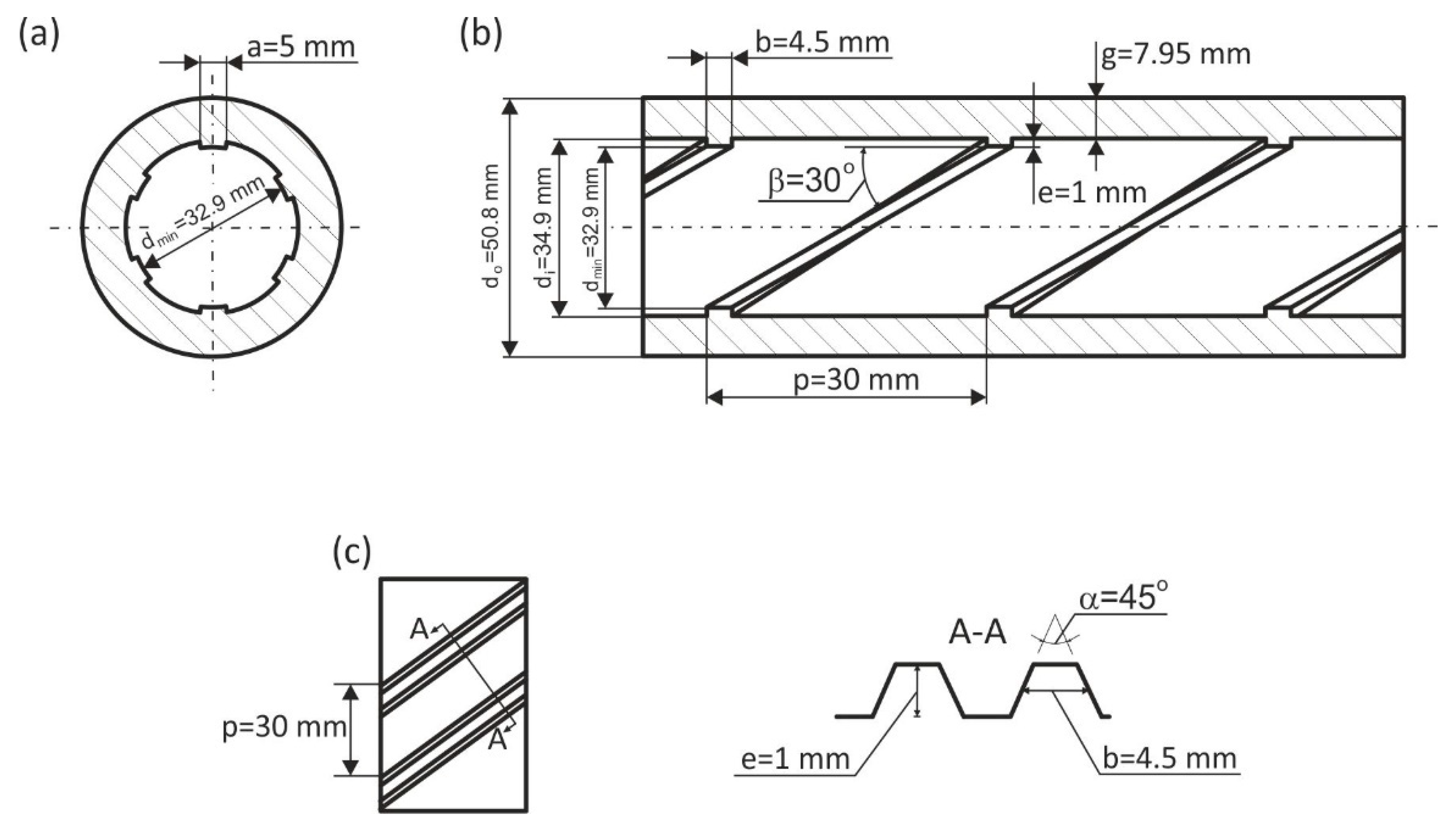
where: β = 30° and e/d
i = 1/34.9.
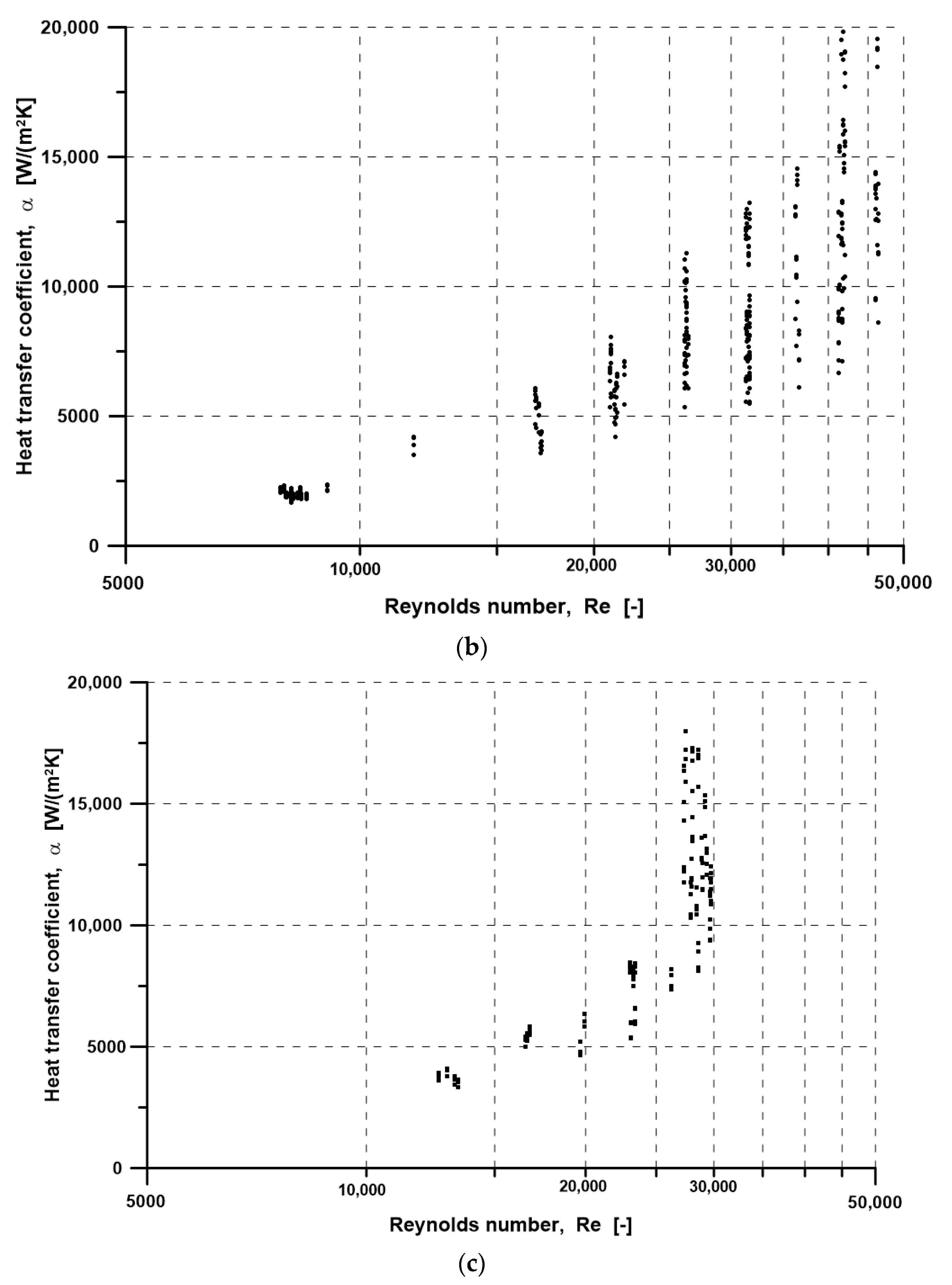
The diagrams in
Figure 4 show the results of the testing of the heat transfer coefficient as a function of the Reynolds number [
16] obtained during the tube heating using a 6 kW heater (
Figure 4a), a 7 kW heater (
Figure 4b) and an 8 kW heater (
Figure 4c).
The experimental results of the heat transfer coefficient values will be used in this paper for comparison with the results obtained from CFD modelling (cf.
Section 4).
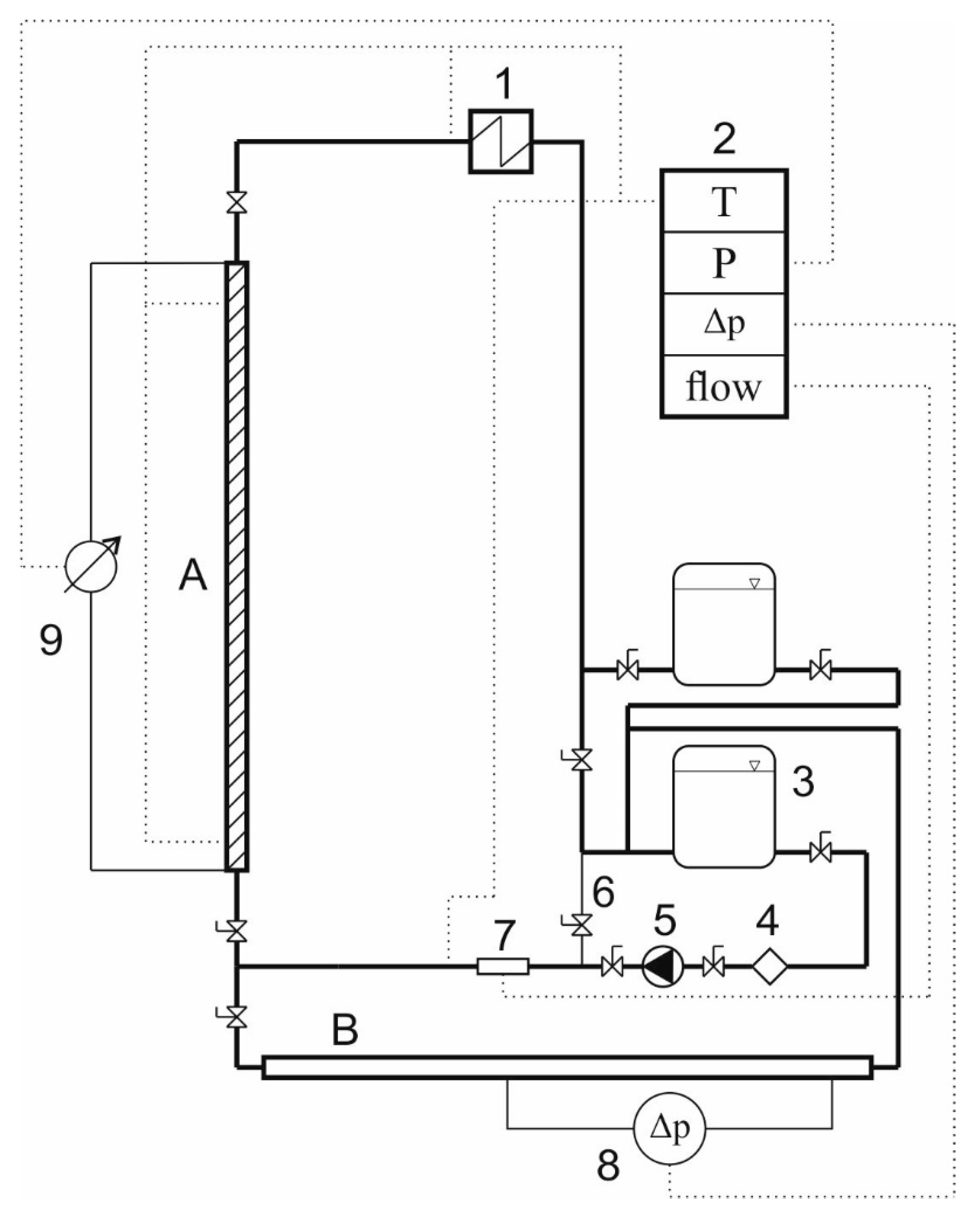
The experimental testing aiming to determine the friction factor was carried out on the horizontal section of the test stand presented in
Figure 1. The measurements were performed using a PXWD differential pressure transducer and a liquid U-tube. The research works, the applied measuring methods and the results are described in detail in [
12].
The obtained measuring data were used to determine the correlation for the friction factor calculation, which takes the following form:
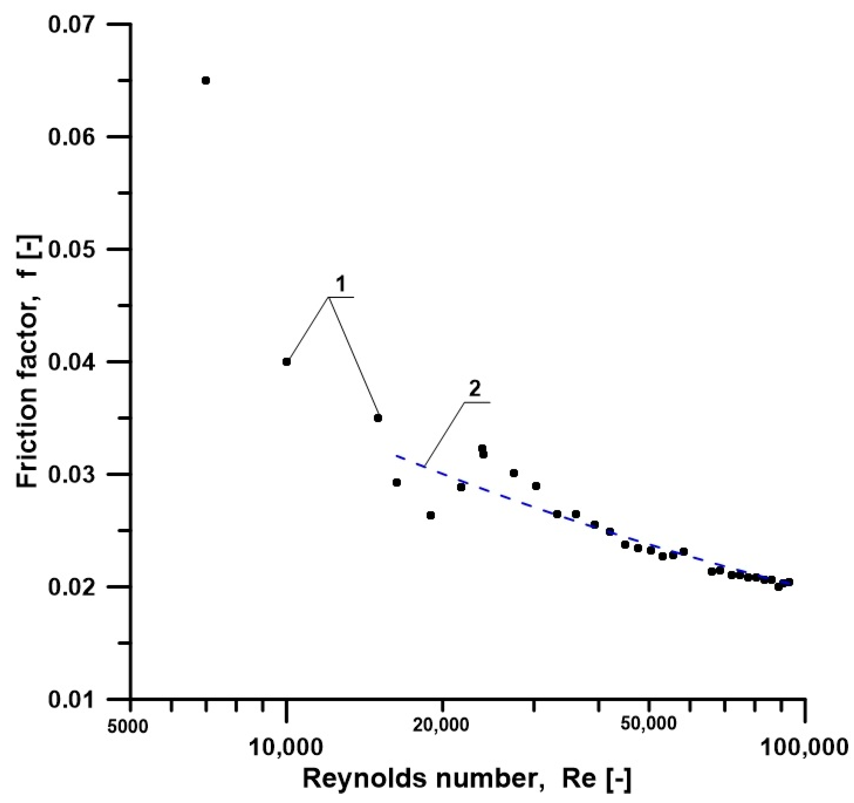
For the needs of the CFD modelling,
Figure 5 presents the experimental values of the friction factor and the results obtained from the developed Equation (6) compared to the results obtained for the smooth tube.
4. CFD Modelling
The heat transfer coefficient was modelled in steady state using CFD applications included in the ANSYS Workbench package [
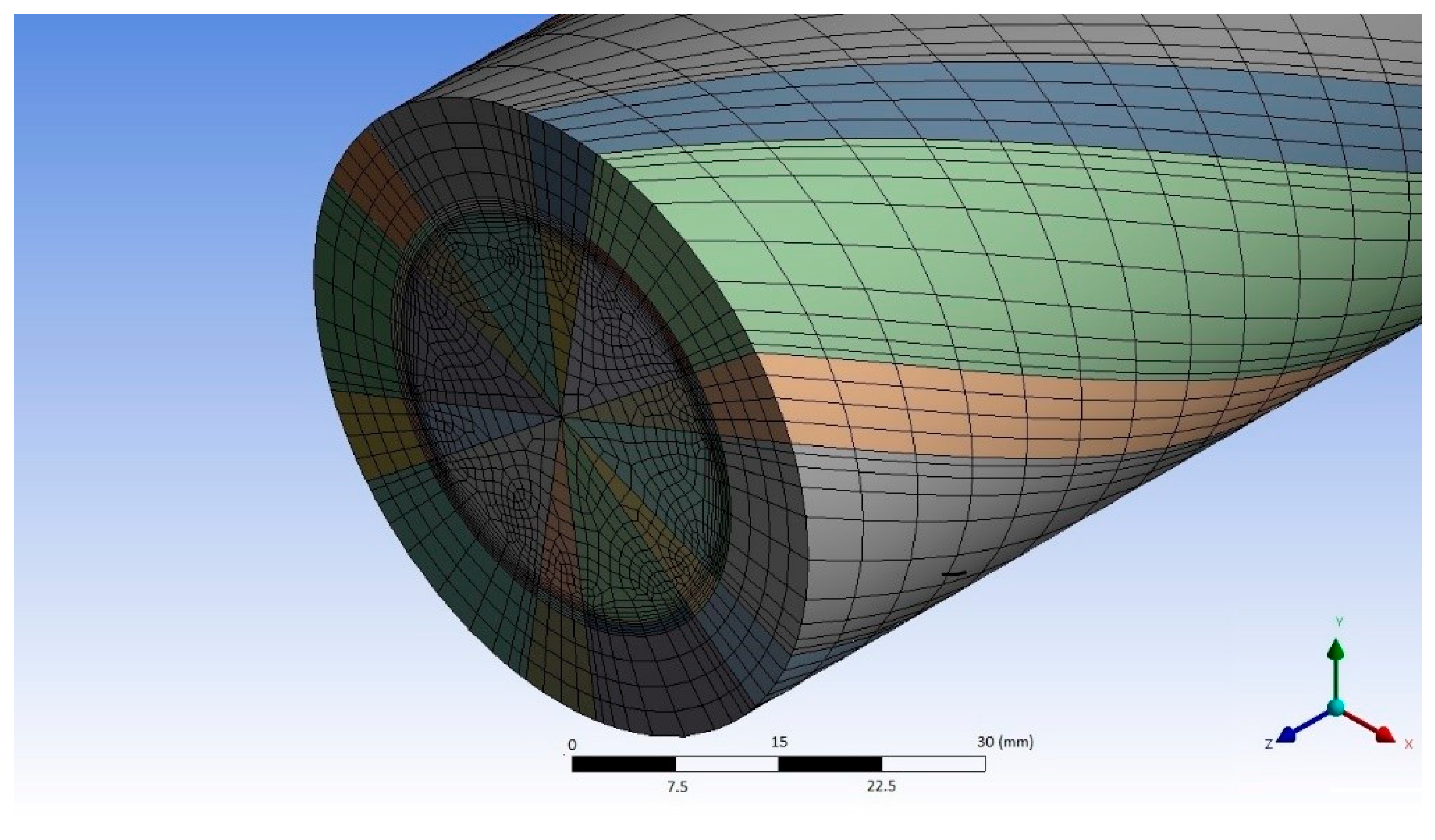
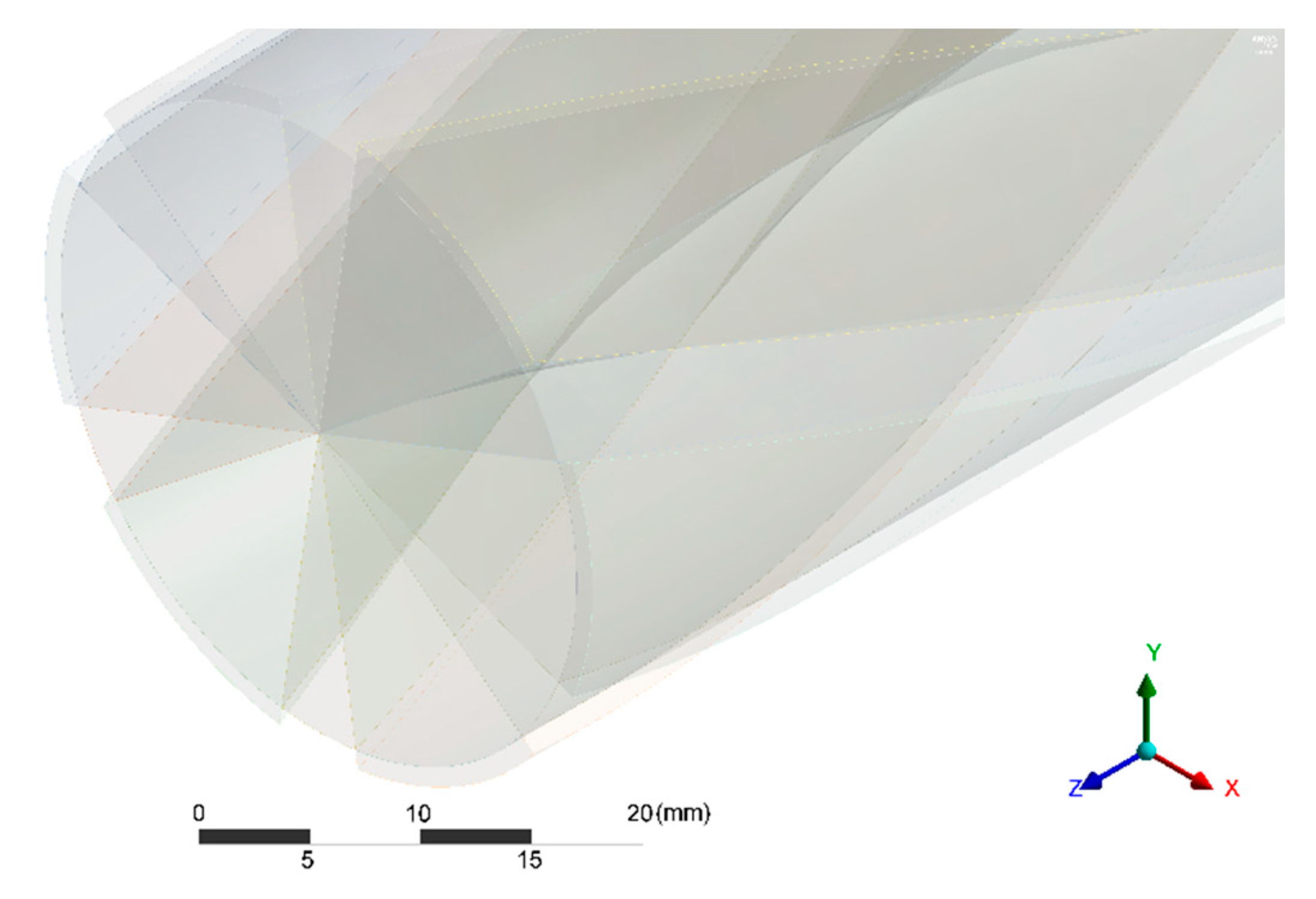
13]. The CFD calculations were performed based on a model with the mesh as shown in
Figure 6.
The key element in the mesh generation process is to increase the mesh density in the near-wall zones (in the boundary layer), where the highest gradients of the calculated values occur. Apart from that, a dense mesh in the zone between the ribs and close to them makes it possible to simulate the helical nature of the fluid flow. The wall is divided into four elements along its thickness to ensure better mapping of the temperature field irregularities caused by the presence of the ribs. Basic information on the meshes is presented in
Table 2.
The number of the model elements has an essential impact on the computation time and the use of the processor computing power. The computation process is affected considerably by the shape of the elements, their number, the location of nodes in adjacent elements, the ratio between the element’s longer and shorter edge, the helical angle, etc. Moreover, the correctness of the computational mesh generation process has an effect on the quality of results and potential numerical errors. Due to the applied method of the numerical mesh preparation, all the finite elements have six walls with the top and bottom bases slightly shifted in relation to each other. This is related to the ribs helix and the model division in relation to the helices. The effect is a curvature of the control volumes, which lengthens the computation time to a certain degree. The mesh used in the presented model was selected as optimal in terms of the calculation time after comparing it with other meshes analysed for internally rifled tubes with spiral ribs in [
24].
A very important aspect of CFD modelling is the selection of an appropriate turbulence model. The heat transfer coefficient was calculated using the k-ω, the k-ε, and the transition SST (Share Stress Transport) turbulence models.
The k-ω model is based on two equations, which means that two additional transport equations are used to represent turbulence-related phenomena. The first variable determines turbulent kinetic energy k, and the second variable determines the turbulence scale ω. The k-ω model should be used when large velocity and pressure gradients are expected.
The k-ε model is based on two equations, which determine turbulent kinetic energy k and degree of speed variation ε. Due to its flexibility, simplicity and adaptation to many considered cases, this model is very often used in engineering calculations, especially fully developed flows. The disadvantage of this model is its lower accuracy at flows with large pressure gradients.
The transition SST (Share Stress Transport) model is based on four equations, which determine turbulent kinetic energy k, degree of speed variation ε, transition and interruption. The model was developed to observe the phenomena occurring in the transition areas. The use of the model is limited to flows in the zone bounded by the wall-type condition. The model has not been verified during the modeling of phenomena related to buoyancy and multiphase flows.
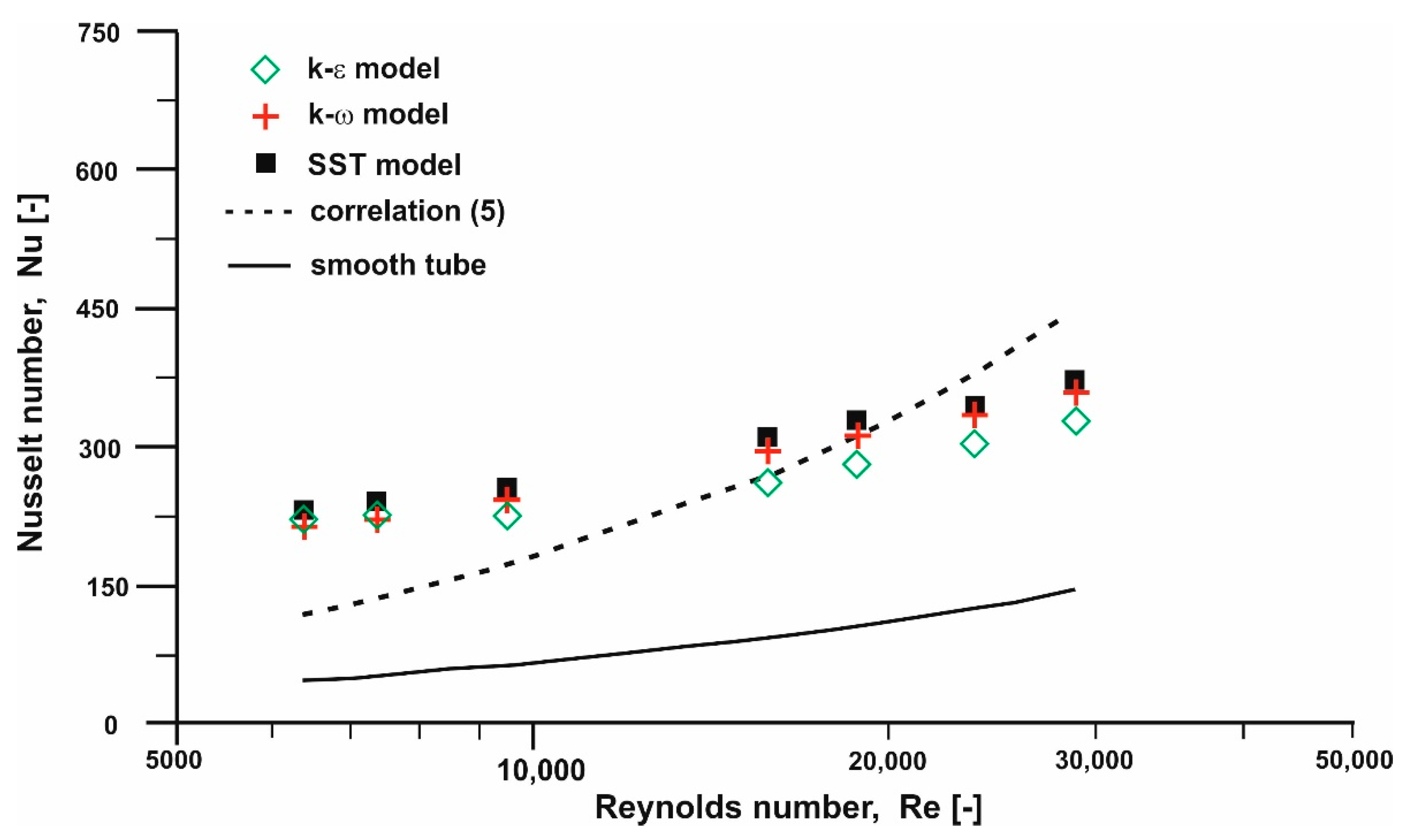
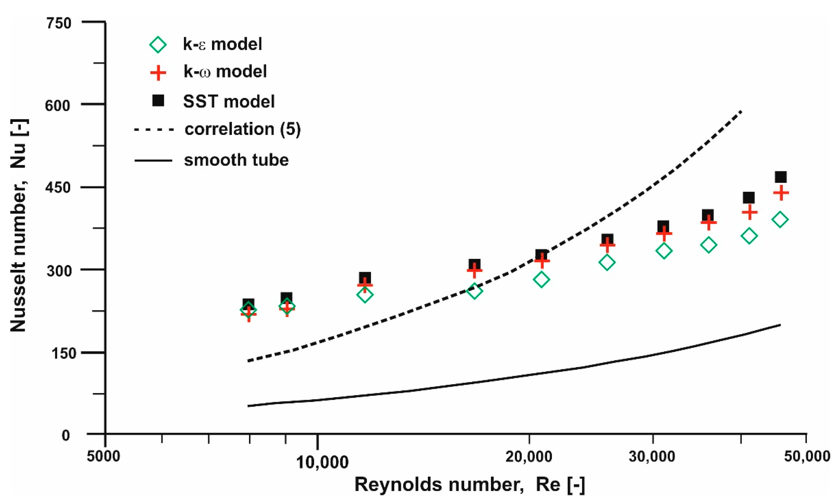
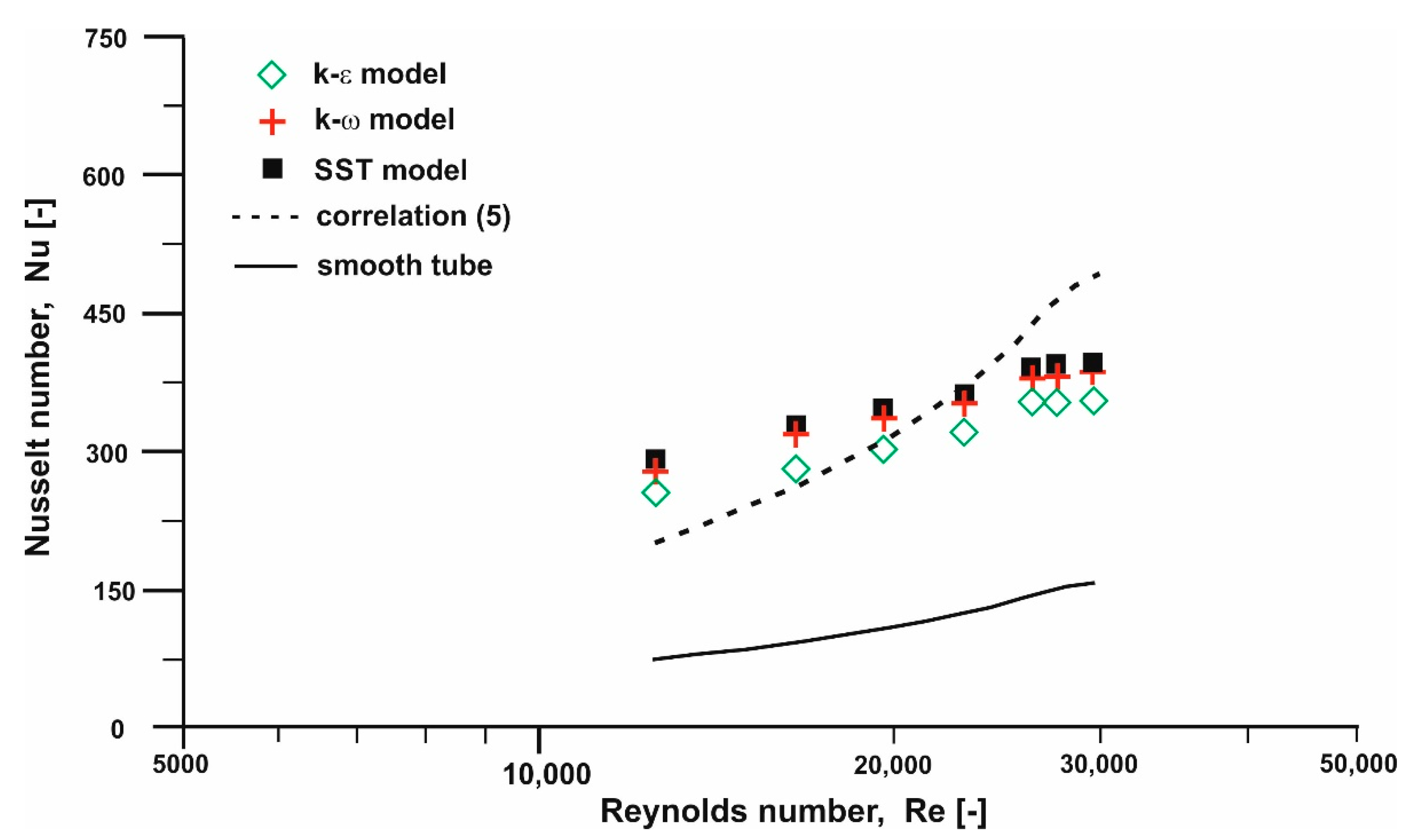
During the modelling the impact was investigated of the selected turbulence model on the obtained values of the heat transfer coefficient and the Nusselt number. The input parameters were selected from the values obtained from experimental testing. The heat transfer coefficient results obtained from the CFD modelling were used to select the values for the Nusselt number calculation. The Nusselt numbers were then compared to the values calculated for tubes with internal spiral ribs using the developed Equation (5). A comparison of the results is presented in
Figure 7,
Figure 8 and
Figure 9 for the power of the heater of about 6 kW, 7 kW and 8 kW, respectively. Additionally,
Figure 7,
Figure 8 and
Figure 9 show the curves illustrating changes in the Nusselt number calculated for a smooth tube. Analysing the figures, it can be noticed that the corresponding values of the Nusselt number for the smooth tube are much lower compared to the rifled tube.
Based on the figures presented above, it can be stated that the Nusselt numbers calculated for the k-ε, the k-ω and the transition SST model take very similar values. The similarity is due to the fact that the heat transfer mechanism is described using the same equations. Comparing the calculated values to the experimental results, convergence can be observed for Reynolds numbers included in the range from 17,000 to 22,000. In the case of smaller flows, CFD modelling produces values that are about twice higher compared to those measured during the experiment. If the Reynolds number exceeds 22,000, the Nusselt number obtained based on the measuring data reaches higher values compared to the CFD modelling results. The experimental testing results confirmed that a shift occurred as the flow changed its nature from transient to fully developed. The transitional region for rifled tubes occurs for Reynolds numbers from the range of 17,000–21,000 and is related to very big changes in the friction factor at slight changes in the values of the Reynolds number. This affects the distributions of the fluid parameters obtained using the applied turbulence models, and the heat transfer parameters in rifled tubes related to them. The discrepancy in the results is also an effect of random errors related to the measurement of small pressure drops at small mass flows of the medium. Analysing the CFD modelling results, it can be seen that an increase in the Reynolds number does not involve a high rise in the Nusselt number values, which are relatively low. Based on the CFD modelling of the thermal and flow phenomena in rifled tubes with internal spiral ribs, it can be observed that none of the applied models can simulate the convective heat transfer process in the full flow range under analysis.
In the case of the heat transfer coefficient in rifled tubes with internal spiral ribs, the quantity distribution in individual areas of the inner surface is very interesting, which is illustrated in
Figure 10. It can be seen clearly that the coefficient reaches the highest values in zones close to the rib tips. In the area in between the ribs, the quantity takes values by about 40% lower compared to the rib tip. In the case of the rib lateral edges, the heat transfer coefficient takes the lowest values, totalling about 40% of those for the rib tip.
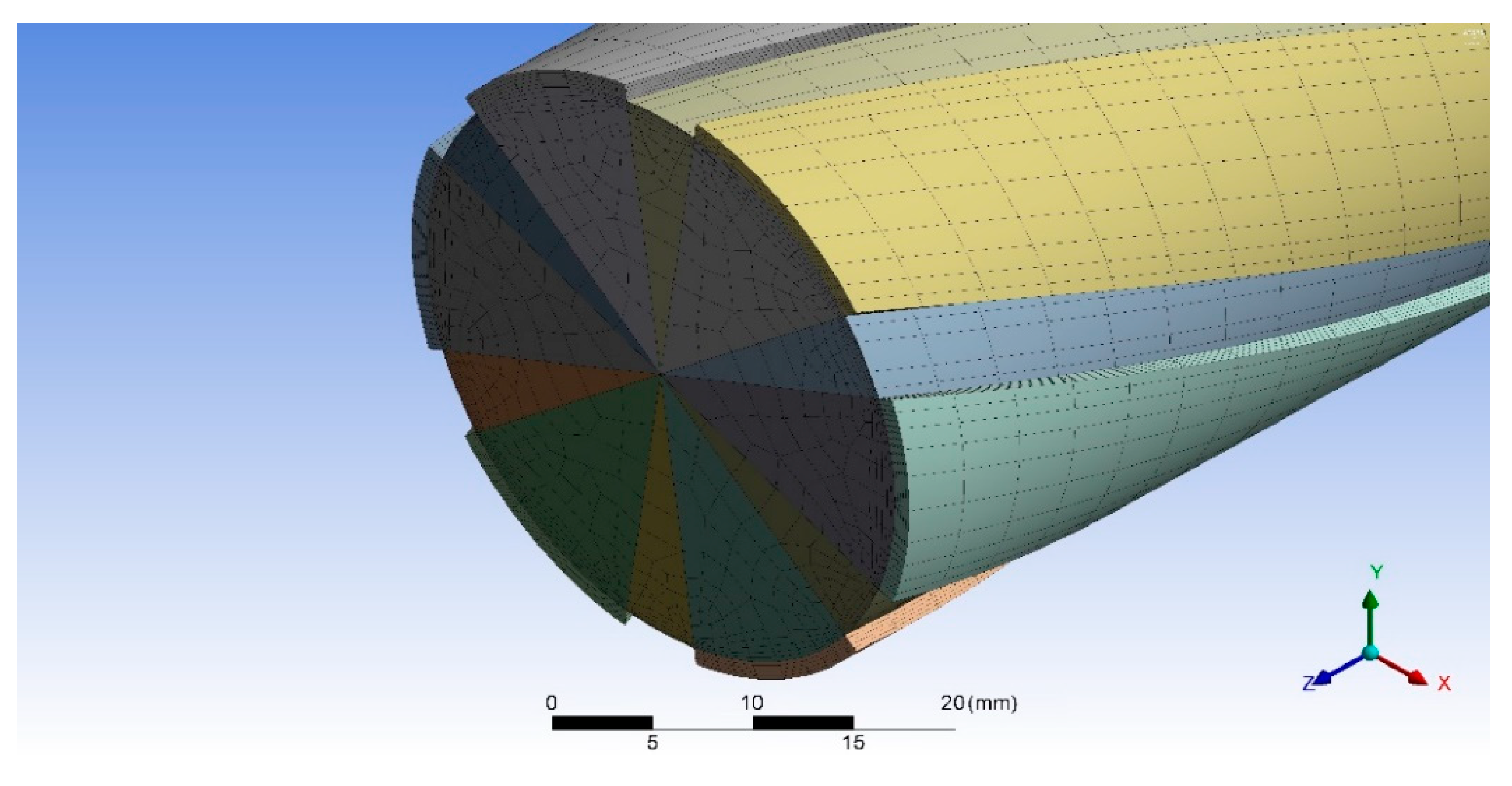
The pressure losses due to friction were modelled using the model presented in
Figure 11 and the mesh shown in
Figure 12.
The properties of the applied mesh are listed in
Table 3. The calculations were carried out for boundary conditions corresponding to the flow parameters used during the experimental testing. The mass fluxes of the flowing water and the Reynolds numbers corresponding to them are gathered in
Table 4. The simulations were performed using the Ansys Fluent program [
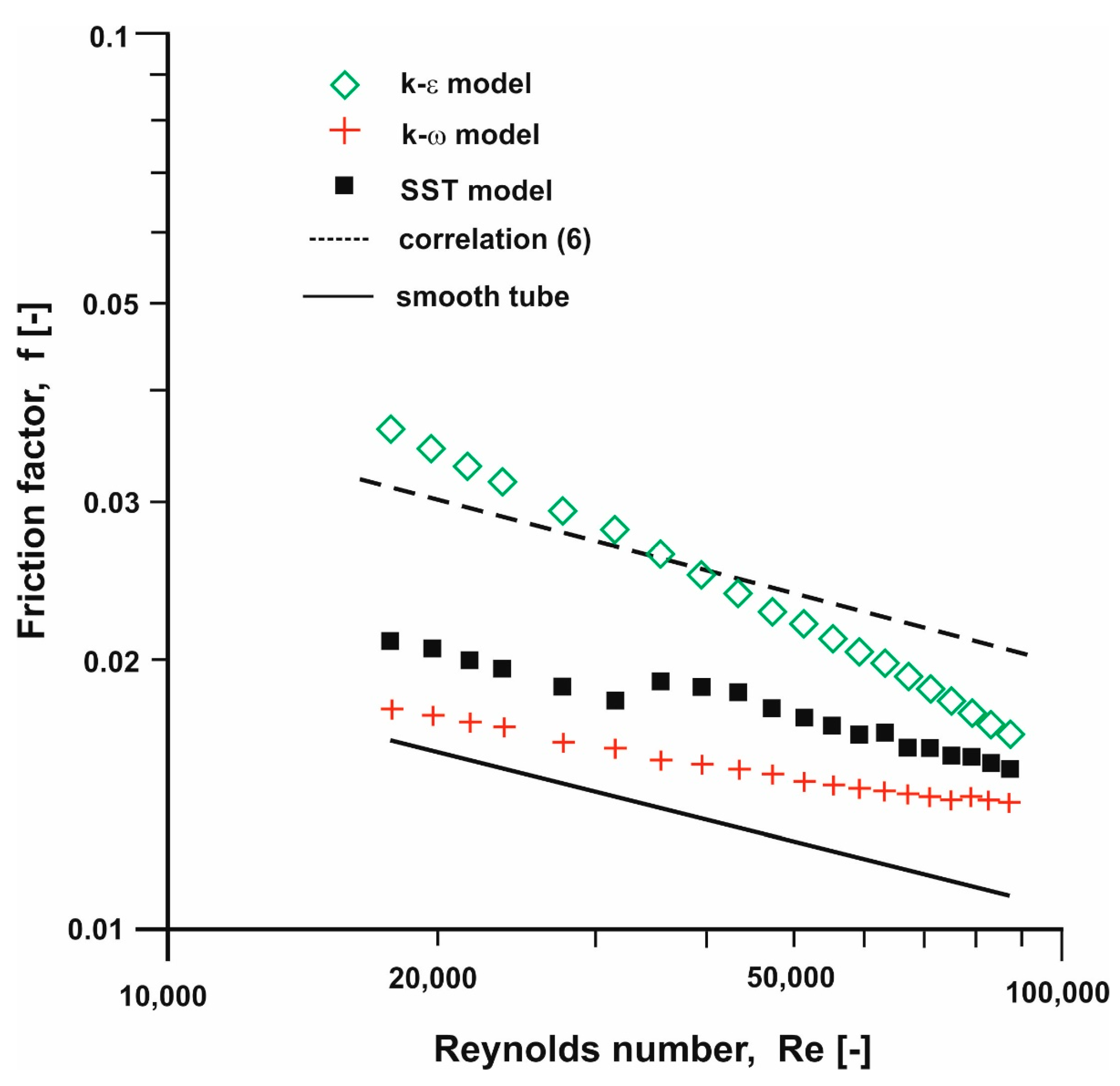
13]. The calculations were carried out using 3 standard turbulence models: the k-ω, the k-ε and the transition SST (Share Stress Transport). The modelling resulted in a pressure difference on a 1-m long tube section. The calculated pressure drops were used to determine the friction factor values. A comparison between the obtained values and those produced by correlation (6), compared to the results obtained for smooth tube, is presented in
Figure 13.
Comparing the values, it can be observed that none of the selected turbulence models can fully simulate the phenomena related to frictional losses. For Reynolds numbers Re < 30,000, the k-ε model results are close to the experimental data. However, the results from the three applied models demonstrate a downward trend. For Reynolds numbers Re > 50,000, none of the models under consideration can simulate the pressure losses in the flows through rifled tubes with internal spiral ribs. In the case of the k-ω and the transition SST model, which should perform well in the simulation of the boundary layer phenomena in the entire analysed range of Reynolds numbers, the friction factor takes very low values.
5. Conclusions
The paper presents an experimental determination of the heat transfer coefficient and the linear frictional losses in an internally rifled tube with spiral ribs. The testing was carried out on a laboratory stand constructed in the Department of Energy of the Cracow University of Technology. The data obtained from the measurements were used to validate the CFD computations performed using selected turbulence models. During preparatory works, it turned out that the model development and division into finite volumes needed a lot of effort. Using the presented numerical meshes, simulations were performed of thermal and flow phenomena occurring in an internally rifled tube.
Analysing the heat transfer modelling results, it can be concluded that the applied models made it possible to obtain values similar to those of the experiment only in a very narrow range of Reynolds numbers. In the case of Reynolds numbers lower than about 17,000, the turbulence models tend to inflate the heat transfer coefficient values, whereas, for the Reynolds numbers exceeding 22,000, all the turbulence models produce underestimated values. It can also be observed that with the increase in the value of the Reynolds number, there is no large increase in the value of the Nusselt number, and the obtained values are almost constant. Based on CFD modeling of heat-flow phenomena in an internally rifled tube with spiral ribs, it can be seen that none of the used models is able to fully reproduce the convective heat exchange process in the analysed range of flows.
In the case of modelling pressure losses, none of the applied models succeeded in simulating linear losses in the full range. The k-ε turbulence model performed well in the simulation of linear frictional losses for flows with Reynolds numbers smaller than 35,000. In the case of bigger flows, frictional pressure losses obtained from CFD modelling are very low. Moreover, the calculated values of the frictional factor are higher than the values obtained in smooth tubes. In the case of the k-ω and transient SST models, which should accurately reflect the phenomena occurring in the boundary layer in the entire analysed range of Reynolds number values, the coefficient of linear friction losses takes values close to that for smooth tubes only for low values of Reynolds number.


 ,
, 


