
Simulating Plasma Formation in Pores under Short Electric Pulses for Plasma Pulse Geo Drilling (PPGD)


1
Geothermal Energy and Geofluids Group, Institute of Geophysics, Department of Earth Sciences, ETH Zurich, 8092 Zurich, Switzerland
2
Department of Earth and Environmental Sciences, University of Minnesota, Minneapolis, MN 55455, USA
*
Authors to whom correspondence should be addressed.
Energies 2021, 14(16), 4717; https://doi.org/10.3390/en14164717
Submission received: 10 June 2021
/
Revised: 28 July 2021
/
Accepted: 29 July 2021
/
Published: 4 August 2021
(This article belongs to the Section H: Geo-Energy)
Abstract
:Plasma Pulse Geo Drilling (PPGD) is a contact-less drilling technique, where an electric discharge across a rock sample causes the rock to fracture. Experimental results have shown PPGD drilling operations are successful if certain electrode spacings, pulse voltages, and pulse rise times are given. However, the underlying physics of the electric breakdown within the rock, which cause damage in the process, are still poorly understood. This study presents a novel methodology to numerically study plasma generation for electric pulses between 200 and 500 kV in rock pores with a width between 10 and 100 μm. We further investigate whether the pressure increase, induced by the plasma generation, is sufficient to cause rock fracturing, which is indicative of the onset of drilling success. We find that rock fracturing occurs in simulations with a 100 μm pore size and an imposed pulse voltage of approximately 400 kV. Furthermore, pulses with voltages lower than 400 kV induce damage near the electrodes, which expands from pulse to pulse, and eventually, rock fracturing occurs. Additionally, we find that the likelihood for fracturing increases with increasing pore voltage drop, which increases with pore size, electric pulse voltage, and rock effective relative permittivity while being inversely proportional to the rock porosity and pulse rise time.
1. Introduction
The cost of deep drilling contributes significantly to the feasibility of economically accessing deep geo-energy resources (i.e., geothermal, oil, and gas) as drilling costs make up the majority of overall project costs [1]. Several studies have employed the artificial neural network approach to enhance the performance of mechanical rotary drilling by predicting the lithology [2], the mud apparent viscosity [3], and the penetration rate [4]. However, mechanical rotary drilling costs are high and increase exponentially with depth as rotary drilling relies on mechanical abrasion [5]. Therefore, the economic extraction of geothermal energy requires developing cheap and fast drilling methods such as Plasma Pulse Geo Drilling (PPGD) and thermal spallation [5,6,7].
Plasma Pulse Geo Drilling (PPGD) is a novel contactless drilling technology, which uses high-voltage electric pulses to break away the rock, without relying on mechanical abrasion (e.g., [5,8,9,10,11,12,13,14,15,16,17,18,19]). Thus, PPGD is part of a class of new “contactless” drilling technologies, which also includes thermal spallation (e.g., [6,20,21,22,23,24,25,26,27,28,29,30,31,32]) and water jet drilling (e.g., [33,34,35,36,37]) and laser drilling (e.g., [38,39,40,41,42,43]) to name only some. PPGD has been given various names in the literature, including Electropulse Drilling, Plasma Channel Drilling, and Electric Impulse Drilling.
Several studies have shown that PPGD has lower costs than rotary drilling, as the absence of mechanical abrasion increases the bit lifetime and decreases the number of tripping cycles, thereby reducing drilling costs. Experimentally, Anders et al. [13] found PPGD to be up to 17% cheaper and seven times faster than mechanical rotary drilling. Analytically, Rodland [44] and Schiegg et al. [5] suggested that further research could possibly reduce PPGD drilling costs by 90% or more of current mechanical rotary drilling costs. Therefore, once developed, PPGD may replace conventional mechanical rotary drilling in a number of fields, such as geothermal energy extraction.
To understand how PPGD operates, it is necessary to understand the terms “plasma” and “electric breakdown” and to clarify the difference between them. The plasma state is the fourth state of matter, which is a quasi-neutral, electrically conducting gas of ions and electrons that exhibit collective behavior [45]. A plasma occurs when the dielectric material (i.e., gas, liquid, or solid) experiences a voltage that exceeds a certain threshold, the so-called breakdown voltage [45,46,47]. Once the plasma forms, the material loses its insulating properties and becomes an electrical conductor. Consequently, a strong electric current passes through the formed plasma, causing a drop in the voltage difference across the plasma, termed electric breakdown. Gas and liquid dielectric materials usually recover their insulating properties once the voltage is turned off. A solid dielectric, however, usually experiences permanent damage.
In PPGD, an electric pulse between about 200 and 500 kV is applied across a rock sample to cause the rock to fracture. Typically, when such a high voltage discharge occurs on a rock surface, the electric breakdown occurs in the fluid connecting the two electrodes (i.e., the drilling fluid), because the fluid has a higher electrical conductivity than the rock [8,10,11,16,19]. This higher electrical conductivity is caused by conducting-impurities in non-synthetic fluids (e.g., water). However, Vorob’ev et al. [8] (translated by Boev et al. [9]) observed that electric breakdown occurs in the rock, instead of the fluid, when the electric pulse rise time is less than half a microsecond (<500 ns, 1 ns = 10 s), as the response time of conducting-impurities in the fluid is significantly slower than the pulse rise time. The impurities effect is therefore negligible for short rise times, and the fluid electrical conductivity becomes lower than the rock electrical conductivity under these circumstances. Electric breakdown can thus be directed to occur within the rock and its fluid-filled pores, which can result in rock fracturing. However, the underlying physics of the electric breakdown within the rock are poorly understood, as the experimental investigations of rock fragmentation under high electric voltages in a solid material are highly complex, and the associated time and spatial scales are very small. Unfortunately, this lack of understanding of the process further complicates the optimization of PPGD tools and limits their range of applicability.
Several experimental studies have investigated the mechanisms underlying the electric breakdown of solid materials and specifically the electric breakdown of rock using PPGD-type methods. These studies have observed three different mechanisms, which are the “partial discharge breakdown”, the “electrical treeing breakdown”, and the “thermal breakdown”, which are different as we discuss briefly next [10,11,16,17,19,46,48,49,50].
In “Partial Discharge Breakdown”, the electric breakdown occurs in single rock pores, leading to high pore pressures and, consequently, rock fracturing [10,47]. Lisitsyn et al. [10] also observed that damage occurred in dried granite samples, while no damage occurred in water-saturated granite samples. Conversely, Timoshkin et al. [11] later found damage to occur within a brine-saturated rock. However, the penetration rate in the brine-saturated samples was 35% lower than that in the dried samples.
While “Partial Discharge Breakdown” occurs in single pores, the formation of breakdown channels along the whole path between the electrodes through a solid material is called “Electrical Treeing Breakdown” [49]. Here, hollow discharge tubes, resembling the branches of trees, are formed due to electrical stresses. The trees start at the high voltage electrode because of the high concentration of the electric field. The trees form either by converting regions of the solid of high electric field concentration into gas and ultimately into plasma or by converting pore content (i.e., air) into plasma (i.e., by the occurrence of the Partial Discharge Breakdown in pores). After a few voltage impulses, these small trees grow toward the grounded electrode, forming a gaseous channel between the two electrodes, in which a plasma-channel occurs (i.e., the breakdown takes place). Once electric breakdown occurs, the material has failed from the perspective of electrical engineering, and does not function as an insulator anymore. This does not, however, indicate mechanical failure, which is crucial for drilling success, and has to be determined separately, for example with a mechanical failure criterion. Mechanical failure could occur due to a single electric breakdown or after multiple consecutive electric breakdown cycles.
Once an electric field is established and electric current flows through the rock, the electric resistance results in heat dissipation into the rock, which can be described by the “Thermal Breakdown” mechanism [17,46,50]. Here, thermomechanical fracturing of the rock occurs due to uneven heating by the applied electric voltage, which causes uneven temperature distributions and thus induces internal stresses. These thermal stresses can lead to thermal strain and rock failure, which present a different failure mechanism than the increased pore pressures caused by Partial Discharge Breakdown and Electric Treeing Breakdown. Ultimately, all three mechanisms can contribute to the fracturing of rock during PPGD.
Despite numerous experimental studies, little work has been performed on simulating the underlying pore-scale physics during the electric breakdown of the rock. Li et al. [15] studied the “Electrical Treeing Breakdown” approach by modeling the plasma formation in long fractures connecting the electrodes. Failure of the surrounding rock was modeled by propagating the channel pressure into the rock to determine if the induced stresses lead to fracturing. Although the resultant pressure was shown to be sufficient to induce fracturing, it is unclear if the underlying assumptions can be applied to the PPGD process, as the authors used the coefficients for shock wave propagation in water to describe wave propagation in granite rocks. The authors further used a simulation time of 500 μs, while the PPGD process occurs on the timescale of less than 5 μs. By using a much larger simulation time, the calculated injected energy into the plasma channel is larger than what can be assumed for PPGD, thereby causing higher plasma-channel pressures.
Conversely, Walsh and Vogler [50] and Vogler et al. [17] simulated the “Thermal Breakdown” mechanism, whereby the electric discharge provides ohmic heating within the rock, and found that ohmic heating can be sufficient to induce rock fracturing. Vogler et al. [17] also found that the fragmentation volume increases with salinity, which could explain why Lisitsyn et al. [10] observed no damage in their water-saturated rock samples, while Timoshkin et al. [11] observed damage in their brine-saturated rock samples.
Numerically, Zhu et al. [19] used the dielectric breakdown condition to investigate whether the partial discharge occurs at the pore scale. Zhu et al. [19] assumed that the partial discharge breakdown induces local damage at the microscale without calculating the induced local stresses. In contrast, in this paper, we study the “Partial Discharge Breakdown” mechanism by modeling the plasma formation in rock pores to determine whether the resulting pore pressure is sufficient to fracture granite. This work aims at providing further insights into the Partial Discharge Breakdown mechanism, which has only been studied experimentally so far. Also, this study investigates the impact of pore size, maximum pulse voltage drop, and pulse rise time on plasma formation and the resultant pore pressure.
2. Model Description
To determine drilling success (i.e., rock damage) from our simulations, we hypothesize that the imposed voltage pulse on the rock induces a voltage gradient across the Nitrogen-filled rock pores. This voltage gradient generates a plasma, increases the pore pressure, imposes stresses beyond the tensile strength of rock, and ultimately results in the fracturing of the granite. Experimental studies have demonstrated the significant impact of three different parameters on rock damage during PPGD: (1) the maximum pulse voltage drop, , (2) the voltage pulse rise time, , and (3) the rock pore size, [10,13,48,51]. Therefore, our numerical simulations are conducted on granite pores with pore sizes between 10 and 100 μm, electric pulses from 200 to 500 kV, and voltage rise times from 30 to 300 ns.
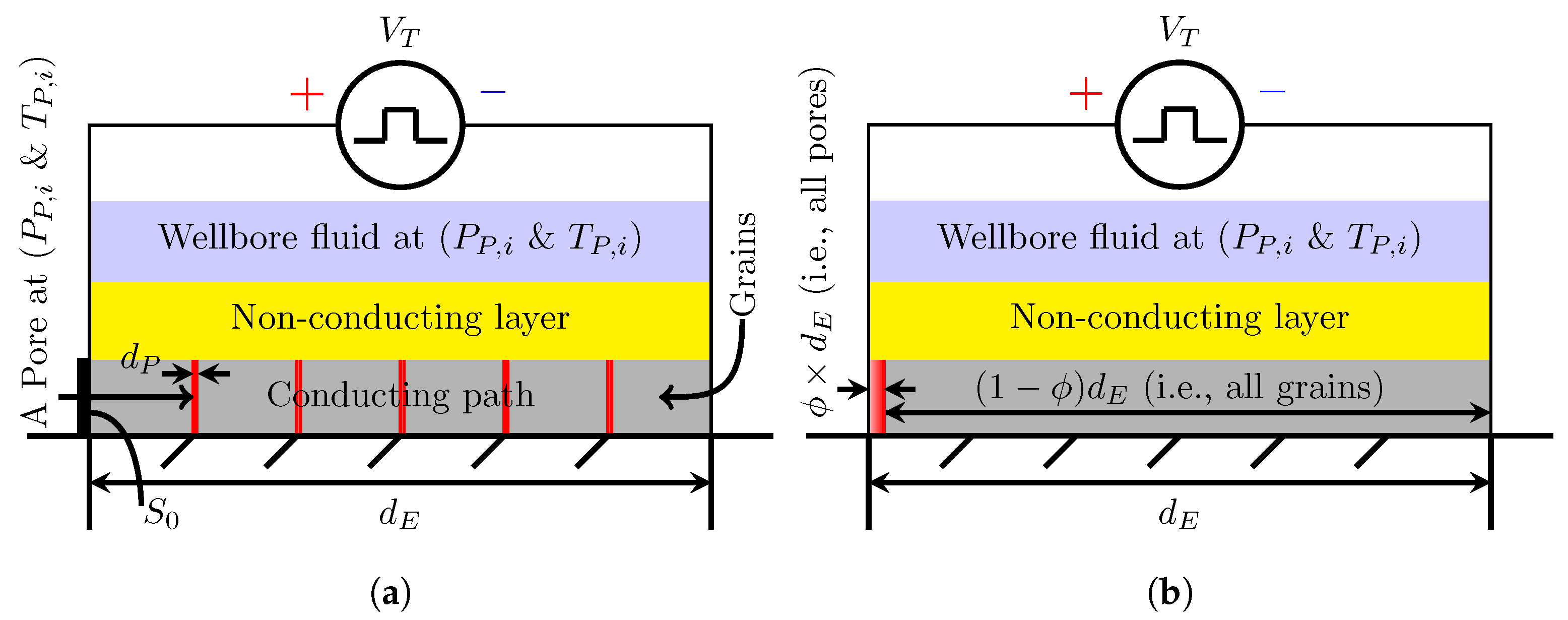
In an experiment, Lisitsyn et al. [10] placed two parallel electrodes on top of the sample, inducing a damage path between these two electrodes, replicating realistic drilling configurations. Figure 1a shows a one-dimensional adaptation of the path of the electric current between the two electrodes through the rock mass. This is the so-called conducting path, where the material damage occurs. This conducting path is comprised of alternating pores and grains, equally spaced along the sample length, , with the typical granite pore sizes, . Figure 1b, however, shows the total pore space and the total rock mass as one connected phase to be used in the capacitor model introduced in Section 2.2.2. Even though the pulse voltage, , is imposed across the entire rock sample, we assume that the electrical current only flows axially through the cross-sectional area of the conducting grain and pore composite, , neglecting any current flow through the non-conducting layer and the wellbore fluid. Thus, one can assume that the electric current flows through the pores along the shortest path from one rock wall to the other, similar to current flow in a capacitor with two parallel plates. When simulating the resulting pore pressure in individual pores, we describe the electric boundary conditions on the rock walls, which form the boundary between the pore and the solid. We assume that the pores are Nitrogen-filled with a pressure, , that equals the adjacent wellbore fluid pressure.
To simulate rock fracturing due to plasma formation, invoking the Partial Discharge Breakdown mechanism, we make the following assumptions:
- The electric current is confined to a single, 1-D conducting path of rock grains and rock pores, similar to previous experimental studies [10,48]. Here, we assume that the voltage pulse dissipates all its energy into the simulated conducting path, and we neglect the electric energy dissipation in the non-conducting layers and the wellbore fluid.
- All energy dissipated from the electrodes into the conducting path either (a) generates a plasma within the rock pores or (b) heats the rock grains. However, we only investigate the energy dissipation into pores for generating and heating the plasma, resulting in the final pore pressure. Thus, we neglect all effects induced by thermal stresses that occur due to heating of the rock grains.
- All energy dissipated into the rock pore fluid (i.e., Nitrogen) heats the pore fluid as an ideal gas at constant volume, increasing the pore fluid pressure. We thereby neglect the variation of the gas specific heat capacity with temperature.
With the above assumptions, we can model plasma formation in pores with the aim of calculating the final pore pressure and subsequent rock fracturing mechanism, employing the following steps:
- First, realistic operation parameters for the simulation are selected (Section 2.1).
- The voltage drop across the simulation domain (i.e., a single pore) is calculated with the pulse voltage distribution law (Section 2.2).
- The Nitrogen Paschen Curve, which defines the minimum voltage for plasma formation for a given pore size and initial pressure, is then compared with the pore voltage drops calculated by our model. This can determine if plasma formation can occur (Section 2.3).
- Next, the voltage drop across the pore is used to simulate plasma generation in each rock pore. Here, BOLSIG+ [52] and ZAPDOS [53] determine the power deposition density within a pore, which is defined as the electric energy deposition per unit time per unit volume (Section 2.4 and Section 2.5).
- The increase in gas pressure can then be calculated from the power deposition density of the plasma electrons to the surrounding pore plasma ions (Section 2.6).
- Lastly, a damage model is used to determine whether the resulting pressure will result in rock fracturing (Section 2.7).
The six steps of the methodology are described in more detail in Section 2.1, Section 2.2, Section 2.3, Section 2.4, Section 2.5, Section 2.6 and Section 2.7.
2.1. Simulation Parameters
The modeling parameters used in this study including the initial conditions are listed in Table 1, with the nomenclature given in Nomenclature. We post-process these parameters in Table 1 to calculate the input parameters of the plasma formation simulation (Section 2.5). Next, we justify the chosen values of each modeling parameter using the literature and a few valid assumptions.
This work simulates plasma formation in dry, Nitrogen-filled pores, as dry rock mass has dry pores that are filled with air or other gases. Dry pores can even occur in largely liquid-saturated rock masses, namely when isolated pores exist, as saturation-liquid only fills the connected pores, whereas the initial gas (e.g., air), that was present during the rock formation, may still occupy the isolated pores ([48] and the references therein). Simulating plasma formation in air-filled pores requires knowledge of all transport and the Townsend coefficients for electrons in air compositions, namely Oxygen, Nitrogen, and Hydrogen, which primarily depend on the electron-ion mass ratio (Section 2.4 elaborates on these coefficients). As Oxygen and Nitrogen constitute more than 98% of the air composition and the difference in the Oxygen and Nitrogen molecular weights is only 3%, we use Nitrogen as an alternative for air as the pore fluid to simplify the calculation without neglecting important physics principles.
The initial pore pressure and temperature are also required to perform plasma simulations. As we study granite under ambient atmospheric conditions, these conditions are used for the initial rock pore pressure, , and temperature, .
Lisitsyn et al. [10], Inoue et al. [48], and Vazhov et al. [12] studied experimentally granite damage under maximum pulse voltage drop, , ranging from 200 kV to 500 kV. This voltage range usually captures both successful and unsuccessful rock fragmentation conditions. Thus, we choose 200 kV, 300 kV, 400 kV, and 500 kV, for the maximum pulse voltage drop across the entire sample, .
Vazhov et al. [12] observed that the rock’s breakdown voltage increases with the electrode gap distance. Conversely, studies in Ushakov et al. [14] (Section 5.4) reported that the fragmentation specific energy (energy per rock volume) decreases with electrode gap distance. We therefore select a moderate 20 mm electrode gap distance ( mm), which is the electrode gap distance necessary to fracture granite with a 270 kV pulse voltage, according to Vazhov et al. [12].
As mentioned in the introduction, Vorob’ev et al. [8] (translated by Boev et al. [9]) found that a voltage rise time of less than 500 ns is required to ensure plasma formation in the rock, and not in the wellbore fluid. We therefore investigate voltage rise times, , of 30 ns, 100 ns, and 300 ns.
Granite was chosen for this study as drilling through hard rock is commonly required in several PPGD applications, such as deep geothermal drilling and deep-borehole disposal of nuclear waste ([17] and the references therein). Furthermore, several previous studies investigated PPGD in granite [10,15,17].
As we show in Section 2.2, knowledge of the relative electric permittivity, the porosity of the rock, and the pore size is necessary to calculate the voltage difference across one pore, which is required to perform the plasma simulation in the pore. Thus, we use a mixing rule to compute the effective relative electric permittivity for a homogeneous grain composition in granite, resulting in 5.58 (Section 2.2.3). We assume a rock porosity of = 1%, which is an average value for granite [54]. We use a typical pore sizes for granite of <100 μm to estimate the gap distance in the pores across which a plasma forms [55]. We select three values for the rock pore size, , of 10, 50, and 100 μm to be able to investigate the impact of the pore size on the final pore pressure.
We use a combination of the parameters shown in Table 1 to simulate the increase in pore fluid pressure during plasma formation. Then, we calculate the final pore pressure, , which is used in the damage model to evaluate whether it is sufficient to induce rock fracturing.
2.2. Voltage across a Pore
The parameters in Table 1 serve as a rock pore proxy for granite in which we can model plasma formation. Our model calculates the pore electric voltage as a function of time employing the following steps: (1) Select a pulse function that represents the voltage pulse profile (Section 2.2.1); (2) Determine how the voltage pulse is distributed among pores and grains using a capacitance circuit model (Section 2.2.2); and (3) Calculate the grains’ effective relative permittivity, which is necessary for the capacitance circuit model (Section 2.2.3).
2.2.1. Voltage Pulse Profile
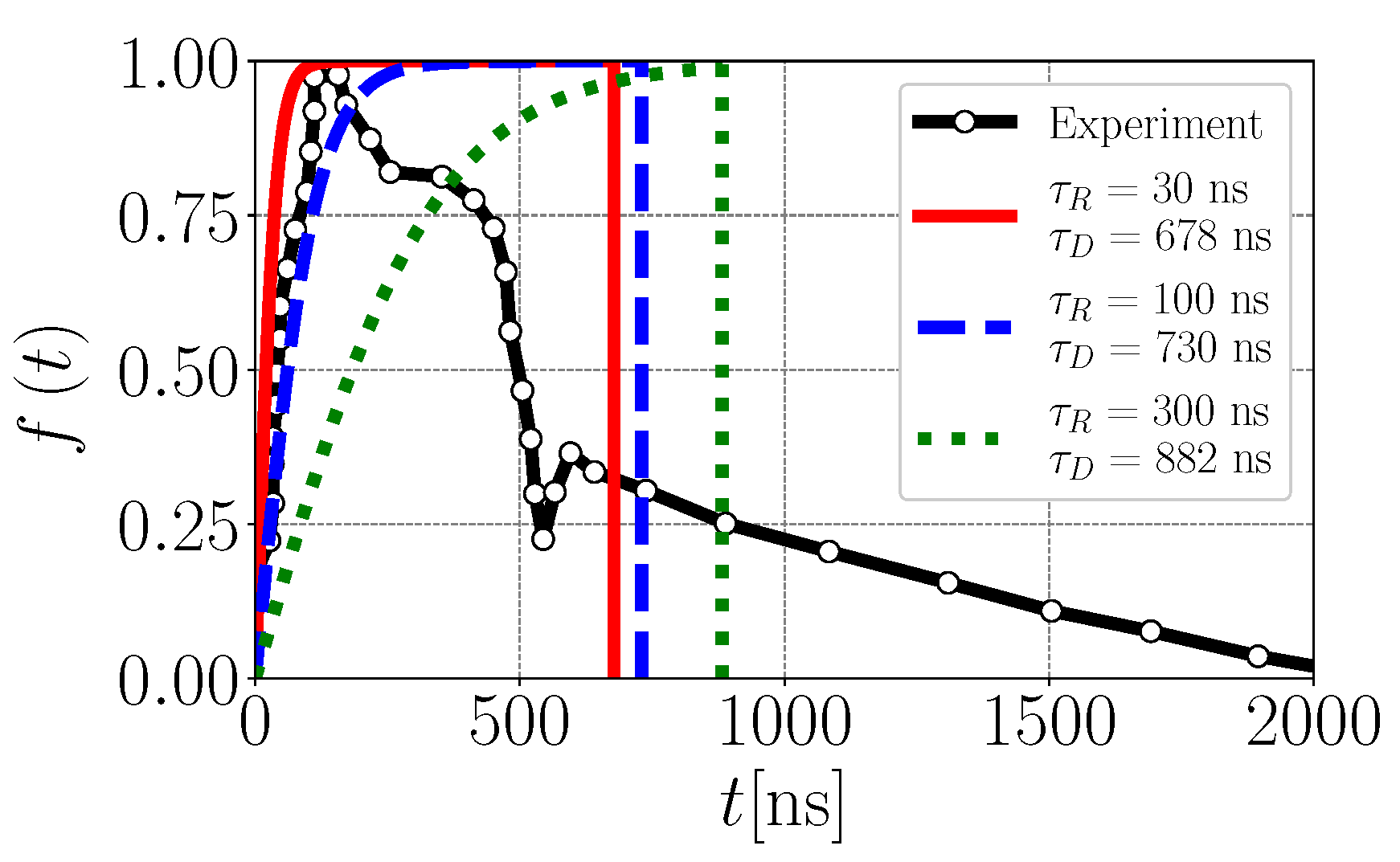
The electric pulse profile is crucial for PPGD, where not only the pulse rise time must be less than 500 ns ([8], as translated by Boev et al. [9]), but the pulse shape also determines the dissipated energy [56]. Thus, we use a typical normalized voltage pulse profile from the experimental study by Lisitsyn et al. [10], which is shown in Figure 2 (black line) to reproduce the pulse profile for the simulation as follows:
where is the voltage rise time and is the maximum voltage drop of the pulse. Figure 2 shows the three normalized voltage pulse profiles for the three rise times employed, with the values = 30 (solid red line), 100 (dashed blue line), and 300 (dotted green line). These profiles are set to zero after the corresponding discharge times (i.e., = 678, 730, and 882 ) have elapsed. The discharge time varies as a function of rise time, such that the areas under the experimental and the simulation pulse profiles are identical. This approach enables investigating the pulse rise time effect on the final pore pressure regardless of the maximum drop in pulse voltage. In addition to the voltage pulse profile, the voltage drop across a pore is required to simulate plasma formation.
2.2.2. Capacitance Circuit Model
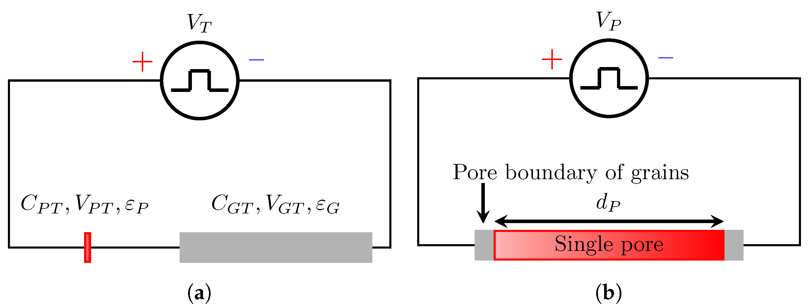
To determine the voltage drop across one pore, we use a one-dimensional model that consists of a series of rock pores and rock grains that connect the two electrodes (the conducting path in Figure 1a), where we treat the rock pores and rock grains as series-connected capacitors. As such, Kirchhoff’s voltage law applies, and the voltage change across the pores and rocks may be combined into two units: a single rock pore of length (), and a single rock grain of length , as shown in Figure 1b. The equivalent electric circuit of this approach (Figure 1b) is shown in Figure 3a, while we use in Section 2.5 a single pore as the plasma simulation domain (Figure 3b).
The equivalent circuit consists of the following two capacitors: (1) The first capacitor (in red) represents the single rock pore of capacitance, , voltage, , and effective relative permittivity, ; and (2) The second capacitor (in gray) represents the single rock grain of capacitance, , voltage, , and effective relative permittivity, . The sum of the voltage drops across the single rock grain, , and the single rock pore, , is the pulse voltage drop, , given in Equation (3):
According to Kirchhoff’s law, the ratio of the voltage drops of all rock grains, , and the overall circuit, , is equal to the inverse of the ratio of the total rock grains capacitance, , and the overall circuit capacitance, , shown in Equation (4). The same relationship holds for the total pore voltage drop, , and the total pore capacitance, , shown in Equation (5).
The single rock grain and the single rock pore are therefore connected in series as capacitors. Thus, the equivalent capacitance of the circuit, , is given by Equation (6):
Generally, a capacitor is defined as two parallel plates of surface area, S, separated by a distance, L. The capacitance, C, of a capacitor is the product of the electric permittivity, , and surface area, S, divided by the distance between the plates, L, given as a general formula in Equation (7). The electric permittivity is the product of the vacuum electric permittivity constant, = F/m, and the electric relative permittivity of the material, enclosed between the capacitor plates (i.e., rock grains or Nitrogen for rock pores), .
As we represent the rock pores and the rock grains as two single large capacitors, we compute the capacitance of each single large capacitor by substituting the corresponding distance and electric permittivity values in Equation (7). As defined, the two capacitors have the same cross-sectional area, , while the length of the grains’ single large capacitor is and the length of the pores’ single large capacitor is . Thus, the total capacitance of the rock grains, , and the total capacitance of the rock pores, , can be calculated using Equations (8) and (9), respectively:
The voltage drop across the single rock pore (i.e., all rock pores), , is solved for by combining Equations (5), (6), (8) and (9), resulting in Equation (10).
It is worth noting that this combination eliminates the vacuum permittivity constant from the pore voltage drop formula. Furthermore, we substituted the relative electric permittivity of the pore fluid (i.e., Nitrogen) by = 1, obtained from Uhlig and Keyes [57].
For ease of calculation, we combine the rock pores into a single element and solve for the voltage drop across all pores, . This combination is possible because we assume that all pores have the same pore fluid (i.e., Nitrogen) and thus the same electric permittivity. Consequently, the voltage distribution depends linearly on the pore size. To find the voltage drop across a single pore, , we must divide the voltage drop across all pores, , by the number of pores between the two electrodes, , given in Equations (11) and (12).
The number of rock pores is the fraction of the rock sample which contains pores of length divided by the rock pore size, . The voltage drop across an individual rock pore, , is then given as:
First, we compare the pore voltage drop, , with the Nitrogen Paschen curve to check if plasma formation is possible, given the pore fluid conditions. Then, we use the pore voltage drop in the numerical simulators BOLSIG+ [52] and ZAPDOS Lindsay et al. [53] to compute the energy deposition into a single pore. Nevertheless, the pore voltage drop formula (Equation (13)) still requires the rock’s effective relative electric permittivity, which we derive in Section 2.2.3.
2.2.3. Rock Effective Relative Permittivity
To calculate the rock’s effective relative permittivity, we need to obtain the mineral composition of the rock for the corresponding mixing rule. For this purpose, we use the mineral composition of a granite described by Vogler et al. [17], which contains 40% K-feldspar, 20% Plagioclase, 30% Quartz, and 5% Biotite. In addition to the mineral volume fractions, Table 2 shows the relative permittivity for each mineral.
We use the mixing rule (Equation (14)) from Nakamura et al. [62] to calculate the effective relative electric permittivity, , of the considered granite:
where is the mineral volume fraction, is the relative electric permittivity of the mineral, m, and n is the number of minerals in the granite. This yields an effective relative electric permittivity of = 5.58 for the granite, required to calculate the pore voltage drop. With this, we have deduced all components of the pore voltage drop formula (Equation (13)).
2.3. Paschen Curve
As our paper aims at calculating the final pore pressure through the plasma simulation, it is necessary to evaluate if a plasma would indeed occur in a pore with the pore voltage drop calculated for given pore-fluid conditions. As mentioned before, the Nitrogen Paschen Curve defines a voltage drop threshold, , that enables plasma formation in Nitrogen for a combination of initial pore pressures, , and pore sizes, . Thus, we compare the Nitrogen Paschen Curve threshold, , which is given by Equation (15) [63], with the pore voltage drop calculated using the capacitance circuit model.
In Equation (15), A = 9 and B = 256.5 are the Paschen Curve first and second constants, respectively. These constants are specific to Nitrogen and determined experimentally [64]. The secondary ionization coefficient, , is also determined experimentally and ranges from 0.01 to 0.05 for the dielectric boundary (e.g., rock grains) and the electrical conductor boundary, respectively [64]. The dielectric material in this work is different from metal, as the material here has no loosely bound, or free, electrons that may drift through the material until a certain electric breakdown threshold is reached. In our work, the pore boundary consists of rock grains, where pores are surrounded by grains that prevent the contact between the pores and the electrodes, as shown in the plasma simulation domain (Figure 3b), which is a single pore of length, , that is exposed to the pore voltage drop, . As rock grains are dielectric, the lower boundary of the range ( = 0.01) is selected. Having now introduced the Nitrogen Paschen Curve as the plasma formation criterion, the plasma simulation approach, using the numerical simulators BOLSIG+ and ZAPODS, is described next.
2.4. Electron Coefficients Calculation Using BOLSIG+
We can now calculate the electric energy deposited from the electric pulse into the pore, which subsequently increases the ion temperature in the plasma and the pore pressure that leads to rock fracturing (i.e., drilling success). We use BOLSIG+, which is a numerical simulator that solves the Boltzmann equation for electrons in gases or plasma [52]. BOLSIG+ calculates the electron transport and Townsend coefficients, which is necessary to simulate the electric energy deposition into the pore (i.e., plasma simulation) using the numerical simulator ZAPDOS [53]. The required electron transport coefficients are: (1) the electron mobility, , and (2) the electron diffusivity, . The Townsend coefficients are: (1) the ionization coefficient, ; (2) the excitation coefficient, ; and (3) the elastic collision coefficient, . BOLSIG+ calculates the five coefficients as a function of the reduced electric field, , or the electron mean energy, , where N is the electrons number density, N [1/m], and E is the electric field, . We use the simulation package BOLOS, which is the python version of BOLSIG+ [65].
Ultimately, ZAPDOS interpolates the required coefficient from the set of calculated coefficients provided by BOLSIG+ for the range of mean electron energies from 0 eV to 150 eV (i.e., = 0.1 Td to = 10,000 Td), where 1 eV = J and 1 Td = . Thus, we run only one set of BOLSIG+ simulations for Nitrogen and use these results in all ZAPDOS simulations.
2.5. Plasma Formation Simulation Using ZAPDOS
Lindsay et al. [53] developed ZAPDOS to simulate plasma formation in gases (e.g., Argon, Nitrogen, Air, etc.). ZAPDOS is built on the MOOSE framework, an open-source MultiPhysics object-oriented simulation framework [66]. By using the electron coefficients calculated using BOLSIG+, we can use ZAPDOS to simulate the plasma formation and the corresponding electric power deposition. The plasma simulation domain is shown in Figure 3b, which is a single pore of length that is exposed to the pore voltage drop . The generated plasma occurs within a single pore of size with an electric voltage drop of . We assume that the applied voltage will convert all the pore-fluid volume (i.e., Nitrogen) into plasma, while the pore volume does not change. The result of the ZAPDOS simulation is a time-variant power deposition density of the plasma into the pore, .
To simulate the plasma, ZAPDOS solves the plasma fluid model, which is a system of the following equations: (1) The continuity equation; (2) The electron energy equation; and (3) The Poisson equation. ZAPDOS solves these equations for both the ions and the electrons. The electron energy equation translates the applied electric potential into energy losses from ionization, excitation, and collision processes. The Poisson equation calculates the plasma electric potential within the plasma that occurs due to the distribution of ions and electrons. Lindsay et al. [53] provides further details on the underlying physics calculated by ZAPDOS and explains how ZAPDOS solves the system of equations.
Having introduced the plasma simulation domain and the plasma simulator, ZAPDOS, we can now simulate the plasma formation in the Nitrogen-filled pores, given the input parameters of ZAPDOS, i.e., boundary and initial conditions, and the transport and Townsend coefficients, which are listed in Table 3. We use a similar approach as Lindsay et al. [53], however, with the following modifications: (1) The simulation parameters are changed as listed in Table 3; (2) We remove the liquid sub-domain, so that only a gas sub-domain remains; (3) The voltage boundary condition is changed from a constant voltage to a time-varying voltage pulse, according to Figure 2 and Equations (2) and (13); (4) We use the natural boundary condition (the electron flux is zero) as the pore boundaries are rock grains and not metallic electrodes; and (5) The gas is changed from Argon to Nitrogen, as we assume air-filled, i.e., mostly Nitrogen-filled, pores as discussed in Section 2.1. Ultimately, we use the electric power deposition density, , calculated with ZAPDOS, to determine the final pore pressure (Section 2.6).
2.6. Pore Pressure Increase Calculation
We find the increase in pore pressure by assuming that the energy deposited by the plasma electrons into the plasma ions heats the plasma ions uniformly. The mass of the plasma ions is much greater than that of the plasma electrons. We thus neglect the plasma electron mass. We assume that the plasma in the pore is an ideal gas and that the pore volume does not change. The ideal gas law determines the final pore pressure, , from the initial pore pressure, , the initial gas temperature, , and the increase in plasma temperature, , given by Equation (16).
The increase in plasma temperature, , is caused by the deposited electric energy, , given by Equation (17), where is the gas density, and is the specific heat capacity of the gas. Both the density and the specific heat capacity of the gas are solved for the ideal gas equation. For example, at a temperature of 15 and a pressure of 0.1 MPa, the density and the specific heat capacity of the gas are 1.225 and 1484 , respectively.
The deposited electric energy, , is calculated with ZAPDOS by integrating the density of the electric power deposition, , over the discharge time, . This is substituted into Equation (17):
Lastly, we compare this pore pressure with the rock failure criterion, which we deduce from the rock damage model (Section 2.7).
2.7. Rock Damage Model
The rock damage model determines at which pore pressure rock failure occurs. The rock damage model can be divided into two parts: (1) The failure criterion that defines the tensile stress required to cause rock fracturing (Section 2.7.1) and (2) the relationship between the final pore pressure and the surrounding rock stress distribution, which determines the critical pore pressure to achieve the failure criterion, i.e., cause rock fracturing (Section 2.7.2).
2.7.1. Rock Failure Criterion
Several rock failure criteria exist, such as Mohr-Coulomb, Modified Mohr-Coulomb, and Griffith, that can be applied to rock fracturing problems [68,69]. However, when the confinement stress is zero as in this study, where only the pore pressure is acting, the three failure criteria predict the same outcome, which is that damage occurs when the applied tensile stress, , is at a minimum equal to the tensile strength of the rock, . As we assume granite here, the rock will fracture when the tensile stress is at least 6.3 MPa (i.e., MPa) [70].
We assumed earlier that the initial pore pressure, , is equivalent to the fluid wellbore pressure, which is constant throughout the drilling process. Also, we neglect two sources of stress that could occur under certain conditions. The first is the pre-stress that could be present during the granite formation. The second is the piezoelectric stress that occurs due to the inverse piezoelectric effect, in which specific dielectric materials (e.g., quartz that represents 30% of the granite used in this study) expand when they experience a voltage difference [71]. Thus, the stress on the rock, , is equivalent to the difference between the tensile stress, , and the wellbore fluid pressure, , given by Equation (20). The tensile stress, , is calculated from the stress distribution around the pressurized pore (Section 2.7.2).
As a result, the minimum failure pressure is given by Equation (21).
2.7.2. Stress Distribution and Edge Effect
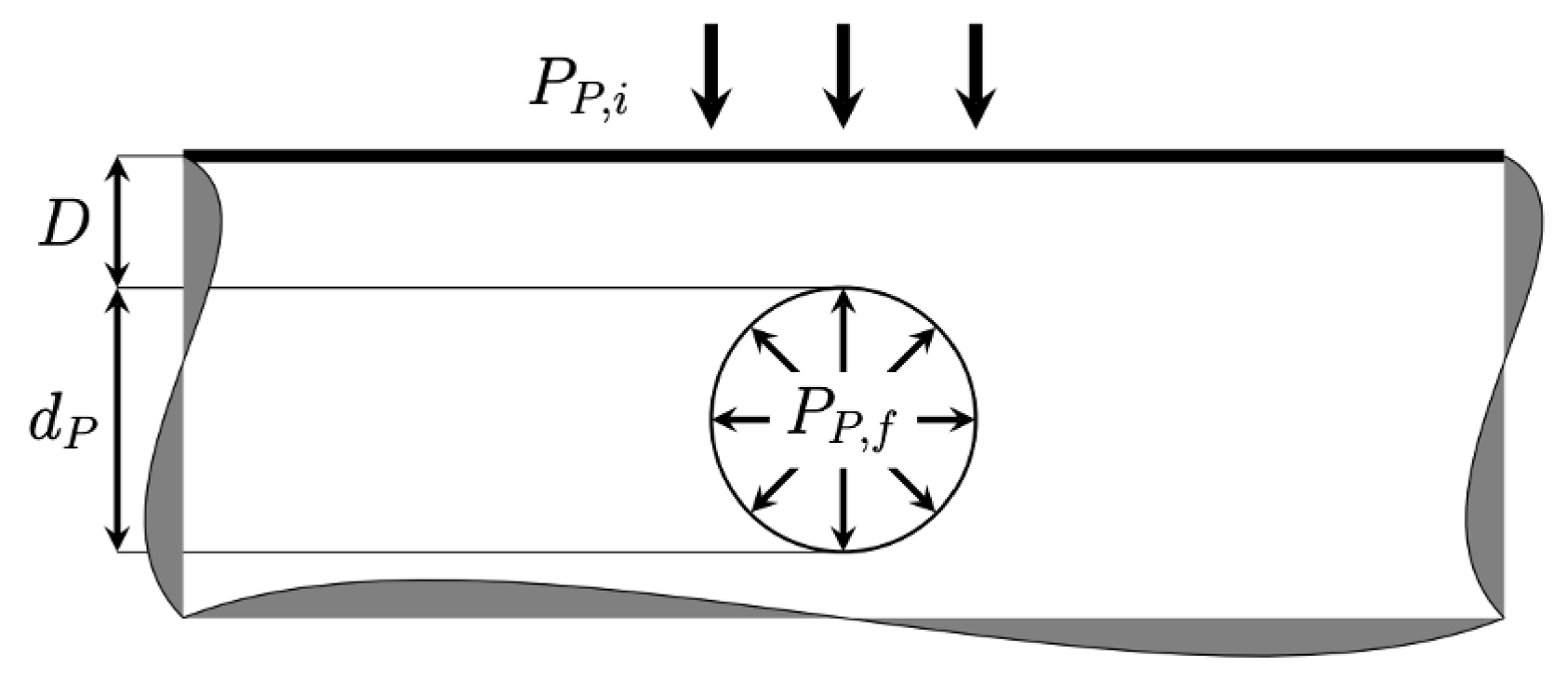
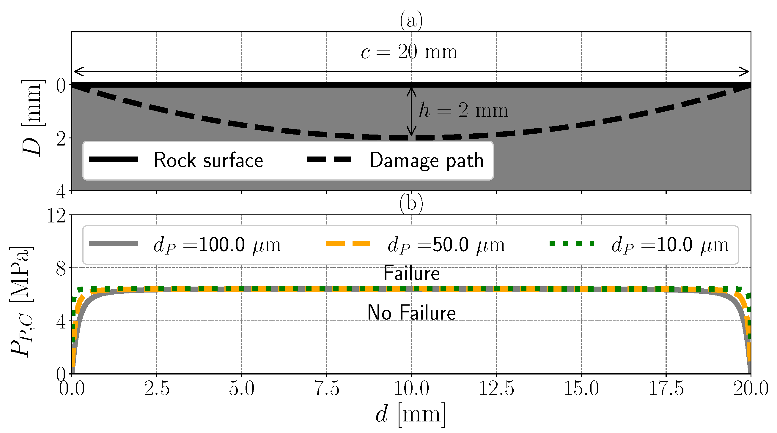
If the pore is near the rock surface, the final pore pressure, required to fracture the rock, is reduced due to an edge effect, caused by the thin wall between the rock surface and the pore. Figure 4 shows a pore with a pressure (i.e., generated plasma pressure), with a diameter (i.e., pore size), and at depth D from the rock surface.
Mammano and Dragoni [72] found that the maximum stress occurring within the rock as a function of the normalized pore size to the pore depth, , and the final pore pressure, , is given by:
In our system, the stress to exceed our failure criterion is 6.42 MPa ( = 6.42 MPa), calculated by Equation (21). Thus, Equation (22) is rearranged to Equation (23) to solve for the critical pore pressure, , which is necessary to surpass the failure criterion ( = 6.42 MPa).
The pore size has three specific typical values (i.e., = 10, 50, or 100 μm), while the pore depth from the rock surface, D, i.e., damage onset depth [48], varies along the distance from the left electrode, d ( mm at the left electrode and mm at the right electrode), which means that the critical pore pressure will vary along the distance from the left electrode, d. To determine this profile of the critical pore pressure, it is necessary to deduce the pore depth, D, as a function of the distance from the left electrode, d.
The damage onset path can determine the relationship between the pore depth, at which the damage onset occurs, and the distance from the left electrode. Inoue et al. [48] used X-Ray Computed Tomography and captured the damage onset path as an arc that connects the two electrodes (i.e., similar to Figure 5a). As the pore depth, D, is largest at the mid-point between the two electrodes (i.e., D = the arc height, h) and is smallest at the electrodes (i.e., D = 0 or 20 mm), we expect a higher critical pore pressure for the damage onset in the middle (i.e., where is large) than for the damage onset near the two electrodes (i.e., where is small), as given by Equation (23). As we use an electrode gap distance that is different from Inoue et al. [48], we assume that the damage path is an ideal arc (i.e., a section from a circle), and we use basic geometry to define a general formula to construct the damage path for any given electrode gap distance as:
where R is the radius of the circle, given by Equation (25), c is the arc radius that is equal to the electrode gap distance of 20 mm, and h is the arc height.
Vazhov et al. [12] showed that the maximum depth at which the damage onset occurs (i.e., the arc height, h), for a 20 mm electrode gap distance, is . Thus, we use Equation (24) to plot the pore depth, D, as a function of the distance from the left electrode, d, (Figure 5a). Further, we use Equation (24) in Equation (23) to plot the critical pore pressure as a function of the distance from the left electrode for the three different pore sizes we investigate (Figure 5b).
Figure 5b shows that, at large distances from the left or the right electrode (i.e., mm, mm, and mm for pore sizes of 10, 50, and 100 mm, respectively), the critical pore pressure, , approaches the failure criterion for granite, ( MPa). At this threshold, the edge effect of the rock surface diminishes. Conversely, at short distances from the left or the right electrodes (i.e., mm, mm, and mm for pore sizes of 10, 50, and 100 mm, respectively), the critical pore pressure becomes equivalent to the rock surface pressure, 0.1 MPa. Thus, less generated plasma is required to induce rock damage in the near-electrode region, compared to the far-electrode region.
3. Results and Discussion
This section outlines the effects of the maximum pulse voltage drop, the pore size, and the pulse rise time on the simulated pore pressure, enabling Plasma Pulse Geo Drilling (PPGD) (i.e., rock damage) in the following order: First, we introduce the results of the calculated voltage drops across the pores and compare these voltage drops with the plasma formation criterion (i.e., Paschen Curve) for the given pore conditions (i.e., pore pressure, pore size, and pore fluid). Next, we introduce the power deposition density results from the ZAPDOS simulations. Lastly, we show the calculated pore pressure increases and compare them with the rock failure criterion.
3.1. Pore Voltage and the Paschen Curve
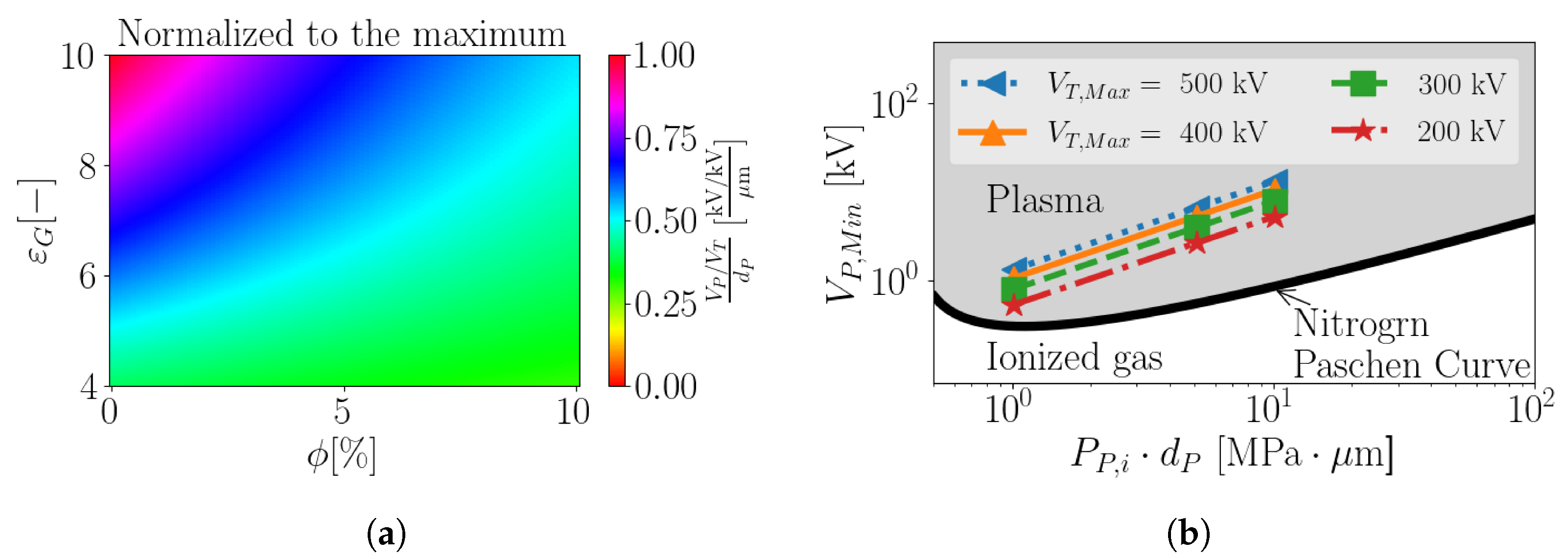
As described, the pore voltage drop determines whether the plasma is likely to occur and determines the electric energy deposition (i.e., pore pressure). Equation (13) shows that the pore voltage drop depends on a combination of operation conditions (i.e., the pulse voltage and the electrode gap distance) and rock parameters (i.e., pore size, porosity, and grain effective relative permittivity). As the dependence of the pore voltage on the operation conditions and the pore size is linear, we use the normalized relative pore voltage drop per unit pore size (hereafter called the relative pore voltage), , to investigate the nonlinear dependence of the pore voltage drop on the rock porosity and the grain effective relative permittivity.
This nonlinearity can be observed in Figure 6a, which shows the relative pore voltage drop as a function of porosity, (ranging from 0 to 10), and of the grain’s effective relative permittivity, (ranging from 4 to 10), for a given electrode gap distance of 20 . We can see that the relative pore voltage drop is proportional to the rock grain’s relative permittivity and is inversely proportional to porosity. A high grain effective relative permittivity and a low porosity, in addition to the large pore size, results in high relative pore voltage drops (Figure 6b), which subsequently results in high pore voltage drops and pore pressures, promoting rock fragmentation. Thus, rock samples with large pores (e.g., sandstone), low porosity (e.g., granite), or high grain effective relative permittivity are favorable to result in high pore voltage drops, increasing the likelihood of plasma formation and inducing high pore pressures that promote rock failure and thus PPGD.
Figure 6b shows a comparison of the Nitrogen Paschen Curve (black line), the plasma formation criterion, and the calculated maximum pore voltage drops, , for the four different maximum pulse voltage drops, ( = 200, 300, 400 and 500 kV), for the three investigated pore sizes, ( = 10, 50, and 100 μm). All pore sizes and total pulse voltages examined here result in pore voltages above the Paschen Curve minimum voltage, so that we can expect plasma formation in all studied cases.
The Paschen Curve shows that a high pore voltage drop, , is required to generate a plasma for high initial gas pressures, , (Figure 6b). This initial pore pressure may increase with depth below the land surface as the lithostatic pressure increases with depth, which suggests that it may be more challenging to generate a plasma at greater depths.
Nonetheless, experimental results by Vazhov et al. [73] and Anders et al. [13] showed that a plasma is indeed generated within pressurized samples, implying that plasma formation still occurs at greater lithostatic pressures, associated with greater depths. Additionally, these experimental results show that a higher fragmentation specific energy (energy/volume) is required at greater depths. Although it is still more difficult for a plasma to form at high lithostatic pressures, the conditions still appear to be favorable within pressurized rock samples. One must also consider the changed stress state at depth, where higher compressive stresses favor borehole breakouts. This complex relationship among depth, pore pressure, lithostatic stress, and plasma formation is a topic for future studies.
3.2. Electric Power Deposition (ZAPDOS Results)
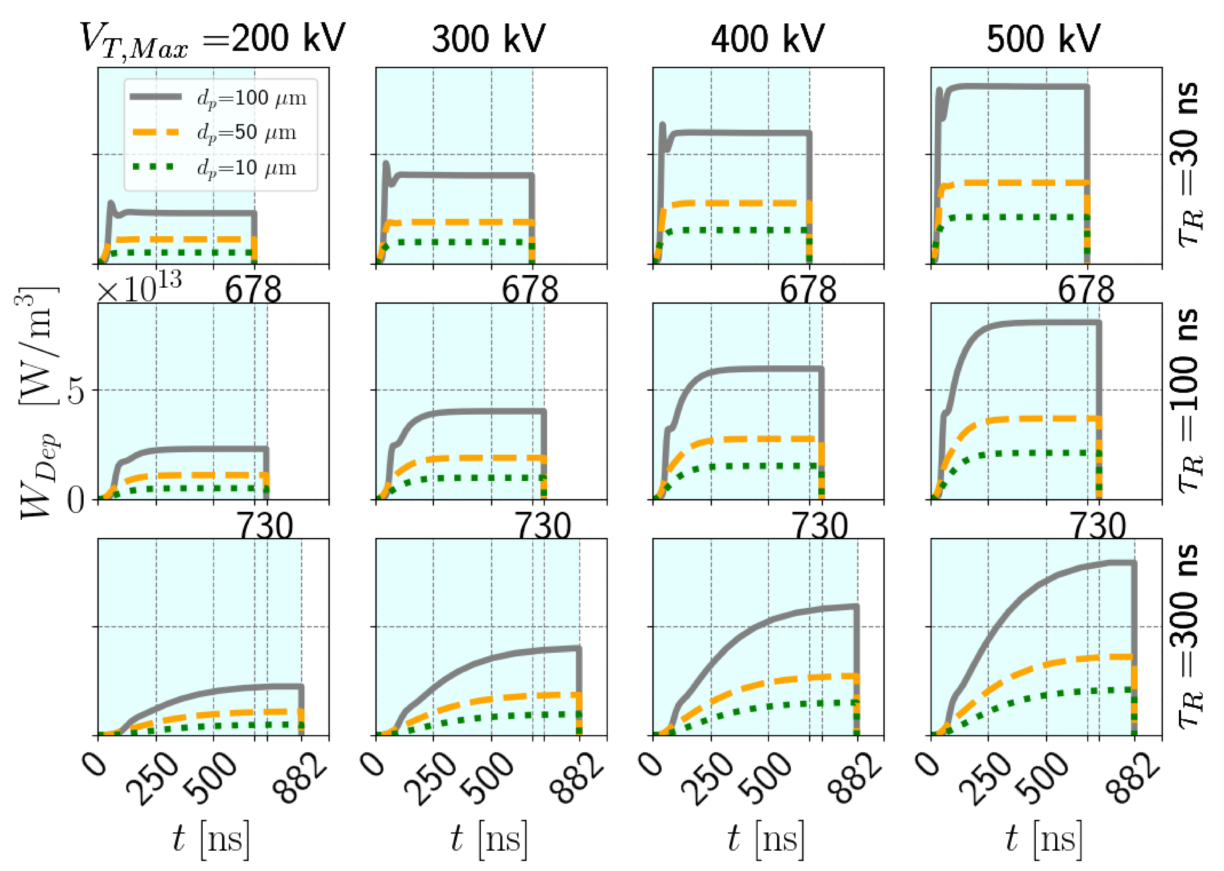
As the aim of PPGD is the creation of high pore pressures that promote rock failure and thus PPGD, we now investigate the power deposition density, , during a voltage pulse to calculate the resultant pore pressure. Figure 7 shows a time-series of power deposition within the plasma from electrons to ions for maximum pulse voltage drops from 200 to 500 kV (left to right column) and rise times from 30 to 300 ns (top row to bottom row). Each subplot depicts results for pore sizes from 10 to 100 μm (green, yellow, and gray lines). The power deposition curves (i.e., Figure 7) tend to follow the same profile as the imposed time-varying pulse voltage (i.e., Figure 2). For instance, for a short pulse rise time of 30 ns, the power deposition density reaches a steady value near 50 ns, however, for a long pulse rise time of 300 ns, the power deposition density continues to increase throughout the simulation. For the selected parameter combinations, the calculated power deposition density range is 0 to . The energy deposited (i.e., the integral of the power deposition density curve) is proportional to the maximum pulse voltage drop and the pore size and inversely proportional to the pulse rise time (Figure 7). Thus, higher maximum pulse voltage drops, larger rock pore sizes, and shorter pulse rise times always promote higher pore pressures.
These trends are observed because increasing both the maximum pulse voltage drop and the pore size increases the pore voltage drop, , across a pore. For instance, the 500 kV pulse with 30 ns rise time yields power densities of 3.7 and 8.1 for the 10 μm and 100 μm pore sizes, respectively, which is a difference of approximately a factor of three (Figure 7). This increase is caused by the higher electric current in larger pores than in smaller pores. The larger pores enable longer traveling distances for the electrons, which frees more electrons via the avalanche process. This in turn results in an increased electric current and, consequently, a higher electric power deposition density.
As shown above, shorter pulse rise times result in greater energies deposited (Figure 7), which increases the likelihood of generating a plasma in a pore. This holds true as a short pulse rise time immediately results in large pore voltage drops. Conversely, a long pulse rise time increases the period during which energy is deposited, while potentially not reaching the same maximum pore voltage drop, . Even though shorter rise times have shorter discharge times, the shorter rise time simulations still result in larger deposited power densities. As PPGD requires high energy deposition to cause rock damage, shorter pulse rise times always cause higher pore pressures, promoting rock damage (i.e., drilling success).
3.3. Pore Pressure and Rock Fracturing
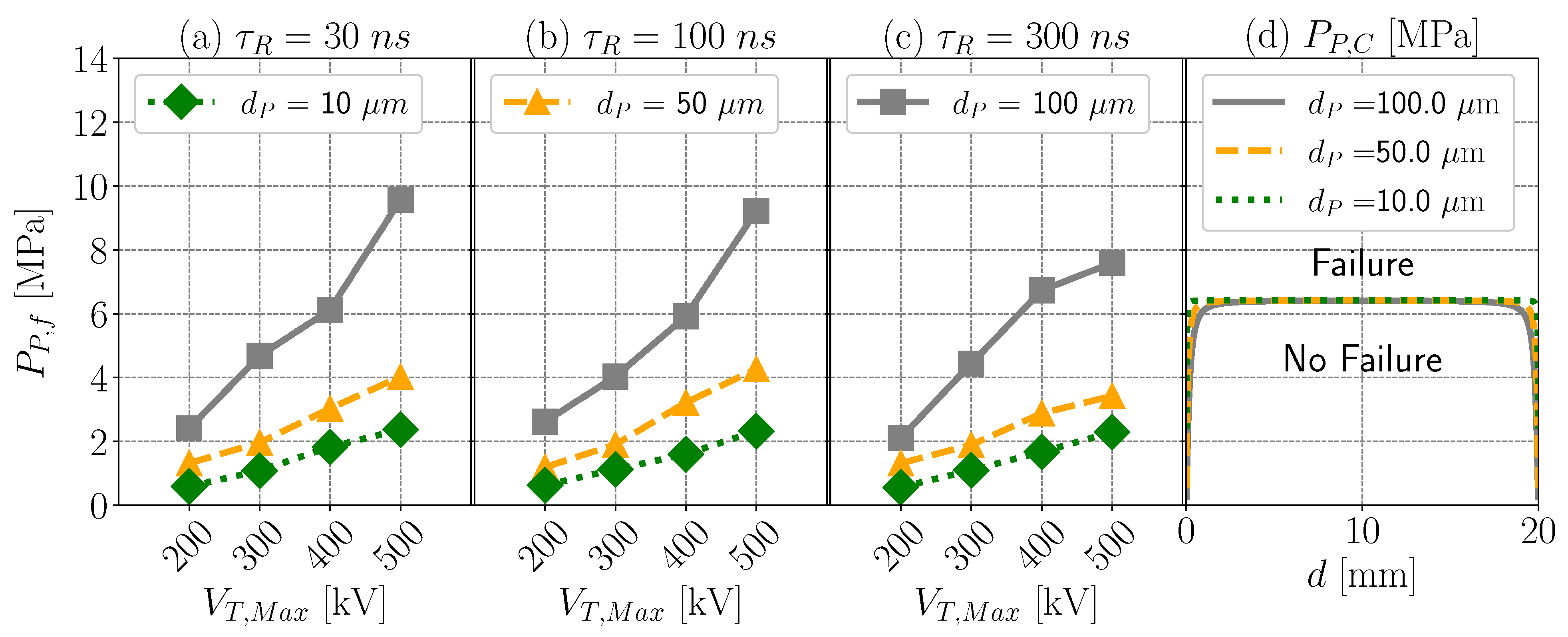
We use the electric power deposition density, calculated with ZAPDOS, to determine the pore pressure, which is shown in Figure 8a,c. The calculated pore pressure, , increases with pore size, , and with maximum pulse voltage drop, (Figure 8a–c). Figure 8d shows the critical pore pressure profile, , with a maximum value of 6.4 MPa, as a function of the distance from the left electrode, d, for all pore sizes for granite. The critical pore pressure reduces to the rock surface pressure, , of 0.1 MPa in regions near the electrodes (i.e., effortless damage onset), while surpassing the critical pore pressure for rock failure in the off-electrode regions is shown to be less likely (i.e., challenging damage onset). Rock failure initiation is therefore most likely to occur near the electrodes.
The final plasma pressure calculated in Figure 8 ranges from 0.56 MPa to 9.57 MPa. Only the 100 μm pore size and maximum pulse voltage drops greater than approximately 400 kV results in rock fracturing in the off-electrode regions, which is consistent with the study results presented by Vazhov et al. [12]. Vazhov et al. [12] show that for a 20 mm electrode gap distance, the voltage required to fracture granite is 270 kV, which aligns well with our results.
The three pore sizes with maximum pulse voltage drops below 400 kV do result in rock fracturing near the electrodes, which is consistent with Lisitsyn et al. [10]. Lisitsyn et al. [10] found only small cracks near the electrodes after the first pulse. This damage path expanded between the two electrodes with each pulse, until a complete path was formed. Several pulses might therefore be required to fracture the granite with maximum pulse voltage drops lower than 400 kV.
When comparing our results to different rock types, it is worth noting that sandstone has been experimentally shown to require less fragmentation specific energy (energy per unit volume) to fracture [10]. Sandstone typically has greater pore sizes and porosities than granite. Larger pore sizes increase the pore voltage drop (Equation (13)), while larger porosities decrease the pore voltage drop (Figure 6a). However, the pore voltage drop dependency on porosity is less pronounced than the pore voltage drop dependency on pore size. This, in addition to the lower tensile strength of sandstone, explains the lower energy required to fracture sandstone.
Water saturation in rock pores has a complicated effect on the fragmentation specific energy. The rock grain relative electric permittivity of dry rock ranges from 5 to 12, however, the rock grain relative electric permittivity of water-saturated rock increases to 17 [74] (Table 6). Thus, the saturation of an initially dry rock sample with water is expected to decrease the porosity of dry pores while increasing the relative electric permittivity of the rock grains. The effect of this change (i.e., increase in water saturation) should be an increase in the pore voltage drop and therefore an increase in the ability to fracture the rock. However, at some degree of pore-space water saturation, the dry pore porosity becomes so small that the ability to fracture decreases again. This complicated trade-off is also seen in the experimental results of Lisitsyn et al. [10]. Future work is needed to study the dependency of fracturing mechanisms on the pore-fluid composition (e.g., air versus water).
4. Conclusions
In this paper, we simulated the fracturing of granite by pore pressure increases, caused by plasma discharge within rock pores, i.e., Plasma Pulse Geo Drilling (PPGD). We provide the following conclusions:
- The voltage drop across a rock pore is typically sufficient to generate a plasma. Using capacitors in series to represent the voltage distribution in rock, we found that the resulting voltage drop was above the minimum required voltage necessary to generate a plasma according to the Paschen Curve. The pore voltage is greater than the minimum required for plasma formation for all pore sizes and maximum plasma voltages tested.
- The energy deposited by a plasma increases with decreasing voltage pulse rise time. We simulated plasma generation in pores with the numerical simulators BOLSIG+ and ZAPDOS. For all pulse rise times, we used a discharge period so that the energy discharged into the rock is the same. However, the longer pulse rise time simulations yield a lower pore voltage drop, although over a longer period of time. Thus, while the energy discharged into the rock is the same, the energy deposited by the plasma is lower for larger voltage pulse rise times. Smaller voltage pulse rise times therefore promote rock fracturing and thus PPGD.
- The energy deposited by a plasma is higher for larger pore sizes. Larger pore sizes yield larger distances over which the electrons have to travel so that the plasma electrons require more energy, which is eventually dissipated into the plasma ions. Higher energy deposition leads to greater pore temperatures, greater pore pressures, and an increased likelihood of rock fracturing.
- In our investigated cases, the pore pressure increase (due to plasma energy deposition) was always large enough to fracture the assumed granite. Rock fractures when the pore pressure exceeds the failure criterion, i.e., the granite fractures when the stress exceeds the sum of the granite’s tensile strength of 6.3 MPa and the adjacent wellbore fluid pressure of 0.1 MPa. In the simulations with a 100 μm pore size, the granite begins to fracture near a maximum applied pulse voltage drop of 400 kV, which is also consistent with experiments reported in the literature.
- The damage onset begins near the electrodes and expands from pulse to pulse. Lower critical pore pressures are sufficient to reach the failure criterion near the electrodes than in the center between the two electrodes. For all simulated pore sizes and maximum voltage drops, this damage onset, occurs near the electrodes, expands from pulse to pulse, eventually leading to fracturing, which is also consistent with experiments reported in the literature.
Author Contributions
Conceptualization, M.E., D.V. and B.M.A.; methodology, M.E., D.V. and B.M.A.; software, M.E.; resources, M.E. and D.V.; data curation, M.E.; writing—original draft preparation, M.E.; writing—review and editing, B.M.A., D.V. and M.O.S.; visualization, M.E.; supervision, B.M.A., D.V. and M.O.S.; project administration, M.O.S.; funding acquisition, M.O.S. and D.V. All authors have read and agreed to the published version of the manuscript.
Funding
This research was funded by Innosuisse–Swiss Innovation Agency—under grant number 28305.1 PFIW-IW.
Acknowledgments
This project was supported by Innosuisse—Swiss Innovation Agency—under grant number 28305.1 PFIW-IW. We appreciate the support from SwissGeoPower. We further thank A.D. Lindsay for his help with the BOLSIG+ and ZAPDOS simulations. M.O.S. further thanks the Werner Siemens Foundation (Werner Siemens-Stiftung, WSS) for their support of the Geothermal Energy and Geofluids (GEG.ethz.ch, accessed on 3 August 2021) group at ETH Zurich (ETHZ), Switzerland.
Conflicts of Interest
The authors confirm that there are no known conflicts of interests associated with this publication and that there has been no significant financial support for this work that could have influenced its outcome.
Nomenclature
The following abbreviations are used in this manuscript:
| m | Mineral Index | - |
| n | Number of Minerals | - |
| Mineral Volume Fraction | - | |
| Mineral Relative Permittivity | - | |
| A | Paschen Curve First Coefficient | |
| B | Paschen Curve Second Coefficient | |
| C | Capacitance | F |
| Single Rock Grain Capacitance | F | |
| Single Rock Pore Capacitance | F | |
| Total Circuit Capacitance | F | |
| Gas Specific Heat at Constant Volume | J/kg/C | |
| Rock Grain Total Capacitance | F | |
| Rock Pore Total Capacitance | F | |
| Electrode Gap Distance | mm | |
| d | The Distance from the Left Electrode | mm |
| Rock Pore Size | μm | |
| Ion Diffusivity | ||
| Ion Mobility | ||
| Electron Diffusivity | ||
| Electron Mobility | ||
| Energy Deposited by Plasma | ||
| L | Capacitor Gap Spacing | m |
| Number of Pores in Rock Sample | - | |
| Initial Pore Pressure | MPa | |
| Final Pore Pressure | MPa | |
| S | Capacitor Surface Area | |
| Rock Layer Cross-sectional Area | ||
| t | Simulation Time | ns |
| Initial Pore Temperature | ||
| Final Pore Temperature | ||
| Single Pore Voltage Drop | ||
| Paschen Curve Threshold | ||
| Pulse Voltage Drop | kV | |
| Maximum Pulse Voltage Drop | kV | |
| Maximum Pore Voltage | kV | |
| Rock Grains Total Voltage Drop | kV | |
| Rock Pores Total Voltage Drop | kV | |
| Power Deposition Density by Plasma | ||
| Townsend Ionization Coefficient | ||
| Townsend Excitation Coefficient | ||
| Townsend elastic collision coefficient | ||
| N | Number Density | |
| N | Number Density | |
| Secondary Ionization Coefficient | - | |
| Mean Electron Energy | eV | |
| Nitrogen Ionization Energy | eV | |
| Pore Temperature Increase | ||
| Vacuum Permittivity Constant | F/m | |
| Rock Effective Relative Permittivity | - | |
| Pore Fluid Relative Permittivity | - | |
| Nitrogen Density | ||
| Tensile Strength | MPa | |
| Plasma Discharge Time | ns | |
| Pulse Rise Time | ns | |
| Rock Porosity | - | |
| Critical Pore Pressure, | MPa | |
| D | Pore Depth | μm |
References
- Tester, J.; Anderson, B.; Batchelor, A.; Blackwell, D.; DiPippo, R.; Drake, E.; Garnish, J.; Livesay, B.; Moore, M.; Nichols, K.; et al. The Future of Geothermal Energy; Idaho National Laboratory: Idaho Falls, ID, USA, 2006. [Google Scholar]
- Al-Khdheeawi, E.A.; Mahdi, D.S.; Feng, R. Lithology Determination from Drilling Data Using Artificial Neural Network. In Proceedings of the 53rd US Rock Mechanics/Geomechanics Symposium, New York, NY, USA, 23–26 June 2019. [Google Scholar]
- Al-Khdheeawi, E.A.; Mahdi, D.S. Apparent viscosity prediction of water-based muds using empirical correlation and an artificial neural network. Energies 2019, 12, 3067. [Google Scholar] [CrossRef] [Green Version]
- Mahdi, D.S. Predicting Drilling Rate of Penetration Using Artificial Neural Networks. IOP Conf. Ser. Mater. Sci. Eng. 2021, 1067, 012150. [Google Scholar] [CrossRef]
- Schiegg, H.O.; Rødland, A.; Zhu, G.; Yuen, D.A. Electro-pulse-boring (EPB): Novel super-deep drilling technology for low cost electricity. J. Earth Sci. 2015, 26, 37–46. [Google Scholar] [CrossRef]
- Vogler, D.; Walsh, S.D.C.; von Rohr, P.R.; Saar, M.O. Simulation of rock failure modes in thermal spallation drilling. Acta Geotech. 2020, 15, 2327–2340. [Google Scholar] [CrossRef]
- Rossi, E.; Adams, B.; Vogler, D.; Rudolf von Rohr, P.; Kammermann, B.; Saar, M.O. Advanced drilling technologies to improve the economics of deep geo-resource utilization. In Proceedings of the 2nd Applied Energy Symposium: MIT A+ B (MITAB 2020) (Virtual), Boston, MA, USA, 13–14 August 2020; Geothermal Energy & Geofluids, ETH Zurich: Zurich, Switzerland, 2020; p. 148. [Google Scholar]
- Vorob’ev, A.; Vorob’ev, G.; Chepikov, A. Regularities of breakdown of a solid dielectric at the interface with a liquid dielectric under the action of a voltage pulse. Vyshaya Shkola Mosc. 1961. (In Russian) [Google Scholar]
- Boev, S.; Vajov, V.; Levchenko, B.; Jgun, D.; Muratov, V.; Peltsman, S.; Adam, A.; Uemura, K. Electropulse technology of material destruction and boring. In Proceedings of the 11th IEEE International Pulsed Power Conference, Baltimore, MA, USA, 29 June–2 July 1997; Volume 1, pp. 220–225. [Google Scholar] [CrossRef]
- Lisitsyn, I.V.; Inoue, H.; Nishizawa, I.; Katsuki, S.; Akiyama, H. Breakdown and destruction of heterogeneous solid dielectrics by high voltage pulses. J. Appl. Phys. 1998, 84, 6262–6267. [Google Scholar] [CrossRef]
- Timoshkin, I.V.; Mackersie, J.W.; MacGregor, S.J. Plasma channel miniature hole drilling technology. IEEE Trans. Plasma Sci. 2004, 32, 2055–2061. [Google Scholar] [CrossRef]
- Vazhov, V.F.; Gafarov, R.R.; Datskevich, S.Y.; Zhurkov, M.Y.; Muratov, V.M. Electric-pulse breakdown and the breakage of granite. Tech. Phys. 2010, 55, 833–838. [Google Scholar] [CrossRef]
- Anders, E.; Voigt, M.; Lehmann, F.; Mezzetti, M. Electric Impulse Drilling: The Future of Drilling Technology Begins Now. In Proceedings of the 36th International Conference on Ocean, Offshore & Arctic Engineering, Trondheim, Norway, 25–30 June 2017; Volume 8. [Google Scholar] [CrossRef]
- Ushakov, V.Y.; Vajov, V.F.; Zinoviev, N.T. Electro-Discharge Technology for Drilling Wells and Concrete Destruction; Springer: Cham, Switzerland, 2019. [Google Scholar]
- Li, C.; Duan, L.; Tan, S.; Chikhotkin, V.; Fu, W. Damage Model and Numerical Experiment of High-Voltage Electro Pulse Boring in Granite. Energies 2019, 12, 727. [Google Scholar] [CrossRef] [Green Version]
- Li, C.; Duan, L.; Wu, L.; Tan, S.; Zheng, J.; Chikhotkin, V. Experimental and numerical analyses of electro-pulse rock-breaking drilling. J. Nat. Gas Sci. Eng. 2020, 77, 103263. [Google Scholar] [CrossRef]
- Vogler, D.; Walsh, S.D.; Saar, M.O. A numerical investigation into key factors controlling hard rock excavation via electropulse stimulation. J. Rock Mech. Geotech. Eng. 2020, 12, 793–801. [Google Scholar] [CrossRef]
- Zhu, X.; Luo, Y.; Liu, W. On the rock-breaking mechanism of plasma channel drilling technology. J. Pet. Sci. Eng. 2020, 194, 107356. [Google Scholar] [CrossRef]
- Zhu, X.; Luo, Y.; Liu, W.; He, L.; Gao, R.; Jia, Y. On the Mechanism of High-Voltage Pulsed Fragmentation from Electrical Breakdown Process. Rock Mech. Rock Eng. 2021, 1–24. [Google Scholar] [CrossRef]
- Browning, J.A. Flame Jet Drilling and Chambering to Great Depths in Crystalline Rock; Technical Report; Advanced Research Projects Agency: Hanover, NH, USA, 1982. [Google Scholar]
- Rauenzahn, R.; Tester, J. Rock failure mechanisms of flame-jet thermal spallation drilling—Theory and experimental testing. Int. J. Rock Mech. Min. Sci. Geomech. Abstr. 1989, 26, 381–399. [Google Scholar] [CrossRef]
- Potter, R.M.; Tester, J.W. Continuous Drilling of Vertical Boreholes by Thermal Processes: Including Rock Spallation and Fusion. U.S. Patent 5,771,984, 30 June 1998. [Google Scholar]
- Augustine, C.; Tester, J.W.; Anderson, B.; Petty, S.; Livesay, B. A comparison of geothermal with oil and gas well drilling costs. In Proceedings of the 31st Workshop on Geothermal Reservoir Engineering, Stanford, CA, USA, 30 January–1 February 2006; Curran Associates Inc.: New York, NY, USA, 2006; pp. 5–19. [Google Scholar]
- Augustine, C.R. Hydrothermal Spallation Drilling and Advanced Energy Conversion Technologies for Engineered Geothermal Systems. Ph.D. Thesis, Massachusetts Institute of Technology, Cambridge, MA, USA, 2009. [Google Scholar]
- Von Rohr, P.R.; Rothenfluh, T.; Schuler, M. Rock Drilling in Great Depths by Thermal Fragmentation Using Highly Exothermic Reactions Evolving in the Environment of a Water-Based Drilling Fluid. U.S. Patent 8,967,293, 3 March 2015. [Google Scholar]
- Rudolf von Rohr, P.; Kant, M.; Rossi, E. An Apparatus for Thermal Spallation of a Borehole. European Patent EP3450675A1, 28 August 2017. [Google Scholar]
- Kant, M.A.; Rossi, E.; Duss, J.; Amann, F.; Saar, M.O.; von Rohr, P.R. Demonstration of thermal borehole enlargement to facilitate controlled reservoir engineering for deep geothermal, oil or gas systems. Appl. Energy 2018, 212, 1501–1509. [Google Scholar] [CrossRef]
- Rossi, E.; Kant, M.A.; Madonna, C.; Saar, M.O.; von Rohr, P.R. The effects of high heating rate and high temperature on the rock strength: Feasibility study of a thermally assisted drilling method. Rock Mech. Rock Eng. 2018, 51, 2957–2964. [Google Scholar] [CrossRef]
- Rossi, E.; Jamali, S.; Wittig, V.; Saar, M.O.; von Rohr, P.R. A combined thermo-mechanical drilling technology for deep geothermal and hard rock reservoirs. Geothermics 2020, 85, 101771. [Google Scholar] [CrossRef]
- Rossi, E.; Jamali, S.; Saar, M.O.; von Rohr, P.R. Field test of a Combined Thermo-Mechanical Drilling technology. Mode I: Thermal spallation drilling. J. Pet. Sci. Eng. 2020, 190, 107005. [Google Scholar] [CrossRef]
- Rossi, E.; Jamali, S.; Schwarz, D.; Saar, M.O.; von Rohr, P.R. Field test of a Combined Thermo-Mechanical Drilling technology. Mode II: Flame-assisted rotary drilling. J. Pet. Sci. Eng. 2020, 190, 106880. [Google Scholar] [CrossRef]
- Rossi, E.; Saar, M.O.; Rudolf von Rohr, P. The influence of thermal treatment on rock–bit interaction: A study of a combined thermo–mechanical drilling (CTMD) concept. Geotherm. Energy 2020, 8, 1–22. [Google Scholar] [CrossRef]
- Farmer, I.; Attewell, P. Rock penetration by high velocity water jet: A review of the general problem and an experimental study. Int. J. Rock Mech. Min. Sci. Geomech. Abstr. 1965, 2, 135–153. [Google Scholar] [CrossRef]
- Harris, H.; Mellor, M. Cutting rock with water jets. Int. J. Rock Mech. Min. Sci. Geomech. Abstr. 1974, 11, 343–358. [Google Scholar] [CrossRef]
- Buset, P.; Riiber, M.; Eek, A. Jet drilling tool: Cost-effective lateral drilling technology for enhanced oil recovery. In Proceedings of the SPE/ICoTA Coiled Tubing Roundtable, Houston, TX, USA, 7–8 March 2001. [Google Scholar]
- Bruni, M.A.; Biasotti, J.H.; Salomone, G.D. Radial drilling in Argentina. In Proceedings of the Latin American & Caribbean Petroleum Engineering Conference, Buenos Aires, Argentina, 15–18 April 2007. [Google Scholar]
- Reinsch, T.; Paap, B.; Hahn, S.; Wittig, V.; van den Berg, S. Insights into the radial water jet drilling technology—Application in a quarry. J. Rock Mech. Geotech. Eng. 2018, 10, 236–248. [Google Scholar] [CrossRef]
- Moavenzadeh, F.; Williamson, R.; McGarry, F. Laser Assisted Rock Fracture; Technical Report; Massachusetts Institute of Technology: Cambridge, MA, USA, 1967. [Google Scholar]
- Farra, G. Experimental Observations of Rock Failure due to Laser Radiation. Ph.D. Thesis, Massachusetts Institute of Technology, Cambridge, MA, USA, 1969. [Google Scholar]
- Parker, R.; Xu, Z.; Reed, C.; Graves, R.; Gahan, B.; Batarseh, S. Drilling large diameter holes in rocks using multiple laser beams. In Proceedings of the International Congress on Applications of Lasers & Electro-Optics, Jacksonville, FL, USA, 13–16 October 2003; Volume 1, p. 504. [Google Scholar] [CrossRef]
- Xu, Z.; Reed, C.B.; Parker, R.; Graves, R. Laser spallation of rocks for oil well drilling. In Proceedings of the International Congress on Applications of Lasers &Electro-Optics, San Francisco, CA, USA, 4–7 October 2004; Volume 1, p. 1803. [Google Scholar]
- Ezzedine, S.; Rubenchik, A.; Yamamoto, R.; Vorobiev, O. Laser-enhanced drilling for subsurface EGS applications. GRC Trans. 2012, 36, 287–290. [Google Scholar]
- Buckstegge, F.; Michel, T.; Zimmermann, M.; Roth, S.; Schmidt, M. Advanced Rock Drilling Technologies Using High Laser Power. Phys. Procedia 2016, 83, 336–343. [Google Scholar] [CrossRef] [Green Version]
- Rodland, A. Deep Geothermal Energy; Photonics for Harvesting. In Proceedings of the Swissphotonics-Workshop: Photonics for Deep Geothermal Energy Harvesting, Neuchatel, Switzerland, 7 November 2012; Commission for Technology and Innovation CTI: Neuchatel, Switzerland, 2012; pp. 125–129. [Google Scholar]
- Chen, F.F. Introduction to Plasma Physics, 3rd ed.; Springer Science & Business Media: Cham, Switzerland, 2018. [Google Scholar] [CrossRef]
- Lehr, J.; Ron, P. Foundations of Pulsed Power Technology; John Wiley & Sons, Ltd.: Hoboken, NJ, USA, 2017. [Google Scholar] [CrossRef]
- Jonscher, A.; Lacoste, R. On a cumulative model of dielectric breakdown in solids. IEEE Trans. Electr. Insul. 1984, 6, 567–577. [Google Scholar] [CrossRef]
- Inoue, H.; Lisitsyn, I.V.; Akiyama, H.; Nishizawa, I. Pulsed Electric Breakdown and Destruction of Granite. Jpn. J. Appl. Phys. 1999, 38, 6502–6505. [Google Scholar] [CrossRef]
- Budenstein, P.P. On the Mechanism of Dielectric Breakdown of Solids. IEEE Trans. Electr. Insul. 1980, 3, 225–240. [Google Scholar] [CrossRef]
- Walsh, S.D.; Vogler, D. Simulating electropulse fracture of granitic rock. Int. J. Rock Mech. Min. Sci. 2020, 128, 104238. [Google Scholar] [CrossRef] [Green Version]
- Vazhov, V.F.; Gafarov, R.R.; Datskevich, S.Y.; Zhurkov, M.Y.; Lopatin, V.V.; Muratov, V.M.; Jeffryes, B. Breakage of rocks by pulsed electric discharge at elevated pressures and temperatures. Tech. Phys. Lett. 2011, 37, 383–386. [Google Scholar] [CrossRef]
- Hagelaar, G.J.M.; Pitchford, L.C. Solving the Boltzmann equation to obtain electron transport coefficients and rate coefficients for fluid models. Plasma Sources Sci. Technol. 2005, 14, 722–733. [Google Scholar] [CrossRef]
- Lindsay, A.D.; Graves, D.B.; Shannon, S.C. Fully coupled simulation of the plasma liquid interface and interfacial coefficient effects. J. Phys. D Appl. Phys. 2016, 49, 235204. [Google Scholar] [CrossRef] [Green Version]
- Schild, M.; Siegesmund, S.; Vollbrecht, A.; Mazurek, M. Characterization of granite matrix porosity and pore-space geometry by in situ and laboratory methods. Geophys. J. Int. 2001, 146, 111–125. [Google Scholar] [CrossRef] [Green Version]
- Hiraga, T.; Nagase, T.; Akizuki, M. The structure of grain boundaries in granite-origin ultramylonite studied by high-resolution electron microscopy. Phys. Chem. Miner. 1999, 26, 617–623. [Google Scholar] [CrossRef]
- Hõbejõgi, T. Compact Pulse Modulator for Plasma Channel Drilling. Ph.D. Thesis, ETH Zurich, Zurich, Switzerland, 2014. [Google Scholar] [CrossRef]
- Uhlig, H.H.; Keyes, F.G. The Dependence of the Dielectric Constants of Gases on Temperature and Density. J. Chem. Phys. 1933, 1, 155–159. [Google Scholar] [CrossRef]
- Nelson, S.O.; Lindroth, D.P.; Blake, R.L. Dielectric properties of selected minerals at 1 to 22 GHz. Geophysics 1989, 54, 1344–1349. [Google Scholar] [CrossRef]
- Zheng, Y.; Wang, S.; Feng, J.; Ouyang, Z.; Li, X. Measurement of the complex permittivity of dry rocks and minerals: Application of polythene dilution method and Lichtenecker’s mixture formulae. Geophys. J. Int. 2005, 163, 1195–1202. [Google Scholar] [CrossRef] [Green Version]
- Stuart, M.R. Dielectric Constant of Quartz as a Function of Frequency and Temperature. J. Appl. Phys. 1955, 26, 1399–1404. [Google Scholar] [CrossRef]
- Olhoeft, G.R. Tables of Room Temperature Electrical Properties for Selected Rocks and Minerals with Dielectric Permittivity Statistics; Technical Report; U.S. Geological Survey: Reston, VA, USA, 1979. [Google Scholar] [CrossRef] [Green Version]
- Nakamura, T.; Shimizu, M.; Kimura, H.; Sato, R. Effective permittivity of amorphous mixed materials. Electron. Commun. Jpn. (Part I Commun.) 2005, 88, 1–9. [Google Scholar] [CrossRef]
- Townsend, J. Electrons in Gases; Hutchinson’s Scientific and Technical Publications: London, UK, 1947. [Google Scholar]
- Husain, E.; Nema, R.S. Analysis of Paschen Curves for air, N2 and SF6 Using the Townsend Breakdown Equation. IEEE Trans. Electr. Insul. 1982, 4, 350–353. [Google Scholar] [CrossRef]
- Luque, A. BOLtzmann Equation Solver Open Source Library (BOLOS). 2015. Available online: https://bolos.readthedocs.io/en/latest/ (accessed on 28 March 2019).
- Permann, C.J.; Gaston, D.R.; Andrš, D.; Carlsen, R.W.; Kong, F.; Lindsay, A.D.; Miller, J.M.; Peterson, J.W.; Slaughter, A.E.; Stogner, R.H.; et al. MOOSE: Enabling massively parallel multiphysics simulation. SoftwareX 2020, 11, 100430. [Google Scholar] [CrossRef]
- Zavilopulo, A.N.; Chipev, F.F.; Shpenik, O.B. Ionization of nitrogen, oxygen, water, and carbon dioxide molecules by near-threshold electron impact. Tech. Phys. 2005, 50, 402–407. [Google Scholar] [CrossRef]
- Paul, B. A Modification of the Coulomb-Mohr Theory of Fracture. J. Appl. Mech. 1961, 28, 259–268. [Google Scholar] [CrossRef]
- Labuz, J.F.; Zang, A. Mohr–Coulomb Failure Criterion. Rock Mech. Rock Eng. 2012, 45, 975–979. [Google Scholar] [CrossRef] [Green Version]
- Perras, M.A.; Diederichs, M.S. A Review of the Tensile Strength of Rock: Concepts and Testing. Geotech. Geol. Eng. 2014, 32, 525–546. [Google Scholar] [CrossRef]
- Parkhomenko, E.I. Brief Introduction to the Piezoelectric Effect. In Electrification Phenomena in Rocks; Springer US: Boston, MA, USA, 1971; pp. 3–33. [Google Scholar]
- Mammano, G.S.; Dragoni, E. Stress concentrations around a pressurized hole close to a uniformly loaded boundary. J. Strain Anal. Eng. Des. 2009, 44, 569–575. [Google Scholar] [CrossRef]
- Vazhov, V.F.; Datskvich, S.Y.; Zhurkov, M.Y.; Muratov, V.M. Electric pulse breakdown and rock fracture in a coupled environment of increased pressure and temperature. J. Phys. Conf. Ser. 2014, 552, 012050. [Google Scholar] [CrossRef] [Green Version]
- Parkhomenko, E. Dielectric Properties of Rocks. In Electrical Properties of Rocks; Springer US: Boston, MA, USA, 1967; pp. 11–57. [Google Scholar]
Figure 1.
(a) Schematic of the one-dimensional configuration used for the simulation. The conducting path represents the path of current flow through the rock mass,where the damage occurs between the two electrodes. (b) The compact form of the same schematic, enabling utilization of the capacitance circuit model (Section 2.2.2).

Figure 2.
The black line is the normalized pulse profile used in the experiment by Lisitsyn et al. [10]). Solid red, dashed blue, and dotted green lines are the normalized pulse profiles used in the simulations for three different values of the rise time, . The discharge time, , is varied with the rise time, , to obtain the same area underneath the experimental and simulation pulse profiles.

Figure 3.
(a) The equivalent circuit for the single rock pore unit (red capacitor) and the single rock grain unit (gray capacitor), which are exposed to the pulse voltage drop, VT, as demonstrated in Figure 1b. (b) Sketch of the one-dimensional plasma simulation domain (used in ZAPDOS Lindsay et al. [53]), which is a single rock pore.

Figure 4.
Schematic of the edge effect, where the final pore pressure, , is amplified due to the close proximity to the rock surface.
Figure 4.
Schematic of the edge effect, where the final pore pressure, , is amplified due to the close proximity to the rock surface.

Figure 5.
(a) The profile of the fracture depth, D, and (b) the critical pore pressure, , (i.e., the rock failure criterion) as a function of the distance from the left electrode, d, for the three investigated pore sizes, .
Figure 5.
(a) The profile of the fracture depth, D, and (b) the critical pore pressure, , (i.e., the rock failure criterion) as a function of the distance from the left electrode, d, for the three investigated pore sizes, .

Figure 6.
(a) The relative pore voltage as a function of rock porosity, φ, and the rock grain relative permittivity, εG, for a given electrode gap distance of dE = 20 mm. (b) Comparison of the Nitrogen Paschen Curve, and the maximum pore voltage drops, calculated for different maximum pulse voltage drops, VT,Max.

Figure 7.
The deposited electric power density in a single pore, , versus time, t, for the three pore widths, , investigated. The cyan area represents the plasma discharge time, which varies with the pulse rise time. The four columns represent four values of the maximum pulse voltage drop, , and the three rows represent three values of the pulse rise time, .

Figure 8.
(a–c) The calculated pore pressure (i.e., plasma pressure), , versus the maximum pulse voltage drop, , for the three investigated pore sizes, , under three pulse rise times, . (d) The critical pore pressure, , as a function of the distance from the left electrode, d, for the three pore sizes.The calculated plasma pressure.


Table 1.
Model parameters. The groups (separated by a horizontal line) represent the parameters of the pulse, the rock, and the pore fluid.
Table 1.
Model parameters. The groups (separated by a horizontal line) represent the parameters of the pulse, the rock, and the pore fluid.
| Name | Symbol | Value | Unit |
|---|---|---|---|
| Pulse Maximum Voltage Drop | 200, 300, 400, or 500 | ||
| Electrode Gap Distance | 20 | ||
| Pulse Rise Time | 30, 100, or 300 | ns | |
| Pulse Discharge Time | 678, 730, or 882 | ns | |
| Rock Type | - | Granite | - |
| Rock Pore Size | 10, 50, or 100 | μm | |
| Rock Porosity | 1 | % | |
| Rock Tensile Strength | 6.3 | ||
| Rock Grains Effective Relative Permittivity | 5.58 | - | |
| Pore Fluid | - | Nitrogen | - |
| Pore Fluid Relative Permittivity | 1 | - | |
| Pore Initial Pressure | 0.1 | MPa | |
| Pore Initial Temperature | 15 | ||
| Nitrogen Paschen Curve First Constant | A | 9 | |
| Nitrogen Paschen Curve Second Constant | B | 256.5 | |
| Secondary ionization coefficient | 0.01 | - |
Obtained or adapted from the literature and justified in Section 2.1. Calculated. Assumed—justified in Section 2.1. Initial operation conditions, which represent the ambient conditions.
Table 2.
Assumed granite mineral volume fractions, , and related electric permittivity values, [17,58,59,60,61].
| Mineral | Reference | Reference | ||
|---|---|---|---|---|
| K-feldspar | 45% | Vogler et al. [17] | 6.03 | Nelson et al. [58] |
| Plagioclase | 20% | Vogler et al. [17] | 6.34 | Zheng et al. [59] |
| Quartz | 30% | Vogler et al. [17] | 4.50 | Stuart [60] |
| Biotite | 5% | Vogler et al. [17] | 6.30 | Olhoeft [61] |
| Effective relative electric permittivity | 5.58 | Equation (14) | ||
Table 3.
ZAPDOS input parameters for our plasma formation simulations.
| Name | Symbol | Values | Unit |
|---|---|---|---|
| Pore Fluid | - | Nitrogen | - |
| Pore Size | 10, 50, 100 | μm | |
| Pore Voltage Drop | Variable | kV | |
| Pore Initial Pressure | 0.1 | MPa | |
| Pore Initial Temperature | 15 | MPa | |
| Nitrogen Ionization Energy | 15.58 | eV | |
| Ion Mobility | |||
| Ion Diffusivity | |||
| Electron Mobility | Variable | ||
| Electron Diffusivity | Variable | ||
| Townsend Ionization Coefficient | Variable | ||
| Townsend Excitation Coefficient | Variable | ||
| Townsend Elastic Collision Coefficient | Variable |
Calculated by Equation (13), values are also given in (Section 3.1). Obtained from the study by Zavilopulo et al. [67]. Obtained from the study by Lindsay et al. [53]. Obtained using BOLSIG+ [52].
Publisher’s Note: MDPI stays neutral with regard to jurisdictional claims in published maps and institutional affiliations. |
© 2021 by the authors. Licensee MDPI, Basel, Switzerland. This article is an open access article distributed under the terms and conditions of the Creative Commons Attribution (CC BY) license (https://creativecommons.org/licenses/by/4.0/).
Share and Cite
MDPI and ACS Style
Ezzat, M.; Vogler, D.; Saar, M.O.; Adams, B.M. Simulating Plasma Formation in Pores under Short Electric Pulses for Plasma Pulse Geo Drilling (PPGD). Energies 2021, 14, 4717. https://doi.org/10.3390/en14164717
AMA Style
Ezzat M, Vogler D, Saar MO, Adams BM. Simulating Plasma Formation in Pores under Short Electric Pulses for Plasma Pulse Geo Drilling (PPGD). Energies. 2021; 14(16):4717. https://doi.org/10.3390/en14164717
Chicago/Turabian StyleEzzat, Mohamed, Daniel Vogler, Martin O. Saar, and Benjamin M. Adams. 2021. "Simulating Plasma Formation in Pores under Short Electric Pulses for Plasma Pulse Geo Drilling (PPGD)" Energies 14, no. 16: 4717. https://doi.org/10.3390/en14164717
Note that from the first issue of 2016, this journal uses article numbers instead of page numbers. See further details here.