
Integrated Optimal Design of Permanent Magnet Synchronous Generator for Smart Wind Turbine Using Genetic Algorithm

 , ,
, ,  , ,
, ,
Abstract
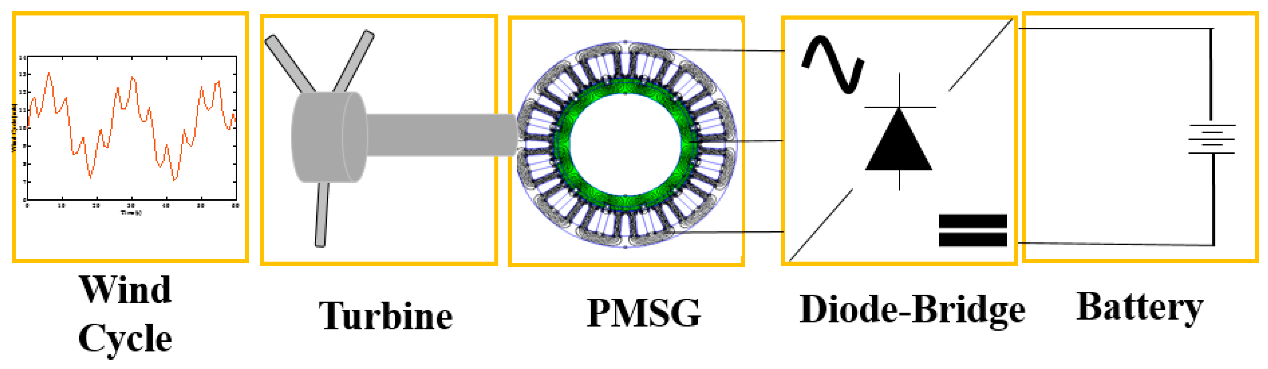
:1. Introduction
2. Multi-Physics Models of Permanent Magnet Synchronous Generator
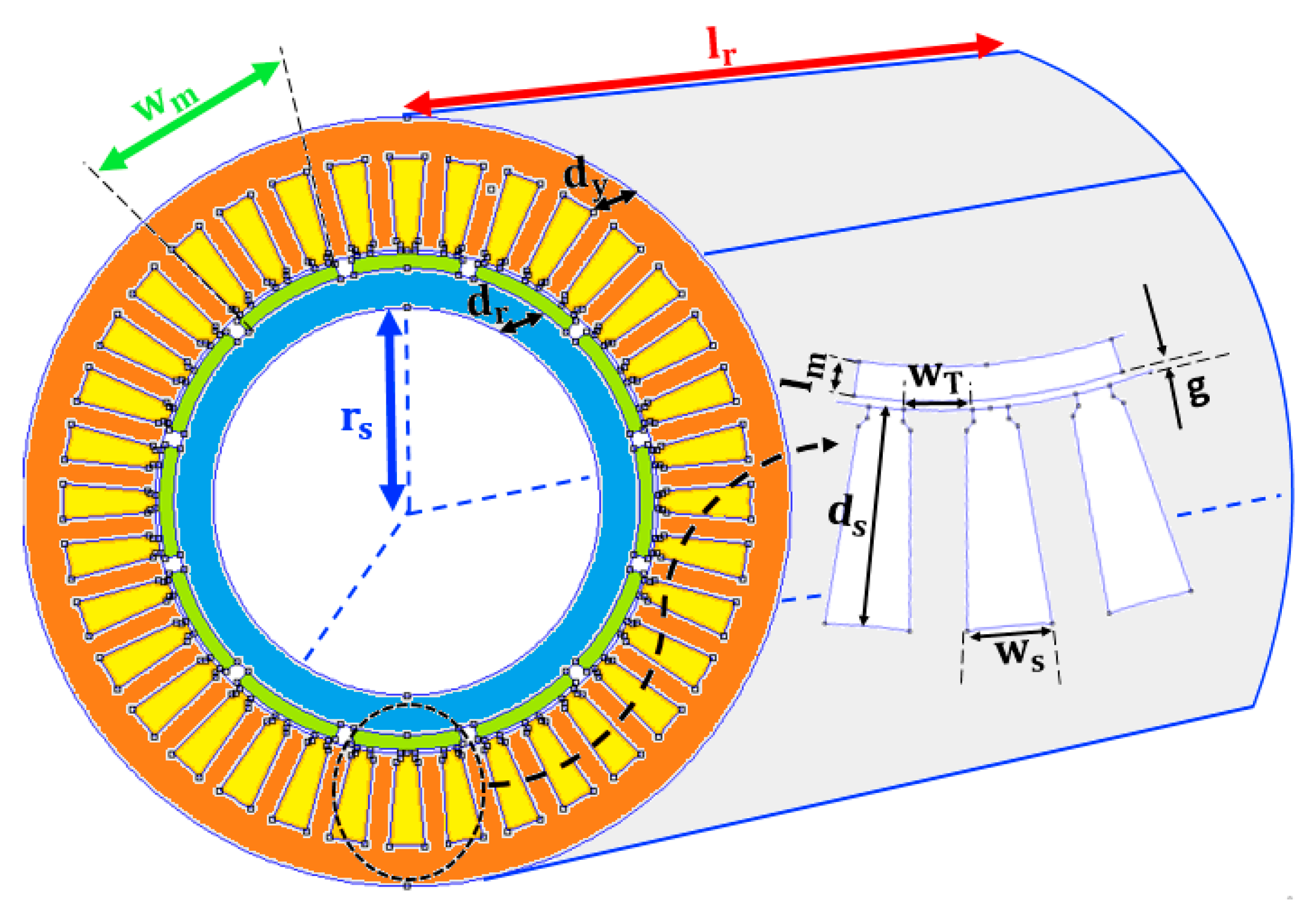
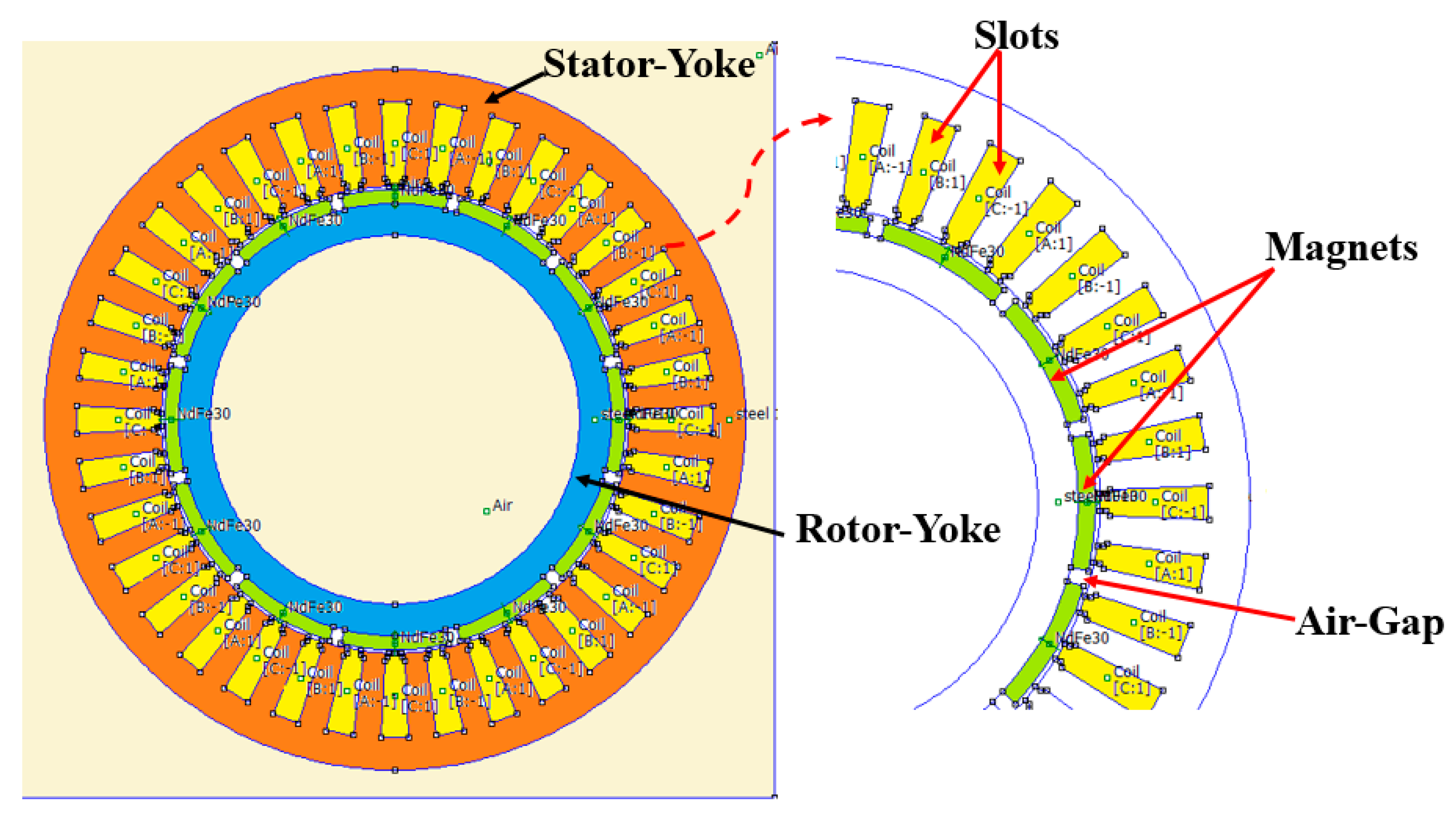
2.1. Structural Model
2.2. Magnetic Model
2.3. Electrical Model
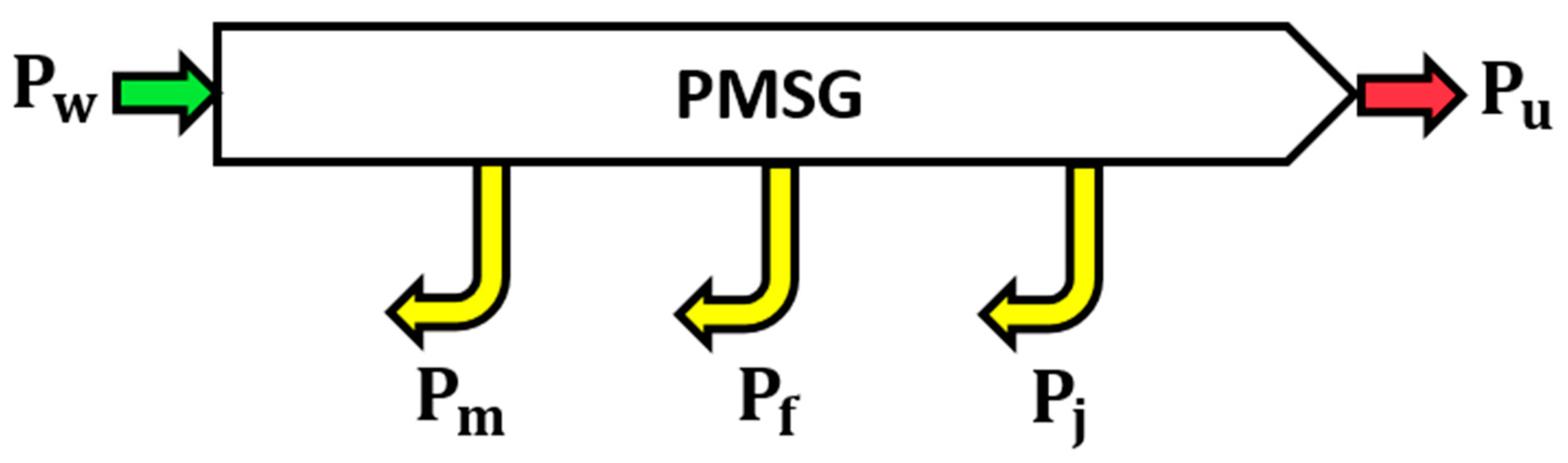
2.4. Losses Model and Generator Efficiency
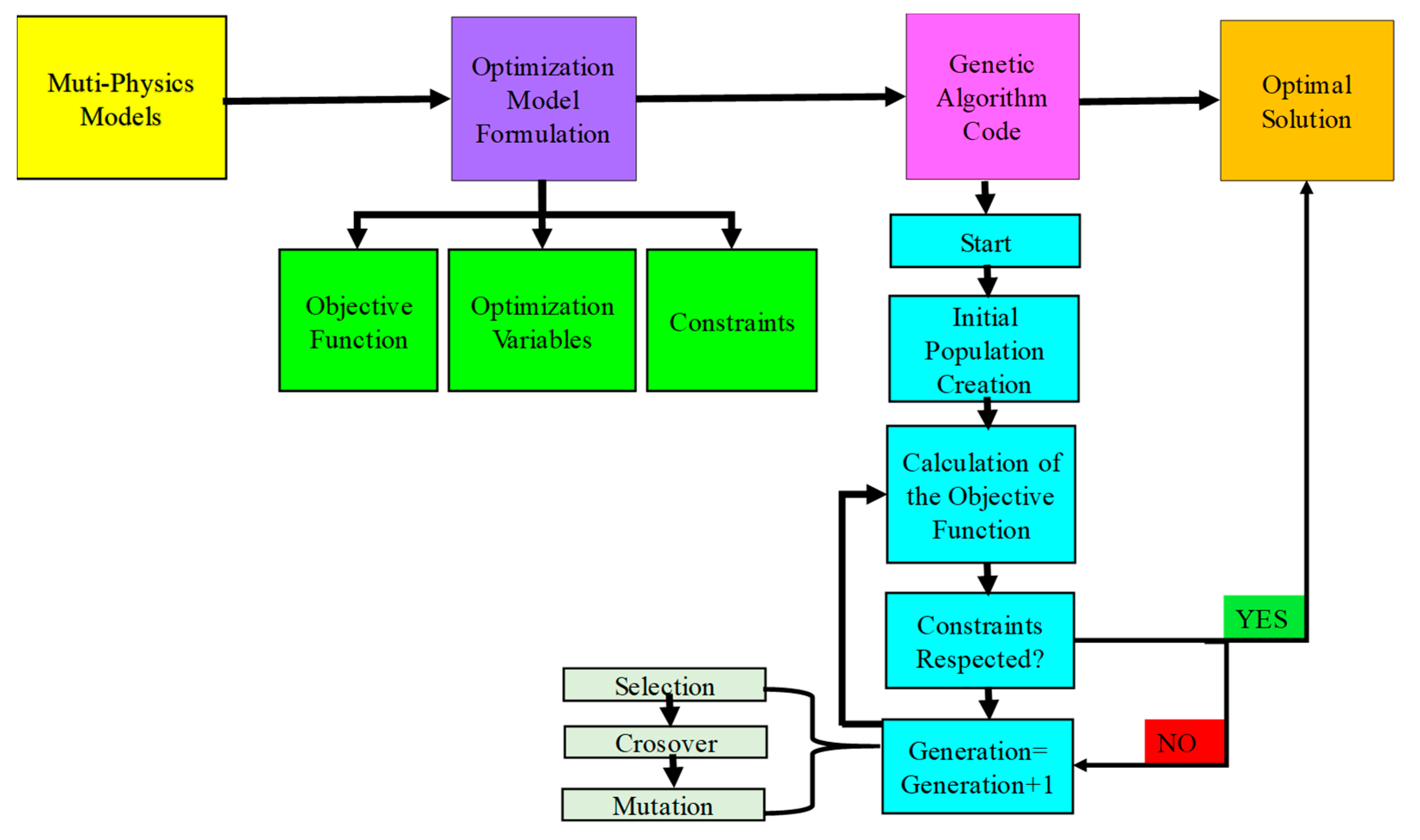
3. Design Integrated by Optimization of PMSG
3.1. Objective Function
3.2. Optimization Variables
3.3. Design Constraints
4. Design Simulation Integrated by Optimization of PMSG
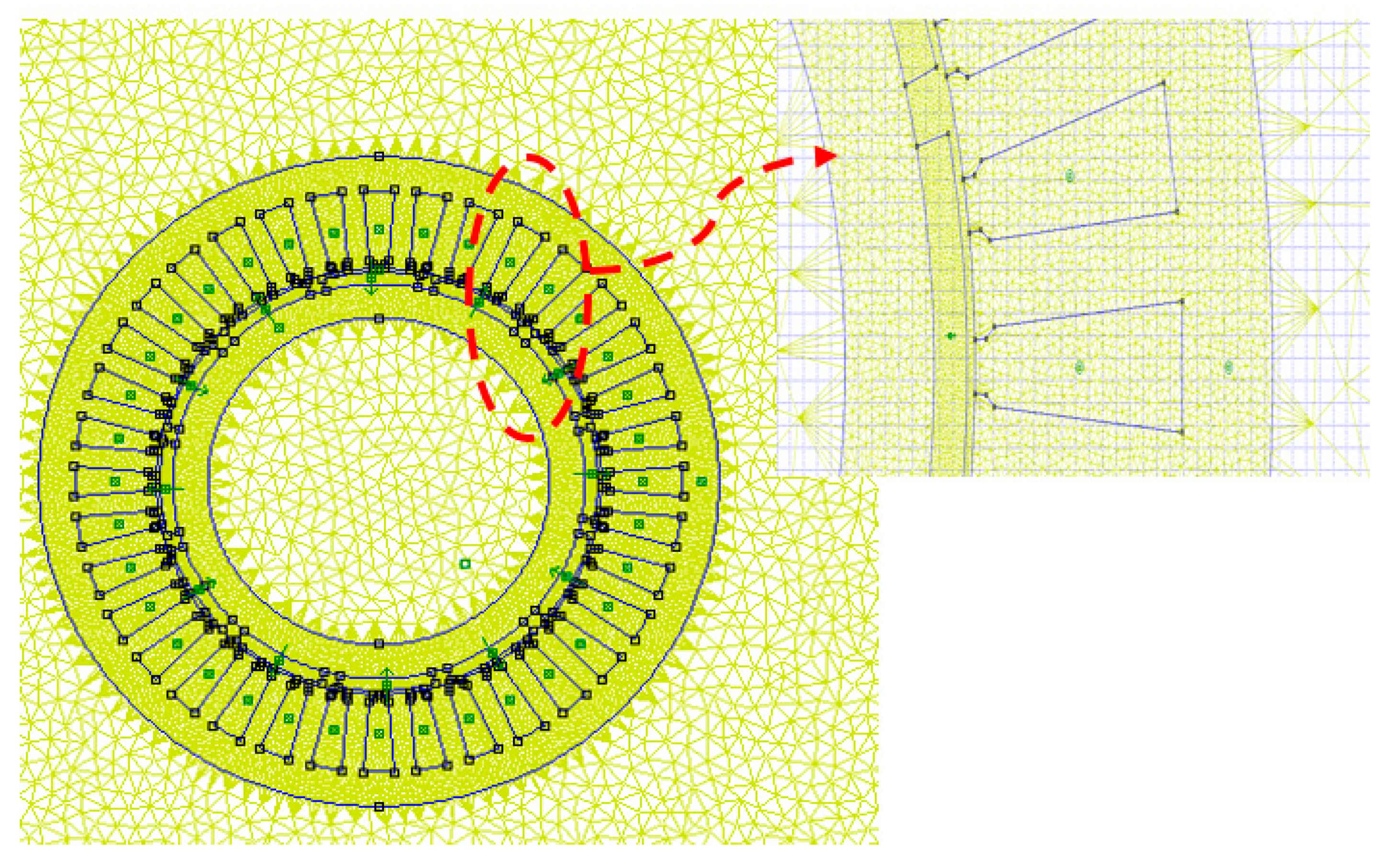
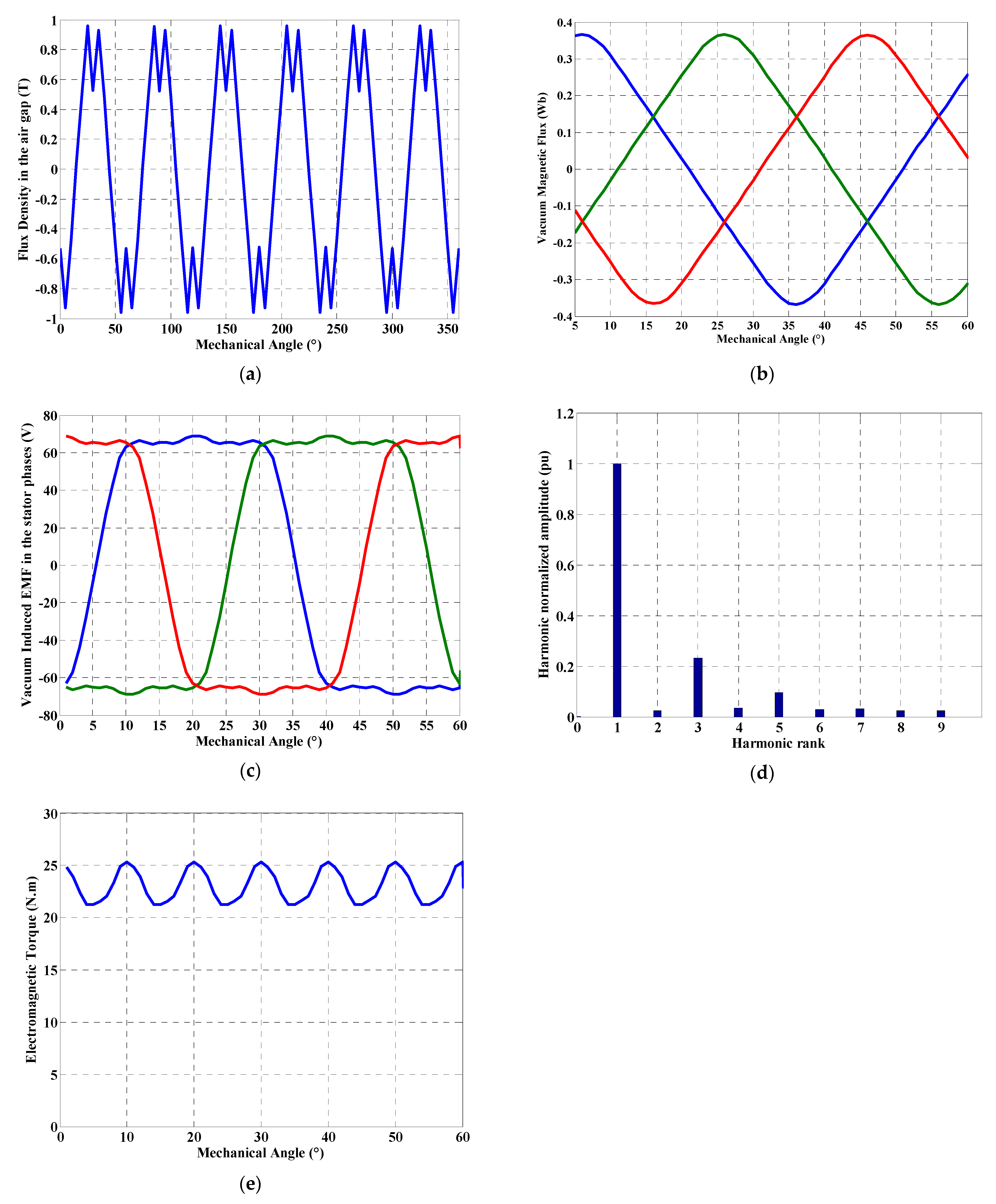
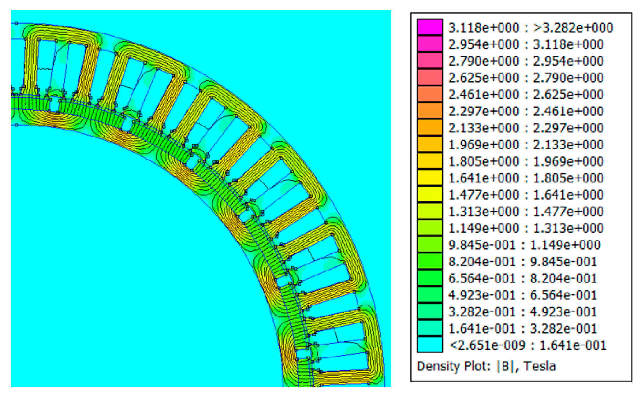
4.1. Finite Element Analysis of the Elaborated PMSG Analytical Models
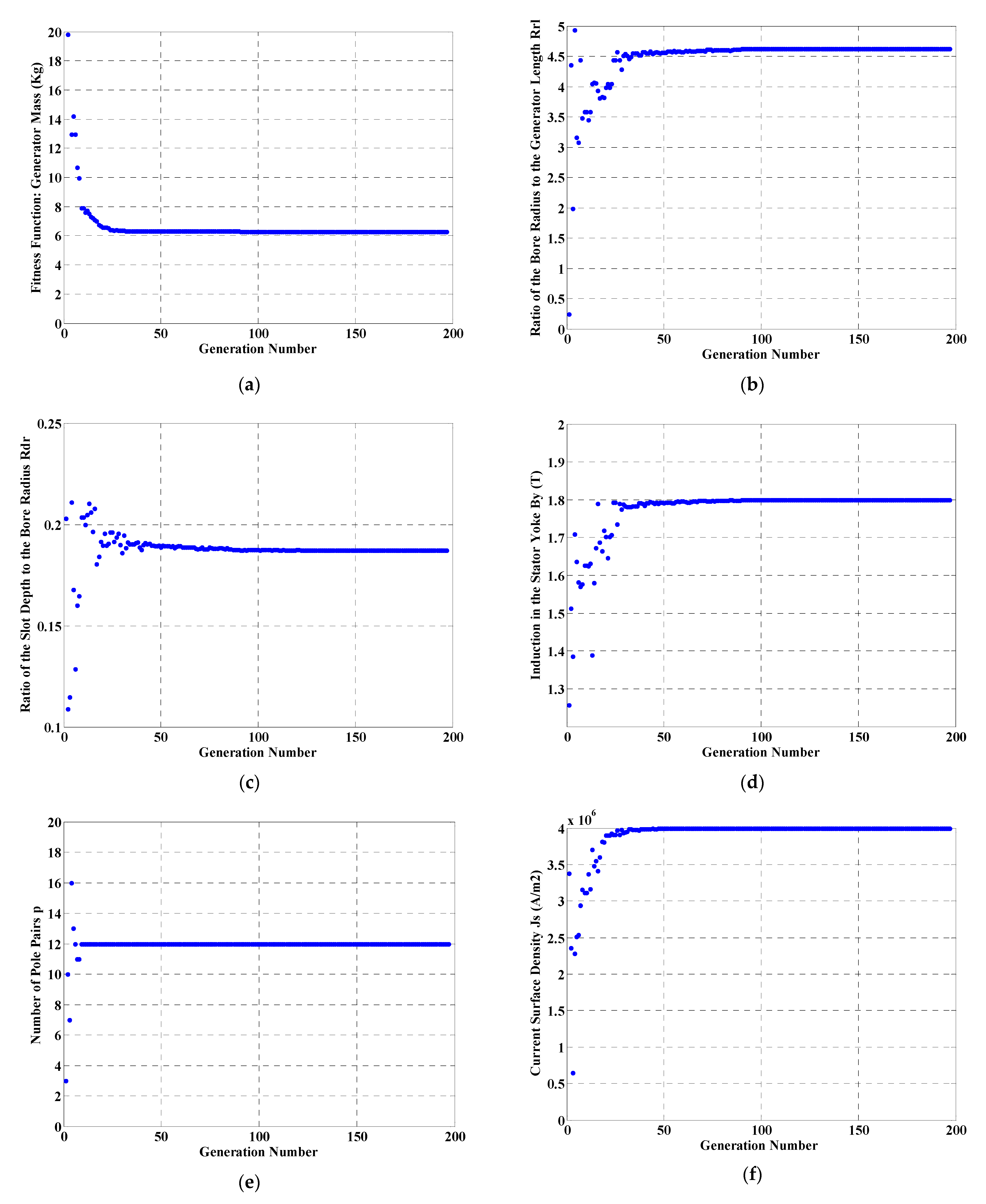
4.2. The Optimization Algorithm Simulation Results
5. Conclusions
Author Contributions
Funding
Institutional Review Board Statement
Informed Consent Statement
Data Availability Statement
Acknowledgments
Conflicts of Interest
References
- Ren, G.; Liu, J.; Wan, J.; Guo, Y.; Yu, D. Overview of wind power intermittency: Impacts, measurements, and mitigation solutions. Appl. Energy 2017, 204, 47–65. [Google Scholar] [CrossRef]
- Dai, J.; Yang, X.; Wen, L. Development of wind power industry in China: A comprehensive assessment. Renew. Sustain. Energy Rev. 2018, 97, 156–164. [Google Scholar] [CrossRef]
- Nazir, M.S.; Ali, N.; Bilal, M.; Iqbal, H.M. Potential environmental impacts of wind energy development: A global perspective. Curr. Opin. Environ. Sci. Health 2020, 13, 85–90. [Google Scholar] [CrossRef]
- Anup, K.; Whale, J.; Urmee, T. Urban wind conditions and small wind turbines in the built environment: A review. Renew. Energy 2019, 131, 268–283. [Google Scholar]
- Ram, K.R.; Lal, S.P.; Ahmed, M.R. Design and optimization of airfoils and a 20 kW wind turbine using multi-objective genetic algorithm and HARP_Opt code. Renew. Energy 2019, 144, 56–67. [Google Scholar] [CrossRef]
- Akinyele, D. Techno-economic design and performance analysis of nanogrid systems for households in energy-poor villages. Sustain. Cities Soc. 2017, 34, 335–357. [Google Scholar] [CrossRef]
- Papi, F.; Nocentini, A.; Ferrara, G.; Bianchini, A. On the Use of Modern Engineering Codes for Designing a Small Wind Turbine: An Annotated Case Study. Energies 2021, 14, 1013. [Google Scholar] [CrossRef]
- Torres-Madroñero, J.L.; Alvarez-Montoya, J.; Restrepo-Montoya, D.; Tamayo-Avendaño, J.M.; Nieto-Londoño, C.; Sierra-Pérez, J.J.E. Technological and Operational Aspects That Limit Small Wind Turbines Performance. Energies 2020, 13, 6123. [Google Scholar] [CrossRef]
- Rodriguez-Hernandez, O.; Martinez, M.; Lopez-Villalobos, C.; Garcia, H.; Campos-Amezcua, R.J.E. Techno-economic feasibility study of small wind turbines in the Valley of Mexico metropolitan area. Energies 2019, 12, 890. [Google Scholar] [CrossRef] [Green Version]
- Khojasteh, H.; Noorollahi, Y.; Tahani, M.; Masdari, M.J.I. Optimization of Power and Levelized Cost for Shrouded Small Wind Turbine. Inventions 2020, 5, 59. [Google Scholar] [CrossRef]
- Ehyaei, M.; Ahmadi, A.; Rosen, M.A. Energy, exergy, economic and advanced and extended exergy analyses of a wind turbine. Energy Convers. Manag. 2019, 183, 369–381. [Google Scholar] [CrossRef]
- Chagas, C.C.M.; Pereira, M.G.; Rosa, L.P.; da Silva, N.F.; Freitas, M.A.V.; Hunt, J.D. From megawatts to kilowatts: A review of small wind turbine applications, lessons from the US to Brazil. Sustainability 2020, 12, 2760. [Google Scholar] [CrossRef] [Green Version]
- Olatayo, K.I.; Wichers, J.H.; Stoker, P.W. Energy and economic performance of small wind energy systems under different climatic conditions of South Africa. Renew. Sustain. Energy Rev. 2018, 98, 376–392. [Google Scholar] [CrossRef]
- Hemmati, R. Technical and economic analysis of home energy management system incorporating small-scale wind turbine and battery energy storage system. J. Clean. Prod. 2017, 159, 106–118. [Google Scholar] [CrossRef]
- Bazzo, T.d.P.M.; Kölzer, J.F.; Carlson, R.; Wurtz, F.; Gerbaud, L. Multiphysics design optimization of a permanent magnet synchronous generator. IEEE Trans. Ind. Electron. 2017, 64, 9815–9823. [Google Scholar] [CrossRef]
- Shen, Y.; Zhu, Z. Analysis of electromagnetic performance of Halbach PM brushless machines having mixed grade and unequal height of magnets. IEEE Trans. Magn. 2012, 49, 1461–1469. [Google Scholar] [CrossRef]
- Gardner, M.C.; Jack, B.E.; Johnson, M.; Toliyat, H.A. Comparison of surface mounted permanent magnet coaxial radial flux magnetic gears independently optimized for volume, cost, and mass. IEEE Trans. Ind. Appl. 2018, 54, 2237–2245. [Google Scholar] [CrossRef]
- Satpathy, A.S.; Kastha, D.; Kishore, N. Vienna Rectifier Fed Squirrel Cage Induction Generator based Stand-alone Wind Energy Conversion System. IEEE Trans. Power Electron. 2021, 36, 10186–10198. [Google Scholar] [CrossRef]
- da Silva Santos, M.; Barros, L.S. Offshore wind energy conversion system based on squirrel cage induction generator connected to the grid by VSC-HVDC link. In Proceedings of the 2019 IEEE PES Innovative Smart Grid Technologies Conference-Latin America (ISGT Latin America), Gramado, Brazil, 15–18 September 2019; pp. 1–6. [Google Scholar]
- Zhang, J.; Cui, M.; He, Y. Robustness and adaptability analysis for equivalent model of doubly fed induction generator wind farm using measured data. Appl. Energy 2020, 261, 114362. [Google Scholar] [CrossRef]
- Mazouz, F.; Belkacem, S.; Colak, I.; Drid, S.; Harbouche, Y. Adaptive direct power control for double fed induction generator used in wind turbine. Int. J. Electr. Power Energy Syst. 2020, 114, 105395. [Google Scholar] [CrossRef]
- Ahmad, G.; Amin, U. Design, construction and study of small scale vertical axis wind turbine based on a magnetically levitated axial flux permanent magnet generator. Renew. Energy 2017, 101, 286–292. [Google Scholar] [CrossRef]
- Vaimann, T.; Kudrjavtsev, O.; Kilk, A.; Kallaste, A.; Rassolkin, A. Design and prototyping of directly driven outer rotor permanent magnet generator for small scale wind turbines. Adv. Electr. Electron. Eng. 2018, 16, 271–278. [Google Scholar] [CrossRef]
- Zhao, X.; Niu, S.; Fu, W. Sensitivity analysis and design optimization of a new hybrid-excited dual-PM generator with relieving-DC-saturation structure for stand-alone wind power generation. IEEE Trans. Magn. 2019, 56, 1–5. [Google Scholar] [CrossRef]
- Sindhya, K.; Manninen, A.; Miettinen, K.; Pippuri, J. Design of a permanent magnet synchronous generator using interactive multiobjective optimization. IEEE Trans. Ind. Electron. 2017, 64, 9776–9783. [Google Scholar] [CrossRef]
- Bramerdorfer, G.; Tapia, J.A.; Pyrhönen, J.J.; Cavagnino, A. Modern electrical machine design optimization: Techniques, trends, and best practices. IEEE Trans. Ind. Electron. 2018, 65, 7672–7684. [Google Scholar] [CrossRef]
- Öztürk, N.; Dalcalı, A.; Celik, E.; Sakar, S. Cogging torque reduction by optimal design of PM synchronous generator for wind turbines. Int. J. Hydrog. Energy 2017, 42, 17593–17600. [Google Scholar] [CrossRef]
- Daghigh, A.; Javadi, H.; Torkaman, H. Optimal design of coreless axial flux permanent magnet synchronous generator with reduced cost considering improved PM leakage flux model. Electr. Power Compon. Syst. 2017, 45, 264–278. [Google Scholar] [CrossRef]
- Abdoos, A.; Moazzen, M.E.; Ebadi, A. Optimal Design of a Radial-Flux Permanent Magnet Generator with Outer-Rotor for Direct-Drive Wind Turbines. Comput. Intell. Electr. Eng. 2020, 11, 51–64. [Google Scholar]
- Lei, G.; Zhu, J.; Guo, Y.; Liu, C.; Ma, B. A review of design optimization methods for electrical machines. Energies 2017, 10, 1962. [Google Scholar] [CrossRef] [Green Version]
- Mahmouditabar, F.; Vahedi, A.; Mosavi, M.R.; Bafghi, M.H. Sensitivity analysis and multiobjective design optimization of flux switching permanent magnet motor using MLP-ANN modeling and NSGA-II algorithm. Int. Trans. Electr. Energy Syst. 2020, 30, e12511. [Google Scholar] [CrossRef]
- Faiz, J.; Ebrahimi, B.M.; Rajabi-Sebdani, M.; Khan, A. Optimal design of permanent magnet synchronous generator for wind energy conversion considering annual energy input and magnet volume. In Proceedings of the 2009 International Conference on Sustainable Power Generation and Supply, Nanjing, China, 6–7 April 2009; pp. 1–6. [Google Scholar]
- Syahputra, R. Distribution network optimization based on genetic algorithm. J. Electr. Technol. UMY 2017, 1, 1–9. [Google Scholar] [CrossRef] [Green Version]
- Wrobel, K.; Tomczewski, K.; Sliwinski, A.; Tomczewski, A.J.E. Optimization of a Small Wind Power Plant for Annual Wind Speed Distribution. Energies 2021, 14, 1587. [Google Scholar] [CrossRef]
- Palmieri, M.; Bozzella, S.; Cascella, G.L.; Bronzini, M.; Torresi, M.; Cupertino, F.J.E. Wind Micro-Turbine Networks for Urban Areas: Optimal Design and Power Scalability of Permanent Magnet Generators. Energies 2018, 11, 2759. [Google Scholar] [CrossRef] [Green Version]
- Zhao, B.; Li, H.; Wang, M.; Chen, Y.; Liu, S.; Yang, D.; Yang, C.; Hu, Y.; Chen, Z.J.E. An optimal reactive power control strategy for a DFIG-based wind farm to damp the sub-synchronous oscillation of a power system. Energies 2014, 7, 3086–3103. [Google Scholar] [CrossRef] [Green Version]
- Dogan, H. Méthodologie de Conception des Machines Synchrones à Aimants. Application au Véhicule éLectrique Avec Chargeur Rapide Embarqué. Ph.D. Dissertation, Université de Grenoble, Grenoble, France, 2013. [Google Scholar]
- Lee, J.H.; Song, J.-Y.; Kim, D.-W.; Kim, J.-W.; Kim, Y.-J.; Jung, S.-Y. Particle swarm optimization algorithm with intelligent particle number control for optimal design of electric machines. IEEE Trans. Ind. Electron. 2017, 65, 1791–1798. [Google Scholar] [CrossRef]
- Tran, D.H. Conception Optimale Intégrée d’une Chaîne Éolienne “Passive”: Analyse de Robustesse, Validation Expérimentale; Institut National Polytechnique de Toulouse-INPT: Toulouse, France, 2010. [Google Scholar]
- Abdelli, A. Optimal design of an interior permanent magnet synchronous motor for wide constant-power region operation: Considering thermal and electromagnetic aspects. SAE Int. J. Altern. Powertrains 2014, 3, 129–138. [Google Scholar] [CrossRef]
- Tran, D.H.; Sareni, B.; Roboam, X.; Bru, E.; Andrade, A.D. Robust design of a passive wind turbine system. COMPEL: Int J Comput. Maths. Electr. Electron. Eng. 2012, 31, 932–944. [Google Scholar] [CrossRef] [Green Version]
- Kumaravelu, U.D.; Mohamed Yakub, S.J.M.; Engineering, S. Simulation of outer rotor permanent magnet brushless DC motor using finite element method for torque improvement. Model. Simul. Eng 2012, 2012, 961212. [Google Scholar] [CrossRef] [Green Version]
- Gerber, S. A Finite Element Based Optimisation Tool for Electrical Machines; University of Stellenbosch: Stellenbosch, South Africa, 2011. [Google Scholar]
- Ling, J.M.; Nur, T.J. Influence of edge slotting of magnet pole with fixed slot opening width on the cogging torque in inset permanent magnet synchronous machine. Adv. Mech. Eng. 2016, 8, 1687814016659598. [Google Scholar] [CrossRef] [Green Version]
- Hemeida, A.; Sergeant, P.; Rasekh, A.; Vansompel, H.; Vierendeels, J. An optimal design of a 5MW AFPMSM for wind turbine applications using analytical model. In Proceedings of the 2016 XXII International Conference on Electrical Machines (ICEM), Lausanne, Switzerland, 4–7 September 2016; pp. 1290–1297. [Google Scholar]
- Bazzo, T.P.M. Conception Optimale Multidisciplinaire de Générateurs Synchrones à Aimants Permanents Pour Éoliennes Tenant Compte de la Courbe D’occurrence du Vent; Universidade Federal de Santa Catarina: Florianópolis, Brazil, 2017. [Google Scholar]


| Optimization Variables | Symbol | Unit | Type | Range |
|---|---|---|---|---|
| Ration of the slot depth to the bore radius of the machine | _ | Continuous | [0.03, 3] | |
| Ratio of the bore radius to the active length of the machine | _ | Continuous | [0.1, 5] | |
| Pole pairs number | P | _ | Discrete | [1, …, 30] |
| Current surface density | A/mm2 | Continuous | [0.5, 4] | |
| Slot number per pole and per phase | _ | Discrete | [1, …, 5] | |
| Rated power | W | Continuous | [300, 3000] | |
| Rated angular rotation speed | rad/s | Continuous | [25, 95] | |
| Induction in the stator yoke | T | Continuous | [1.2, 1.8] |
| Parameters | Symbol | Unit | Value |
|---|---|---|---|
| Ratio of the slot depth to the bore radius of the machine | _ | 0.366 | |
| Ratio of the bore radius to the active length of the machine | _ | 2.025 | |
| Pole pairs number | P | _ | 6 |
| Current surface density | A/mm2 | 2.7 | |
| Slot number per pole and per phase | _ | 1 | |
| Rated power | W | 1100 | |
| Rated angular rotation speed | rad/s | 40 | |
| Induction in the stator yoke | T | 1.4 |
| Parameters | Symbol | Unit | Analytical Value | Numerical Value | Error (%) |
|---|---|---|---|---|---|
| Induction | T | 0.85 | 0.90 | 6 | |
| Maximum Vacuum-Induced Flux | Wb | 0.34 | 0.35 | 2.90 | |
| Maximum Vacuum-Induced EMF | V | 82.50 | 65.50 | 26 | |
| Electromagnetic Torque | N·m | 27.50 | 23.50 | 17 |
| Parameters | Symbol | Unit | Value | |
|---|---|---|---|---|
| Initial Design | Optimized Design | |||
| Bore radius | mm | 83.16 | 121.23 | |
| Active length of the generator | mm | 41.06 | 26.19 | |
| Total length of the generator | mm | 144.10 | 95.90 | |
| Stator depth yoke | mm | 11.29 | 6.40 | |
| Rotor depth yoke | mm | 11.29 | 6.40 | |
| Slot depth | mm | 30.43 | 22.71 | |
| Slot width | mm | 9.67 | 7.05 | |
| Tooth width | mm | 9.67 | 7.05 | |
| Magnet thickness | mm | 4.93 | 4.91 | |
| Air gap thickness | g | mm | 1.17 | 1.16 |
| Magnet angular width per pole | mm | 36.28 | 26.44 | |
| Number of conductors per slot | _ | 47 | 35 | |
| Number of pole pairs | p | _ | 6 | 12 |
| Maximum vacuum-induced flux | Wb | 0.34 | 0.23 | |
| Maximum vacuum-induced EMF | V | 82.55 | 78 | |
| Induced current | A | 4.44 | 4.8 | |
| Phase synchronous inductance | mH | 5.25 | 3.43 | |
| Phase synchronous resistance | Ω | 0.51 | 0.72 | |
| System Active Part | Initial Mass (kg) | Initial Cost (€) | Optimized Mass (kg) | New Cost (€) |
|---|---|---|---|---|
| Copper | 2.43 | 13.87 | 1.66 | 9.47 |
| Iron | 7.58 | 0.77 | 4.06 | 0.41 |
| Magnet (NdFeB) | 0.59 | 36.58 | 0.54 | 33.48 |
| Generator | 10.6 | 51.22 | 6.26 | 43.36 |
Publisher’s Note: MDPI stays neutral with regard to jurisdictional claims in published maps and institutional affiliations. |
© 2021 by the authors. Licensee MDPI, Basel, Switzerland. This article is an open access article distributed under the terms and conditions of the Creative Commons Attribution (CC BY) license (https://creativecommons.org/licenses/by/4.0/).
Share and Cite
Agrebi, H.Z.; Benhadj, N.; Chaieb, M.; Sher, F.; Amami, R.; Neji, R.; Mansfield, N. Integrated Optimal Design of Permanent Magnet Synchronous Generator for Smart Wind Turbine Using Genetic Algorithm. Energies 2021, 14, 4642. https://doi.org/10.3390/en14154642
Agrebi HZ, Benhadj N, Chaieb M, Sher F, Amami R, Neji R, Mansfield N. Integrated Optimal Design of Permanent Magnet Synchronous Generator for Smart Wind Turbine Using Genetic Algorithm. Energies. 2021; 14(15):4642. https://doi.org/10.3390/en14154642
Chicago/Turabian StyleAgrebi, Henda Zorgani, Naourez Benhadj, Mohamed Chaieb, Farooq Sher, Roua Amami, Rafik Neji, and Neil Mansfield. 2021. "Integrated Optimal Design of Permanent Magnet Synchronous Generator for Smart Wind Turbine Using Genetic Algorithm" Energies 14, no. 15: 4642. https://doi.org/10.3390/en14154642