Article

Hydrogen Injection in a Dual Fuel Engine Fueled with Low-Pressure Injection of Methyl Ester of Thevetia Peruviana (METP) for Diesel Engine Maintenance Application

1
Department of Mechanical Engineering, SDM College of Engineering and Technology, Dharwad, Karnataka 580002, India
2
Department of Mechanical Engineering, B.V.B. College of Engineering and Technology KLE Technological University, BVB College Campus, Hubli, Karnataka 580021, India
3
Department of Mechanical Engineering, P.E.S. Institute of Technology and Management, Shivamogga 577204, India
4
Department of Mechanical Engineering, Faculty of Mechanical Engineering, University of Malaya, Kuala Lumpur 50603, Malaysia
5
Ingenium Research Group, University of Castilla-La Mancha, Ciudad Real 13071, Spain
6
Modeling Evolutionary Algorithms Simulation and Artificial Intelligence, Faculty of Electrical & Electronics Engineering, Ton Duc Thang University, Ho Chi Minh City 758307, Vietnam
7
Department of Mechanical Engineering, Jain College of Engineering, Belagavi Karnataka 590014, India
8
Research Center for Advanced Materials Science (RCAMS), King Khalid University, P.O. Box 9004, Abha 61413, Asir, Saudi Arabia
9
P. A. College of Engineering (Affiliated to Visvesvaraya Technological University, Belagavi), Mangalore 574153, India
10
Department of Mechanical Engineering, Benha Faculty of Engineering, Benha University, 13512 Benha, Qalubia, Egypt
*
Author to whom correspondence should be addressed.
Energies 2020, 13(21), 5663; https://doi.org/10.3390/en13215663
Submission received: 31 July 2020 / Revised: 16 October 2020 / Accepted: 22 October 2020 / Published: 29 October 2020
(This article belongs to the Special Issue Advances in Maintenance Management)

Abstract

:
The present work is mapped to scrutinize the consequence of biodiesel and gaseous fuel properties, and their impact on compression-ignition (CI) engine combustion and emission characteristics in single and dual fuel operation. Biodiesel prepared from non-edible oil source derived from Thevetia peruviana belonging to the plant family of Apocynaceaeis. The fuel has been referred as methyl ester of Thevetia peruviana (METP) and adopted as pilot fuel for the effective combustion of compressed gaseous fuel of hydrogen. This investigation is an effort to augment the engine performance of a biodiesel-gaseous fueled diesel engine operated under varied engine parameters. Subsequently, consequences of gas flow rate, injection timing, gas entry type, and manifold gas injection on the modified dual-fuel engine using conventional mechanical fuel injections (CMFIS) for optimum engine performance were investigated. Fuel consumption, CO, UHC, and smoke formations are spotted to be less besides higher NOx emissions compared to CMFIS operation. The fuel burning features such as ignition delay, burning interval, and variation of pressure and heat release rates with crank angle are scrutinized and compared with base fuel. Sustained research in this direction can convey practical engine technology, concerning fuel combinations in the dual fuel mode, paving the way to alternatives which counter the continued fossil fuel utilization that has detrimental impacts on the climate.

1. Introduction

Brake thermal efficiency, fuel consumption, power, consistency, and robustness of compression ignition (CI) engines are more than their counterpart petrol engines. Hence, they are well accepted for applications related to sectors of power, transport, and agriculture. Achieving improved conservation of energy with high brake thermal efficiency associated with lower emissions are given prime importance, and they are imperative for engine design and development [1,2]. Diesel engines operate on a wide range of alternative and renewable fuels (biodiesels, alcohols, and gases like Compressed Natural Gas (CNG), hydrogen, producer gas, and biogas) [3]. Researchers have explored these alternatives to conventional fuel from the perspective of lowering oil-import burdens on developing countries, heralding self-reliance through sustainable energy [4,5]. Several investigators have studied techniques to strengthen the performance of a compression-ignition (CI) engine at reduced emission levels. In this regard, natural gas exhibiting properties more similar to diesel, while operating at lower operating costs, resulting in lower emission levels to be an encouraging substitute to diesel fuel. Compared to diesel, CNG has a higher specific enthalpy that establishes its energy density per unit volume to be equivalent to corresponding diesel fuel expressed per unit mass basis. The comparison between its utilization and reserves has been found to be better off as compared diesel fuel, that clearly establishes the contention to be a sustainable fuel for future [6,7]. Renewable, sustainable, and alternative fuels have several advantages that include environmental benignity, conservative foreign exchange usage, and arrest socio-economic anxieties [8,9,10]. Fossil fuels are primary energy sources, but they are depleting in nature, and combustion of such fuels for power generation, resulting in hazardous environmental degradation. The higher standards of living, urbanization besides socio-economic development around the globe have worsened the environmental conditions, leading to epidemically poor air quality. There is an urgent need to look into the issues caused by the burning of fossil fuels.
In this context, energy from renewable and sustainable fuels seems to be better for achieving the improved economy of any nation and standard of life [11,12]. Therefore, the utilization of biomass-derived fuels like biodiesel, biogas, hydrogen, producer gas, etc., dramatically contributes to sustainable waste management systems to eliminate or reduce the use of fossil fuels [13]. Energy management with high efficiency and lesser emission is significant for country development [14,15,16]. The government of India has been put into practice for the biomass power/co-generation program. In general, overall, approximately 500 projects on biomass-based power generation and cogeneration collecting to 4760 MW capability have been already established in India for maintaining power to the network. In India, the possibility of biomass is anticipated at almost 500 million metric tons annually. Studies showed that the Ministry had assessed additional biomass accessibility at about 120–150 million metric tons per annum, including both farming and forestry remainders corresponding to about 18,000 MW. Additionally, about 7000 MW added power could be created using waste bagasse-based cogeneration. This status indicates there is a tremendous amount of potential for harnessing energy from such renewable sources of energy. Hence, in the present energy scenario, power generation through biomass-derived fuels is of utmost importance. Power generation through the integrated gasifier-engine system using waste biomass or pallets/briquettes is necessary. To harness plenty of power through such devices, highly efficient power generation equipment’s production and skilled person’s development are essential [17,18,19]. Use of gaseous fuels such as compressed natural gas and hydrogenated compressed natural gas (HCNG) in a diesel engine is more attractive fuels [7,20,21]. Maximum energy from the natural gas can be harnessed when it is mixed with hydrogen; thereby, its flame speed further increased and leads to better and faster combustion.
Das et al. [22] addressed development of hydrogen-powered CI engines. They have described the method of using hydrogen in diesel engines and addressed its advantages and disadvantages. Further, they have studied objectionable burning trends such as backfire, pre-ignition, knocking, and speedy pressure rise rate. In their work, an innovative and revolutionary viewpoint of the utilization of hydrogen in CI engines has been demonstrated gas operated diesel engines on dual fuel mode suffers from poor utilization of the gaseous fuel during combustion at lower and intermediate loads. Hence, they result in poor engine performance and emissions [23]. However, at higher loads, gaseous fuel performs better, leading to improved gaseous fuel utilization, engine performance, and higher CO level were observed in comparison with normal diesel operation [20,24,25,26]. Researchers have reported values of 20% to 30% higher thermal efficiency with the addition of hydrogen. This could be due to the increased flame speed of HCNG caused by the addition of Hydrogen, and hence the equivalence ratio is considerably greater than the stoichiometric situation, and distinct the burning of methane is not as steady as with a combination of H2-CNG [27]. Higher CO intensity under dual fuel mode has been described contrasted to normal diesel function styles even at higher loads, which signaled some flame extinction zones to exist [28,29]. High flame speed of hydrogen exists over an ample variety of temperatures and pressures, and higher flame speed causes an increase in the rate of pressure rise and combustion. The stratified combination procedure can be utilized to combust a lean combination when it is lesser than the lesser flammability limit of hydrogen. Hydrogen managed engines can have a durable and permanent flow of hydrogen without throttling as gaseous hydrogen has wide flammability [23,30,31,32,33,34]. The impact of injection timing, injection interval, and hydrogen substance on the burning aspects of a CI engine employed in the dual-fuel approach applying diesel and hydrogen manifold injection has been described. Engine function at the optimum start of injection at gas exchange Top Dead Centre (TDC) with an injection period of 30 °CA for an H2 flow rate of 7.5 lpm caused superior performance with appropriate levels of emission intensities [35,36,37,38]. Dimitriou et al. [39] investigated the hydrogen on the combustion of diesel-powered diesel engines functioned on a dual fuel approach. They have achieved a hydrogen energy share of up to 98% at low load operation. They observed that the carbon-based and NOx formation were dropped and 85% reduced soot level associated with the conventional diesel operation. They found increased NOx level at medium load and claimed that this may be due to high energy content of hydrogen. Serrano et al. [40] addressed energy efficiency enhancement and emissions reduction techniques by utilizing hydrogen in a diesel engine. They have studied engine operation at two velocities and numerous injection approaches. They have also addressed self-ignition, combustion knocking, and water was an injection in the intake manifold to reduce the NOx intensity. Increased NOx and smoke formations have been described with heightened hydrogen proportion. However, 30% of water injection resulted in 37% efficiency and lowered NOx emissions. Khan et al. [41] scrutinized the performance and emission qualities of a CI engine functioned on a dual fuel mode employing a B20 combination and analyzed the influence of injection pressure and hydrogen injection (15 lpm). They have operated the engine on dual fuel mode. They have diverged the injection pressure from 200 to 240 bar in steps of 20. They found minimum Specific Fuel Consumption (SFC) and maximum ηth with lowered emission concentrations at optimum injection pressure associated to the operation with other blends and injection pressures. Koten et al. [42] examined the influence of hydrogen on the performance and emissions of four cylinders, a water-cooled diesel engine. They have added hydrogen with air in the intake manifold, and hydrogen was used at various proportions (0.20, 0.40, 0.60, and 0.80 lpm). The researchers have reported on engine performance characteristics at varying loads under a constant 1800 rpm operation. It observed an increase in the exhaust gas temperature and NOx emissions at the addition of 0.80 lpm hydrogen and higher loads. With hydrogen addition, emissions levels such as smoke, HC, and CO were decreased with growing in NOx level. Liew et al. [43] observed an increase in the peak cyl pr. and the peak HRR when greater hydrogen was combined at high load. They observed a three-stage combustion process for the diesel–hydrogen operated dual-fuel engine associated with diesel engines two-stage burning development. Due to fuel diffusion combustion and the premixed hydrogen burning, multiple turbulent flames were developed, leading to amplified peak heat release. No change has been noticed when greater hydrogen was added at a low load. The use of hydrogen resulted in greater power to weight ratio associated with diesel-fueled function. However, it resulted in peak power and was found to be approximately 14% greater. For ensuring satisfactory combustion, they have adopted inlet air heating for the hydrogen-fueled engine, which in turn resulted in a greater peak in-cylinder pressure [43]. Exergy analysis has been carried out by [44]. The study revealed that available work at rated load increased from 29% to 32%. Reduction in irreversibility and lowered intensive entropy generation during combustion was reported to be the reason. Rakopoulos and Kyritsis [45] analyzed the second law of thermodynamics concerning hydrogen-fueled engines. They observed differences in the irreversibility generation during combustion between hydrogen and hydrocarbons. Entropy generation during the oxidation reaction of the two fuels is accountable for the remarked manner. They noticed that decreased burning irreversibility when hydrogen content was increased. Increased second law efficiency has been reported with increased hydrogen. Tarkanand Karagöz [46] studied diesel–hydrogen burning in a CI engine. They found a reduction in the indicated thermal efficiency and increased indicated specific fuel consumption when hydrogen energy fraction was increased. As far as emission concentrations were involved, smoke, CO, and CO2 were decreased with enlarging hydrogen proportion. At the 16% hydrogen energy fraction, no change in NOx formation has been reported. Loganathan and Velmurugan [47] modified the conventional diesel engine to operate on gas. They supplied hydrogen with exhaust gas recirculation through the intake. They injected hydrogen at an injection pressure of 2 bar with 2, 4, 6, 8 and 10 L/min. Combustion characteristics of an engine such as ignition delay, burning interval, rate of pressure rise (ROPR), heat release rate (HRR), cumulative heat release rate (CHR), and cyclic pressure fluctuations were reported. They found a decrease in the peak pressure and HRR with the expanded Exhaust Gas Recirculation (EGR) rate. Variations in cyclic pressure and the high burning period have been reported with EGR.
Reduction in combustion irreversibility was reflected in Santoso et al. [48], who investigated Brake Specific Energy Consumption (BSEC), indicated efficiency, and Cylinder Pressure (CP). They observed that the addition of hydrogen led to a reduction in the peak CP and engine efficiency. The reaction growth was fluctuating, and the burning ratio of reaction was slower, as demonstrated by the Computational Fluid Dynamics (CFD) computation [49]. Some investigators have applied a diesel engine on dual fuel mode utilizing different biodiesel and gas (Liquified Petroleum Gas (LPG), CNG, hydrogen, biogas) combinations. Further, hydrogen-enriched gases like CNG, the low calorific value like producer gas have been used in dual fuel concepts with diesel, biodiesel injection to improve the performance and emission characteristics as well.
Producer gas has a minimum calorific value that caused inadequate performance with expanded HC and CO formations. However, it created a substantial drop in smoke and NOx intensities [18,50]. In this context, researchers combined hydrogen in producer gas and introduced a combination into the cylinder employing an appropriate blending chamber. Yaliwal et al. [51] examined the impact of hydrogen in the producer gas-fueled dual-fuel engine. They integrated the hydrogen in the variety from 4–12 L/min and was introduced in the intake manifold. They detected that diminished de-rating with augmented brake thermal efficiency with lowered emission concentrations. Nevertheless, they realized an enlarge in NOx level and declined smoke, HC, and CO patterns. Nevertheless, they noticed an enlarge in the ignition delay with heightened cylinder pressure and HRR. Halewadimath et al. [52] described that the utilization of hydrogen injection in a producer gas powered diesel engine was provided an enhancement in the thermal efficiency with diminished emission quantities. In addition, they have adapted the conventional mechanical fuel injection system into common rail direct injection, and also substituted HCC into re-entrant CC (RCC). This modification additional expanded the ηth with substantial declines in emissions except for NOx formation. However, Yasin et al. [53] reported that lower heating value of hydrogen is higher than diesel fuel, but the decrease in volumetric efficiency reduced the torque and hence the power produced by the engine.
In their study, the CRDI diesel engine with RCC was run on neem oil methyl ester-hydrogen-producer gas combination and at an injection timing 10° BTDC and IP of 800 bar. They reported that BTE was increased by 3.02% and smoke, HC, and CO were diminished by 22.4%, 12.2%, 10.8%, respectively, while the NOx soared by 18.6% in comparison with the similar fuel combination with HCC. Additional, expanded cylinder pressure and HRR were remarked. The literature survey on dual fuel engine concept with biodiesel (METP) and hydrogen utilization is limited to low pressure injection of the pilot fuels selected. Further, METP was not much investigated in dual fuel concept with hydrogen dosage. Use of high-pressure injection of viscous fuels of biodiesels coupled with higher calorific value hydrogen gas is not much investigated. Hence the present work discusses the combined effect of injection of both liquid and gaseous fuels on the performance of the modified diesel engine operated in dual fuel mode and the associated feasibility studies.
Direct Injection and Port Injection use computer-controlled electric injectors to spray fuel into the engine. The difference is where they spray the fuel. Direct injection has the injectors mounted in the cylinder head and the injectors spray fuel directly into the engine cylinder. It then mixes with the air. Only air passes through the intake manifold runners and past the intake valves with direct injection. There are advantages and disadvantages of both systems. The advantages of direct injection is better fuel economy, less emissions, and better performance. Fuel economy improvements can be as much as 15%, allowing much less fuel to be wasted. It delivers fuel more precisely to increase better combustion with more power while maintaining better fuel economy and lowering emissions. A 25% emission drop at cold-start is possible. Direct injection meters the amount of fuel exactly into each cylinder for optimum performance and it’s sprayed under very high pressure, up to 15,000 PSI on some vehicles, so the fuel atomizes well and ignites almost instantly. The major drawback of direct injection is carbon buildup on the backside of the intake valves. This can throw a computer code, and could result with a ignition failure. The other disadvantage of direct injection is cost. The injector tips are mounted right into the combustion chamber, so the materials of the injector have to be very good quality. High pressure is needed to inject fuel directly into the cylinders which means expensive high-pressure fuel pumps are needed. They are typically mechanically driven from the engine, which adds to the complexity [54].
The extensive literature review mainly highlights the trial engine tests conducted on customized single cylinder, four stroke, water cooled and DI diesel engine operated on dual fuel mode with two varieties of CMFIS injection systems. The liquid fuel, such as METP, has been used as injected liquid pilot fuel with gaseous hydrogen supplied as manifold injected fuel at optimized engine parameters. The CMFIS dual-fuel engine was operated under optimum engine settings of 27° BTDC (Before Top Dead Centre), 240 bar injection pressure adopting a 5-hole injector with 0.2 mm orifice. The selection of an injector with fixed number of holes also depends on its compatibility with combustion chamber. In the present work, the injector is optimized with modified combustion chamber as well. The engine adopted re-entrant combustion chamber with dual-fuel operation on biodiesel and gaseous fuel. The engine parameters were optimized with respect to gaseous fuel flow rates, injection timing, injection duration and methods of gaseous fuel injection methodology. The use of hydrogen through injection facility in a biodiesel fueled dual fuel engine has been less investigated and reported. The presented work compares hydrogen injection and induction methods. The two fuels selected for investigations are nature based and renewable to make the initiative to be sustainable practice as it avoids use of fossil fuels. Major modification in the existing engines will require higher operating costs of the transportation. The present work helps in this direction by suitably adopting renewable energy technologies using minimum interventions in the existing diesel engine technology. Additionally, the present work suggests methods to fine tune the existing diesel engines used for the transportation sector without much burden on the cost of engine operation as well. Overall concept adopted strongly in line with the sustainable development goals envisaged by United Nation by year 2030 towards realization of eco-friendly power generation and utilization.

2. Materials and Methods

This section describes the fuels used and their properties along with the experimental setup used in the engine performance investigations.

2.1. Liquid and Gaseous Fuels Properties

In the present investigation, two fuels were utilized viz, conventional fuel, and biodiesel obtained from Thevetia peruviana (B100) termed as METP. The biodiesel obtained from Thevetia peruviana belongs to the family of Apocynaceae, which is plentifully accessible in India. This plant is native of Central and South America, but now regularly cultivated during the steamy and sub-tropical areas. It is a classic humid shrub or tiny tree that holds yellow or orange-yellow, the flowers, and its fruit is deep red/black covering a sizeable seed that carries some similarity to a Chinese lucky nut. Figure 1 indicates the fuels utilized in the CMFIS engine. The properties of fuels applied are shown in Table 1 and Table 2.
Additionally, hydrogen (H2) gas (purity 99.99%) was obtained from the BHORUKA GASES PVT.LTD., Bangalore. The hydrogen injection system has a suitable venture and is fitted inside the intake manifold to supply Hydrogen gas. The auto-ignition temperature of 858 K, flammability limits (% volume in air) of 4–75, stoichiometric air/fuel ratio on mass basis of 34.3, density at 15 °C and 1 bar (kg/m3) of 0.0838, net heating value (MJ/kg) of 119.93, and flame velocity (cm/s) of 265–325.

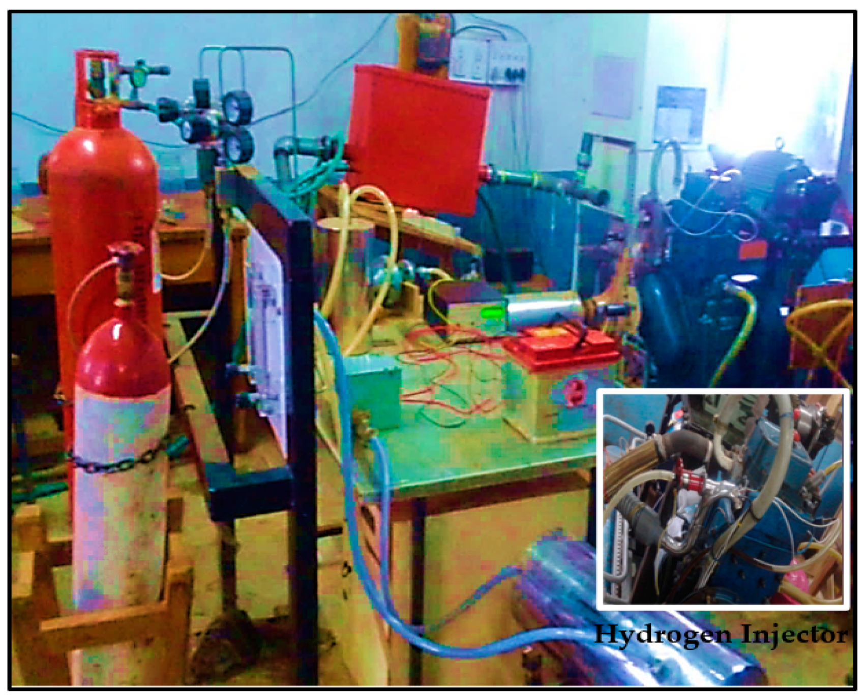
2.2. Engine Test Rig with CMFIS

Tests were performed using single cylinder, CI engine with a cylinder capacity of 660 CC, a compression ratio of 17.5, generating 5.2 kW at 1500 rpm, and its layout is indicated in Figure 2, as well as its description demonstrates in Table 3. The engine operates typically at 1500 rpm speed. The compression ratio is adjusted without impeding the engine and burning chamber geometry by specifically constructed tilting cylinder block arrangement. The setup encompasses of CI engine connected to a dynamometer for inserting and applied with numerous devices for ignitions pressure and measurements of crank angle. The signals interfaced across the engine display to the computer for P-V and P-θ diagrams. Sensors are utilized for air and fuel flow, temperatures, and load measurement. The system has a self-contained panel case covering of air case, manometer, transmitters for air and fuel flow measurements, double fuel tanks utilized for dual fuel test, fuel assessing unit, engine indicator, and process marker. Rotameters were comprised of cooling and calorimeter fluid flow measurements. The system permits compression ratio alterations for measurement of mechanical efficiency, indicated and brake thermal efficiency, volumetric efficiency, as well as brake, indicated and frictional power, Indicated Mean Effective Pressure (IMEP), Brake Mean Effective Pressure (BMEP), heat balance, A/F ratio, and specific fuel consumption. The introduction injector pressure and injection timing, as stated by the manufacturer, respectively, is 205 bar and 23° BTDC. To evaluate the impact of injection timings, static timings about 19° BTDC and 27° BTDC are utilized apart from the specified injection timing. The comprehensive examination is performed in such a manner that the performance of the engine worsens appreciably with retarded timing below 19° BTDC and advanced timing above 27° BTDC. The injection timing was maintained constant at 23° BTDC, and the compression ratio varied from 15 to 17.5. Figure 1 illustrates the layout of the testbed.
The governor is used to regulate the engine speed. The engine incorporated with the combustion chamber of hemispherical shape with overhead valves works through pushrods. Engine cooling is carried by circulating coolant through the water jackets on various components of the engine that require cooling. The pressure transducer of piezoelectric nature is installed with the surface of the cylinder head to gauge the cylinder pressure. The common rail or high-pressure collector is utilized to protect fuel at lifted pressure. Up to this, the collector volume needs to keep up the pressure changes brought by fuel pulses and conveyed by pump and fuel-injection cycles. This guarantees that, when the injector opens, infusion weight stays steady. On the other hand, the aggregator volume ought to be sufficiently massive to suit this necessity, and the other hand, it must be sufficiently little to give a fast weight increment on motor begin. Figure 2 shows the toroidal reentrant combustion chamber shape.
At the beginning of the experimentation, a consequence of EGR on the performance of METP-hydrogen fuelled dual-fuel engine with hydrogen injection using the Manifold method has been considered. The percentage of EGR was fixed at 20% for this case based on the results obtained on METP-Hydrogen dual-fuel engine operation, in which hydrogen was inducted earlier, and accordingly, the percentage of EGR was fixed at 20% for the study.

2.3. Manifold Injection System

A pressure regulator with two-stage is fitted on the Hydrogen gas cylinder that supplies hydrogen at 2 bar. Hydrogen was permitted to flow across a rotameter that is calibrated to provide an identified flow rate of the metered gas. Flashback arrester, flame arrester, and wet type flame trap were linked end to end to avoid fire hazards and induct the metered gas into the intake manifold. The hydrogen quantity rate flow rate was varied from 0.10 to 0.25 kg/h. Hydrogen is extremely inflammable, and thus a flashback arrester (acts as a non-return valve) was applied. The wet type of flame trap extinguishes any accidental flame flowing back into the gas supply side. A flame arrester is also utilized in the investigation. The hydrogen injector utilized has the terms as presented in Table 4. The engine is conducted with a pilot injection of METP whilst H2-gas was inserted in the inlet manifold and port (dual fuel mode). The flow rate of the liquid fuel is controlled spontaneously as the engine is self-governed. The flow rate of hydrogen gas is modified for the applied load safeguarding smooth engine function devoid of any knock. The hydrogen gas manifold and port injection system utilize an applicable ECU. The ECU secures the signal around the TDC arrangement across the infrared sensor to monitor the hydrogen gas injection timing. The hydrogen gas injector is a solenoid type and employs a 12 V battery for power supply.
HRR was calculated based on the first law of thermodynamics,
Q a = γ γ 1 [ P d V ] + 1 γ 1 [ V d p ] + Q w a l l
where,
  • Qa—Apparent heat release rate, J
  • V—Instantaneous volume of the cylinder (m3)
  • P—Cylinder pressure (bar)
  • Qwall—Heat transfer to the wall (J)
    Q w a l l = h × A × [ T g T w ]
  • h—Heat transfer coefficient in W/m2 K
  • T—Cylinder gas temperature in K
  • A—Instantaneous Area (m2)
The Figure 3 shows the schematic layout of the test facility adopted for the investigations on dual fuel mode operation of CI engine with Hydrogen injection. The diagram provides details of various measurement equipment for engine operation with initial conditions of injection set to TDC, 5° ATDC, 10° ATDC, 15° ATDC, and injection ON time (i.e., injection duration) of 30, 60, and 90 deg. CA for Hydrogen under optimized level. The hydrogen flow rate was adopted to be 0.25 kg/h incorporating optimum injection time for hydrogen through a series of investigative trials. Figure 4 indicates the dual-fuel engine test rig provided with hydrogen injections.

3. Results and Discussion

The salient results obtained through the extensive experimental observations have been discussed with respect to consequences of various start of injection (SOI) and injection duration (ID) for hydrogen operation under manifold injection. Facilities were established for Hydrogen injection into the engine inlet manifold as well as the port. For this, a low pressure (5 bar) solenoid hydrogen nozzle was utilized to inject hydrogen into the inlet manifold and port using an electronic control unit (ECU). Further experiments were performed on a dual-fuel engine with a pilot injection of METP at optimized injection timing of 27° BTDC, 240 bar IP, CR 17.5, and an engine speed of 1500 pm. For hydrogen SOI were kept at TDC, 5°, 10°, and 15° ATDC in both the versions of a manifold and port injection. The SOI beyond 15° ATDC resulted in engine knocking, and hence the results are not presented for this case. Hydrogen injection duration (ON time) was selected from as 30 to 90 °CA in steps of 30 °CA. The characteristics (i.e., performance, emission, and burning) of the dual-fuel engine has been investigated when fuelled with Hydrogen-Diesel/METP combination. The hydrogen flow rate was maintained at 0.25 kg/h, and METP was applied as pilot injected fuel.

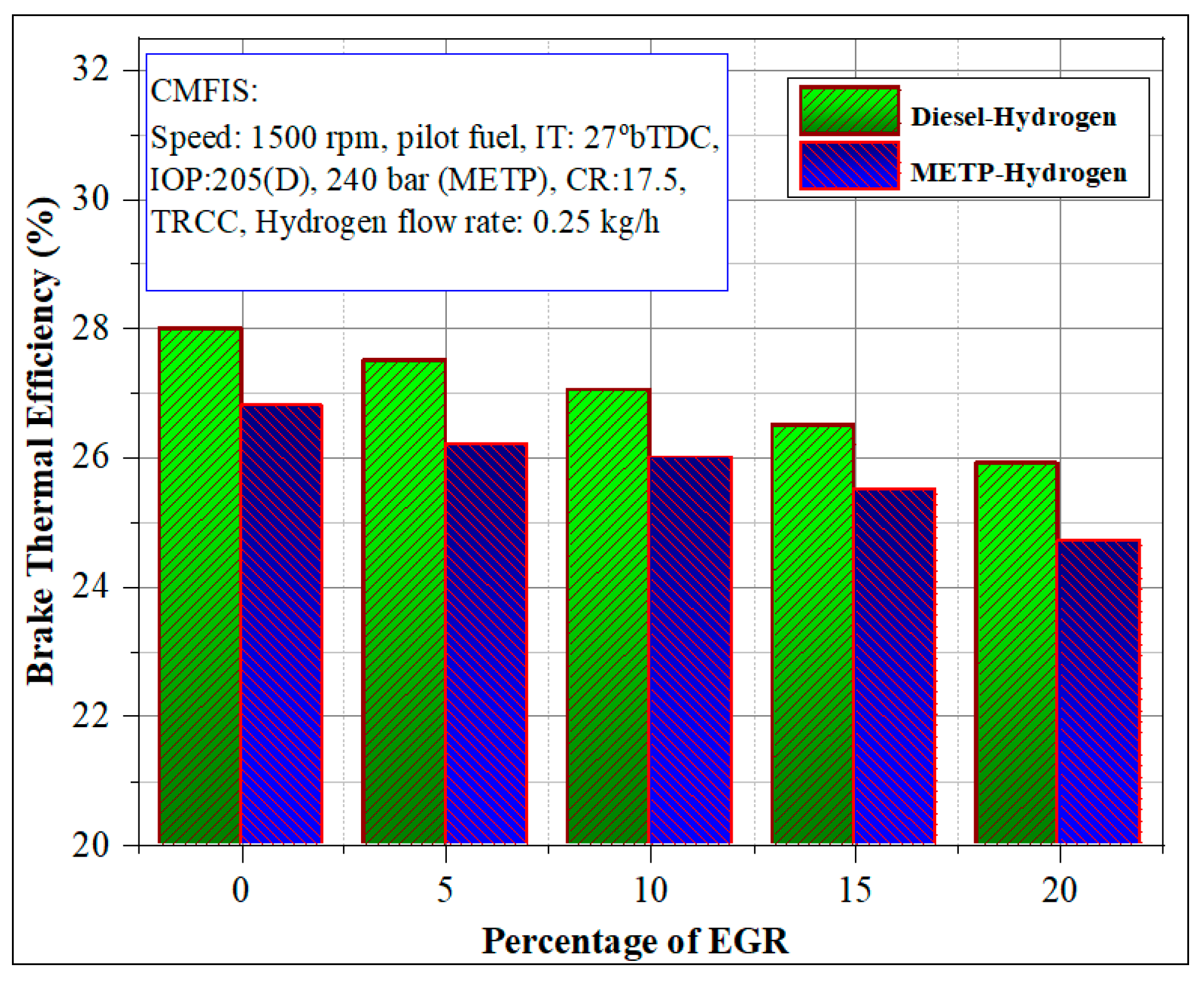
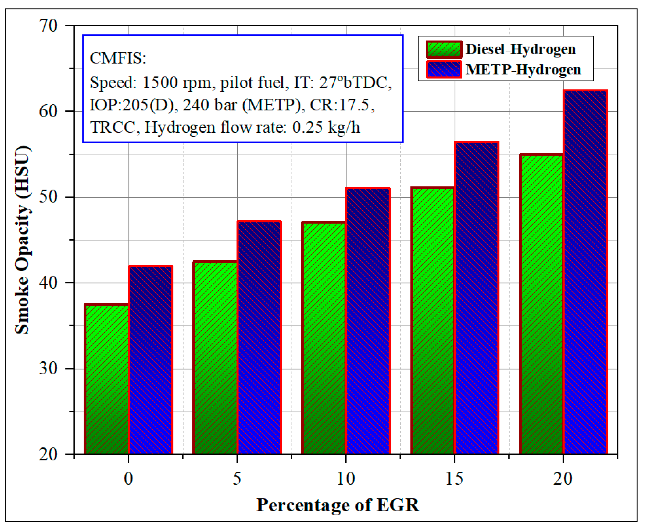
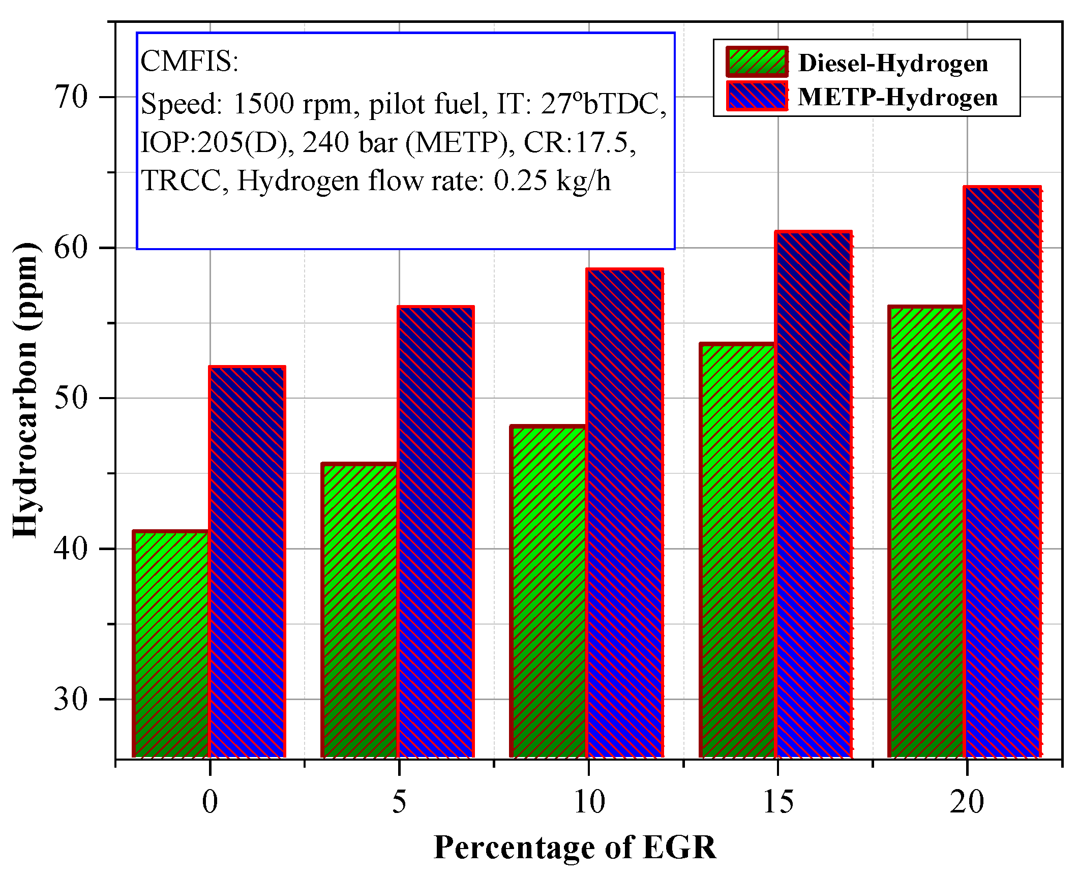
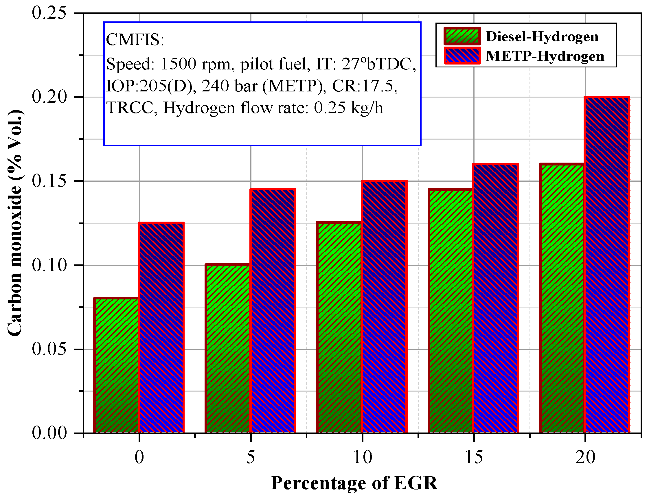
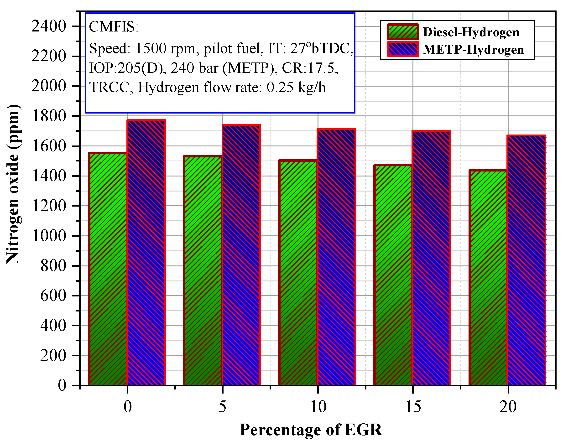
3.1. Impact of EGR on the Implementation of METP-Hydrogen-Powered Dual-Fuel Engine with Hydrogen Introduction

The effect of EGR on the ηth for Diesel/METP-hydrogen dual-fuel function is shown in Figure 5. It is evident from Figure 5 that the BTE reduces with increasing EGR rates. This could be ascribed to the fact that the mixture was diluted when burnt gas was mixed; hence it results in increased HC and CO emission levels. Additionally, drastic changes in the specific heat of a charge during compression and expansion are responsible for the results observed. The presence of EGR in the charge decreases inlet charge temperature resulting in decreased BTE. All factors mentioned and along with the thermal effect of EGR, significantly vary the combustion characteristics. Further, when part of the exhaust gas was admitted to the engine through the intake manifold, it replaces the equal amount of intake air. This leads to decreased air-fuel ration and chemical kinetics and affects the dual-fuel engine combustion negatively. Further these results into decreased BTE due to reduced volumetric efficiency.
For the same EGR rates, decreased BTE was obtained for METP-Hydrogen compared to diesel–hydrogen. For the similar injected fuel during dual fuel process hydrogen injection, improved performance has been observed. This may be due to the higher flame velocity of H2. In this hydrogen injection method using EGR, decreased BTE has been noticed that is caused by the effect of inactive radicals present in tire out exhaust gas. Further, it decreases the combustion process by the increased temperature of charge in the combustion chamber, leading to reduced volumetric efficiency. The EGR effect on the smoke opacity for diesel/METP-Hydrogen injection is presented in Figure 6. Increased smoke opacity has been noticed with the addition of EGR in the injection of hydrogen. The utilization of EGR in a dual fuel engine does not outcome any improvements in smoke emission. The presence of exhaust gas significantly decreases air proportionately, leading to a reduction in the oxidation rates. However, hydrogen use in the combustion along with EGR marginally decreases smoke emission. This may be attributed to increased ignition centers caused by the higher flame velocity of hydrogen. A lower percentage of exhaust gas (5% and 10%) changes the smoke emission marginally compared to the operation with higher EGR rates (15% and 20%). Hydrogen domination during lower EGR rates is better compared to higher EGR rates caused by the higher flame velocity. When the percentage of EGR was increased, leading to an increase in the smoke opacity, owing to a reduction in the air-fuel ratio. Hydrogen injection leads to better soot oxidation due to the utilization of available air. However, a negative effect on the smoke levels with EGR has been observed.
The effect of EGR on HC and CO levels for diesel/METP-hydrogen injection is demonstrated in Figure 7 and Figure 8. The presence of HC and CO in the exhaust indicates the quality of burning. A high proportion of such emissions clearly shows the incomplete combustion of fuel. The addition of exhaust gas further lowers the air-fuel ratio leading to dilute and reduce the strength of the mixture caused by the decrease of oxygen concentration. This results in decreased combustion temperature and resulting in higher HC and CO concentrations in the exhaust. The higher amount of HC and CO is due to retarded oxidation rates, and hence HC and CO formation is more dominant at light loads in dual-fuel operation. Use of a lower percentage of exhaust gas (5% and 10%) mixing results into marginal changes in the HC and CO concentrations compared with higher EGR rates (15% and 20%). At higher EGR rates, the air-fuel ratio changes drastically, leading to incomplete combustion. However, the use of hydrogen injection with EGR leads to greater utilization of air at the time of fuel combustion. This can at least lower the both HC and CO emissions due to better utilization of air and higher flame velocity of hydrogen. Further increased ignition delay during dual fuel operation may also be compensated by hydrogen presence.
Figure 9 represents the consequence of EGR on the nitrogen oxide (NOx) formation for METP-hydrogen operation. The hydrogen injection method with EGR induction may lead to a deficiency in oxygen concentration during combustion leading to lower combustion temperature. This causes a decrease in NOx levels in the exhaust. In dual fuel strategy with high EGR rates (15–20%), NOx levels were reduced compared to lower EGR rates (5–10%). For the dual-fuel operation with hydrogen injection and at lower EGR rates, comparatively increased NOx levels were observed compared to lower load. At low loads, little quantity of pilot is used, leading to lower the flame speed. This may result in incomplete combustion; hence lower NOX levels were observed in the exhaust gas. Additionally, low combustion temperature caused by the diminished adiabatic flame temperature is accountable for this propensity. Nonetheless, for 15% EGR rates and beyond 15% EGR, NOx levels were reduced caused by the increased mixture dilution and oxygen deficiency.

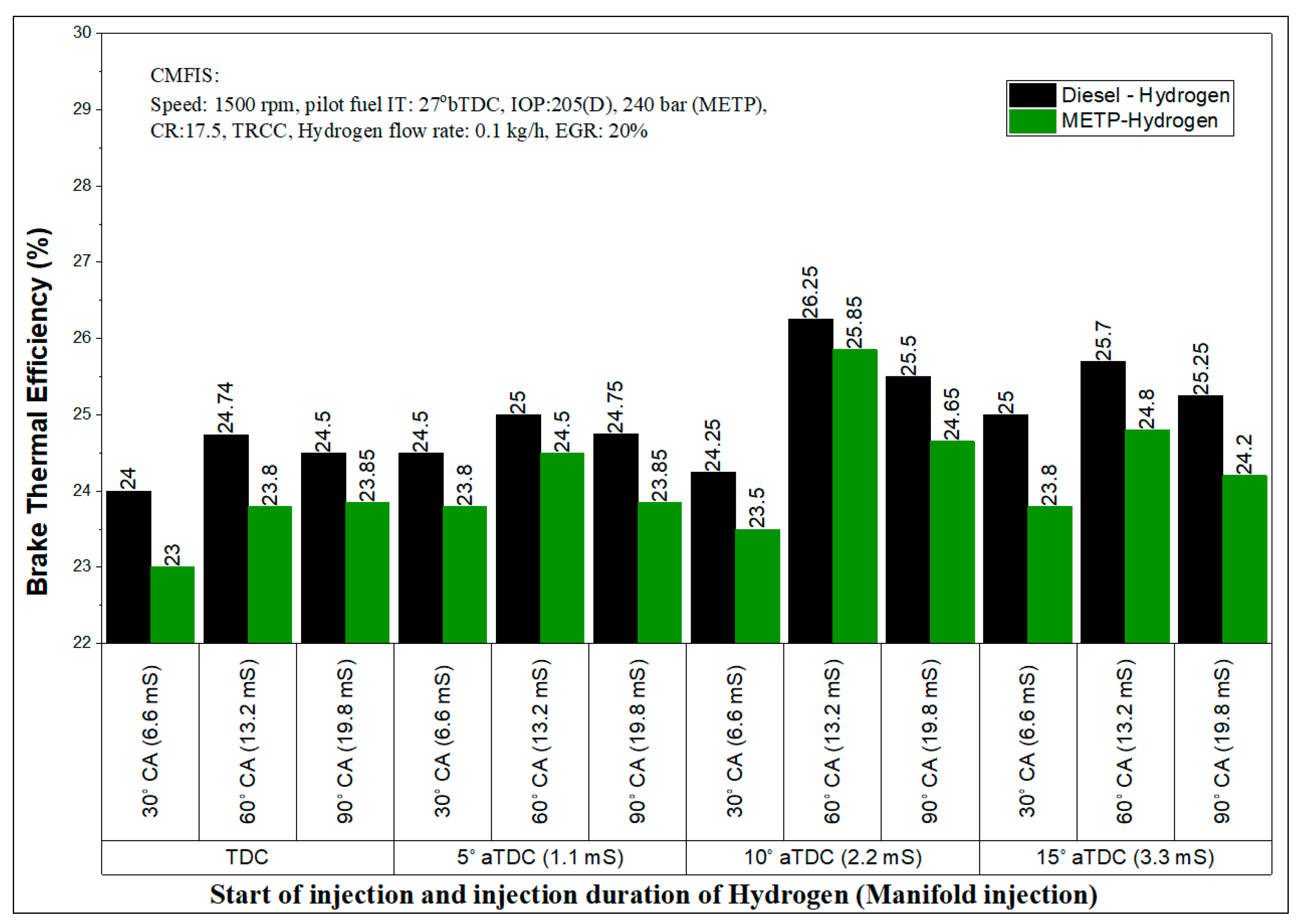
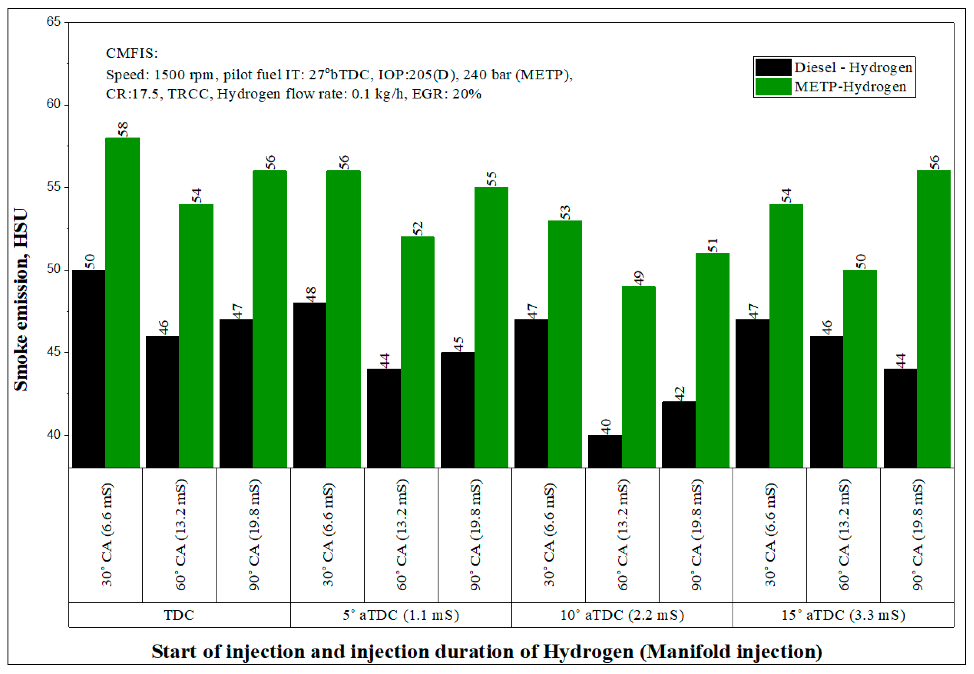
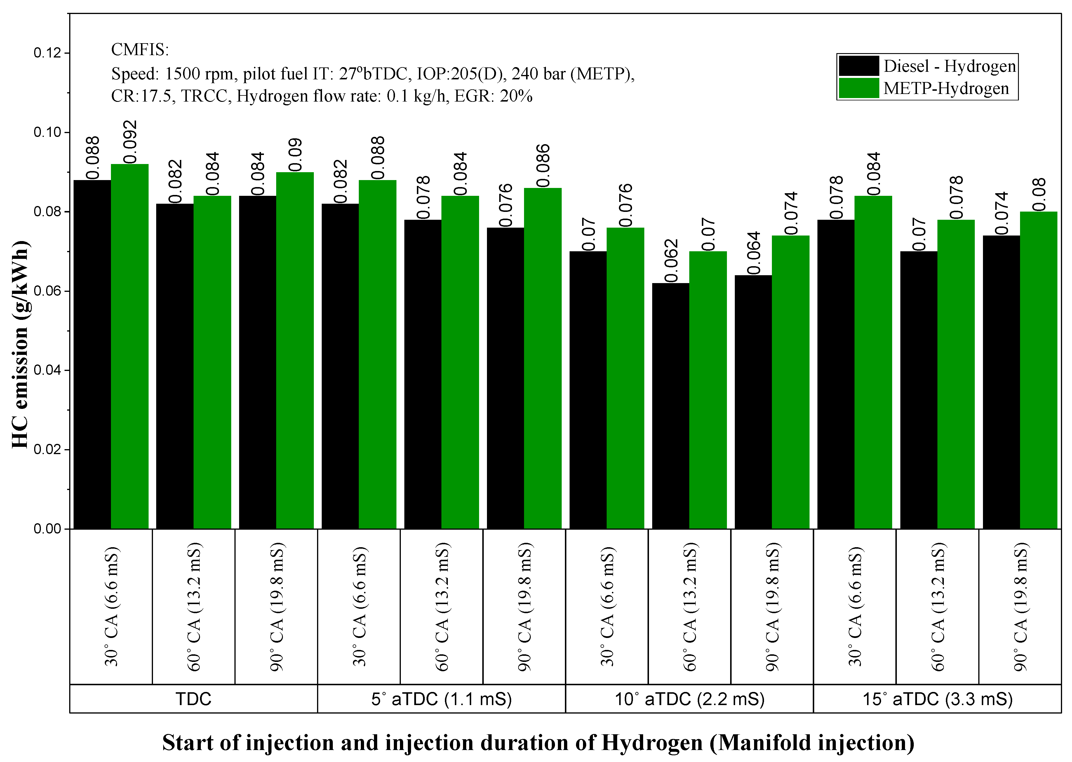
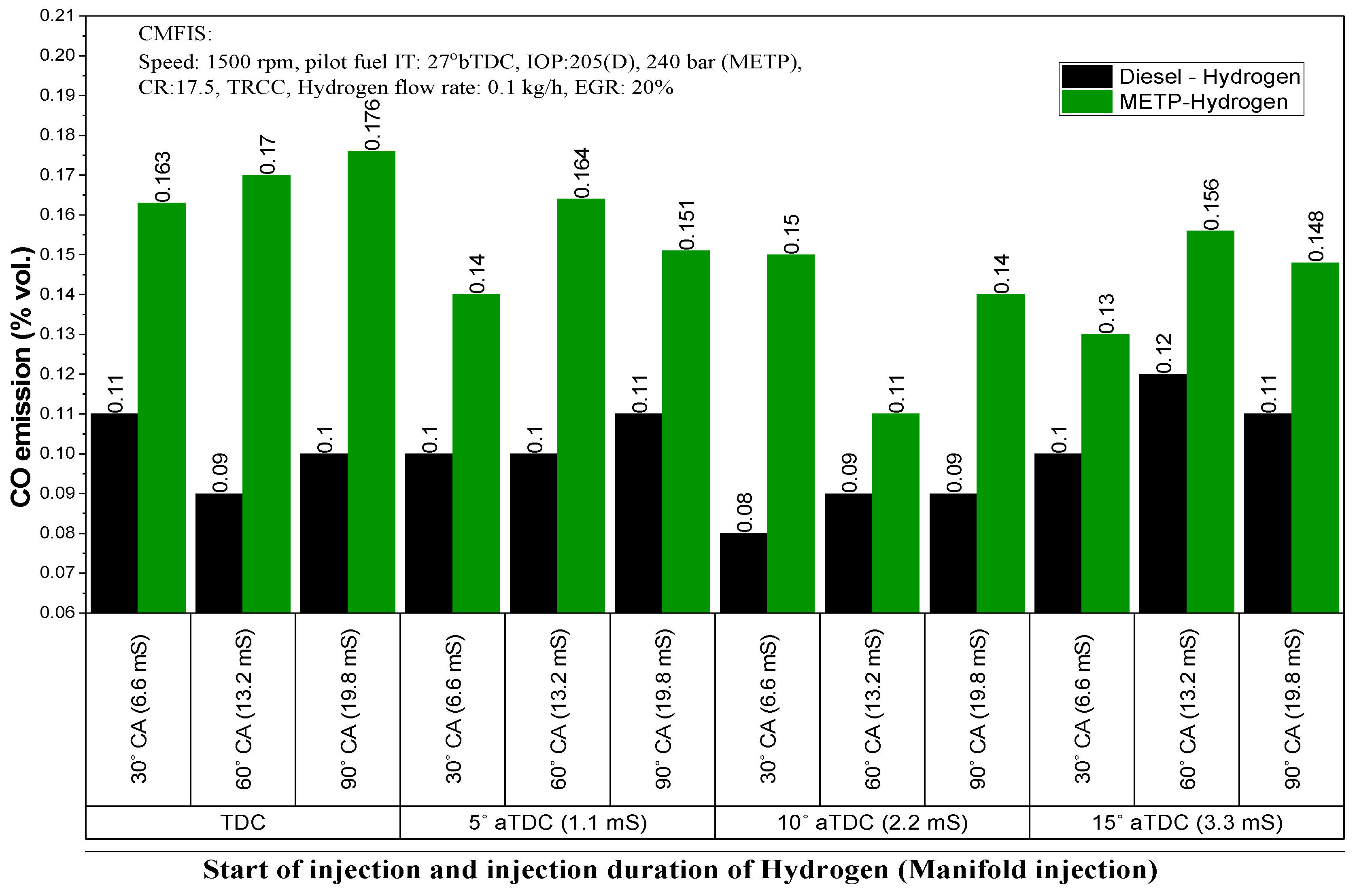
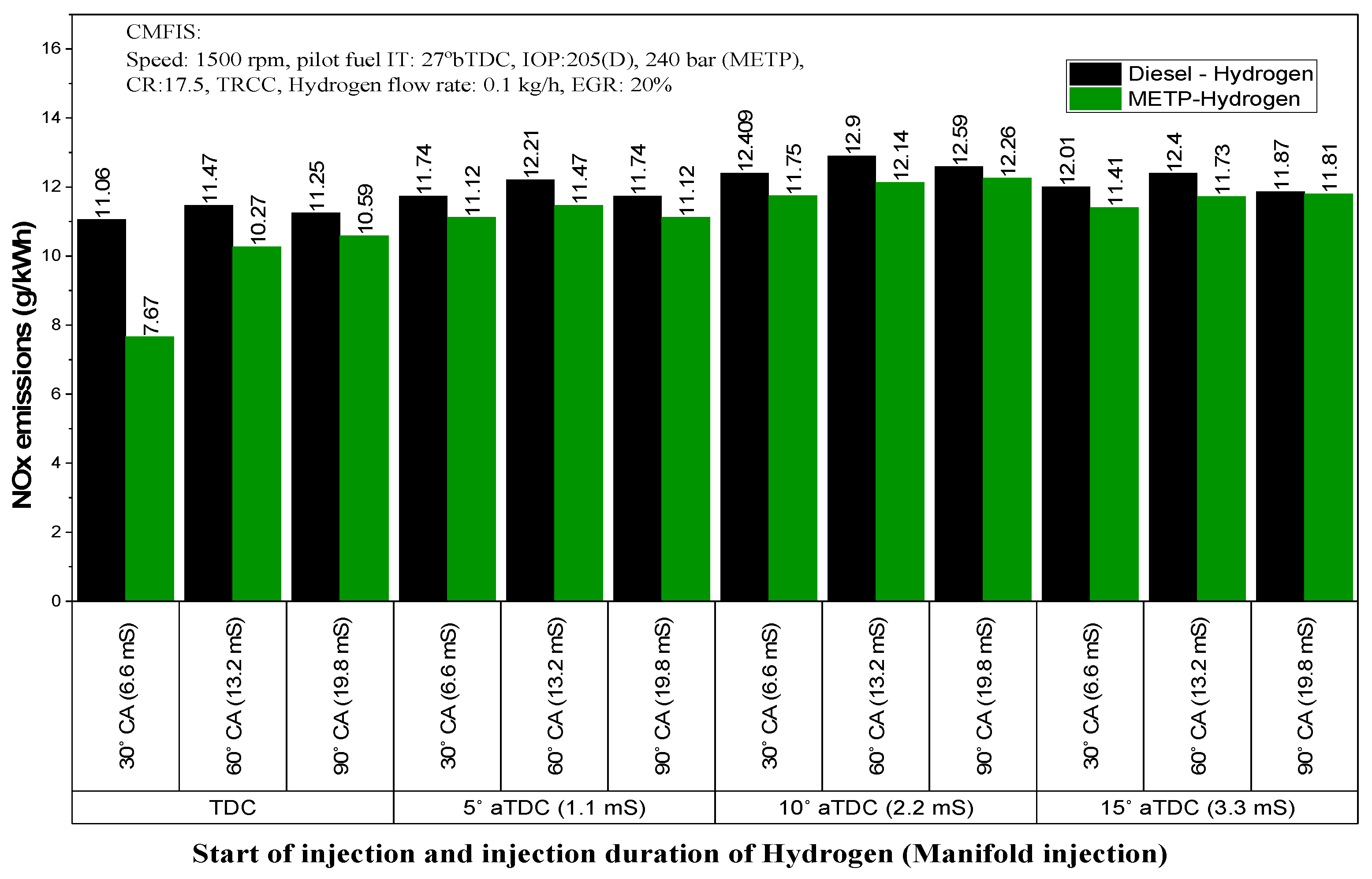
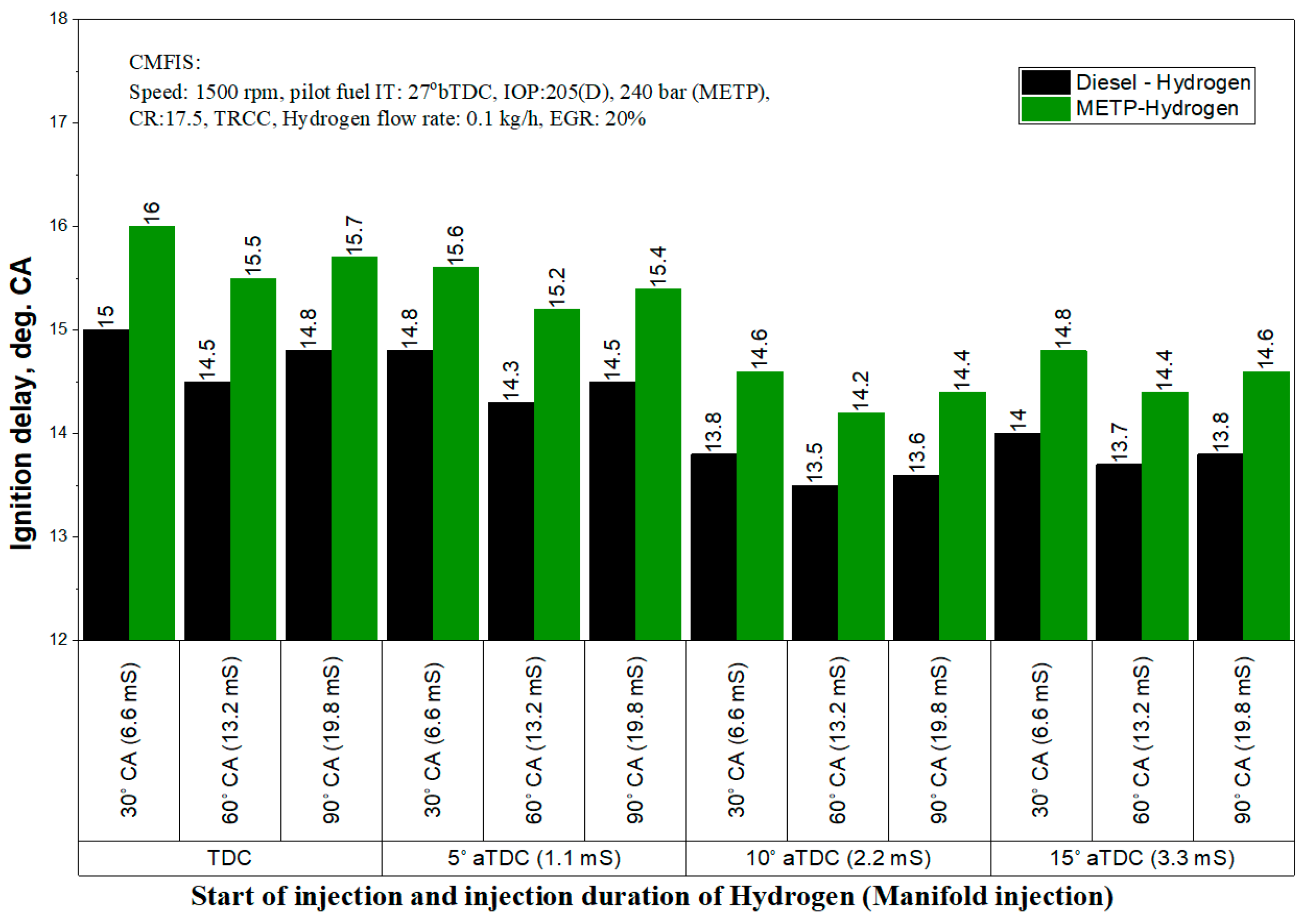
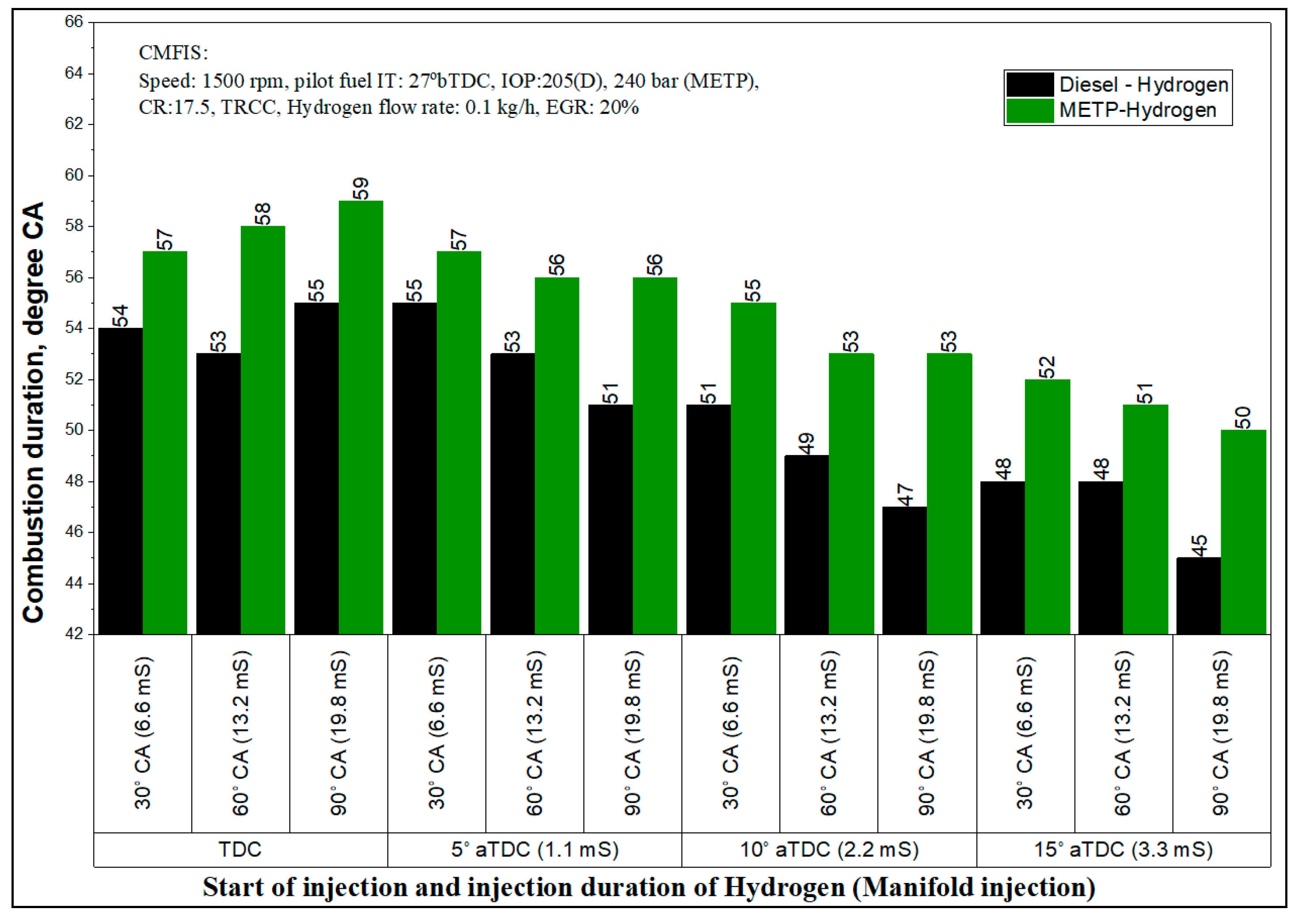
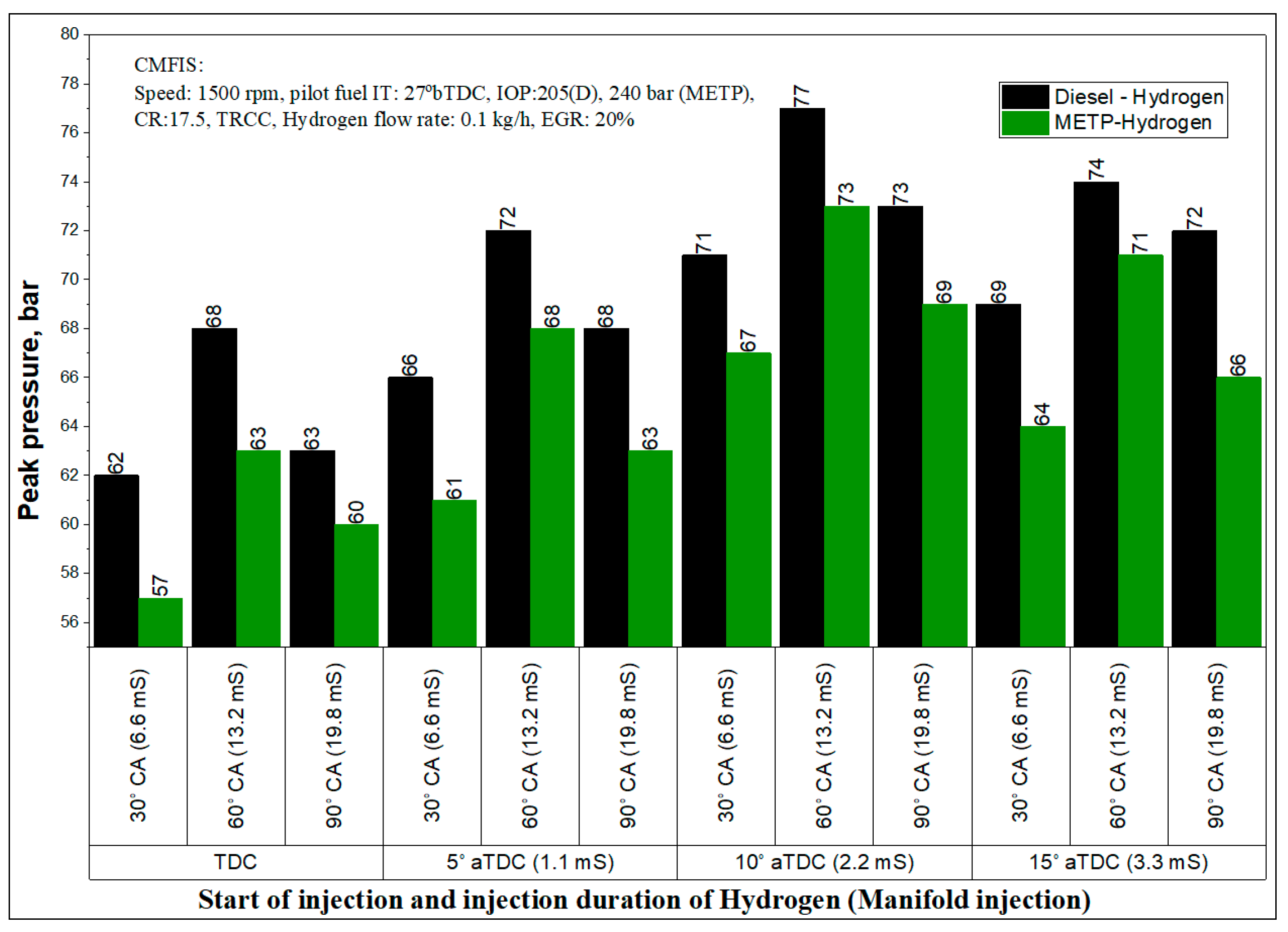
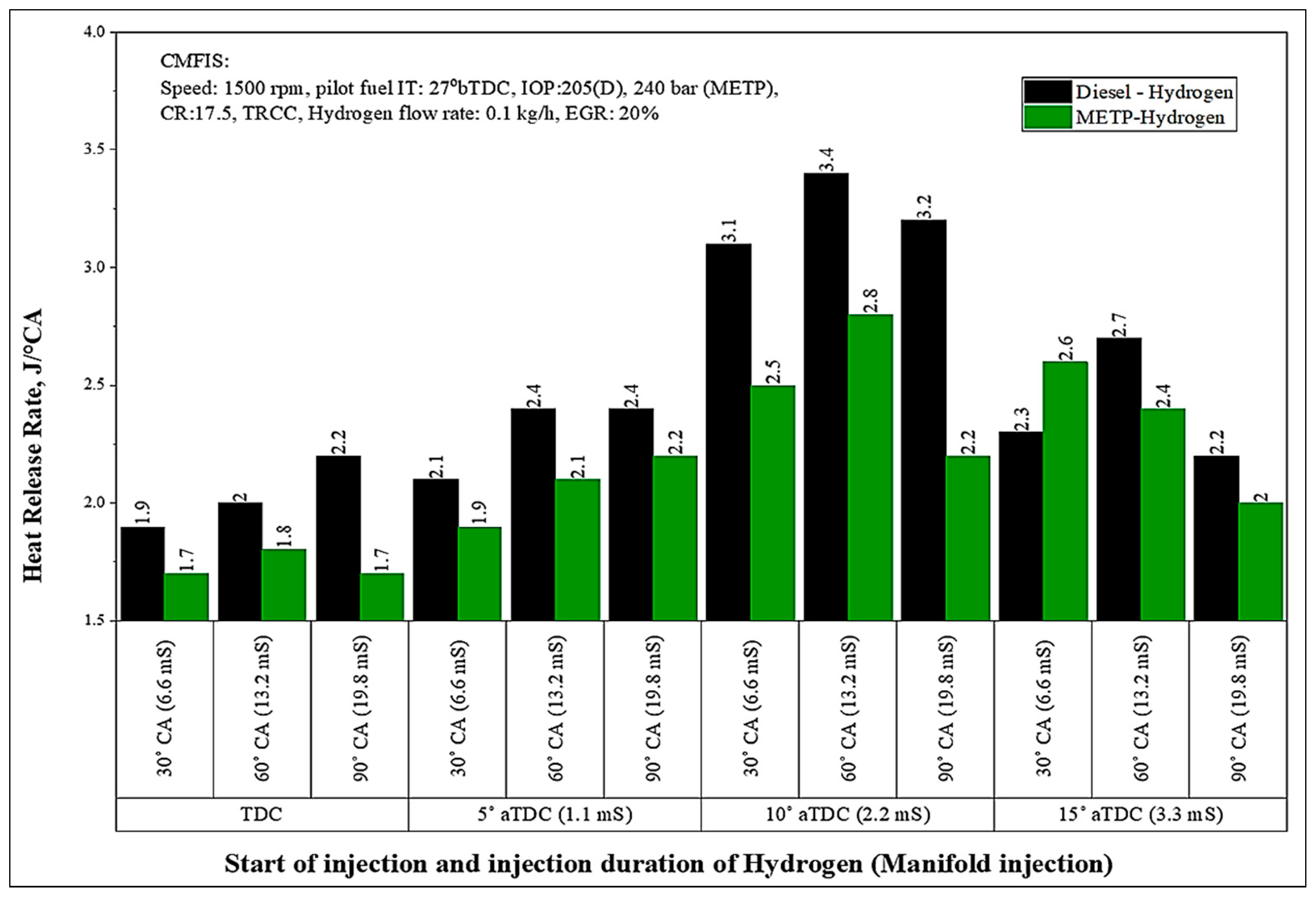
3.2. Impact of Hydrogen Start of Injection and its Injection Interval with a Fixed 20% EGR on the Performance of METP-Hydrogen Fueled Dual-Fuel Engine with Hydrogen Using the Manifold Injection Method

In this section, the impact of hydrogen starts of injection, and its injection duration was optimized for dual fuel engine procedure employing diesel/METP as injected fuels. Experimental investigations have been carried out to achieve comparative measures in conditions of performance and emissions. The effect of hydrogen injection timing and injection duration on brake thermal efficiency (BTE) of dual-fuel engine powered with diesel/METP-hydrogen using CMFIS facilities is presented in Figure 10 for 80% load, respectively. Further, hydrogen was injected (manifold) at varied injection timings and injection duration for 80% load. BTE for METP-hydrogen operation is observed to be smaller contrasted to diesel–hydrogen operation. Hydrogen properties being common, injected pilot fuel assets compete for a significant responsibility on the observed varied trends. Lower Cv and higher viscosity of METP caused lowered the engine performance when compared to diesel–hydrogen operation. With the manifold injection, enhanced combustion occurs due to improved air-hydrogen mixing that takes place before the mixture enters the engine cylinder. Further, the electronic injection of hydrogen in the manifold offers the greatest benefit towards precise control of the amount of Hydrogen entering into the intake of the engine. However, manifold injection of hydrogen leads to better mixing of hydrogen with air caused by the more time available for hydrogen to mix with air leading to better combustion. However, gas injector plays a major role in injection and is responsible for improved engine performance. Additionally, hydrogen has the highest flame velocity leading to increased burning of the complete fuel combination. Outcomes exhibited that METP-Hydrogen dual-fuel engine procedure with manifold injection was found to be smooth for selected injection timings when varied from TDC to 15° ATDC. As the SOI was varied from TDC to 10° ATDC, the performance was improved, and beyond 15° ATDC, a drop in BTE was observed for dual fuel engine operation. An increase in BTE might be ascribed to enhancement in the hydrogen mixing rate with air, and subsequently, improved combustion is followed by significant combustion rates associated with higher flame velocities of hydrogen and could be responsible for the presented results. At 15° ATDC, the maximum flame speed achievable during stoichiometric combustion may be reduced as at 10° ATDC, an appreciable amount of METP air mixture is already prepared during the delay period and combusts the mixture rapidly, giving higher rates of in-cylinder pressures in the engine cylinder [42]. At 15° ATDC, decreased BTE could be due to some of the hydrogen injected not burning in the engine cylinder and persisting into the exhaust and leaving the engine unburnt due to its higher auto-ignition temperature. For any given SOI for hydrogen injection duration of 60 °CA caused higher BTE and could be anticipated to additional period available for the uniform combination of hydrogen with air. This further leads to better burning taking place inside the engine cylinder. Finally, it is concluded that the burning was noticed to be smoother with injection timing of 10° ATDC and injection duration of 60 °CA, and these were optimized for hydrogen manifold injection for the dual-fuel engine.
This section is highlighted the various emission levels of the dual-fuel engine provided with CMFIS facilities and operated on METP-hydrogen with ECU controlled manifold injection of hydrogen. The variation of smoke emissions for various hydrogen injection timing and injection interval with CMIS for diesel/RuOMR-hydrogen-powered dual-fuel engine at 80% load is presented in Figure 11. Further, hydrogen was injected (manifold) at varied injection timings and injection duration for 80% load. For similar working situations, higher smoke concentrations were remarked for METP-Hydrogen in comparison to conventional oil-hydrogen operation. This might be ascribed to differences in injected pilot fuel properties such as higher viscosity and lower volatility of the METP [55]. As the SOI was varied from TDC to 10° ATDC smoke opacity decreased. The higher BTE at these SOIs could be responsible for the results obtained. Hydrogen injection at 10° ATDC with CMFIS facility results in higher peak pressure and burning temperatures prevailing inside the combustion chamber at the injection moment. Beyond 15° ATDC, smoke opacity is increased, probably due to incomplete combustion arising from improper air-hydrogen mixing. For all SOIs injection duration of 60 °CA showed lowered smoke opacity. Decreasing or increasing the injection duration concerning 60 °CA has not much effect on the smoke opacity reduction. Injection duration with 60 °CA resulted in a sufficient time availability for uniform mixing of both hydrogen and air [22,23]. It is concluded that Hydrogen SOI 10° ATDC and injection duration of 60 °CA led to uniform mixing of hydrogen with air. This could lead to better oxidation of the fuel mixture, leading to better cracking of the fuel combinations used [42]. In addition, Hydrogen has no carbon, and hence this factor might also be accountable for the remarked manner.
Figure 12 shows the emissions of HC of a dual-fuel engine fueled with diesel/METP-hydrogen operation in which diesel and METP were injected using both CMFIS. Further, Hydrogen was injected (manifold) at varied injection timings and injection duration for 80% load. Findings demonstrated that hydrogen injection with diesel resulted in lower HC intensity associated with METP-Hydrogen operation. This might be assigned to the poor burning characteristics of METP compared to diesel. Different injection timings and injection durations with CMFIS facility resulted in different HC levels. As the SOI of hydrogen was varied from TDC to 10° ATDC, HC emission was decreased. The higher BTE and reduced wall wetting at these SOIs could be responsible for the results obtained. Beyond 15° ATDC, HC emission is increased, probably due to incomplete combustion arising from improper air-hydrogen mixing. For all SOIs, the injection duration of 60 °CA showed lower HC. Decreasing or increasing the injection duration concerning 60 °CA has not much effect on the HC reduction [51]. For all SOIs, the injection duration of 60 °CA showed lower HC. Further, at 60 °CA injection duration, the hydrogen gets sufficient time to mix with air leading to a more homogeneous mixture. This can lead to better combustion of the fuel combinations used [26,32,45]. Therefore, it is concluded that for 10° ATDC hydrogen injection and 60 °CA duration with CMFIS was found to be optimum. Advancing or retarding the hydrogen injection regarding 10° ATDC caused a higher HC level, and this might be attributed to non-uniform air-hydrogen mixtures with reduced chemical kinetics observed during the ignition delay period.
Figure 13 indicates the emissions of CO of a dual-fuel engine fueled with diesel/METP- hydrogen operation in which diesel and METP were injected using both CMFIS. Further, hydrogen was injected (manifold) at varied injection timings and injection duration for 80% load. Biodiesel operation with hydrogen injection has higher CO emission levels over a given range of operating conditions contrasted to petroleum oil-hydrogen operation. It might be ascribed to their higher viscosity and lower volatility [51]. This is primarily attributed to the decrease burning rates associated with biodiesel triggered by heightened area of quenching interior combustion chamber with Hydrogen injection. The lower BTE obtained with HB-hydrogen might be accountable for the risen CO level contrasted to petroleum oil-hydrogen injection. It is observed that hydrogen manifold injection produces lesser CO emission levels. As the SOI was varied from TDC to 10° ATDC, emissions of CO decreased. The higher BTE at these SOIs might be accountable for the results obtained. Beyond 15° ATDC CO increased probably due to incomplete combustion arising from improper air-hydrogen mixing. For all SOIs, the injection duration of 60 °CA showed lower CO. Decreasing or increasing the injection duration with respect to 60 °CA has not much effect on the smoke opacity reduction. Further, at 60 °CA injection duration, the hydrogen gets sufficient time to mix with air leading to a more homogeneous mixture. This further assists in the augmented burning of the fuel combinations used caused by their better oxidation [38]. Hence, CO levels were decreased for the combination of 10° ATDC injection timing and 60 °CA injection duration. Dual fuel procedure with a manifold injection when the engine was conducted with hydrogen injection timing of 10° BTDC and injection interval of 60 °CA triggers into lower CO quantities. Reduction in oxidation rate instigated by the substitute of air by hydrogen and dropped burning temperature may be accountable for the noticed tendencies. Further it is observed that at all SOI with port injection of hydrogen and injection durations lead to reduced air intake and air-hydrogen mixing. Pilot fuel injection of METP with CMFIS system in dual fuel engine may decrease the atomization leading to increased CO amounts.
Figure 14 illustrates the emissions of NOx emissions of a dual-fuel engine fuelled with diesel/METP-hydrogen operation in which diesel and METP were injected using both CMFIS. Further, hydrogen was injected (manifold) at varied injection timings and injection duration for 80% load. NOX concentrations grow when the burning occurs in the presence of oxygen and at higher peak combustion temperatures and boosted residence time. For all the operating parameters used, higher NOX concentrations were detected for diesel–hydrogen dual fuel operation compared to METP-hydrogen, a dual-fuel operation. Higher premixed combustion phase associated with diesel compared to METP with hydrogen injection (manifold) being common is mainly responsible for these trends of results. Higher temperature prevailing inside the combustion chamber instigated by the utilization of hydrogen leads to higher NOX for both liquid pilot fuels injected [32,38,45]. Investigations on dual fuel operation with CMIS facilities using a manifold injection of hydrogen at injection timing of 10° ATDC and injection duration of 60 °CA causes into higher NOx concentrations. As the SOI has differed from TDC to 10° ATDC, NOx enlarged. Improved engine performance with higher BTE at these SOIs could be accountable for the findings achieved. Beyond 15° ATDC, emissions of NOx reduced, possibly attributed to incomplete burning arising from improper air-hydrogen mixing with decreased in-cylinder temperatures. For all SOIs, the injection duration of 60 °CA showed higher NOx, and this could be due to a higher premixed combustion phase as more fuel burns during this phase. Decreasing or increasing the injection duration concerning 60 °CA has not much effect on the NOx increase. Hence higher NOx levels were exhausted when the combustion is taking place at increased combustion temperatures in the flame zone. Injection of hydrogen increases the combustion temperature attributed to its higher burning speed facilitating enhanced flame propagation during the burning process [47]. Further, at 60 °CA injection duration, the hydrogen gets sufficient time to mix with air, leading to a more homogeneous mixture. This can cause better burning of the fuel combinations utilized by enhanced oxidation of the fuel combinations. Hence, it is concluded that the NOx concentrations were enhanced at 10° ATDC injection timing and 60 °CA injection duration.
This section highlights the various burning factors such as ID, CD, peak pressure, HRR associated with METP-hydrogen operated dual-fuel engine with ECU controlled hydrogen using both manifold and port injection methods. Injection of hydrogen plays a significant role in the combustion behavior as compared to when the same was inducted [47]. Figure 15 shows the ignition delay of a modified dual-fuel engine fueled with diesel/METP-hydrogen operation in which diesel and METP were injected using both CMFIS. Further, hydrogen was injected (manifold) at varied injection timings and injection duration for 80 and 100% load. Hydrogen injection is common, and for the same SOI and injection duration for the dual-fuel engine operation durations, higher viscosity and lower cetane number of the METP resulted in increased ignition delay compared to diesel. At an optimized SOI of 10° ATDC and 60 °CA, the injection duration was found for all the cases considered. Results showed that beyond 10° ATDC injection timing and for varied injection duration, lowered peak pressures with heightened ignition delay has been observed. Further, at other operating conditions, the mixing of air-hydrogen becomes challenging and requires higher chemical delay.
Figure 16 demonstrates the combustion duration of a modified dual-fuel engine fueled with diesel/METP-hydrogen operation in which diesel and METP were injected using both CMFIS facilities. Further, Hydrogen was injected (manifold) at varied injection timings and injection duration for 80% and 100% load. For all the operating conditions tested, higher combustion durations were obtained for METP-hydrogen engine operation when in comparison to diesel–hydrogen operation. It might be anticipated to the lower peak pressures observed during the premixed combustion phase associated with reduced HRR [20,31]. Higher viscosity and lower calorific value of the METP, along with incomplete mixing of fuel combination is also responsible for increased combustion duration [32]. At optimized SOI of 10° ATDC and 60 °CA injection duration with CMFIS facility, combustion duration decreased compared to other tested parameters used. This is due to improved air-hydrogen mixing caused by the enhanced chemical kinetics leading to an increase in the combustion temperature. However, for manifold controlled injection of Hydrogen with CMFIS operation, lowered combustion durations occurred, and this could be due to improved air-fuel mixing obtained in the former method. However, beyond 10° ATDC injection timing and for varied injection duration, lowered peak pressures with increasing combustion duration has been observed. Reduced premixed combustion lead to higher combustion duration [32]. Further, at other operating conditions, the mixing of air-hydrogen becomes difficult and requires higher chemical delay. It is concluded that SOI of 10° ATDC and duration of 60 °CA and with CMFIS and manifold gas injection facility resulted in a reduction in the combustion durations compared to other SOI and injection durations tested.
Figure 17 indicates the peak pressure variation for modified dual-fuel engine fuelled with diesel/METP-hydrogen operation in which diesel and METP were injected using both CMFIS facilities. Additionally, hydrogen was injected (manifold) at varied injection timings and injection duration for 80% load. METP showed lower peak pressures due to lowered BTE associated with lowered premixed HRR with both gas and liquid injection facilities. Peak pressures were higher for pilot fuel injection of METP with CRDI system as higher fuel injection pressure may enhance the fuel mixing rates due to optimized fuel droplet sizes. At injection timing of 10° ATDC and injection duration of 60 °CA for hydrogen in both versions of the manifold and port injection, higher peak pressures were found for both diesel–hydrogen and METP-hydrogen dual-fuel operation compared to other test conditions. At these conditions, the flame speed of hydrogen burning in the air being higher, the energy required to initiate the combustion with hydrogen is less. A combination of hydrogen and air are combustible over an exceptionally varied assortment of flammability restrictions at ordinary temperatures and can continue from 4% to 74% by volume of hydrogen in air.
The ignition delay is the time lag between the start of injection and the start of ignition. The start of injection was obtained based on the static injection timing. ID is measured from cylinder pressure versus crank angle diagrams. It is measured from the start of injection to the start of combustion (where the pressure curve deviates). Combustion duration was measured from the start of combustion to 90% of the cumulative heat release rate. In cylinder-pressure was measured with a piezoelectric transducer. Peak pressure refers to the maximum cylinder pressure observed in the cycle.
Figure 18 present the variation of injection timing and injection duration on the HRR of the modified dual-fuel engine fueled with diesel/METP-hydrogen combination in which diesel and METP were injected using both CMFIS facilities at 80% load. Moreover, hydrogen was injected (manifold) at varied injection timings and injection duration for 80 and 100% load. METP showed lower HRRs due to lowered BTE associated with reduced premixed combustion phase with both gas and liquid injection facilities. HRRs were higher for pilot fuel injection of METP with CDRI system as higher fuel injection pressure may enhance the fuel mixing rates due to optimized fuel droplet sizes [56]. Lower HRR for METP-hydrogen obtained could be due to the fact that the hydrogen injection during the intake process lowers the in-cylinder temperatures. This could result in retarded primary fuel combustion. In addition, the lower calorific value of METP in both versions of CMFIS injection facilities relative to diesel fuel is associated with reduced premixed combustion with hydrogen fuel injection may be accountable for the diminished HRR when contrasted to diesel function. At an injection timing of 10° ATDC and injection duration of 60 °CA for hydrogen in both CMFIS of manifold injection, higher HRRs were found for both diesel–hydrogen and METP-hydrogen dual-fuel operation compared to other tested conditions. At these conditions, the flame speed of Hydrogen burning in the air is increased, while the energy required to initiate the burning with hydrogen is reduced. However, at other SOIs and injection durations, the combustion of hydrogen led to reduced pressure and temperature instigated by the diminished blending rates of air-hydrogen mixtures. Hence with CMFIS facility, at SOI of 10° ATDC and injection duration of 60 °CA, higher HRR has been noticed.

4. Conclusions

In the current study, the engine operated smoothly at a fixed speed of 1500 rpm with very minimal vibration and noise level. Subsequent conclusions were derived from investigations undertaken:
  • Optimized SOI of 10° ATDC and 60 °CA duration provides an enhancement in dual-fuel engine performance with METP and hydrogen fuel mixtures in manifold injection method with CMFIS system.
  • Precise injection of gaseous fuels in the manifold injection along with CMFIS amenities can additionally provide further improvement in power characteristics and emission stability.
  • Manifold injection provides uniform mixing of air-hydrogen and thereby augments the dual-fuel engine performance in conditions of augmented BTE, diminished smoke, HC and CO emissions. However the study noticed boost in the magnitude of NOx emissions.
  • The CMFIS method integrated with manifold injection of gaseous fuel can lead to considerable improvement in engine performance.
The reported study can be further extended to incorporate investigations on regulation of hydrogen flowrate, alternate fuel blends and varying load conditions. Also, there is further scope on the study of effect of nanoparticle fuel additives ternary fuel blends [57,58,59,60,61,62].

Author Contributions

M.M. (Mahantesh Marikatti), conceptualization, methodology, investigation; N.R.B., V.S.Y. and Y.B., supervision, project administration, draft and resources; M.E.M.S., interpretation of results, conceptualization and reviewing; F.P.G.M., formal analyses, reviewing; M.M. (MA Mujtaba), formal analyses, review and editing; H.F. and B.N., review and editing, validation; T.Y.K., writing methodology; A.A. and A.I.E.-S., review and editing. All authors have read and agreed to the published version of the manuscript.

Funding

This research received no external funding.

Conflicts of Interest

The authors declare no conflict of interest.

Nomenclature

ASTMAmerican Society of Testing and Materials
ATDCAfter top dead center
SFCSpecific Fuel Consumption
BSFCBrake Specific Fuel Consumption
BSECBrake Specific Energy Consumption
CCCombustion chamber
°CACrank angle (degrees)
COCarbon monoxide
UHCUnburned Hydrocarbons
CPCylinder pressure
CNGCompressed Natural Gas
LPGLiquefied Petroleum Gas
CRDICommon Rail Direct Injection
CFDComputational Fluid Dynamics
ECUElectronic control unit
H2Hydrogen
HRRHeat release rate
IPInjection pressure
METPMethyl Ester Thevetia peruviana
PPPeak Pressure
TCCToroidal CC
BTEBrake Thermal Efficiency
BPBrake Power
TDCTop dead center
BTDCBefore top dead center
CDCombustion duration
CICompression ignition
CO2Carbon dioxide
CRCompression ratio
CMFISConventional Mechanical Fuel Injection System
BMEPBrake Mean Effective Pressure
IMEPIndicated Mean Effective Pressure
EGRExhaust gas recirculation
HCCHemispherical CC
HCNGhydrogenated compressed natural gas
IDIgnition delay
ITInjection timing
NOXOxides of nitrogen
TRCCToroidal re-entrant CC
UBHCUnburnt hydrocarbon

References

  1. Soudagar, M.E.M.; Nik-Ghazali, N.-N.; Kalam, M.; Badruddin, I.A.; Banapurmath, N.; Ali, M.A.B.; Kamangar, S.; Cho, H.M.; Akram, N. An investigation on the influence of aluminium oxide nano-additive and honge oil methyl ester on engine performance, combustion and emission characteristics. Renew. Energy 2020, 146, 2291–2307. [Google Scholar] [CrossRef]
  2. Delvi, M.K.; Soudagar, M.E.M.; Khan, H.; Ahmed, Z.; Shariff, I.M. Biodiesel production utilizing diverse sources, classification of oils and their esters, performance and emission characteristics: A research. Int. J. Recent Technol. Eng. 2019, 8, 1–8. [Google Scholar]
  3. Mujtaba, M.; Masjuki, H.; Kalam, M.; Noor, F.; Farooq, M.; Ong, H.C.; Gul, M.; Soudagar, M.E.M.; Bashir, S.; Rizwanul Fattah, I. Effect of additivized biodiesel blends on diesel engine performance, emission, tribological characteristics, and lubricant tribology. Energies 2020, 13, 3375. [Google Scholar] [CrossRef]
  4. El-Seesy, A.I.; Hassan, H.; Ibraheem, L.; He, Z.; Soudagar, M.E.M. Combustion, emission, and phase stability features of a diesel engine fueled by jatropha/ethanol blends and n-butanol as co-solvent. Int. J. Green Energy 2020, 17, 1–12. [Google Scholar] [CrossRef]
  5. Soudagar, M.E.M.; Nik-Ghazali, N.-N.; Badruddin, I.A.; Kalam, M.; Kittur, M.I.; Akram, N.; Ullah, M.A.; Khan, T.Y.; Mokashi, I. Production of Honge Oil Methyl Ester (Home) and Its Performance Test on Four Stroke Single Cylinder vcr Engine. In AIP Conference Proceedings; AIP Publishing LLC: Melville, NY, USA, 2019; p. 200006. [Google Scholar]
  6. Gavhane, S.R.; Kate, M.A.; Pawar, A.; Safaei, M.R.; M Soudagar, M.E.; Mujtaba Abbas, M.; Muhammad Ali, H.; Banapurmath, R.N.; Goodarzi, M.; Badruddin, I.A. Effect of zinc oxide nano-additives and soybean biodiesel at varying loads and compression ratios on vcr diesel engine characteristics. Symmetry 2020, 12, 1042. [Google Scholar] [CrossRef]
  7. Márquez, F.P.G.; Karyotakis, A.; Papaelias, M. Renewable Energies: Business Outlook 2050; Springer: Berlin/Heidelberg, Germany, 2018. [Google Scholar]
  8. Soudagar, M.E.M.; Nik-Ghazali, N.-N.; Kalam, M.A.; Badruddin, I.; Banapurmath, N.; Akram, N. The effect of nano-additives in diesel-biodiesel fuel blends: A comprehensive review on stability, engine performance and emission characteristics. Energy Convers. Manag. 2018, 178, 146–177. [Google Scholar] [CrossRef]
  9. Pliego Marugán, A.; Garcia Marquez, F.P.; Lev, B. Optimal decision-making via binary decision diagrams for investments under a risky environment. Int. J. Prod. Res. 2017, 55, 5271–5286. [Google Scholar] [CrossRef]
  10. Marugan, A.P.; Márquez, F.P.G. Decision-Making Management: A Tutorial and Applications; Academic Press: Cambridge, MA, USA, 2017. [Google Scholar]
  11. Khan, H.; Soudagar, M.E.M.; Kumar, R.H.; Safaei, M.R.; Farooq, M.; Khidmatgar, A.; Banapurmath, N.R.; Farade, R.A.; Abbas, M.M.; Afzal, A. Effect of nano-graphene oxide and n-butanol fuel additives blended with diesel—Nigella sativa biodiesel fuel emulsion on diesel engine characteristics. Symmetry 2020, 12, 961. [Google Scholar] [CrossRef]
  12. Soudagar, M.E.M.; Nik-Ghazali, N.-N.; Akram, N.; Al-Rashid, M.A.; Badruddin, I.A.; Khan, H.; Kallannavar, V.; Shahpurkar, K.; Afzal, A.; Farade, R. The Potential of Nanoparticle Additives in Biodiesel: A Fundamental Outset. In AIP Conference Proceedings, 2020; AIP Publishing LLC: Melville, NY, USA, 2020; p. 030003. [Google Scholar]
  13. Soudagar, M.E.M.; Kittur, P.; Parmar, F.; Batakatti, S.; Kulkarni, P.; Kallannavar, V. Production of Mahua Oil Ethyl Ester (Moee) and Its Performance Test on Four Stroke Single Cylinder vcr Engine. In IOP Conference Series: Materials Science and Engineering, 2017; IOP Publishing: Bristol, UK, 2017. [Google Scholar]
  14. Muñoz, C.Q.G.; Márquez, F.P.G. Future maintenance management in renewable energies. In Renewable Energies; Springer: Berlin/Heidelberg, Germany, 2018; pp. 149–159. [Google Scholar]
  15. Sadeghian, O.; Moradzadeh, A.; Mohammadi-Ivatloo, B.; Abapour, M.; Garcia Marquez, F.P. Generation units maintenance in combined heat and power integrated systems using the mixed integer quadratic programming approach. Energies 2020, 13, 2840. [Google Scholar] [CrossRef]
  16. Dey, B.; García Márquez, F.P.; Basak, S.K. Smart energy management of residential microgrid system by a novel hybrid mgwoscacsa algorithm. Energies 2020, 13, 3500. [Google Scholar] [CrossRef]
  17. ETEnergyWorld. India can generate 18,000 megawatt renewable energy using biomass. The Economic Times, 9 December 2019.
  18. Yaliwal, V.; Banapurmath, N.; Gireesh, N.; Tewari, P. Production and utilization of renewable and sustainable gaseous fuel for power generation applications: A review of literature. Renew. Sustain. Energy Rev. 2014, 34, 608–627. [Google Scholar] [CrossRef]
  19. Yaliwal, V.; Banapurmath, N.; Tewari, P. Performance, combustion and emission characteristics of a single-cylinder, four-stroke, direct injection diesel engine operated on a dual-fuel mode using honge oil methyl ester and producer gas derived from biomass feedstock of different origin. Int. J. Sustain. Eng. 2014, 7, 253–268. [Google Scholar] [CrossRef]
  20. Banapurmath, N.; Gireesh, N.; Basavarajappa, Y.; Hosmath, R.; Yaliwal, V.; Pai, A.; Gopal Navale, K.; Jog, P.; Tewari, P. Effect of hydrogen addition to cng in a biodiesel-operated dual-fuel engine. Int. J. Sustain. Eng. 2015, 8, 332–340. [Google Scholar] [CrossRef]
  21. Ministry of New and Renewable Energy. Bio Energy; Ministry of New and Renewable Energy: New Delhi, India, 2019. Available online: https://mnre.gov.in/ (accessed on 1 October 2020).
  22. Das, L. Hydrogen engines: A view of the past and a look into the future. Int. J. Hydrogen Energy 1990, 15, 425–443. [Google Scholar] [CrossRef]
  23. Das, L. Hydrogen engine: Research and development (r&d) programmes in indian institute of technology (iit), delhi. Int. J. Hydrogen Energy 2002, 27, 953–965. [Google Scholar]
  24. Raman, V.; Hansel, J.; Fulton, J.; Lynch, F. Hythane-an ultraclean transportation fuel. Hydrog. Energy Prog. 1994, 3, 1797. [Google Scholar]
  25. Akansu, S.O.; Bayrak, M. Experimental study on a spark ignition engine fueled by ch4/h2 (70/30) and lpg. Int. J. Hydrogrn Energy 2011, 36, 9260–9266. [Google Scholar] [CrossRef]
  26. Pullagura, G.; BabjiAlapati, M.; Prakash, R. Effect of hydrogen enrichment on the combustion characteristics of a biofuel diesel engine. IosrjenIssn 2012, 2, 2250–3021. [Google Scholar] [CrossRef]
  27. Gosal, M.; Das, L.; Babu, M.G. Improved efficiency of cng using hydrogen in spark ignition engine. J. Pet. Technol. Altern. Fuels 2013, 4, 99–112. [Google Scholar]
  28. Liu, J.; Yang, F.; Wang, H.; Ouyang, M.; Hao, S. Effects of pilot fuel quantity on the emissions characteristics of a cng/diesel dual fuel engine with optimized pilot injection timing. Appl. Energy 2013, 110, 201–206. [Google Scholar] [CrossRef]
  29. Mahla, S.; Das, L.; Babu, M. Effect of egr on performance and emission characteristics of natural gas fueled diesel engine. Jordan J. Mech. Ind. Eng. 2010, 4, 523–530. [Google Scholar]
  30. Furuhama, S.; Yamane, K.; Yamaguchi, I. Combustion improvement in a hydrogen fueled engine. Int. J. Hydrogen Energy 1977, 2, 329–340. [Google Scholar] [CrossRef]
  31. Naber, J.; Siebers, D. Hydrogen combustion under diesel engine conditions. Int. J. Hydrogen Energy 1998, 23, 363–371. [Google Scholar] [CrossRef]
  32. Varde, K.; Frame, G. Hydrogen aspiration in a direct injection type diesel engine-its effects on smoke and other engine performance parameters. Int. J. Hydrogen Energy 1983, 8, 549–555. [Google Scholar] [CrossRef] [Green Version]
  33. Kitagawa, T.; Kido, H.; Nakamura, N.; Aishima, M. Flame inertia into lean region in stratified hydrogen mixture. Int. J. Hydrogen Energy 2005, 30, 1457–1464. [Google Scholar] [CrossRef]
  34. Soberanis, M.E.; Fernandez, A. A review on the technical adaptations for internal combustion engines to operate with gas/hydrogen mixtures. Int. J. Hydrogen Energy 2010, 35, 12134–12140. [Google Scholar] [CrossRef]
  35. Kumar, M.S.; Ramesh, A.; Nagalingam, B. Use of hydrogen to enhance the performance of a vegetable oil fuelled compression ignition engine. Int. J. Hydrogen Energy 2003, 28, 1143–1154. [Google Scholar]
  36. Geo, V.E.; Nagarajan, G.; Nagalingam, B. Studies on dual fuel operation of rubber seed oil and its bio-diesel with hydrogen as the inducted fuel. Int. J. Hydrogen Energy 2008, 33, 6357–6367. [Google Scholar]
  37. Saravanan, N.; Nagarajan, G. An experimental investigation on hydrogen fuel injection in intake port and manifold with different egr rates. Int. J. Energy Environ. 2010, 1, 221–248. [Google Scholar]
  38. Korakianitis, T.; Namasivayam, A.; Crookes, R. Hydrogen dual-fuelling of compression ignition engines with emulsified biodiesel as pilot fuel. Int. J. Hydrogen Energy 2010, 35, 13329–13344. [Google Scholar] [CrossRef]
  39. Dimitriou, P.; Kumar, M.; Tsujimura, T.; Suzuki, Y. Combustion and emission characteristics of a hydrogen-diesel dual-fuel engine. Int. J. Hydrogen Energy 2018, 43, 13605–13617. [Google Scholar] [CrossRef]
  40. Serrano, J.; Jiménez-Espadafor, F.; López, A. Analysis of the effect of different hydrogen/diesel ratios on the performance and emissions of a modified compression ignition engine under dual-fuel mode with water injection. Hydrogen-diesel dual-fuel mode. Energy 2019, 172, 702–711. [Google Scholar] [CrossRef]
  41. Khan, N.; Balunaik, B.; Yousufuddin, S. Performance and emission characteristics of a diesel engine with varying injection pressure and fueled with hydrogen and cottonseed oil methyl ester blends. Mater. Today Proc. 2018, 5, 3369–3377. [Google Scholar] [CrossRef]
  42. Koten, H. Hydrogen effects on the diesel engine performance and emissions. Int. J. Hydrogen Energy 2018, 43, 10511–10519. [Google Scholar] [CrossRef]
  43. Liew, C.; Li, H.; Nuszkowski, J.; Liu, S.; Gatts, T.; Atkinson, R.; Clark, N. An experimental investigation of the combustion process of a heavy-duty diesel engine enriched with H2. Int. J. Hydrogen Energy 2010, 35, 11357–11365. [Google Scholar] [CrossRef]
  44. Chintala, V.; Subramanian, K.A. Assessment of maximum available work of a hydrogen fueled compression ignition engine using exergy analysis. Energy 2014, 67, 162–175. [Google Scholar] [CrossRef]
  45. Rakopoulos, C.; Kyritsis, D. Hydrogen enrichment effects on the second law analysis of natural and landfill gas combustion in engine cylinders. Int. J. Hydrogen Energy 2006, 31, 1384–1393. [Google Scholar] [CrossRef]
  46. Sandalcı, T.; Karagöz, Y. Experimental investigation of the combustion characteristics, emissions and performance of hydrogen port fuel injection in a diesel engine. Int. J. Hydrogen Energy 2014, 39, 18480–18489. [Google Scholar] [CrossRef]
  47. Loganathan, M.; Velmurugan, A.; Page, T.; Gunasekaran, E.J.; Tamilarasan, P. Combustion analysis of a hydrogen-diesel fuel operated di diesel engine with exhaust gas recirculation. Front. Energy 2017, 11, 568–574. [Google Scholar] [CrossRef]
  48. Santoso, W.; Bakar, R.; Nur, A. Combustion characteristics of diesel-hydrogen dual fuel engine at low load. Energy Procedia 2013, 32, 3–10. [Google Scholar] [CrossRef] [Green Version]
  49. Masood, M.; Ishrat, M.; Reddy, A. Computational combustion and emission analysis of hydrogen–diesel blends with experimental verification. Int. J. Hydrogen Energy 2007, 32, 2539–2547. [Google Scholar] [CrossRef]
  50. Banapurmath, N.; Tewari, P.; Hosmath, R. Experimental investigations of a four-stroke single cylinder direct injection diesel engine operated on dual fuel mode with producer gas as inducted fuel and honge oil and its methyl ester (home) as injected fuels. Renew. Energy 2008, 33, 2007–2018. [Google Scholar] [CrossRef]
  51. Yaliwal, V.; Banapurmath, N.; Hosmath, R.; Khandal, S.; Budzianowski, W.M. Utilization of hydrogen in low calorific value producer gas derived from municipal solid waste and biodiesel for diesel engine power generation application. Renew. Energy 2016, 99, 1253–1261. [Google Scholar] [CrossRef]
  52. Halewadimath, S.; Yaliwal, V.; Banapurmath, N.; Sajjan, A. Influence of hydrogen enriched producer gas (hpg) on the combustion characteristics of a crdi diesel engine operated on dual-fuel mode using renewable and sustainable fuels. Fuel 2020, 270, 117575. [Google Scholar] [CrossRef]
  53. Karagöz, Y.; Sandalcı, T.; Yüksek, L.; Dalkılıç, A.S.; Wongwises, S. Effect of hydrogen–diesel dual-fuel usage on performance, emissions and diesel combustion in diesel engines. Adv. Mech. Eng. 2016, 8, 1687814016664458. [Google Scholar] [CrossRef] [Green Version]
  54. Kostuchowski, J. Direct injection vs port injection remanufactured engines. Tristar: Engine and Transmission, 31 August 2018. [Google Scholar]
  55. Deka, D.C.; Basumatary, S. High quality biodiesel from yellow oleander (thevetia peruviana) seed oil. Biomass Bioenergy 2011, 35, 1797–1803. [Google Scholar] [CrossRef]
  56. Deb, M.; Sastry, G.; Panua, R.; Banerjee, R.; Bose, P. Effect of hydrogen-diesel dual fuel combustion on the performance and emission characteristics of a four stroke-single cylinder diesel engine. Int. J. Mech. Aerosp. Ind. Mechatron. Manuf. Eng. 2015, 9, 6–12. [Google Scholar]
  57. Soudagar, M.E.M.; Mujtaba, M.A.; Safaei, M.R.; Afzal, A.; Raju, V.D.; Ahmed, W.; Banapurmath, N.R.; Hossain, N.; Bashir, S.; Badruddin, I.A.; et al. Effect of Sr@ ZnO nanoparticles and Ricinus communis biodiesel-diesel fuel blends on modified CRDI diesel engine characteristics. Energy 2020, 119094. [Google Scholar] [CrossRef]
  58. Venu, H.; Raju, V.D.; Lingesan, S.; Soudagar, M.E.M. Influence of Al2O3nano additives in ternary fuel (diesel-biodiesel-ethanol) blends operated in a single cylinder diesel engine: Performance, Combustion and Emission Characteristics. Energy 2020, 119091. [Google Scholar] [CrossRef]
  59. Soudagar, M.E.M.; Afzal, A.; Safaei, M.R.; Manokar, A.M.; L-Seesy, A.I.E.; Mujtaba, M.A.; Samuel, O.D.; Badruddin, I.A.; Ahmed, W.; Shahpurkar, K.; et al. Investigation on the effect of cottonseed oil blended with different percentages of octanol and suspended MWCNT nanoparticles on diesel engine characteristics. J. Therm. Anal. Calorim. 2020, 1–18. [Google Scholar] [CrossRef]
  60. Soudagar, M.E.M.; Banapurmath, N.R.; Afzal, A.; Hossain, N.; Abbas, M.M.; Haniffa, M.A.C.M.; Naik, B.; Ahmed, W.; Nizamuddin, S.; Mubarak, N.M. Study of diesel engine characteristics by adding nanosized zinc oxide and diethyl ether additives in Mahua biodiesel–diesel fuel blend. Sci. Rep. 2020, 10, 1–17. [Google Scholar] [CrossRef] [PubMed]
  61. Mujtaba, M.A.; Kalam, M.A.; Masjuki, H.H.; Gul, M.; Soudagar, M.E.M.; Ong, H.C.; Ahmed, W.; Atabani, A.E.; Razzaq, L.; Yusoff, M. Comparative study of nanoparticles and alcoholic fuel additives-biodiesel-diesel blend for performance and emission improvements. Fuel 2020, 279, 118434. [Google Scholar] [CrossRef]
  62. Hussain, F.; Soudagar, M.E.M.; Afzal, A.; Mujtaba, M.; Fattah, I.R.; Naik, B.; Mulla, M.H.; Badruddin, I.A.; Khan, T.M.Y.; Raju, V.D.; et al. Enhancement in Combustion, Performance, and Emission Characteristics of a Diesel Engine Fueled with Ce-ZnO Nanoparticle Additive Added to Soybean Biodiesel Blends. Energies 2020, 13, 4578. [Google Scholar] [CrossRef]
Figure 1. A layout of the test rig.
Energies 13 05663 g001
Figure 2. Toroidal re-entrant combustion chamber.
Energies 13 05663 g002
Figure 3. Schematic line diagram for dual fuel mode with hydrogen injection.
Energies 13 05663 g003
Figure 4. Photographic view of dual fuel engine test rig provided with hydrogen injection.
Energies 13 05663 g004
Figure 5. Effect of Exhaust Gas Recirculation (EGR) on the Brake Thermal Efficiency (BTE) with induction method.
Energies 13 05663 g005
Figure 6. Influence of EGR on the smoke opacity with induction method.
Energies 13 05663 g006
Figure 7. Influence of EGR on the HC with the induction method.
Energies 13 05663 g007
Figure 8. Influence of EGR on CO with injection method.
Energies 13 05663 g008
Figure 9. Influence of EGR on the NOX with induction method.
Energies 13 05663 g009
Figure 10. BTE for manifold injection of hydrogen in CMFIS based dual fuel engine.
Energies 13 05663 g010
Figure 11. Smoke opacity for manifold injection of hydrogen in conventional mechanical fuel injections (CMFIS) based dual-fuel engine.
Energies 13 05663 g011
Figure 12. Hydrocarbon (HC) for manifold injection of hydrogen in CMFIS based dual-fuel engine.
Energies 13 05663 g012
Figure 13. Carbon Monoxide (CO) for manifold injection of Hydrogen in CMFIS based a dual-fuel engine.
Energies 13 05663 g013
Figure 14. NOx for manifold injection of hydrogen in CMFIS based a dual-fuel engine.
Energies 13 05663 g014
Figure 15. Ignition delay for manifold injection of hydrogen in CMFIS based dual-fuel engine.
Energies 13 05663 g015
Figure 16. Combustion duration for manifold injection of hydrogen in CMFIS based dual-fuel engine.
Energies 13 05663 g016
Figure 17. Peak pressure for manifold injection of hydrogen in CMFIS based dual-fuel engine.
Energies 13 05663 g017
Figure 18. Heat Release Rate (HRR) for manifold injection of hydrogen in CMFIS based dual-fuel engine.
Energies 13 05663 g018
Table 1. Specification of tested fuels.
PropertyD100B100ASTM Standard
Density (kg/m3)829892ASTM D5052
Viscosity at 40 °C (mm2/s)3.525.748-----
Flash point (°C)53178ASTM D93
Fire point (°C)59188ASTM D93
Calorific value (MJ/kg)42.1939.46ASTM D5865
Cetane number45–5146ASTM D675
Table 2. Properties of hydrogen.
ParametersValues
Chemical composition H2
Auto-ignition temperature (K)858 K
Minimum Ignition Energy (MJ)0.02
Flammability limits (% Volume in Air)4–75
Stoichiometric Air/Fuel Ratio on mass basis34.3
Density at 15 °C and 1 bar (kg/m3)0.0838
Net Heating value (MJ/kg)119.93
Flame velocity (cm/s)265–325
Octane number 130
Table 3. Descriptions of the test rig.
ParameterValues
Make and ModelKirloskar, TV1
Engine typeSingle cylinder, 4-S CI engine
Cooling systemwater cooled
Bore X Stroke87.5 mm × 110 mm
Displacement Volume660 cc
Compression Ratio17.5
Combustion ChamberOpen Chamber (Direct Injection)
Rated Power5.2 kW
Rated Speed1500 rpm
Air measurement manometer
MakeMX 201
TypeU-type
Range100-0-100 mm
Eddy current dynamometer
ModelAG-10
TypeEddy current
Maximum Engine Power7.5 kW at 1500–3000 rpm
FlowFlow through dynamometer
Dynamometer arm length0.180 m
Fuel measuring unit range0–50 mL
Table 4. Descriptions of the hydrogen injector.
MakeQuantum Technologies
Operating Voltage8 V DC~16 V DC
Peak Current level4.0 A
Holding current level1.0 A
Max. operating pressure345 kPa (50 psi)
Working Pressure103–345 kPa
Publisher’s Note: MDPI stays neutral with regard to jurisdictional claims in published maps and institutional affiliations.

