Article

A Novel Algorithm for MPPT of an Isolated PV System Using Push Pull Converter with Fuzzy Logic Controller

by
Tehzeeb-ul Hassan
1,
Rabeh Abbassi
2,
Houssem Jerbi
3,
Kashif Mehmood
4,5,*,
Muhammad Faizan Tahir
6,
Khalid Mehmood Cheema
4,
Rajvikram Madurai Elavarasan
7,
Farman Ali
8 and
Irfan Ahmad Khan
9,*
1
Department of Electrical Engineering, Punjab University, Lahore 54000, Pakistan
2
Department of Electrical Engineering, College of Engineering, University of Ha’il, Hail 1234, Saudi Arabia
3
Department of Industrial Engineering, College of Engineering, University of Ha’il, Hail 1234, Saudi Arabia
4
School of Electrical Engineering, Southeast University, Nanjing 210000, China
5
Department of Electrical Engineering, The University of Lahore, Lahore 54000, Pakistan
6
School of Electric Power, South China University of Technology, Guangzhou 510000, China
7
Electrical and Automotive Parts Manufacturing Unit, AA Industries, Chennai 600123, India
8
Lahore University of Management Sciences, Lahore 54000, Pakistan
9
Marine Engineering Technology Department in a Joint Appointment with Electrical and Computer Engineering, Texas A&M University, Galveston, TX 77553, USA
*
Authors to whom correspondence should be addressed.
Energies 2020, 13(15), 4007; https://doi.org/10.3390/en13154007
Submission received: 22 June 2020 / Revised: 16 July 2020 / Accepted: 30 July 2020 / Published: 3 August 2020

Abstract

:
Photovoltaic (PV) is a highly promising energy source because of its environment friendly property. However, there is an uncertainty present in the modeling of PV modules owing to varying irradiance and temperature. To solve such uncertainty, the fuzzy logic control-based intelligent maximum power point tracking (MPPT) method is observed to be more suitable as compared with conventional algorithms in PV systems. In this paper, an isolated PV system using a push pull converter with the fuzzy logic-based MPPT algorithm is presented. The proposed methodology optimizes the output power of PV modules and achieves isolation with high DC gain. The DC gain is inverted into a single phase AC through a closed loop fuzzy logic inverter with a low pass filter to reduce the total harmonic distortion (THD). Dynamic simulations are developed in Matlab/Simulink by MathWorks under linear loads. The results show that the fuzzy logic algorithms of the proposed system efficiently track the MPPT and present reduced THD.

1. Introduction

Energy is the need of the modern world, but its conventional sources are depleting with each passing day, which includes thermal, nuclear, and natural gas [1,2,3]. These sources are insufficient and not environment friendly [4,5]. Therefore, it is becoming imperative to find alternate sources of energy that can meet the requirements of energy in the future and should be environmentally friendly [6]. High prices of electrical energy from thermal power plants and intermittency of renewable energy sources [2] move extra emphasis towards hydro-thermal scheduling [7]. Additionally, owing to the continuous diminishing of conventional sources [1,2], the active power generation and the control and compensation of reactive power are becoming the focus for the economic dispatch [8,9,10,11,12], and researchers have also found the way to optimally generate, shed, and forecast the electrical power [13,14,15]. Recently, solar energy has become one of the free, clean, and reliable sources of energy [3,16].
Neeraj et al. employ hybrid neural network and fuzzy-logic control for maximum power point tracking (MPPT) of photovoltaic (PV) [17], while Gul et al. use a fuzzy controller that depends on a distinct combination of inputs and outputs to track MPPT [18]. Ref. [19], ant colony optimization (ACO) algorithm with MPPT is used in case of the hybrid PV-wind system to produce power for rural areas. Moreover, an advanced MPPT method considering temperature variability for a PV system to attain maximum tracking performance is designed by [20]. Therefore, with the passage of time, various MPPT techniques such as incremental conductance (IC), perturb and observe (P&O), and artificial neural networks (ANN) are developed to ensure maximum gain from solar modules [21,22,23]. Furthermore, in Ref. [24], the center of inertia technique is used to evaluate the performance of an electronic inverter-based PV power system. However, these techniques have shortcomings including an inability to track continuous power and oscillations near the maximum point. Furthermore, conventional techniques are not able to detect the maximum power point accurately when weather conditions change rapidly [25] and computational time is relatively long to calculate the maximum power point. Usually, single switch buck-boost converters are used with these conventional techniques [26]. These converters do not provide the isolation between input and output sides and a high voltage conversion ratio. From the system point of view and utilization of AC loads, the conventional converters produce DC voltages from the PV panels and then invert it into AC through the open loop inverters. These inverters present high total harmonic distortion (THD) [27,28,29,30]. Therefore, an active, computationally fast, resilient, and efficient MPPT algorithm is required.
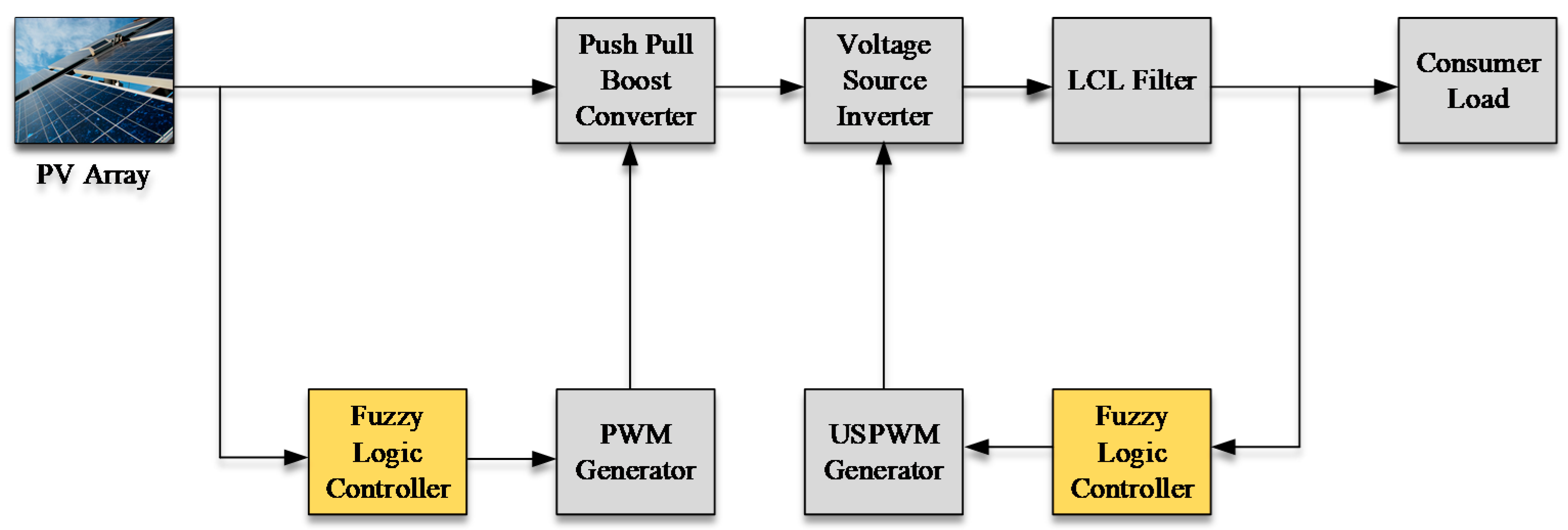
In this paper, a fuzzy logic controller is employed for MPPT to overcome the aforementioned shortcomings by tracking the maximum power point (MPP) in real time. Fuzzy logic based control offers an advantage in that it does not oscillate near the MPP [31,32]. This kind of control is unique for push pull current-fed boost converters where the high frequency transformer is used to provide the galvanic isolation between the input and output side along with a high conversion ratio [33,34]. DC voltage is inverted to AC through a voltage source inverter (VSI) with a fuzzy logic closed loop controller, which improves the power quality of the AC voltage and provides very low THD. In this work, 5% THD is considered, which is tolerable according to the Institute of Electrical and Electronics Engineers (IEEE) standard [35].
The proposed work covers many of the shortcomings mentioned in the introduction section. However, to distinguish the proposed research from the previously published literature, the main contributions of this proposed work are summarized as follows:
  • Design of fuzzy logic based MPPT, which can track the continuous power without oscillations and noise near the maximum point.
  • Implementation of a push pull current-fed boost chopper in which high frequency transformer is used to provide the galvanic isolation between input and output, along with a high conversion ratio.
  • Implementation of a voltage source inverter (VSI) with a fuzzy logic closed loop controller, which improves the power quality of the AC voltage and provides very low THD.
  • Applications of two fuzzy logic controllers (FLCs) are employed in the proposed system and each has its unique fuzzy rule. The first one tracks the MPPT, and the second is used in VSI with a proper designed low pass filter to reduce the THD value.
Furthermore, a comparative section is added at the end, which is based on the literature on the fuzzy logic principle. The comparison includes the methodology used with fuzzy logic, implementation complexity, generalization in terms of symmetrical and asymmetrical membership function, inputs to the membership functions, hardware implementation, noise and oscillations near MPP, THD analysis, and the proper filter design. This comparative analysis also distinguishes the proposed research from the previously published literature. As a result, the proposed work has advantages in term of simple, accurate, and faster convergence to the operating point with minimum noise and THD levels.
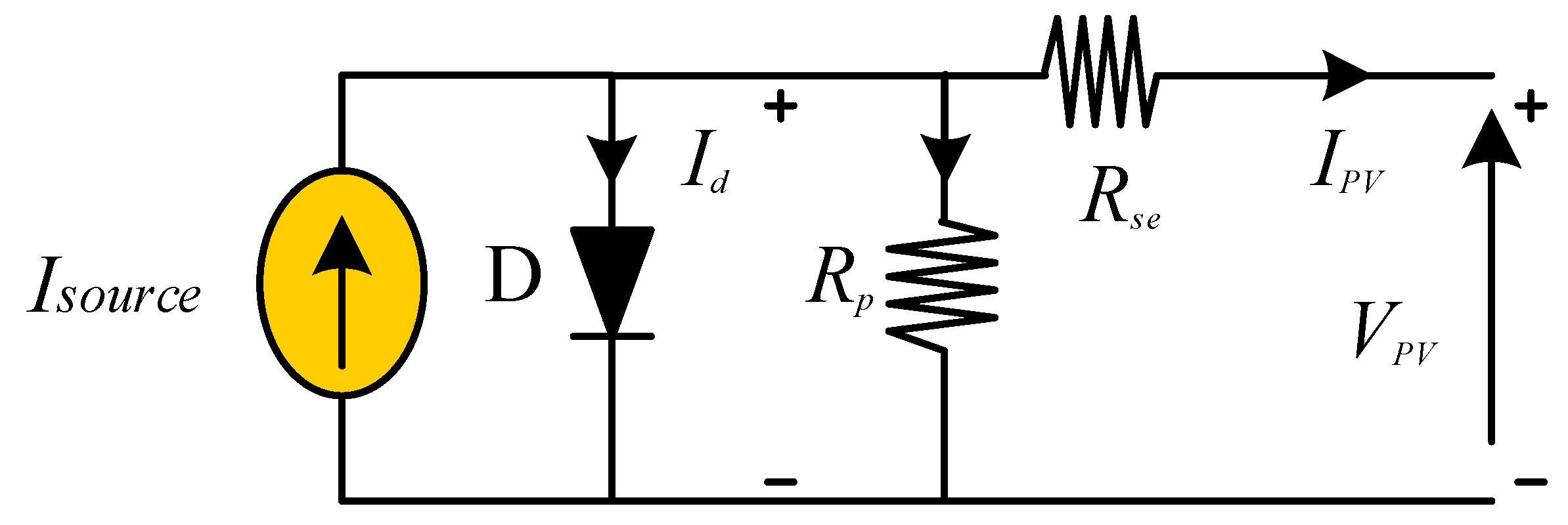
This paper is organized as follows. An equivalent circuit for an individual PV cell based on a single diode model is presented in Section 2 that serves as a basis for MPPT and defines the proposed methodology. The push pull converter and its design aspects are explained in Section 3, while the fuzzy logic based MPPT algorithm is described in Section 4. Furthermore, the push pull converter, VSI, and low pass filter design are explained in Section 4. Simulation results and discussions are in Section 5 and, finally, the conclusions are drawn in Section 6.

2. Proposed Work Methodology

Before discussing the proposed work topology and fuzzy logic control, it is important to elaborate on the equivalent solar circuit.

2.1. Solar Cell Equivalent Circuit

The equivalent circuit of the solar cell is presented in Figure 1 and indicates a current source is connected with parallel diode. Here, Rse is a series resistance, Rp is connected in parallel, while RL is the load resistance. The reverse saturation current of the diode is Is. The resistance RP is very high compared with Rse. The diode anode current and VPV can be obtained as [36] by applying Kirchhoff current law (KCL) to the solar cell equivalent circuit:
I S o u r c e I d V d R p I p v = 0
I d = I s   ( e q V d N K T 1 )
V P V = V d R s e I P V

2.2. Proposed Topology

An isolated photovoltaic system is designed for a 500 W solar panel with a fuzzy logic MPPT algorithm. Fuzzy logic closed loop voltage source inverter and low pass filter are employed. Figure 2 shows the proposed system components. Both the voltage and current of the solar PV array are measured to calculate the power. On the basis of the present and previous values of power and current, error and change in error are computed for the fuzzy logic controller that gives the fuzzy rules. On the basis of these fuzzy rules, the fuzzy logic controller sets the duty ratio for pulse width modulation (PWM), 40 kHz triangular wave is compared with the fuzzy logic controller output. The PWM generator produces the switching signal for push pull boost converter switches (which are insulated-gate bipolar transistors (IGBTs)). The push pull boost converter boosts the 60 V DC to 340 V DC. Then, the DC voltages are inverted into 220 V AC through voltage source inverter (VSI). The low pass filter removes the high frequency harmonic content. The switching of VSI is performed through the unipolar sinusoidal pulse width modulation (USPWM) generator and the unipolar switching technique is employed to mitigate the low order harmonic contents.

2.3. Fuzzy Logic Control

In the fuzzy logic MPPT algorithm, voltage and current at each instant k are sensed to calculate the active power [31]. The active power is then compared with the power at last instant k − 1 to obtain the change in power (ΔP(k)). Similarly, the current at instant k is compared with the current at instant k − 1 to achieve the current error (ΔI(k)). Afterwards, the power error is divided by the current error to achieve the error (e), which is compared with the previous error to calculate the change in error (Δe(k)) as in Equations (4) and (5), respectively. In this way, error e(k) and Δe(k) become the crisp inputs of the fuzzy logic controllers. The flow chart for fuzzy logic MPPT is shown in Figure 3.
In this work, Mamdani inference technique, A-type membership functions, and 49-element rule base were used for the fuzzy logic control because of the fact that Mamdani inference technique is efficient and straightforward in defining the fuzzy output sets and is more popular among researchers than other inference techniques [37]. The A-type or triangular type membership function is used because it has fewer complexities when splitting values (low, med, and high (Membership Function) MF) comparing other membership functions. Moreover, it was observed that the triangle membership function gives the faster response and less overshoot than others [38]. The 49-element rule base was employed because it exhibits good performance [39,40].
e ( k ) = Δ P ( k ) Δ I ( k ) = P ( k ) P ( k 1 ) I ( k ) I ( k 1 )
Δ e ( k ) = e ( k ) e ( k 1 )
Generally, a fuzzy logic controller consist of three components: (i) fuzzifier, (ii) inference, and (iii) defuzzifier [41]. Each component is individually described below.

2.3.1. Fuzzifier

This component of the fuzzy logic controller receives the data from the input and analyzes them according to the user user-defined chart called membership function. Fuzzifier receives the data in the non-linear form and assigns them grade from 0 to 1. Membership functions have different shapes. These shapes depend on the type of data, and but the common shapes are S, π, A, and Z [30]. ‘A’ shape has been used in this work for fuzzification operation.

2.3.2. Interference

The inference system consists of a fuzzy rule plays an important role in representing the expert control or modeling knowledge between the input and output side. In the literature, different techniques are used in the inference system. Mamdani inference technique with the fuzzy rule is employed in this work. If-then else statements are used in the system for fuzzy inference [42]. For example, we consider a simple two-input one-output example that has three fuzzy rules.
Rule (1)
IF X is A2 OR Y is B1 Then Z is C1
Rule (2)
IF X is A2 AND Y is B2 Then Z is C3
Rule (3)
IF X is A1 Then Z is C3
The fuzzy logic membership functions designer, fuzzy logic rule editor, fuzzy logic rules, fuzzy logic member ship function input error, change in error, and membership function output are shown below in Figure 4, Figure 5, Figure 6 and Figure 7.
The following are the fuzzy rules in Table 1, which are used for desired MPP of push pull converter PWM.

2.3.3. Defuzzification

In the defuzzification process, fuzzy logic controllers use the fuzzy rules to obtain the output value. This output value of the fuzzy logic controller depends upon the method of defuzzification. Hence, it is the gained value of a fuzzy logic controller with respect to the label value in the fuzzy logic membership function. Seven fuzzy membership functions were used in this research, as enlisted in Table 1. These seven functions are negative big (NB), negative medium (NM), negative small (NS), zero (ZE), positive small (PS), positive medium (PM), and positive big (PB). During the defuzzification, the FLC converts the fuzzy logic value into a data value. Numerous methods are available for the defuzzification process such as the average weight (AW) method, center of gravity (COG), mean of maximum (MOM), and smallest of maximum (SOM) [30]. The COG method is used for MPPT in which all fuzzy values are converged at one point [26]. The fuzzy logic rules are used in the push pull boost converter design for MPPT, which is given in Table 1 [42].

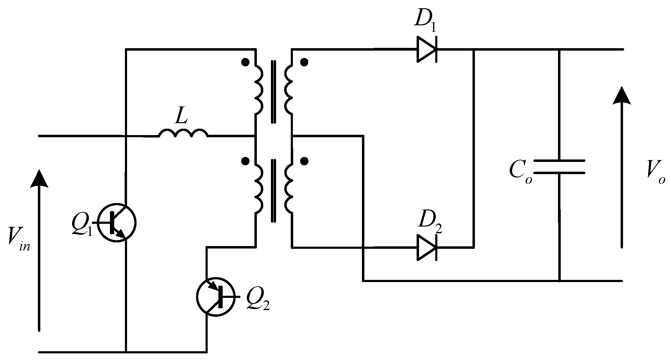
3. Push Pull Converter and Its Design Aspects

The push pull converter consists of a centrally tapped transformer, two push pull switches Q1 and Q2, series inductor L, two rectifier diodes D1 and D2, and a parallel capacitor C0, as shown in Figure 7. Push pull converter can operate in four states. By applying PWM, the designed inductor and specifications of load ensure that the converter always operates in the continuous conduction mode (CCM) [36,42].
A designed current fed DC–DC push pull boost converter is shown in Figure 7 and its operating characteristics are given in Table 2.
This circuit consists of a center tap transformer, two push pull switches Q1 and Q2, series inductor L, two rectifier diodes D1 and D2, and a parallel capacitor with the output load.
The turn ratio of the transformer is calculated as follows:
n = 2 V o ( 1 D ) V i n
The switches’ on and off time are selected as follows:
t o n = T 2 ( D 1 2 ) = ( 1 D ) T
t o f f = ( D 1 2 ) T
When both switches are in an off state, the voltage across these switches is double. This voltage stress is compensated by selecting a transformer tapping voltage as follows:
V o 1.05 × V i n , max
During the dead time, when both switches are in the off position, the inductor increases in a linear mode of operation.
V i n = 2 L Δ I t o f f
When only one switch is on, the energy is transferred to the secondary side of the transformer, then
V o = V i n + 2 L Δ I t o n
Hence,
V o = V i n + V i n × t o f f t o n = V i n × 1 2 ( 1 D )
The input current of the inductor with efficiency η is given by the following:
I i = p o η × V d
The inductor size is selected carefully, a very value inductor may cause the converter to operate in the discontinuous mode and very high-value inductor may cause an increase in the size and weight of the converter.
Δ I = x I i
where 0.05 x 0.3 for optimal operation.
V i n = V o × 2 ( 1 D ) = 2 L Δ I t o f f
Rearanging the equation
L Δ I = V o × 2 ( 1 D ) × ( D 1 2 ) T
Or
( Δ I ) max = V c t 16 L f s
The proposed converter operates in CCM; therefore, minimum inductance is required at the output side, which is calculated as represented in Equation (18).
L = V o 16 × f s ( Δ I ) max
To operate the converter in CCM, the value of the output side capacitor is calculated as shown in Equation (19).
C 0 = P o ( 2 D 1 ) 4 V r × V o 2 × f s
where Vr is DC ripple voltage, which is 3% allowable.
The proposed converter topology offers the benefit of isolation between the input and output side, maximum efficiency, constant input current, high voltage conversion, the minimum number of switches, simplicity of configuration, and thus low conduction losses. Furthermore, there is no need for a filter capacitor at the input side that makes the system simple and compact [34].

4. VSI and Low Pass Filter Design

In the proposed system, a single-phase full bridge inverter is used to feed the consumer load, which inverts the 340 V DC into 220 V AC at 50 Hz frequency. The unipolar sinusoidal pulse width modulation (USPWM) technique is used to turn on/off the inverter switches. This technique reduces THD and power losses during switching [26]. In USPWM, two control signals are used: a sinusoidal wave and its 180° out of phase version at 50 Hz. These control signals are compared with high frequency triangular carrier signal of 10 kHz. Control signal 1 is compared with the carrier signal, resulting in a logic signal that generates the output voltage between 0 and +Vdc. Control signal 2 is compared with the carrier signal, resulting in a logic signal that produces the output voltage between 0 and +Vdc. In every inverter, a filter is necessary for improving power quality. Therefore, a low pass filter is used for smoothing the output current from VSI. The LCL filter is shown in Figure 8.
The components of the filter are obtained as represented in Equations (20)–(25).
The filter value refers to base impedence
Z b = E   n 2 P n = V 0 2 P n
where Zb is the base impedance and V0 and Pn are the output voltage and power of the inverter, respectively. The maximum power variation is considered as 5% and the base impedance is adjusted as computed in Equation (21):
C f = 0.05   C b
where L1 is inductance on inverter side. For 10% ripple, L1 is calculated by considering the rated current of the inductor.
Δ   I   L max = 0.1   I max
Further, Imax is calculated as shown in Equation (23):
I max = P n V o
L1 is calculated as represented in Equation (24):
L 1 = V d c 16   f s   Δ I L max
where fs is switching frequency and L2 is calculated as follows:
L 2 = 1 K a 2   +   1 C f   ω   s 2
where Ka is the attenuation factor and is taken as Ka = 0.2, while ωs = 2πfs is angular switching frequency [41,43].
For LCL filter, derived parameters are L1 = 9.3 mH, L2 = 37.5 mH, and 
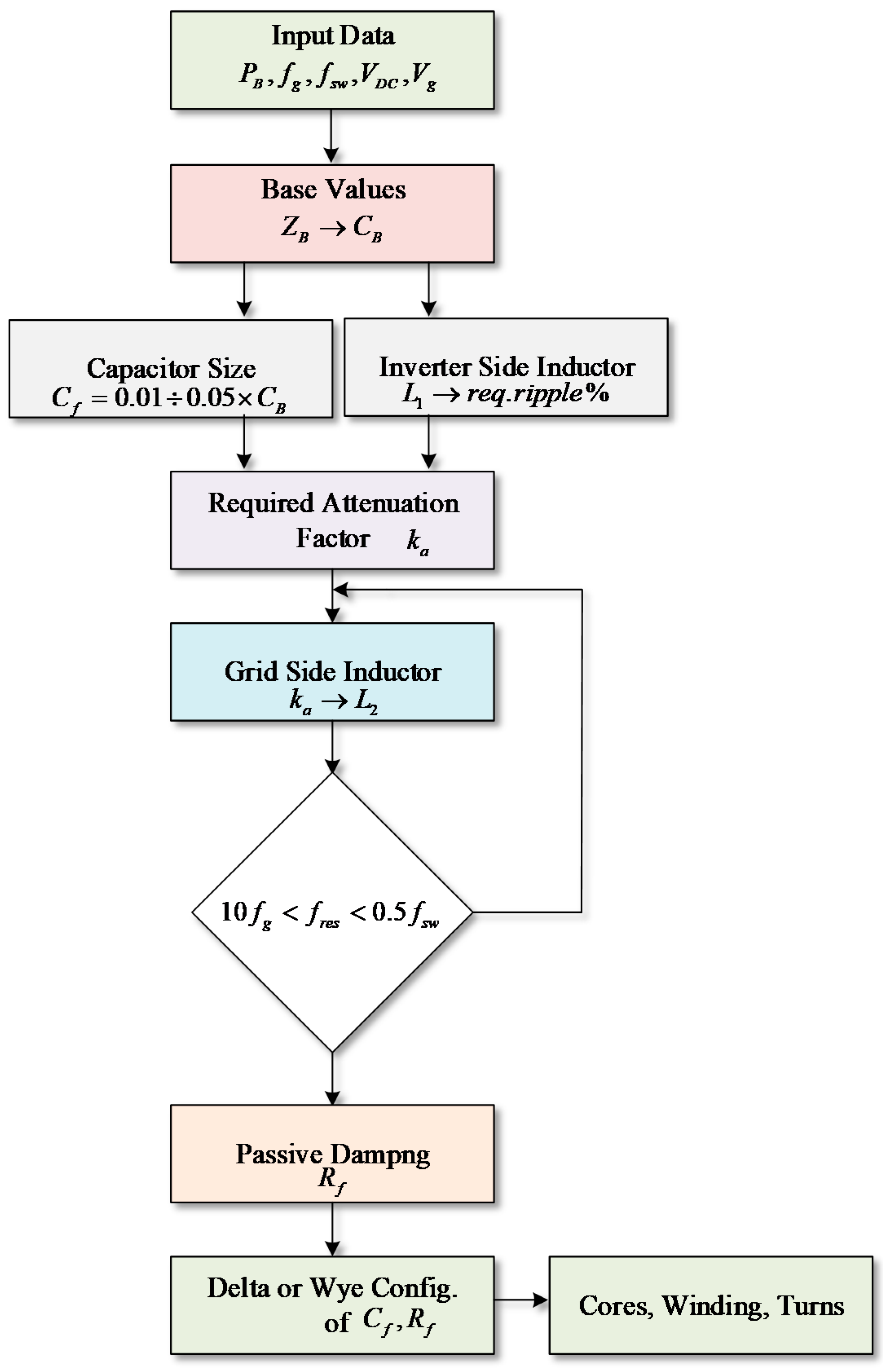
C = 1.6 μF with the unity power factor. The LCL filter designing algorithm is shown in Figure 9. After the filtration, (root mean square) RMS output voltages are sensed for the fuzzy logic controller input. The output of the controller is compared with the sinusoidal AC voltages at the fundamental frequency, and then PWM set the duty of VSI.
The fuzzy logic structure of VSI is the same as the MPP push pull converter; however, the fuzzy rules used in FLC of VSI are listed in Table 3.

5. Results and Discussion

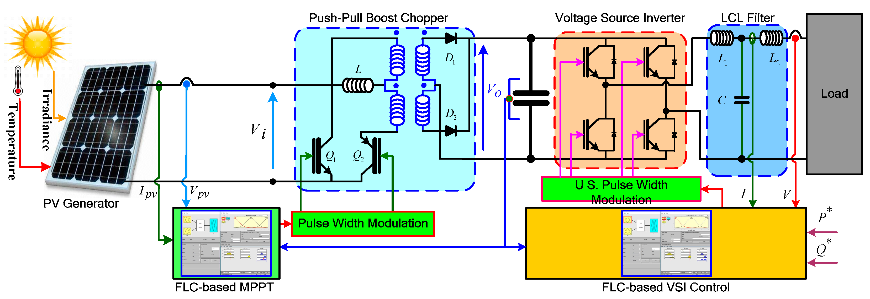
The proposed isolated photovoltaic system with a fuzzy logic controller, the current fed push pull DC–DC boost converter, is presented here. The DC–DC boost converter operates in continuous conduction mode, and the voltage source inverter with fuzzy logic closed loop and low pass filter are simulated in Matlab/Simulink. The parameters of the employed PV array (Canadian solar CS5P 250-M) are given in Table 4. The performance of the developed system is tested at different irradiance intensity at 25 °C and a linear load of 200 Ω, as shown in Figure 10. Voltage and current are sensed to calculate the power.
In the first case, the system is simulated at a constant temperature of 25 °C and constant irradiance 1000 W/m2. It tracks the maximum power 250 W in a very small amount of time, approximately 0.005 s, as shown in Figure 11.
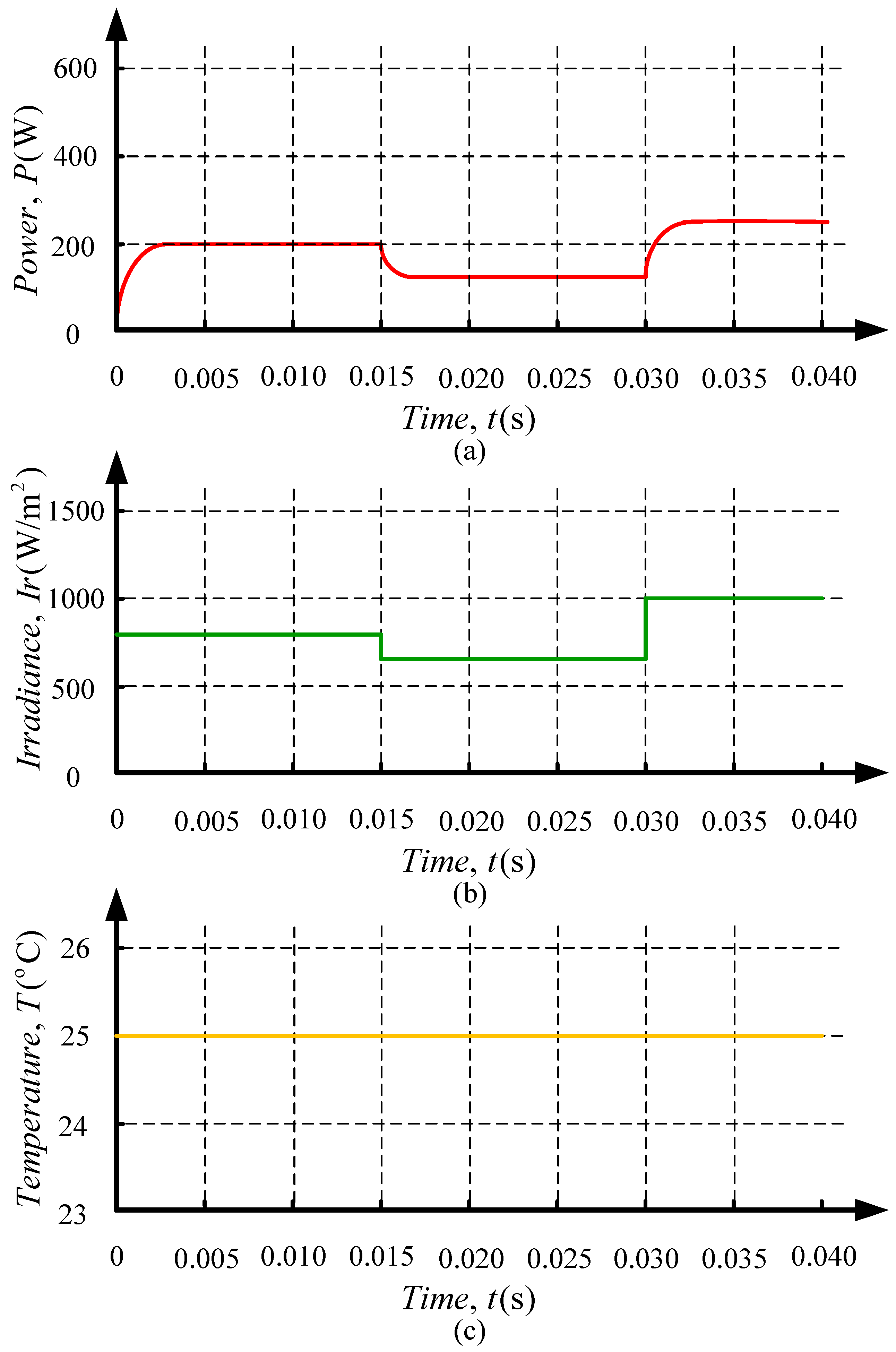
In the second case, the system is simulated for various irradiance levels as follows: 800 W/m2 for 0.015 s, 600 W/m2 for 0.03 s, and 1000 W/m2 for the rest of the time. In this scenario, it again tracks the maximum power point within the same designed spam of time (0.005 s) and gives the power of 200 W, 150 W, and 250 W, respectively, as shown in Figure 12. This power is tracked through the fuzzy logic controller, where fuzzy rules are employed as given in Table 1.
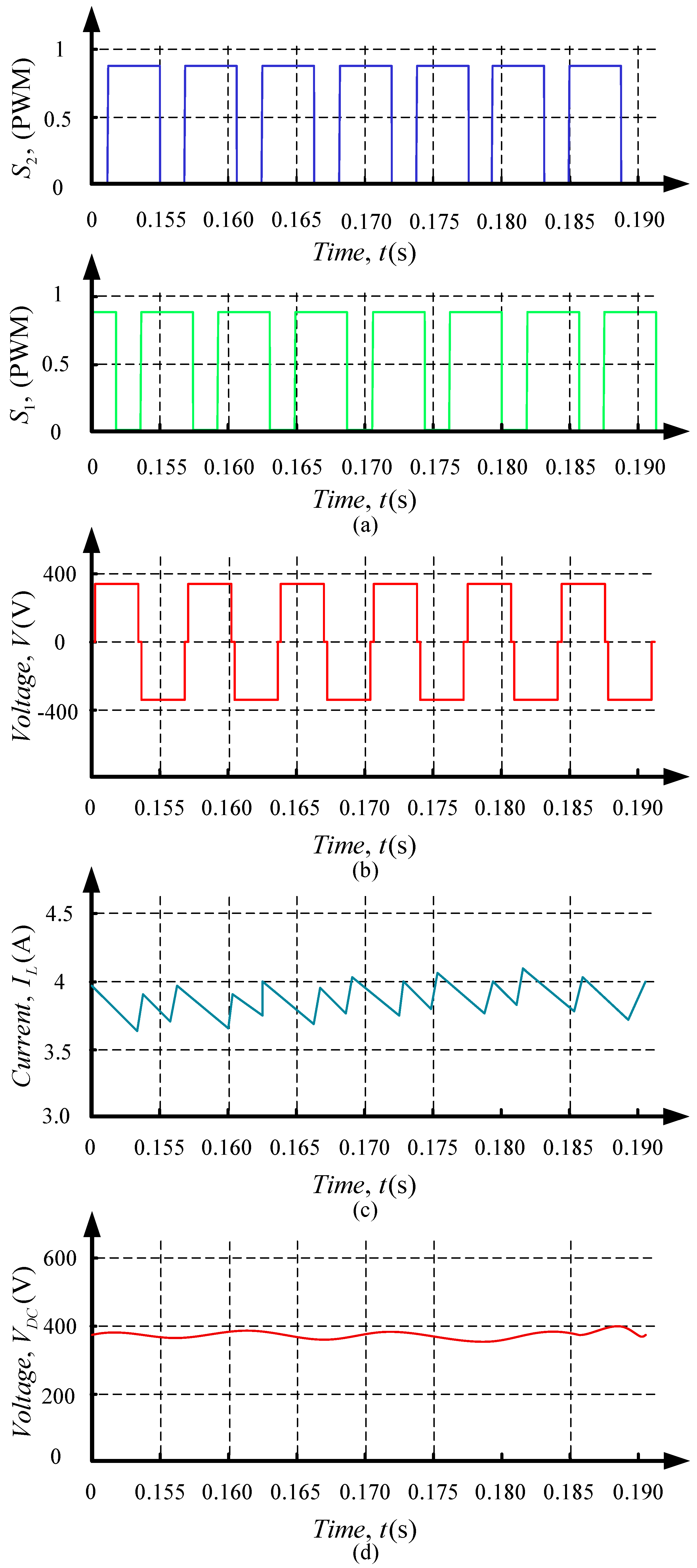
On the basis of the designed fuzzy rules, the fuzzy logic controllers generate the fuzzy logic PWM and decide what would be the duty ratio of the push pull boost converter switches shown in Figure 13a. The push pull boost converter operates in four states. In state 1, when the switch Q1 is on, then the inductor would discharge, and output voltage would be positive. In state 2, switches Q1 and Q2 are ON simultaneously. During state 2, the inductor is charged, as shown in Figure 13c, that is, 4.3 A current flows, and the output voltage would be zero because the flux generated in both windings cancels each other out. In this state, the output capacitor provides the voltage to the load, which means that the capacitor would be discharged. In state 3, when the switch Q2 is ON, then the voltage would be negative. Similarly, in state 4, both switches are ON simultaneously for zero output voltages, as shown in Figure 13b, that is, modified sine wave voltages, which are converted into 340 V DC through the rectifier diodes D1 and D2, as shown in Figure 13d.
The DC voltages are inverted into 220 V AC through the VSI. These voltages are sensed through the voltage sensor and compared with the sinusoidal AC voltages; error and change in error are calculated for fuzzy FLC. This controller generates the reference signal for the PWM generator, which operates the inverter switches and is operated according to the fuzzy logic controller. The PWM of the inverter is shown in Figure 14a. FLC generates the reference signal by using the fuzzy rules of Table 3, settled down by removing the lower order harmonic content in AC voltages. However, these voltages still have the higher-order harmonic content shown in 
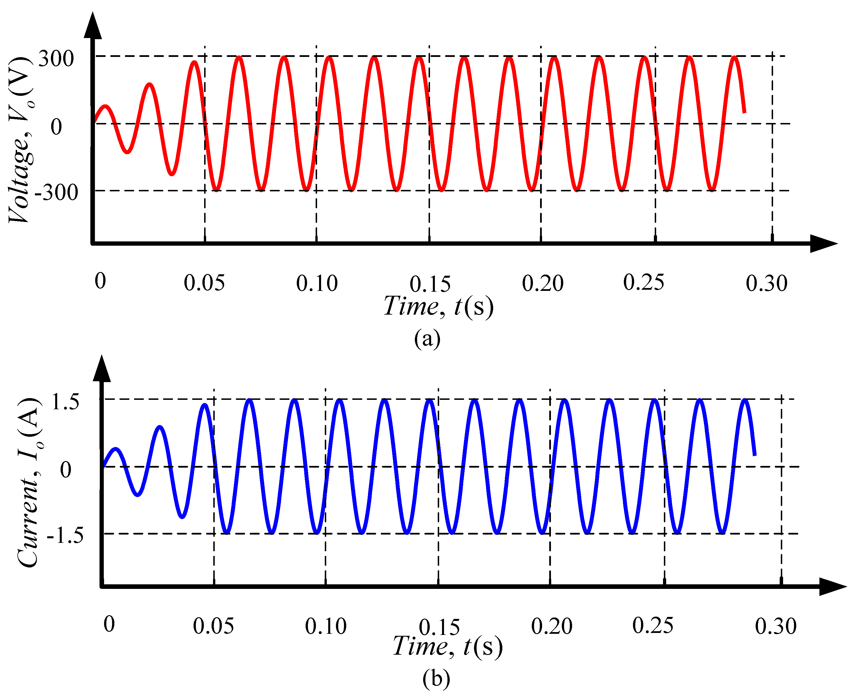
Figure 14b. The higher-order harmonic contents are removed through the low pass filter. The output voltages and current of inverter after removing the higher-order harmonic content are shown in Figure 15, where Figure 15a presents the AC voltages and Figure 15b shows the AC current, which is 1.5 A.
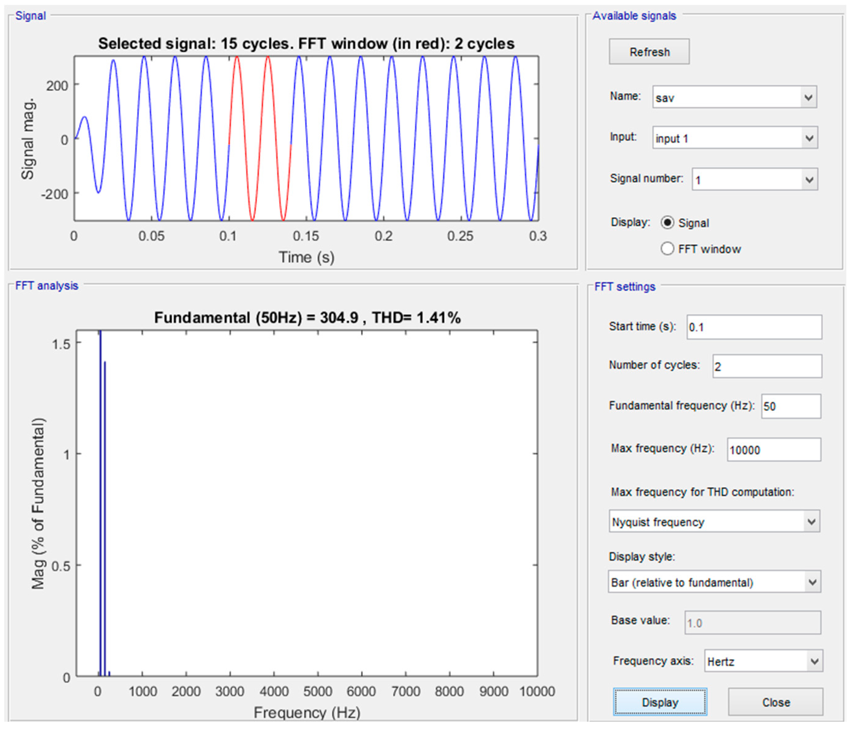
To check the quality of output voltages and current, the fast Fourier transform (FFT) analysis is also carried out and obtained THD are shown in Figure 16 and Figure 17. The FFT analysis of the proposed algorithm provides only 1.41% THD for output voltage and current at 50 Hz.
To prove the validity of the conducted research, a comparison between the results of the fuzzy logic-based MPPT algorithm is compared with P&O and incremental conductance algorithms available in the literature, in the time domain function at irradiance 1000 W/m2 and at 25 °C, as listed in Table 5.

Comparative Analysis

In this section, a comparative analysis is performed, which is represented in Table 6. The comparative analysis is based on the literature on the fuzzy logic principle. The comparison includes the methodology used with fuzzy logic, implementation complexity, generalization in terms of symmetrical and asymmetrical membership function, inputs to the membership functions, hardware implementation, noise and oscillations near MPP, THD analysis, and the proper filter design. This comparative analysis also distinguishes the proposed research from the previous published literature. As a result, the proposed work has advantages in terms of simple, accurate, and faster convergence to the operating point with minimum noise and THD.

6. Conclusions

In this paper, an off-grid photovoltaic system with a fuzzy logic MPPT-controlled push pull boost converter is designed. The proposed system is simulated in Matlab/Simulink and tested for various weather conditions. The results proved the efficiency of the fuzzy logic algorithm, which ouperforms the conventional algorithms in terms of MPPT accuracy and minimization of fluctuations, regardless of irradiance rapid changes. In addition, the fuzzy logic-based controller designed for the VSI and the adopted LCL filter allow to achieve high performance. The proposed interfacing system between the PV generator and the load is very effective because the provided total harmonic distortion (THD) is 1.41%, which is in agreement with the IEEE standard at the operating frequency.

Author Contributions

Conceptualization, T.-u.H., and F.A.; methodology, F.A.; software, F.A. and K.M.C.; validation, F.A., formal analysis, M.F.T.; investigation, M.F.T.; resources, M.F.T. and K.M.C.; data curation, F.T.; writing—original draft preparation, K.M.; writing—review and editing, K.M., R.A. and H.J.; visualization, I.A.K. and R.M.E.; supervision, T.-u.H.; project administration, T.-u.H.; Funding acquisition, R.A. and H.J. All authors have read and agreed to the published version of the manuscript.

Funding

This research received no external funding.

Conflicts of Interest

The authors declare no conflict of interest.

References

  1. Tahir, M.F.; Haoyong, C.; Mehmood, K.; Ali, N.; Bhutto, J.A. Integrated energy system modeling of China for 2020 by incorporating demand response, heat pump and thermal storage. IEEE Access 2019, 7, 40095–40108. [Google Scholar] [CrossRef]
  2. Tahir, M.F.; Haoyong, C.; Khan, A.; Javed, M.S.; Laraik, N.A.; Mehmood, K. Optimizing size of variable renewable energy sources by incorporating energy storage and demand response. IEEE Access 2019, 7, 103115–103126. [Google Scholar] [CrossRef]
  3. Cheema, K.M. A comprehensive review of virtual synchronous generator. Int. J. Electr. Power Energy Syst. 2020, 120, 106006. [Google Scholar] [CrossRef]
  4. Tahmasebi, H. Boost Integrated High Frequency Isolated Half-Bridge DC-DC Converter: Analysis, Design, Simulation and Experimental Results; University of Victoria Libraries: Victoria, BC, Canada, 2015. [Google Scholar]
  5. Dolara, A.; Faranda, R.; Leva, S. Energy comparison of seven MPPT techniques for PV systems. J. Electromagn. Anal. Appl. 2009, 2009, 725. [Google Scholar] [CrossRef] [Green Version]
  6. Tahir, M.F.; Chen, H.; Javed, M.S.; Jameel, I.; Khan, A.; Adnan, S. Integration of different individual heating scenarios and energy storages into hybrid energy system model of China for 2030. Energies 2019, 12, 2083. [Google Scholar] [CrossRef] [Green Version]
  7. Alquthami, T.; Butt, S.E.; Tahir, M.F.; Mehmood, K. Short-term optimal scheduling of hydro-thermal power plants using artificial bee colony algorithm. Energy Rep. 2020, 6, 984–992. [Google Scholar]
  8. Khan, I.; Li, Z.; Xu, Y.; Gu, W. Distributed control algorithm for optimal reactive power control in power grids. Int. J. Electr. Power Energy Syst. 2016, 83, 505–513. [Google Scholar] [CrossRef]
  9. Bhattacharjee, V.; Khan, I. A non-linear convex cost model for economic dispatch in microgrids. Appl. Energy 2018, 222, 637–648. [Google Scholar] [CrossRef] [Green Version]
  10. Khan, I.; Xu, Y.; Sun, H.; Bhattacharjee, V. Distributed optimal reactive power control of power systems. IEEE Access 2017, 6, 7100–7111. [Google Scholar] [CrossRef]
  11. Khan, I.; Xu, Y.; Kar, S.; Sun, H. Compressive sensing-based optimal reactive power control of a multi-area power system. IEEE Access 2017, 5, 23576–23588. [Google Scholar] [CrossRef]
  12. Li, Z.; Mehmood, K.; Zhan, R.; Yang, X.; Qin, Y. Voltage-current double loop control strategy for magnetically controllable reactor based reactive power compensation. In Proceedings of the 2019 IEEE Sustainable Power and Energy Conference (iSPEC), Beijing, China, 20–24 November 2019; pp. 825–830. [Google Scholar]
  13. Mehmood, K.; Hassan, H.T.U.; Raza, A.; Altalbe, A.; Farooq, H. Optimal Power generation in energy-deficient scenarios using bagging ensembles. IEEE Access 2019, 7, 155917–155929. [Google Scholar] [CrossRef]
  14. FaizanTahir, M. Optimal load shedding using an ensemble of artificial neural networks. Int. J. Electr. Comput. Eng. Syst. 2016, 7, 39–46. [Google Scholar]
  15. Muhammad Faizan, T.; Chen, H.; Kashif, M.; Noman Ali, L.; Asad, K.; Muhammad Sufyan, J. Short term load forecasting using bootstrap aggregating based ensemble artificial neural network. Recent Adv. Electr. Electron. Eng. 2019, 12, 1–11. [Google Scholar] [CrossRef]
  16. Li, J.; Wang, H. Maximum power point tracking of photovoltaic generation based on the fuzzy control method. In Proceedings of the 2009 International Conference on Sustainable Power Generation and Supply, Nanjing, China, 6–7 April 2009; pp. 1–6. [Google Scholar]
  17. Priyadarshi, N.; Padmanaban, S.; Mihet-Popa, L.; Blaabjerg, F.; Azam, F. Maximum power point tracking for brushless DC motor-driven photovoltaic pumping systems using a hybrid ANFIS-FLOWER pollination optimization algorithm. Energies 2018, 11, 1067. [Google Scholar] [CrossRef] [Green Version]
  18. Kebir, T.; Filiz, G.; Larbes, C.; Ilinca, A.; Obeidi, T.; Tchoketch Kebir, S. Study of the intelligent behavior of a maximum photovoltaic energy tracking fuzzy controller. Energies 2018, 11, 3263. [Google Scholar] [CrossRef] [Green Version]
  19. Priyadarshi, N.; Ramachandaramurthy, V.K.; Padmanaban, S.; Azam, F. An ant colony optimized MPPT for standalone hybrid PV-wind power system with single Cuk converter. Energies 2019, 12, 167. [Google Scholar] [CrossRef] [Green Version]
  20. Wang, Y.; Yang, Y.; Fang, G.; Zhang, B.; Wen, H.; Tang, H.; Fu, L.; Chen, X. An advanced maximum power point tracking method for photovoltaic systems by using variable universe fuzzy logic control considering temperature variability. Electronics 2018, 7, 355. [Google Scholar] [CrossRef] [Green Version]
  21. Ma, S.; Chen, M.; Wu, J.; Huo, W.; Huang, L. Augmented nonlinear controller for maximum power-point tracking with artificial neural network in grid-connected photovoltaic systems. Energies 2016, 9, 1005. [Google Scholar] [CrossRef] [Green Version]
  22. Li, C.; Chen, Y.; Zhou, D.; Liu, J.; Zeng, J. A high-performance adaptive incremental conductance MPPT algorithm for photovoltaic systems. Energies 2016, 9, 288. [Google Scholar] [CrossRef] [Green Version]
  23. Piegari, L.; Rizzo, R.; Spina, I.; Tricoli, P. Optimized adaptive perturb and observe maximum power point tracking control for photovoltaic generation. Energies 2015, 8, 3418–3436. [Google Scholar] [CrossRef]
  24. Cheema, K.M.; Mehmood, K. Improved virtual synchronous generator control to analyse and enhance the transient stability of microgrid. IET Renew. Power Gener. 2020, 14, 495–505. [Google Scholar] [CrossRef]
  25. Yau, H.-T.; Wu, C.-H. Comparison of extremum-seeking control techniques for maximum power point tracking in photovoltaic systems. Energies 2011, 4, 2180–2195. [Google Scholar] [CrossRef]
  26. Salas, V.; Olias, E.; Barrado, A.; Lazaro, A. Review of the maximum power point tracking algorithms for stand-alone photovoltaic systems. Sol. Energy Mater. Sol. Cells 2006, 90, 1555–1578. [Google Scholar] [CrossRef]
  27. Srndovic, M.; Familiant, Y.L.; Grandi, G.; Ruderman, A. Time-domain minimization of voltage and current total harmonic distortion for a single-phase multilevel inverter with a staircase modulation. Energies 2016, 9, 815. [Google Scholar] [CrossRef] [Green Version]
  28. Dolara, A.; Leva, S. Power quality and harmonic analysis of end user devices. Energies 2012, 5, 5453–5466. [Google Scholar] [CrossRef]
  29. Trubitsyn, A. High Efficiency DC/AC Power Converter for Photovoltaic Applications; Massachusetts Institute of Technology: Cambridge, MA, USA, 2010. [Google Scholar]
  30. Sharaf, F.Y. Designing Power Inverter with Minimum Harmonic Distortion Using Fuzzy Logic Control. 2014. Available online: https://195.189.210.17/handle/20.500.12358/18855 (accessed on 15 June 2020).
  31. Li, J.; Wang, H. A novel stand-alone PV generation system based on variable step size INC MPPT and SVPWM control. In Proceedings of the 2009 IEEE 6th International Power Electronics and Motion Control Conference, Wuhan, China, 17–20 May 2009; pp. 2155–2160. [Google Scholar]
  32. Cheng, P.-C.; Peng, B.-R.; Liu, Y.-H.; Cheng, Y.-S.; Huang, J.-W. Optimization of a fuzzy-logic-control-based MPPT algorithm using the particle swarm optimization technique. Energies 2015, 8, 5338–5360. [Google Scholar] [CrossRef] [Green Version]
  33. Maiti, D.; Mondal, N.; Biswas, S. Design Procedure of a Push Pull Current-Fed DC-DC Converter; Jadavpur University: Kolkata, India, 2010. [Google Scholar]
  34. Blooming, T.M.; Carnovale, D.J. Application of IEEE Std 519-1992 harmonic limits. In Proceedings of the Conference Record of 2006 Annual Pulp and Paper Industry Technical Conference, Appleton, WI, USA, 18–22 June 2006; pp. 1–9. [Google Scholar]
  35. Adhikari, N.; Singh, B.; Vyas, A.L.; Chandra, A. Analysis and design of isolated solar-PV energy generating system. In Proceedings of the 2011 IEEE Industry Applications Society Annual Meeting, Orlando, FL, USA, 9–13 October 2011; pp. 1–6. [Google Scholar]
  36. Singh, S.; Mathew, L.; Shimi, S. Design and simulation of intelligent control MPPT technique for PV module using MATLAB/SIMSCAPE. Int. J. Adv. Res. Electr. Electron. Instrum. Eng. 2013, 2, 4554–4566. [Google Scholar]
  37. Wang, C. A Study of Membership Functions on Mamdani-Type Fuzzy Inference System for Industrial Decision-Making. Master‘s Thesis, Lehigh University, Bethlehem, PA, USA, 2015. [Google Scholar]
  38. Usta, M.A.; Akyazi, Ö.; Altaş, İ.H. Design and performance of solar tracking system with fuzzy logic controller used different membership functions. In Proceedings of the 2011 7th International Conference on Electrical and Electronics Engineering (ELECO), Bursa, Turkey, 1–4 December 2011; pp. II-381–II-385. [Google Scholar]
  39. Mudi, R.K.; Pal, N.R. A robust self-tuning scheme for PI-and PD-type fuzzy controllers. IEEE Trans. Fuzzy Syst. 1999, 7, 2–16. [Google Scholar] [CrossRef] [Green Version]
  40. Shehata, A.; Metered, H.; Oraby, W.A. Vibration control of active vehicle suspension system using fuzzy logic controller. In Vibration Engineering and Technology of Machinery; Springer: Berlin/Heidelberg, Germany, 2015; pp. 389–399. [Google Scholar]
  41. Reznik, A.; Simões, M.G.; Al-Durra, A.; Muyeen, S. $ LCL $ filter design and performance analysis for grid-interconnected systems. IEEE Trans. Ind. Appl. 2013, 50, 1225–1232. [Google Scholar] [CrossRef]
  42. Mendel, J.M. Fuzzy logic systems for engineering: A tutorial. Proc. IEEE 1995, 83, 345–377. [Google Scholar] [CrossRef] [Green Version]
  43. Kahlane, A.; Hassaine, L.; Kherchi, M. LCL filter design for photovoltaic grid connected systems. J. Renew. Energies 2014, 2014, 227–232. [Google Scholar]
  44. Suwannatrai, P.; Liutanakul, P.; Wipasuramonton, P. Maximum power point tracking by incremental conductance method for photovoltaic systems with phase shifted full-bridge dc-dc converter. In Proceedings of the 8th Electrical Engineering/Electronics, Computer, Telecommunications and Information Technology (ECTI) Association of Thailand-Conference 2011, Khon Kaen, Thailand, 17–19 May 2011; pp. 637–640. [Google Scholar]
  45. Rezk, H.; Aly, M.; Al-Dhaifallah, M.; Shoyama, M. Design and hardware implementation of new adaptive fuzzy logic-based MPPT control method for photovoltaic applications. IEEE Access 2019, 7, 106427–106438. [Google Scholar] [CrossRef]
  46. Liu, C.-L.; Chen, J.-H.; Liu, Y.-H.; Yang, Z.-Z. An asymmetrical fuzzy-logic-control-based MPPT algorithm for photovoltaic systems. Energies 2014, 7, 2177–2193. [Google Scholar] [CrossRef] [Green Version]
  47. Ozdemir, S.; Altin, N.; Sefa, I. Fuzzy logic based MPPT controller for high conversion ratio quadratic boost converter. Int. J. Hydrogen Energy 2017, 42, 17748–17759. [Google Scholar] [CrossRef]
  48. Robles Algarín, C.; Taborda Giraldo, J.; Rodríguez Álvarez, O. Fuzzy logic based MPPT controller for a PV system. Energies 2017, 10, 2036. [Google Scholar] [CrossRef] [Green Version]
  49. El Khateb, A.; Abd Rahim, N.; Selvaraj, J.; Uddin, M.N. Fuzzy-logic-controller-based SEPIC converter for maximum power point tracking. IEEE Trans. Ind. Appl. 2014, 50, 2349–2358. [Google Scholar] [CrossRef]
  50. Kottas, T.L.; Boutalis, Y.S.; Karlis, A.D. New maximum power point tracker for PV arrays using fuzzy controller in close cooperation with fuzzy cognitive networks. IEEE Trans. Energy Convers. 2006, 21, 793–803. [Google Scholar] [CrossRef]
  51. Zainuri, M.A.A.M.; Radzi, M.A.M.; Soh, A.C.; Abd Rahim, N. Development of adaptive perturb and observe-fuzzy control maximum power point tracking for photovoltaic boost dc–dc converter. IET Renew. Power Gener. 2013, 8, 183–194. [Google Scholar] [CrossRef]
  52. Alajmi, B.N.; Ahmed, K.H.; Finney, S.J.; Williams, B.W. Fuzzy-logic-control approach of a modified hill-climbing method for maximum power point in microgrid standalone photovoltaic system. IEEE Trans. Power Electron. 2010, 26, 1022–1030. [Google Scholar] [CrossRef]
  53. Tang, S.; Sun, Y.; Chen, Y.; Zhao, Y.; Yang, Y.; Szeto, W. An enhanced MPPT method combining fractional-order and fuzzy logic control. IEEE J. Photovolt. 2017, 7, 640–650. [Google Scholar] [CrossRef]
Figure 1. Equivalent circuit of practical single diode model solar cell.
Energies 13 04007 g001
Figure 2. Block diagram of the proposed methodology. USPWM, unipolar sinusoidal pulse width modulation; PV, photovoltaic.
Energies 13 04007 g002
Figure 3. Fuzzy logic maximum power point tracking (MPPT) flow chart.
Energies 13 04007 g003
Figure 4. Membership function input error. NB, negative big; NM, negative medium; NS, negative small; ZE, zero; PS, positive small; PM, positive medium; PB, positive big.
Energies 13 04007 g004
Figure 5. Membership function change in error.
Energies 13 04007 g005
Figure 6. Membership function output.
Energies 13 04007 g006
Figure 7. Circuit diagram for the current fed push pull boost converter.
Energies 13 04007 g007
Figure 8. Application of LCL filter in PV system.
Energies 13 04007 g008
Figure 9. LCL filter design algorithm.
Energies 13 04007 g009
Figure 10. Schematic of the proposed control architecture of the studied system. VSI, voltage source inverter; FLC, fuzzy logic controller.
Energies 13 04007 g010
Figure 11. Output: (a) Power verses time at; (b) constant irradiance; (c) constant temperature.
Energies 13 04007 g011
Figure 12. Output: (a) Power verses time at; (b) different irradiance and; (c) constant temperature.
Energies 13 04007 g012
Figure 13. Output: (a) Fuzzy logic PWM; (b) transformer output; (c) inductor current; (d) DC output voltage.
Energies 13 04007 g013
Figure 14. Output: (a) Inverter fuzzy logic PWM; (b) output voltage before filter.
Energies 13 04007 g014
Figure 15. Output: (a) Inverter output voltage; (b) output current.
Energies 13 04007 g015
Figure 16. Fast Fourier transform (FFT) analysis of output voltage. THD, total harmonic distortion.
Energies 13 04007 g016
Figure 17. FFT analysis of output current.
Energies 13 04007 g017
Table 1. Fuzzy logic rules for the push pull converter. NB, negative big; NM, negative medium; NS, negative small; ZE, zero; PS, positive small; PM, positive medium; PB, positive big.
InputE
NBNMNSZEPSPMPB
NBZEZEZENBNBNBNM
NMZEZEZENSNMNMNM
NSNSZEZEZENSNSNS
ΔEZENMNSZEZEZEPSPM
PSPSPMPMPSZEZEZE
PMPMPMPMZEZEZEZE
PBPBPBPBZEZEZEZE
Table 2. Design parameters of the push pull converter. PWM, pulse width modulation.
ParametersValues
Power500 W
Input voltage60 V
Output voltage340 V
Turn ratio (n)1:6
Switching frequency40 kHz
Duty cycle0.0523
Inductor518 μH
Output capacitor100 μF
Input Inductor current9.38 A
PWM switching frequency10 KHz
Input DC voltage340 V
Output voltageV rms
Resistive load100 Ω
Table 3. Fuzzy logic rules for the voltage source inverter (VSI).
InputE
NBNMNSZEPSPMPB
NBNBNBNBNBNMNSZE
NMNBNBNBNMNSZEPS
NSNBNBNMNSZEPSPM
ΔEZENBNMNSZEPSPMPB
PSNMNSZEPSPMPBPB
PMNSZEPSPMPBPBPB
PBZEPSPMPBPBPBPB
Table 4. Parameters of photovoltaic (PV) array.
PV ArrayParameters
No. of Cells and Connections96
Open Circuit Voltage59.4 V
Maximum Power Voltage48.7 V
Short Circuit Current5.49 A
Maximum Power Current5.14 A
Maximum Power250.318 W
Diode saturation current2.9177 × 10−11
Diode ideality factor0.93246
Shunt resistance428.442 Ohm
Table 5. Tracking time performance comparison [44]. P&O, perturb and observe; INC, incremental conductance.
MPPT AlgorithmsTracking Time of PV Power
P&O0.300 s
INC0.250 s
Fuzzy Logic0.005 s
Table 6. Comparative analysis of fuzzy logic based MPPT.
Ref.MethodologyImplementationGeneralizationInput MFsHardwareNoise and Oscillations Near MPPTHDProper Filter Design
ProposedDual FL based MPPT with PPCSimpleSym./Asym. membershipΔPI
[45]AFL based MPPTSimpleSym./Asym. membershipΔ(ΔPI)
[46]FL based MPPTComplexAsym. membershipΔPV, Δ(ΔPV)
[32]FL based MPPT with PSOComplexAsym. membershipΔP, ΔV
[47]FL based MPPTComplexSym. membershipΔP, ΔV
[48]FL based MPPTSimpleSym./Asym. membershipΔPt, ΔVt
[49]FL based MPPTSimpleAsym. membershipΔPV, Δ(ΔPV)
[50]FL based MPPTSimpleSym. membershipV, ΔV
[51]FL + P&O MPPTComplexSym. membershipΔP, ΔI
[52]FL + HC MPPTComplexAsym. membershipΔPV, Δ(ΔPV)
[53]FL + FO MPPTComplexSym. membershipΔP, ΔI

