3.1. Energy Balance
In
Table 6, a summary of results regarding the annual operation of the analyzed system is presented.
In
Table 6, the presented results indicate that the average biomass energy efficiency (BEUF) is rather low, which is the result of the significant heat demand in the CO
2 capture installation. For the BEUF net efficiency, the decrease in comparison with the reference plant for this study is of 10 percentage points. The electrical efficiencies of the analyzed system are also lower than those in the literature (e.g., a 28.2% net annual average in [
81] for medium—80 MW
ch feed—wood chip CHP with a power-to-heat ratio of 1), but the decrease in the net electricity efficiency in comparison with the reference CHP plant without CO
2 capture and utilization in this study is only 5.3 percentage points. It should also be noted that, to keep the same heat and net electrical production, the power-to-heat ratio of the CHP plant changes significantly (from 1.18 in the reference case to 0.48 in the analyzed system), which also strongly affects the technical design of the steam cycle. If geothermal energy would be included in the efficiency calculations, then the net energy utilization factor would be 26.7% and the net electrical efficiency would be 14.2%. The negative CO
2 emissions of 97.56 t CO
2/TJ
ch are similar to those obtained in the case of CHP plants with a calcium-looping CO
2 capture [
23].
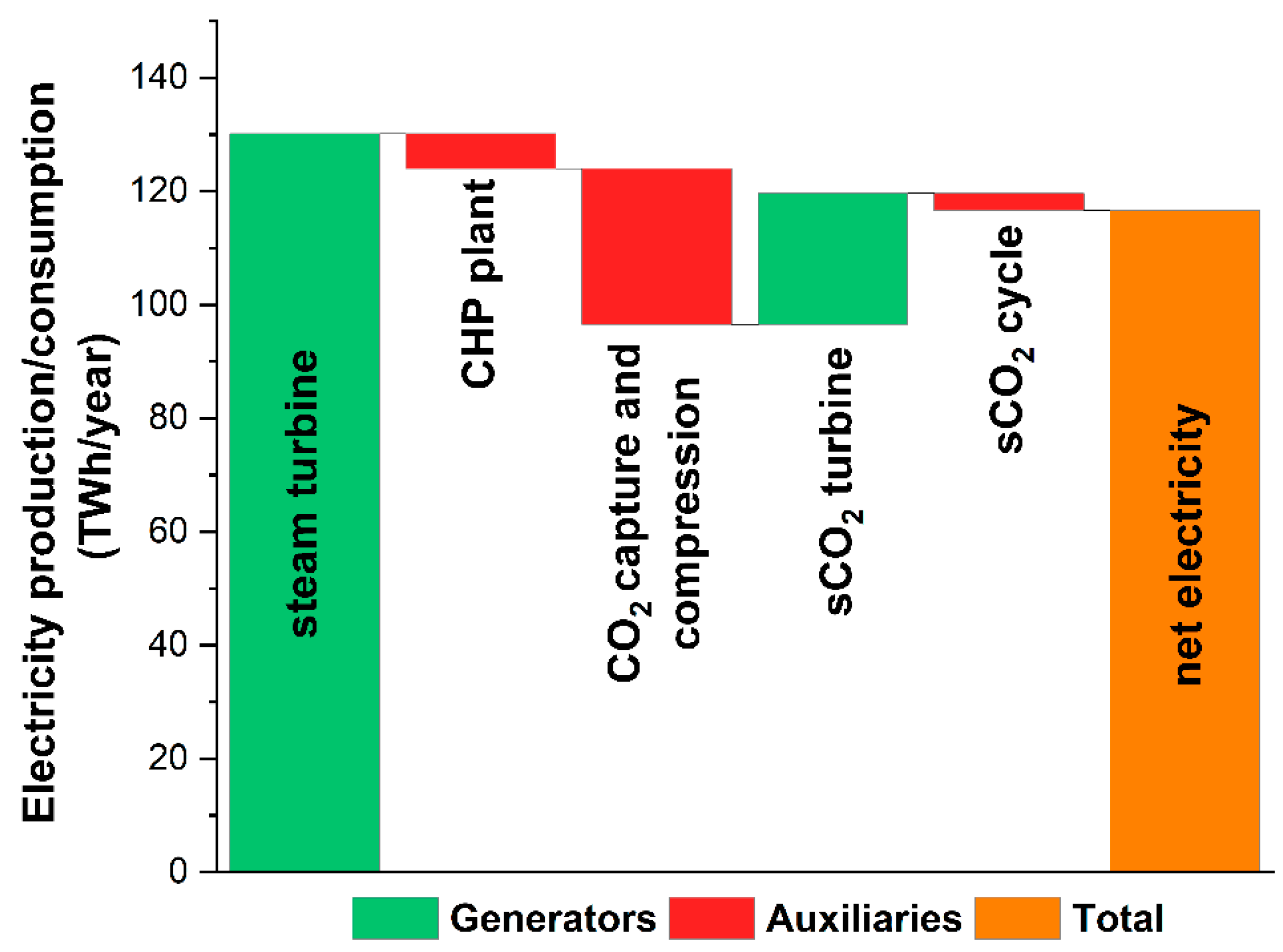
In
Figure 8, the annual electricity balance of the analyzed system is presented. It should be noted that the sCO
2 cycle net electricity generation compensates around 73% of the electricity consumption in the CO
2 capture and compression unit. Thus, from the energy point of view, the CO
2 utilization in EGS instead of conventional storage in saline formations (which would actually require additional electricity, e.g., for brine management [
82]) is more favorable.
The SPECCA for the analyzed system, compared to that for the reference CHP plant (biomass-fired without CCS), is 2.17 MJ
LHV/kg CO
2. When the specific energy consumption for CO
2 avoided includes the geothermal energy, the value increases significantly to 6.22 MJ/kg CO
2. The obtained values of SPECCA, which takes into account only the chemical energy of biomass, can be considered as very low, compared to those for other CO
2 capture technologies (e.g., for MEA, the base case is 3.34 MJ
LHV/kg CO
2 in [
3]). This is a direct result of the heat integration between the CO
2 capture and compression unit and the DHS, as well as the partial compensation of the electricity consumption for CO
2 compression in the sCO
2 power cycle. The system that excludes the CO
2-EGS and assumes conventional CO
2 storage, the SPECCA is equal to 3.41 MJ
LHV/kg CO
2, and is comparable with the values from [
83] for analyzed CO
2 capture technology.
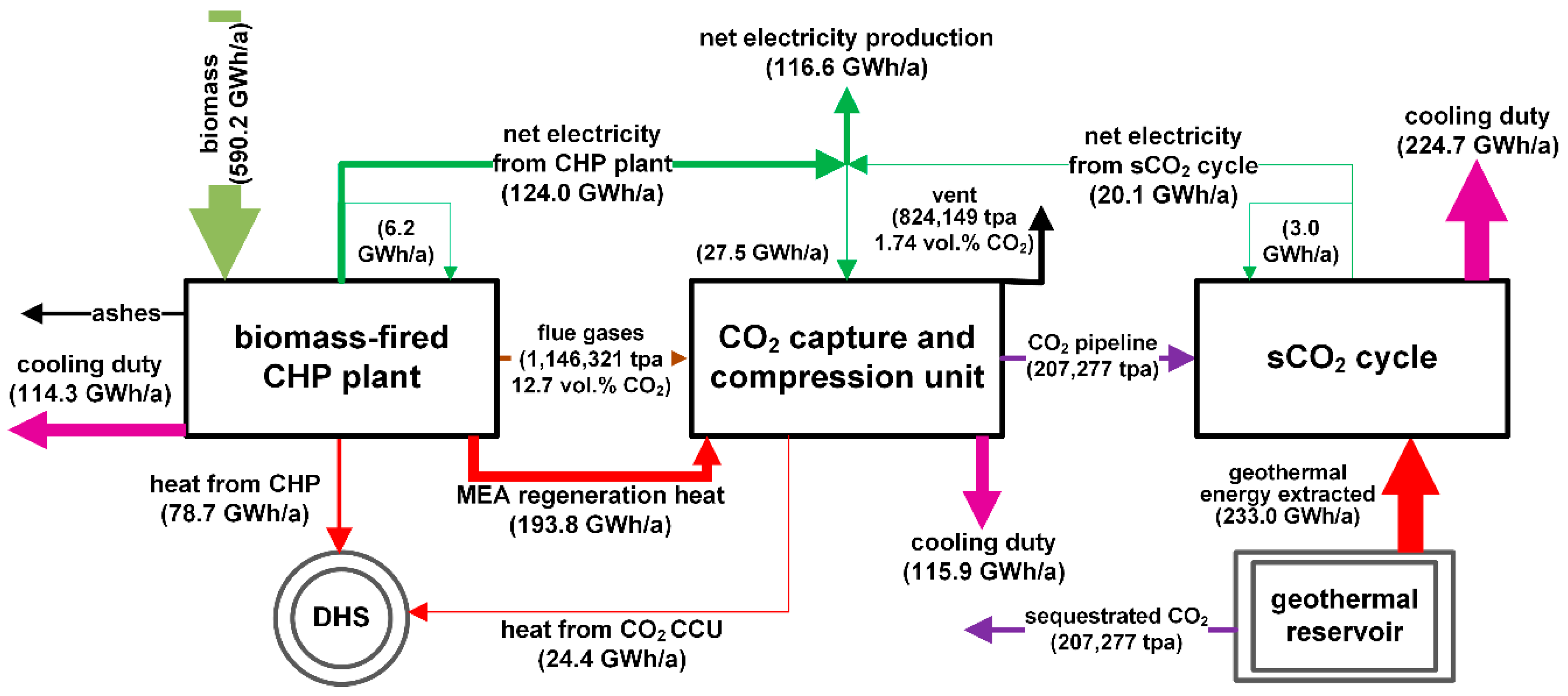
In
Figure 9, the energy balance of the analyzed system is presented, showing the main heat losses (cooling duty), the heat load (both for the DHS and MEA regeneration process heat), and electricity production and consumption. As shown, the main cooling duty is associated with the sCO
2 cycle, where the excess heat is rejected to the environment. It should be noted that rejected heat in the sCO
2 cycle has high parameters (around 110 °C), which means that it could be utilized if possible. It can be also noted that a significant amount of heat is used for MEA regeneration in the CO
2 capture unit, which leads to almost a triplication of the overall heat production in the system compared with the reference plant.
3.2. Economic Evaluation
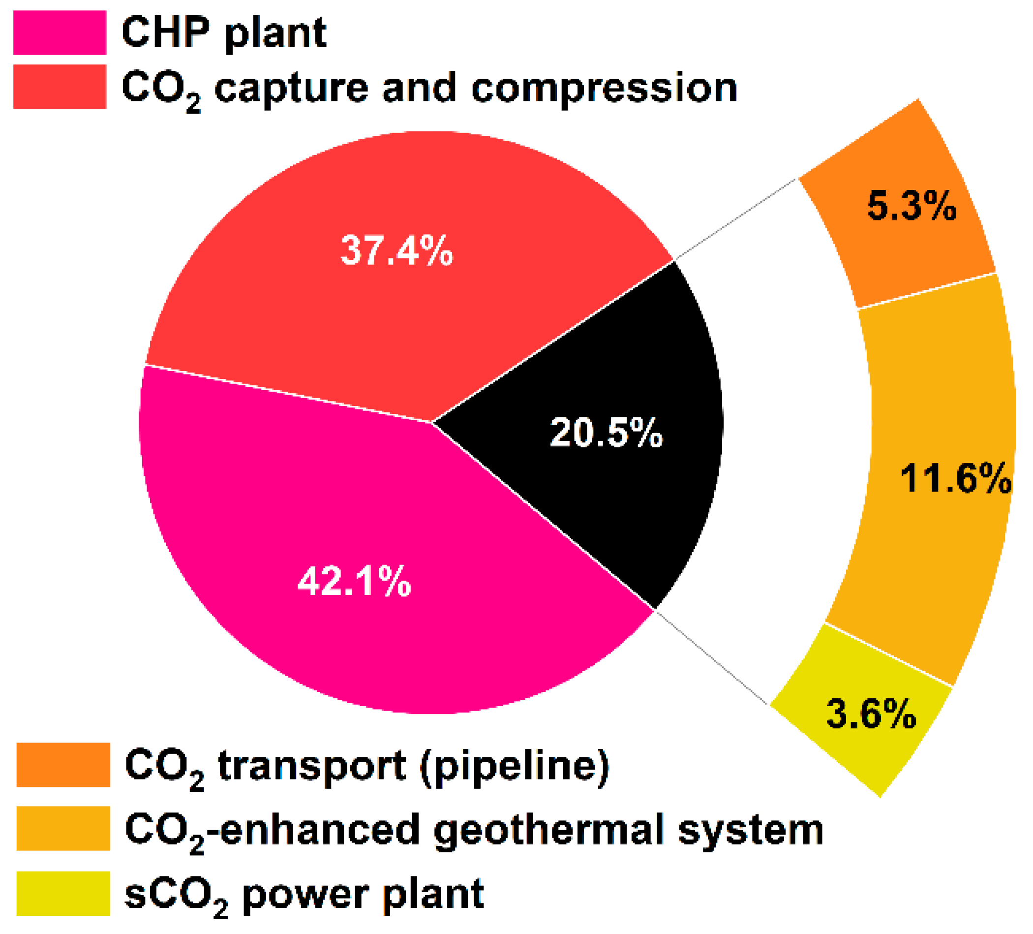
The TSC of the analyzed system was estimated based on Equation (3) and
Appendix B at 153.38 MEUR
2017. In
Figure 10, the share of the TSC for the CHP plant, the CO
2 capture and storage unit, the CO
2 transport pipeline, the CO
2-EGS, and the sCO
2 power plant is presented. As can be seen, the cost of the CO
2 capture and compression plant is nearly double the investment cost of the plant side. The CO
2 transport and utilization (through CO
2-EGS and the sCO
2 power plant) comprise 20.5% of the TSC, where the development (drilling and fracturing) of the CO
2-EGS system is dominant.
The specific unit investment cost was derived from the total subsystem costs, for which the values are as follows:
The biomass-fired CHP plant: 3073 EUR/kWel (gross electric power in full-condensation mode);
The MEA unit and the CO2 compression train: 277.5 EUR/tpa;
The sCO2 power plant and CO2-EGS: 7090 EUR/kWel (gross electric power of the turbine).
In the case of the biomass-fired CHP plant, the values are within the range of medium-size CHP plants fired with wood in the European market, whereas they were 2817 EUR/kW
el in the reference case. For the enhanced geothermal plants, the TSC is almost 100% higher [
84] compared with the conventional geothermal plants. For the CO
2 capture and compression unit, the unit investment costs are also higher (by 30%–50%) when compared with some industrial applications [
85], mainly due to the small scale. Nevertheless, the presented results for the cost estimations will be further used in the economic assessment of the whole system, including in technological development scenarios. Within the analysis, three years of construction time is assumed.
For the analyzed system, in the business as usual scenario, the LCOE is equal to 239.0 EUR/MWh and the LCOH is equal to 9.4 EUR/GJ. When the LCOH is still within an acceptable range, the LCOE is significantly higher than it is in other RES schemes [
84]. However, it should be noted here that none of the other RES schemes analyzed in [
84] have been able to provide negative CO
2 emissions, which is one of the main goals of the proposed system. When the reference CHP plant is considered, the LCOE is 127.5 EUR/MWh and the LCOH is 5.0 EUR/GJ. In
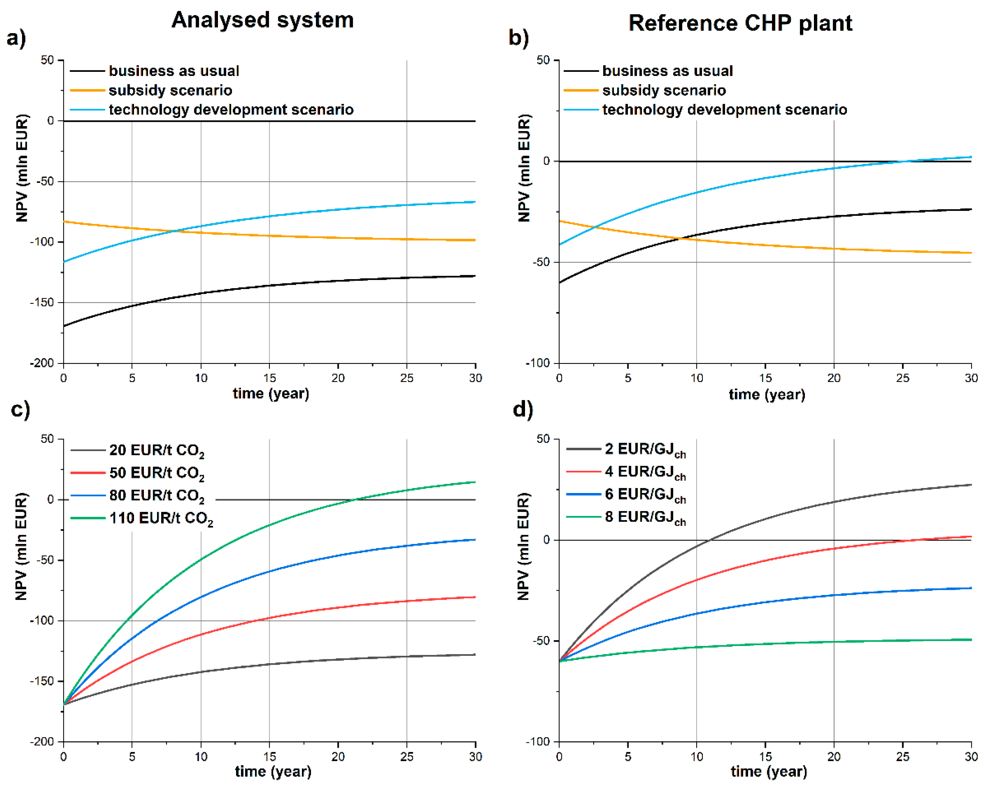
Table 7, the results of the NPV and BEP for all three analyzed scenarios are presented. In all cases, the NPV is below 0, but what is worth mentioning regarding the subsidy scenario (
Figure 11a) is that negative cash flow could be observed—the same comment can be made for the reference CHP plant (
Figure 11b). This means that the subsidy for investment cost, without support for operational costs (e.g., through a feed-in tariff for electricity), does not achieve its purpose. As already mentioned, in the current support system in Poland, a feed-in tariff for electricity and subsidy grants for investment in RES schemes exclude each other to a large degree. In both cases for the analyzed system, the total state subsidy (resulting from a feed-in tariff and investment grants) is around 80 million EUR. As presented in
Table 7, in the investment subsidy scenario, the current feed-in tariff of ca. 100 EUR/MWh would need to be increased by 30% to meet the BEP, which would only allow one to obtain NPV = 0 (and this is still not attractive for potential investors).
In
Figure 11c, the impact of the negative CO
2 emission credit on the NPV for the analyzed system in the business as usual scenario is presented. As there is currently a lack of dedicated schemes to support the negative CO
2 emissions, in the analysis, the corresponding EU-ETS CO
2 emission allowance price was assumed (20 EUR/t CO
2). For the current technological development and economic support mechanism, the price of the negative CO
2 emission credits would need to be five times higher to provide economic justification for investment in the analyzed system. For the reference biomass-fired CHP plant, the impact of the fuel cost on the NPV in the same business as usual scenario has been presented in
Figure 11d. As can be observed, the cost of fuel significantly impacts the economic profitability of the reference CHP plant, and prices below 4 EUR/GJ
ch would be needed to provide economic justification for such units.
In
Table 7, beside the NPV for the analyzed system and reference CHP plant, the results for the BEP price of CO
2 credits, CO
2 avoided cost, and CO
2 negative emission cost are presented. Taking into account their definitions, as expected, the BEP of CO
2 credit is higher than CAC or CNC, as it refers to the overall economic performance of the analyzed system expressed by the NPV. The CAC is higher than CNC, as it refers to the avoided CO
2 emissions, which takes into account the difference in direct CO
2 emissions resulting from fuel combustion in the analyzed system and reference plant. Finally, the CNC refers only to obtained negative emissions, which correspond directly to the amount of CO
2 capture in the analyzed system, as the reference CHP plant CO
2 emission (coming from biomass combustion) is considered to be zero.
As the annual net production of electricity and heat in the analyzed system and reference CHP plant are the same (
Table 6), the lowest CAC was obtained for the investment subsidy scenario, in which the investment cost decreases by 50% (through subsidies), followed by the technology development scenario, where the investment cost decreases by 30% (
Table 5). Thus, the impact of the investment cost on the CAC can be observed. Taking into account the main goal of the proposed system, which is to obtain negative CO
2 emissions, the CNC is a more valuable indicator that quantifies the cost of providing those negative emissions, taking into account the same production levels (in this analysis, electricity and heat) in the energy system. Based on the presented results, it can be stated that the direct cost of negative CO
2 emissions coming from the investment in the proposed CO
2 capture and utilization (and storage) is around 50 EUR/t CO
2, but the economic justification for the development of the analyzed system is two times higher (around 100 EUR/t CO
2) in the business as usual scenario.
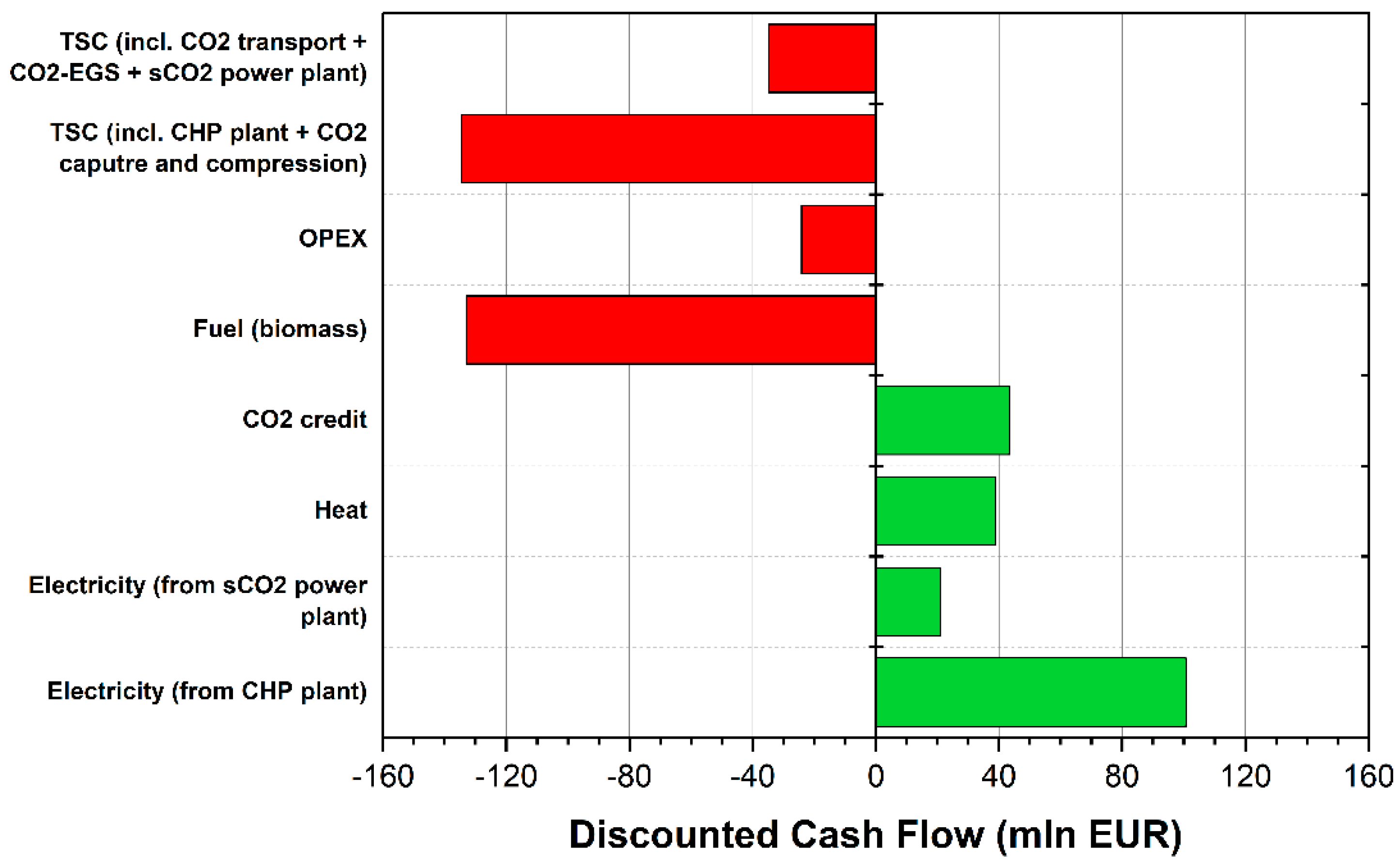
In
Figure 12, the discounted cash flow (CF) for the analyzed system is presented. It can be observed that incomes from electricity and heat barely surpass the operational expenditures (fixed and variable operational costs). Thus, the NPV values (e.g., for the business as usual scenario) correspond to the TSC.
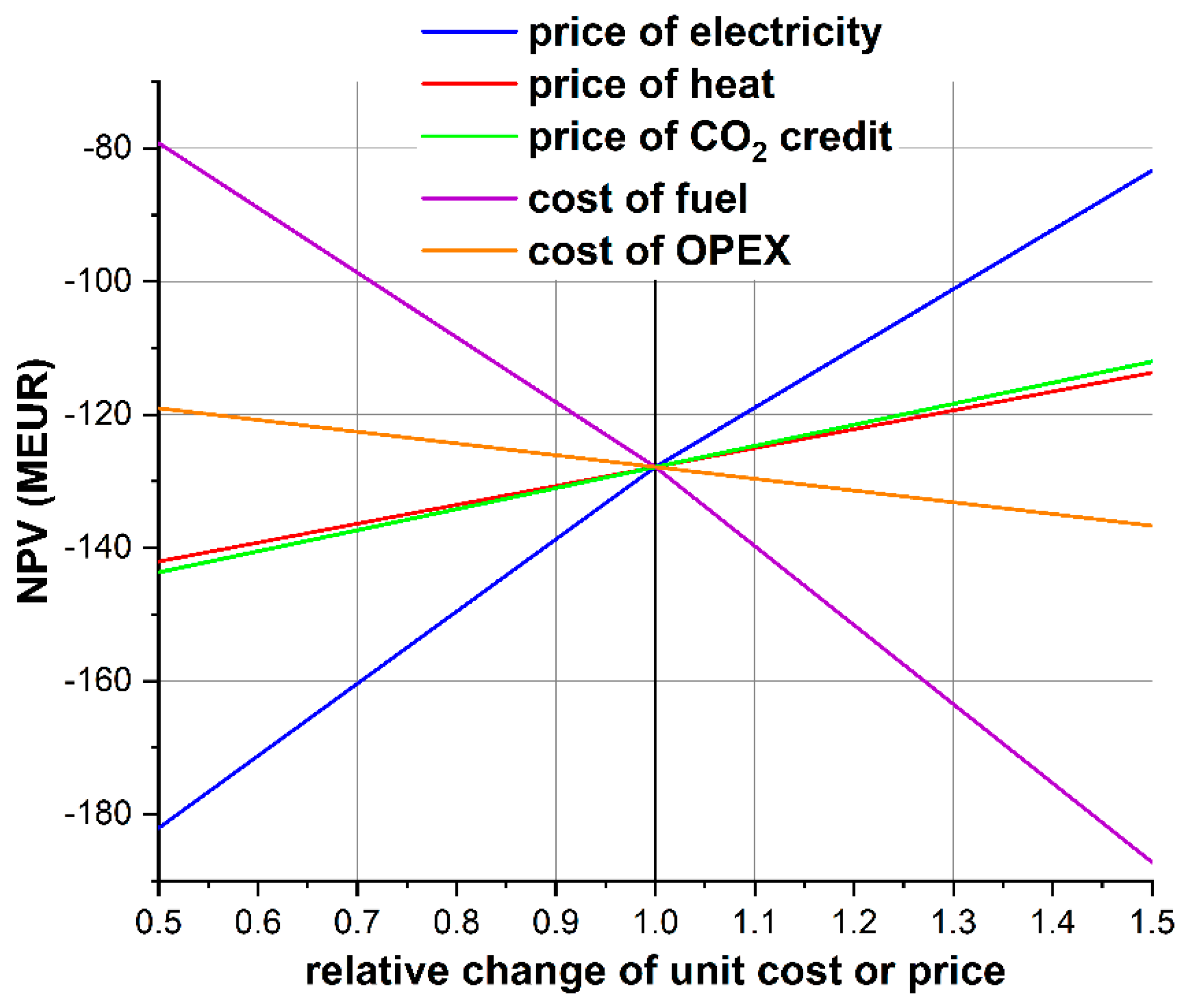
For the performed economic assessment, sensitivity analysis was performed, and the results are presented in
Figure 13. As expected, the price of electricity and fuel (biomass) has the highest impact on the NPV. The impact of the price of heat and price of negative CO
2 emission credit has a similar effect, although it should be pointed out that the heat price is strictly regulated in Poland, so significant changes in the price of heat should not be expected. Moreover, a dedicated support scheme for heat production operational costs from renewable energy sources is also lacking.
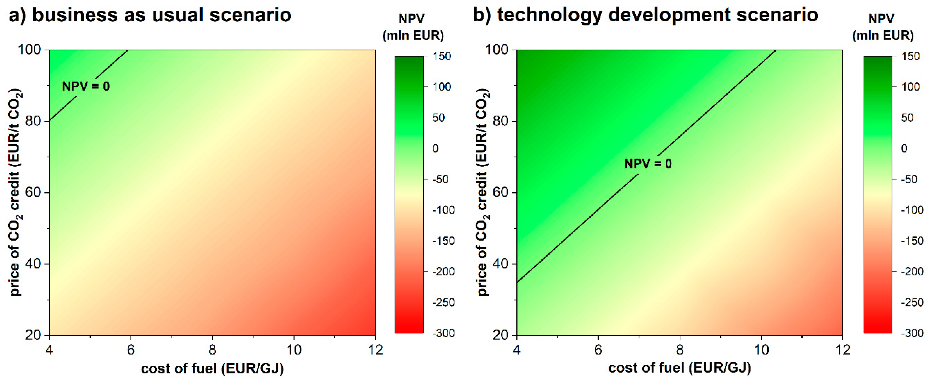
In
Figure 14, the NPV in the function of the cost of fuel and the price of negative CO
2 emission credit is presented for the business as usual and the technological development scenarios. It is clear that, with an increase of the price of biomass (fuel), a lower NPV can be obtained. On the other hand, the increase in the CO
2 credits helps to increase the profitability of the project. With a decrease in the costs of fuel to 4 EUR/GJ (which is a closer price range in, e.g., the USA) and the technological development of the system components (which is possible, taking into account, e.g., the decrease in the investment cost for other renewable energy source technologies and CO
2 capture technology itself), the BEP of the negative CO
2 emission credit is around 35 EUR/t CO
2, which is a very promising option for heat and electricity supply together with carbon dioxide removal from the atmosphere.
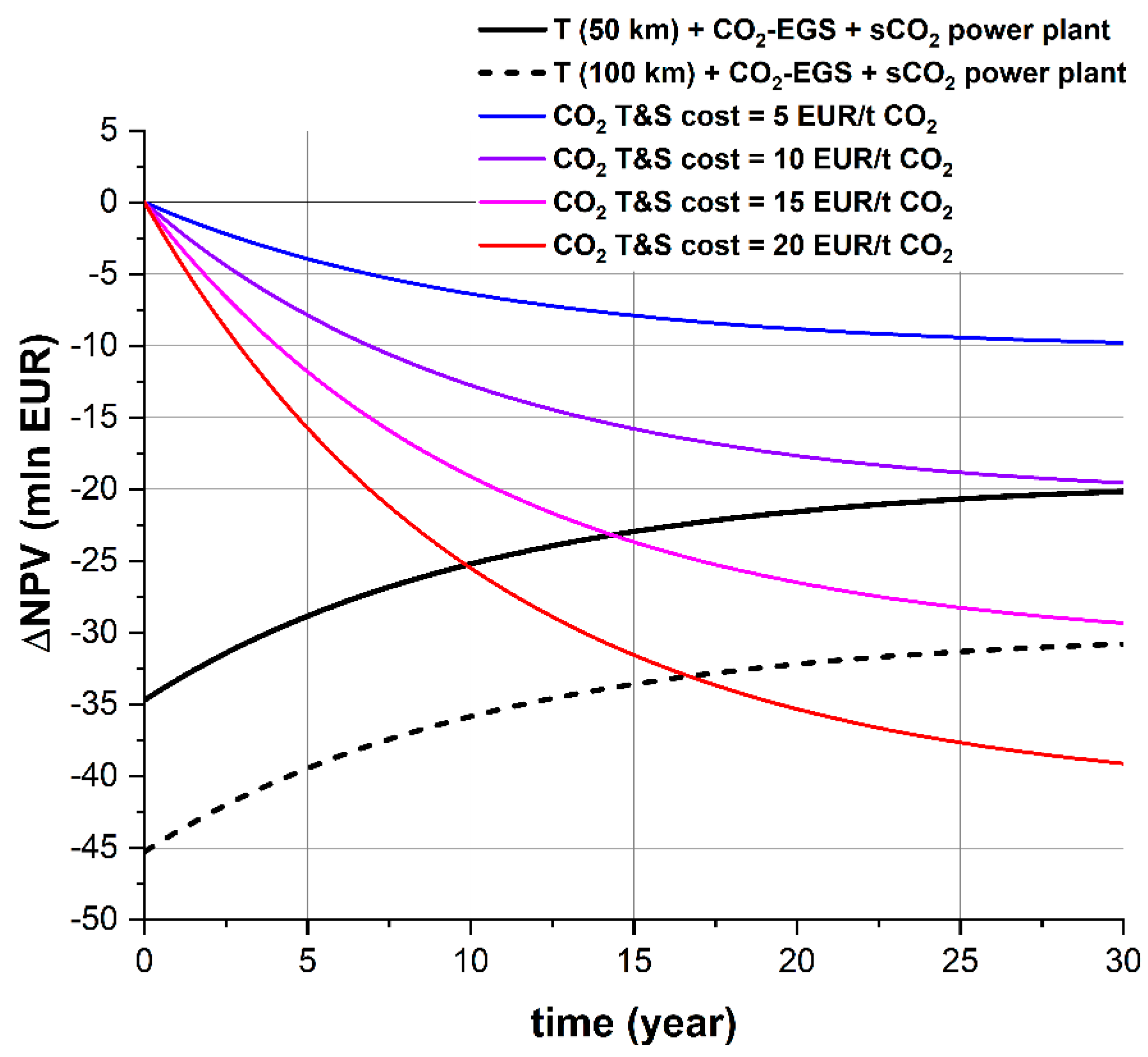
Within the analyzed system, the TSC includes the costs associated with CO2 utilization—the CO2 transport pipeline, CO2-EGS system development (drilling and fracturing), and the sCO2 power plant. This approach might not correspond to current trends in CCUS technologies, while dedicated operators are proposed for CO2 transport and CO2 utilization or storage.
In
Figure 15, the impact including the proposed CCUS chain associated with CO
2 transport and utilization on the NPV is presented. The black lines correspond to the currently analyzed option for two CO
2 transport distances (50 and 100 km). The coloured lines indicate the impact on the NPV when the costs of CO
2 transport and storage (T&S) are given. As can be seen, the proposed option (for a 50 km CO
2 transport pipeline) is competitive when the CO
2 transport and storage costs are above 10 EUR/t CO
2 (which is the case for Poland [
82]). This proves that the proposed design of CO
2 transport and utilization (including storage) is an economically favorable option, and that the electricity production from renewable energy sources (geothermal energy) can be increased.
3.3. Technology Readiness Level of the Analyzed Concept
The concept of the Technology Readiness Level (TRL) is used to estimate the maturity level of a technology, which is necessary to achieve a low-carbon economy but not yet available at a commercial scale. One of them is CCS, including BECCS. However, there are factors that can put important limitations on its global spread. These include a lower efficiency compared to other combustion methods and a weak infrastructure for CO
2 transport and storage. On the combustion side, a lower energy density and less ash deposition can be problematic [
86]. However, the key prerequisites for large-scale BECCS are the availability of biomass feedstock and land for production. The challenges for the former include competition between different sectors of the economy for feedstock and competition with other ecosystem services, for example food production. The seasonal availability of certain crops can also be a limitation. A related issue is land availability for biomass feedstock production. BECCS is one of the CCS technologies that have reached (or are close to reaching) the commercial phase of development. What is underlined by researchers is that BECCS’ spread relies on a mature CCS industry. In 2019, five BECCS plants were operating worldwide. By 2100, this could provide more than 5% of total global primary energy [
87]. However, if other negative emission technologies are to be quickly developed, this could potentially lead to a slower and lower uptake of BECCS. This can only be realized if they are to be cost-competitive in comparison to BECCS [
87].
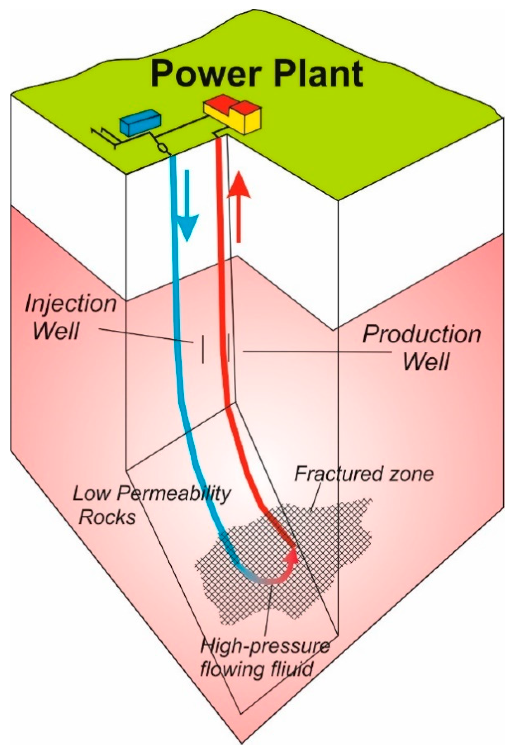
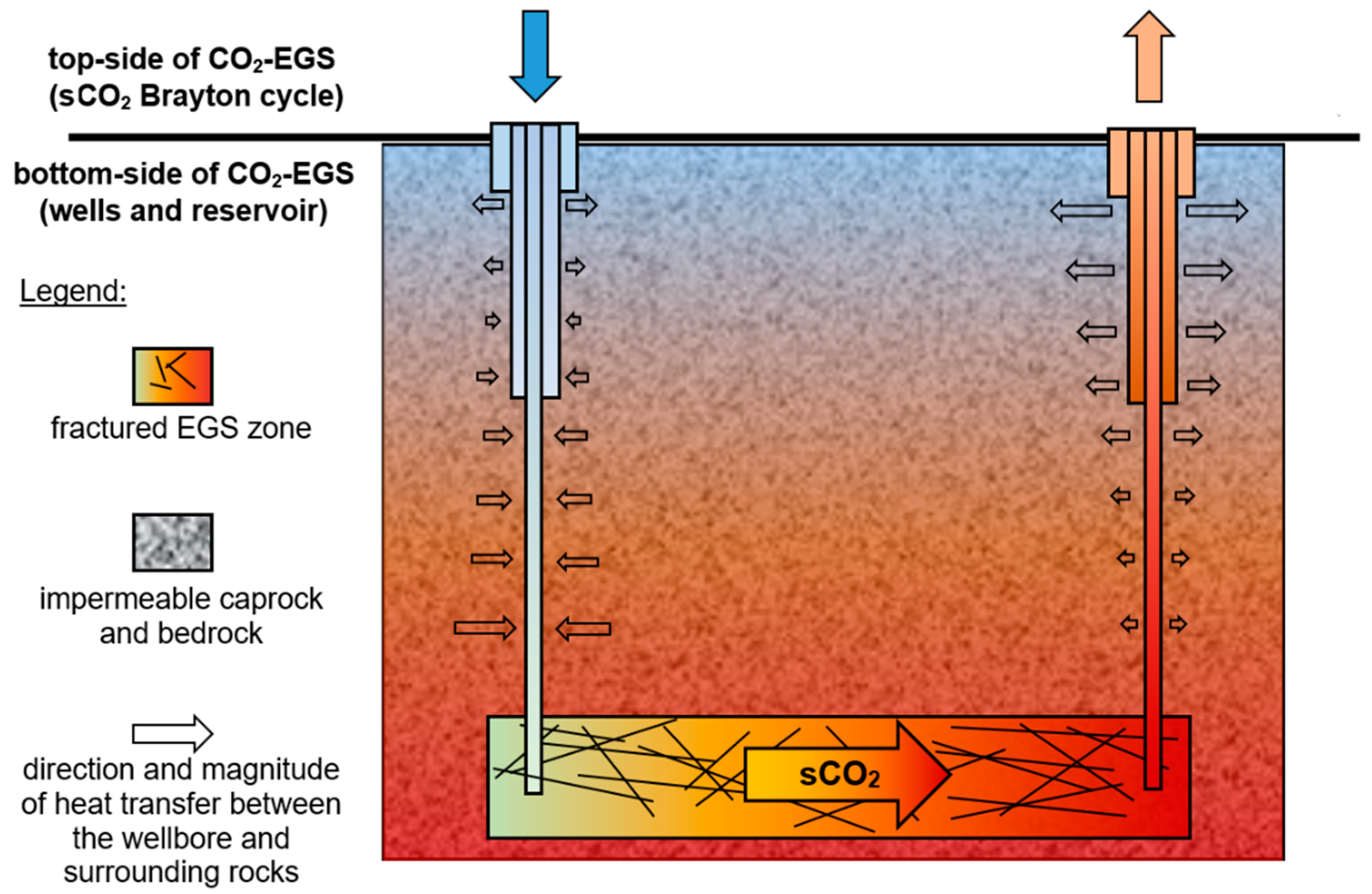
There were four EGS sites in the US in 2017, operating at around a 2 MW
el capacity. Some of them are planned to reach 5 MW
el by 2020. However, the small project size can be misleading, as
the target is the development of (low- and medium-temperature) geothermal systems in the range of hundreds of kWe to an MWe for electricity in remote towns as well as the utilization of coproduced thermal power generation that results from the by-products of existing oil and gas wells. Only afterwards is the development of larger systems planned [
42]. There have been attempts to develop an EGS in Asia as well. Japan developed two, but they are now closed. South Korea, China, and Taiwan are currently experimenting with the technology [
42,
88]. It has also been recently argued that, despite promising initial ideas on applying unconventional oil and gas technologies, there are shortcomings that make EGSs uneconomical [
89]. Research has indicated that an adequate mass flow rate, of 80 kg/s at 200 °C, is required for the proper functioning of an EGS plant. However, the systems currently in operation do not even reach 25 kg/s [
90]. Moreover, the costs of deep wells remain highly uncertain [
90]. The key challenge that remains addressed is how to establish and maintain a suitable reservoir. Furthermore, its change over time is insufficiently understood. Finally, knowledge on the long-term interaction between working fluids and rock structure is incomplete [
91]. To sum up, EGSs are heavily subsidized and are more expensive than other energy sources, which makes them not economically feasible. Therefore, governments should focus on reducing costs to 2030 to a competitive level [
88]. This is assuming remarks that refer to a water-based EGS, while the TRL level of a CO
2-based EGS is around 3–4.
There are five research institutes in the US and one each in Japan and South Korea that have indicated experimentation with sCO
2 since 2009 [
48,
92]. According to the energetic rule of thumb that thermal efficiency rises with the size of the system, sCO
2 efficiency is expected to rise. However, all test facilities operate at small scales; therefore, the development of a large-scale (>10 MW) prototype sCO
2 system is necessary [
92], and some of the most recent research points out that scaling up remains an issue [
47,
48]. Better designs of heat exchangers, bearings, and seals are necessary [
47]. Two experiments of the application of the sCO
2 power cycle in geothermal energy have shown that (1) the relationship between the mass flow rate of sCO
2 and the power capacity is nonlinear and that (2) the cycle efficiency was around 18% [
47]. Thus, the overall TRL is also rather low, around 4–5.
Thus, taking into account all of the aforementioned considerations, the overall TRL of the proposed concept can be assessed as TRL4 (technological development), mainly due to the early stage of the CO2-enhanced geothermal system development.


