Fabrication of Mn-N-C Catalyst for Oxygen Reduction Reactions Using Mn-Embedded Carbon Nanofiber

1
Departments of Chemical Engineering, College of Engineering, Wonkwang University, Iksan, Jeonbuk 54538, Korea
2
Nanoscale Sciences and Technology Institute, Wonkwang University, Iksan, Jeonbuk 54538, Korea
*
Author to whom correspondence should be addressed.
Energies 2020, 13(10), 2561; https://doi.org/10.3390/en13102561
Submission received: 28 March 2020
/
Revised: 12 May 2020
/
Accepted: 14 May 2020
/
Published: 18 May 2020
(This article belongs to the Special Issue Application of Composite Materials for Energy Devices)
Abstract
:The development of efficient and cost-effective electrocatalysts for oxygen reduction reactions (ORR) is one of the most crucial goals in the field of energy conversion devices such as fuel cells or metal-air batteries. Until now, the platinum-based catalyst has been considered the gold standard electrocatalyst and is widely used for ORR. In recent times, transition metal-nitrogen (N)-carbon (C)-based electrocatalysts have verified ORR performances comparable to novel metal-based catalysts. However, due to the complex production methods and low yield, their high price is their one major disadvantage compared to platinum-based catalysts. Herein, we present a transition metal-N-C electrochemical catalyst prepared by simple electrospinning and heat treatment. The metal- and nitrogen-embedded carbon nanofiber represents considerably enhanced activity for oxygen reduction reactions compared to pristine carbon nanofiber.
1. Introduction
Fuel cells, supercapacitors and metal-air batteries are front runners in the race to find the next generation of energy sources that will power various electronic products, from large electronic devices such as electric vehicles, to small electronic devices such as wearable electronics. For these energy sources to become ubiquitous, fuel cells, supercapacitors and metal-air batteries all need oxygen reduction reaction (ORR) catalysts that have superior performance and cost competitiveness compared to what is available now [1,2,3,4,5,6,7,8,9,10,11,12,13,14,15,16,17,18]. Despite the fact that precious metals such as Pt and Pt-based alloys have been considered superior electrocatalysts for ORR over the last few decades [6,7], many research groups have been focusing on developing precious metal-free catalysts because of the high expense and restricted amounts of precious metal catalysts [8,9,10,11,12,13,14,15,16,17,18].
Carbon materials have been widely used in diverse areas, especially in energy devices, due to their high electrical conductivity, large surface area, chemical stability and low density. Recently, heteroatom-embedded carbon materials such as carbon, [8,9,10,11] carbon nanotubes [12,13,14], graphene [15,16] and graphene nanoplates [17] have been regarded as alternatives to Pt-based catalysts because of their superior catalytic performance in ORRs. Among the various carbon materials, carbon nanofiber (CNF) prepared by electrospinning has exhibited higher electrical conductivity and a larger specific surface area than commercial carbon particles. The high electrical conductivity of CNF originates from minimized resistance due to electrons moving smoothly along the axis in the direction of the uniformly arranged fibers. In addition, nonwoven CNF can be used directly as a self-standing electrode without any additional binder materials. Electrospinning is a unique method that can manufacture nonwoven nanofiber using electrostatic repulsion and an electric field between two electrodes (syringe and collector) that supply high voltage to a polymer-based solution [17,18,19,20,21]. Polyacrylonitrile (PAN) is one of the raw materials used for preparing CNF via electrospinning. The nonwoven web obtained from electrospinning is produced in the form of a carbon nanofiber web through stabilization and carbonization. As PAN has a nitrogen atom in its polymer chain, several research groups have prepared the N-doped CNF with PAN nanofiber and investigated its catalytic properties for ORR [21]. However, the N-doped CNF exhibited insufficient catalytic properties which may be related to the amount of nitrogen in the CNF. During stabilization and carbonization, some nitrogen atoms may have been embedded in the carbon lattice, however almost all nitrogen was removed from the PAN molecules during production.
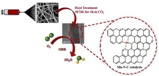
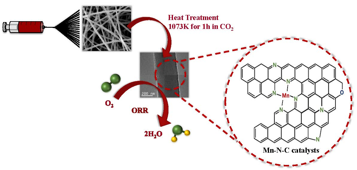
In this study, we prepared Mn-N-C catalysts by electrospinning a solution and added a small amount of manganese ions to the PAN solution. The Mn-N-C structure or MnO-embedded carbon nanofibers were fabricated by controlling the amount of manganese added. The carbon nanofibers with an Mn-N-C structure exhibited stable catalytic properties.
2. Materials and Methods
Manganese nitrate-embedded Polyacrylonitrile (PAN, Sigma Aldrich Co.) fibers were fabricated by electrospinning the polymer solution, which consisted of the desired amount of manganese acetate and 10 wt.% PAN polymers dissolved in N,N-dimethylformamide (DMF, Samchun Pure Chemical Co., Ltd.). The amount of manganese acetate ((CHCO2)2Mn·4H2O, Sigma Aldrich Co.) was adjusted by calculating the number of manganese ions to give 10 at.% and 40 at.% of the nitrogen contained in the PAN monomer. The composite solution was electrospun in the form of a fiber web through a positively charged capillary tip of 0.5 mm in diameter using a power supply (Conver Tech., Korea). The electrospun fibers were collected as a web on a metal collector rotating at approximately 300 rpm. For electrospinning, the supplied voltage was 18 kV, the distance from the syringe needle tip to collector was 18 cm and the flow velocity of the solution was 1 mL/h. Electrospun fibers were stabilized by heating to 553 K at a rate of 1 K/min in air and then kept at 553 K for 1 h. The stabilized fibers were carbonized by heating to 1073 K for 1h in CO2. The CNFs were designated as CN, CN-Mn1 and CN-Mn2 as a function of the amount of Mn precursor contained.
Morphological observations of the electrospun and manganese-embedded carbon nanofibers were conducted by scanning electron microscopy (FE-SEM, Hitachi, S-4800, Japan). The weight loss of the electrospun PAN fibers was estimated by thermogravimetric analysis (TGA, PerkinElmer, TGA8000, USA). The specific surface areas and pore size distributions were evaluated using the Brunauer–Emmett–Teller (BET) equation (BELSORP-mini II, Mictrotrac-BEL, USA). The X-ray diffraction (XRD) pattern was conducted with a MiniFlex (Rigaku, Japan). Transmission electron microscope (TEM) observation was performed with a JEM-2100 (JEOL, USA).
Rotating disk electrode (RDE) tests were carried out using an electrochemical workstation and computer-controlled potentiostat (SP-300) between −0.8 V and 0.2 V at a scan rate of 50 mV/s in 0.1 M KOH solution as electrolyte. A platinum wire was used as a counter electrode and an Hg/HgO (1 M NaOH) electrode was used as the reference electrode. The working electrodes were fabricated by applying each of the catalyst inks onto a prepolished glassy carbon (GC) disk electrode (5 mm in diameter). The electrocatalyst (15 mg) was dispersed in ethanol (1.0 mL) and ultrasonicated for 30 min. A total of 5 μL of catalyst ink was applied onto the working electrode and dried at room temperature for 15 min before electrochemical tests. The loading of the catalysts for all the measurements was maintained at 0.382 mg/cm2. Linear sweep voltammetry (LSV) data values measured using an Hg/HgO (1 M NaOH) reference electrode were converted to LSV data values at the reversible hydrogen electrode (RHE) reference electrode using a calculation formula (ERHE = EHg/HgO + 0.059 pH + E°Hg/HgO). Cyclic voltammograms were carried out using a BCS-815 electrochemical workstation using a 6 M KOH as electrolyte at potential ranging from 0 to 0.9 V and scan rate of 2 mV/s. The electrode was prepared by mixing 80 wt.% of electrode active material, 10 wt.% of the polyvinylidene fluoride (PVDF, mol weight (MW) ≈ 534,000 g·mol−1, Sigma Aldrich Co) as binder, 10 wt.% of Super-P as conductive carbon material and N-methyl-2-pyrrolidone as the solvent for preparing a slurry. The slurry was pressed onto the nickel foam and dried at 373 K in a vacuum oven for 1 h. The electrochemical cells were prepared with the electrode materials on nickel foam as current collector and polypropylene separator (Cellgard 3501, Scimat Co., UK).
3. Results
Characterization
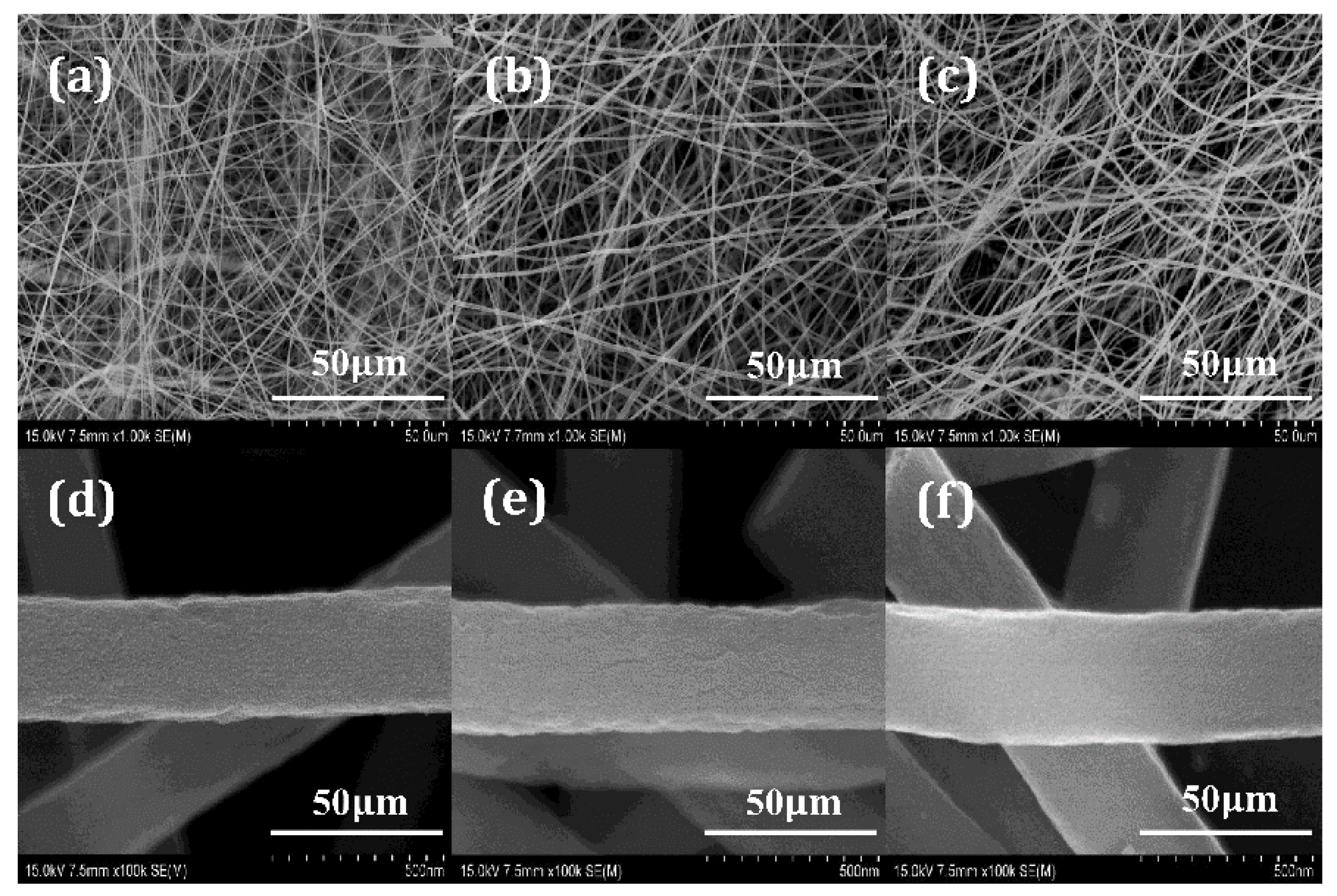
Figure 1a–c shows SEM images of the electrospun PAN nanofiber and Mn-embedded PAN nanofiber web. The PAN-based fibers were partially aligned along the winding direction of the drum collector and the diameters of the fibers were distributed in a range of 400 to 1000 nm with an average diameter of 593 nm (Figure 1a). The Mn-embedded nanofibers had a rougher surface, showing a more bent and wrinkled appearance with increasing Mn content, as shown in Figure 1b,c. The reason the nanofiber morphology became more inconsistent and wrinkled as the content of manganese precursor increased may be related to an associated change in the conductivity of the solution used for electrospinning [22]. Figure 1d–f shows SEM images of the carbon nanofibers with different Mn contents. The carbon nanofiber without Mn precursor showed a slightly rough surface and a decreased average diameter of 450 nm with a range of 200 to 600 nm (Figure 1d). The Mn-embedded carbon nanofibers’ surfaces became rougher and their average diameter reduced to 480 nm (diameter range = 150–600 nm) with increasing Mn content. Furthermore, the CN-Mn2 showed a polycrystalline structure as well as a decrease in diameter. This reduction in fiber diameter originated from the incremental change in electrical conductivity of the spinning solution from adding the manganese precursor [23]. The addition of a metal precursor such as manganese acetate was made to lower the viscosity of the spinning solution and increase the amount of charge carriers. Accordingly, enhanced conductivity of the solution was achieved, the diameter of the fiber fabricated by electrospinning was decreased [24].
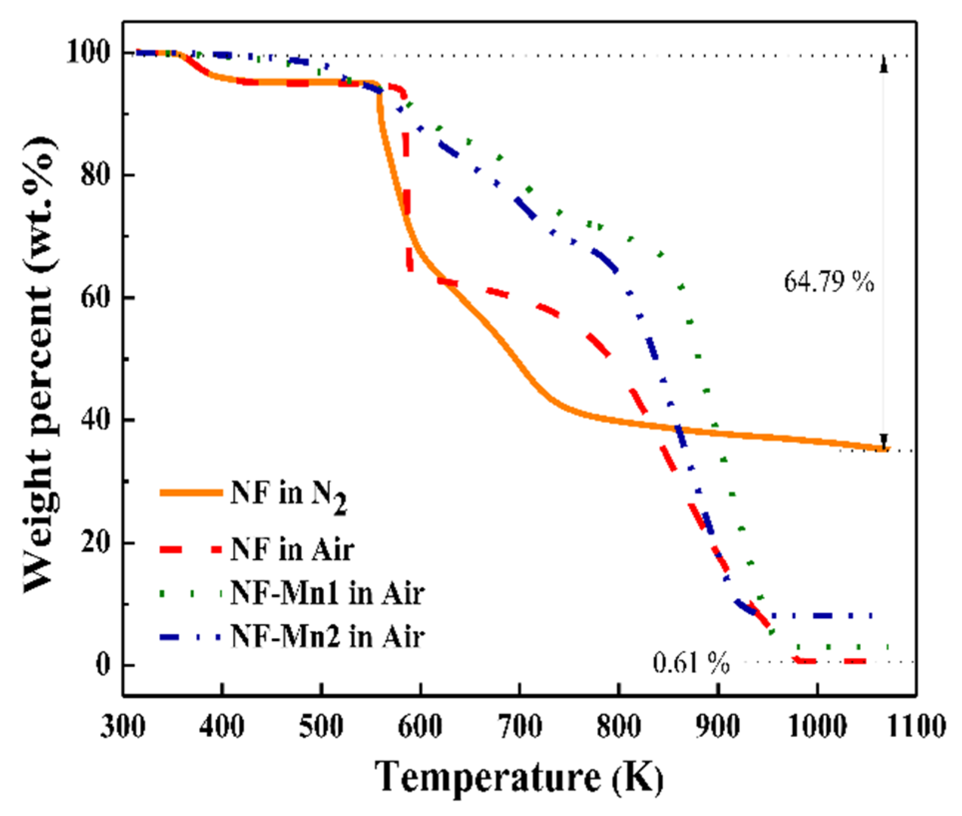
Figure 2 shows the TGA results of the electrospun PAN-based fibers in a nitrogen and air atmosphere. The content of manganese oxide embedded in the carbon nanofibers was estimated from the residual amount of the electrospun PAN composite fibers after burning in air. The PAN fibers in the air nearly completely decomposed due to the activity of the oxygen, while the PAN fibers in nitrogen decomposed to 64.79 wt.%, representing a carbonization yield of 35.21 wt.%. The residual content of the Mn-free nanofibers was 0.61 wt.%, which exhibited the amount of fibers remaining after combusting the PAN fiber in air. The remnant contents of CN-Mn1 and CN-Mn2 were 2.29 and 4.84 wt.%, respectively. The manganese content was decided by subtracting the remnant carbon nanofibers from the remnant contents of the Mn-carbon nanofibers.
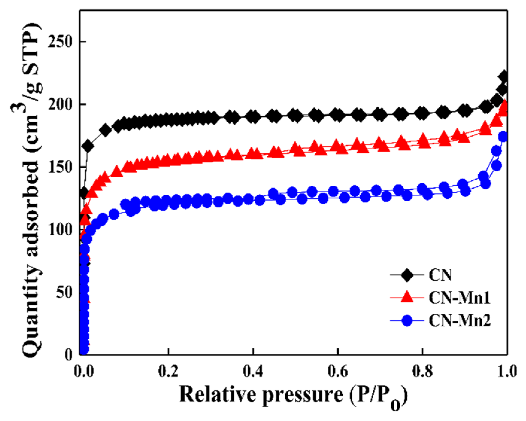
Figure 3 represents the nitrogen adsorption isotherms of the CN, CN-Mn1 and CN-Mn2 as a function of relative pressure. The isotherm of the MnO-free CN sample exhibited micropore adsorption but without using mesopores so can be described as a typical type I. This means that the CN sample hardly involved any mesopores. On the other hand, the isotherms of CN-Mn1 and CN-Mn2 exhibited both micropore and mesopore adsorption with a narrow size distribution so could be described as a typical type IV, and these samples also showed hysteresis curves. The hysteresis phenomenon of Mn-CN1 started to appear at a relative pressure P/Po = 0.47, while that of Mn-CN2 started to occur at a relative pressure P/Po = 0.43, and showed a larger hysteresis curve. This means that the mesopores became more developed in the process of carbonization as the amount of manganese precursor increased. The specific surface areas of the CN, CN-Mn1 and CN-Mn2 were 777 m2/g, 534 m2/g and 448 m2/g, respectively. The small specific surface area of the CN-Mn samples was due to the higher proportion of heterogeneous elements that partially blocked the micropores and so had less influence on the specific surface area [25].
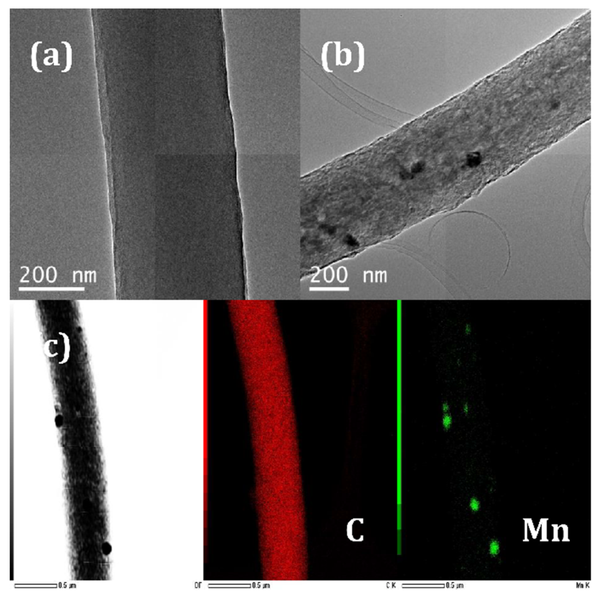
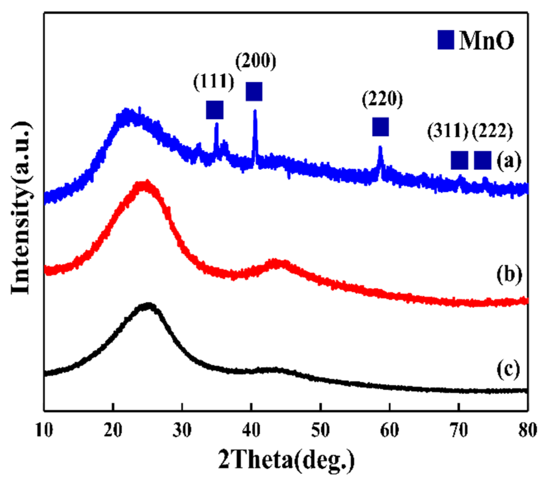
To confirm what form the manganese precursors took in the carbon fiber, TEM and XRD analyses were performed. Figure 4 shows the TEM images of CN-Mn1 and CN-Mn2. The CN-Mn1 as shown in Figure 4a exhibited a straight appearance with a smooth surface of carbon fibers without any crystallized particles. However, Figure 4b shows some particles that are dispersed below 20 nm in CN-Mn2. EDX analysis was performed on the particles identified in the TEM, these particles were composed of Mn and oxygen, as shown in Figure 4c. Figure 5 shows the XRD patterns of carbon nanofibers. The CN displayed two broad diffraction peaks at 2θ = 24 and 43°, indicating a typical microcrystalline carbon structure. In addition, CN-Mn1 also showed a typical carbon structure without any manganese-related diffraction peaks. On the other hand, CN-Mn2 showed several MnO peaks which were at 2θ = 19 (111), 37 (311) and 45° (400). The low intensities of MnO allowed the MnO particles to be located inside as well as on the surface of the carbon fiber, as can be seen in the TEM images.
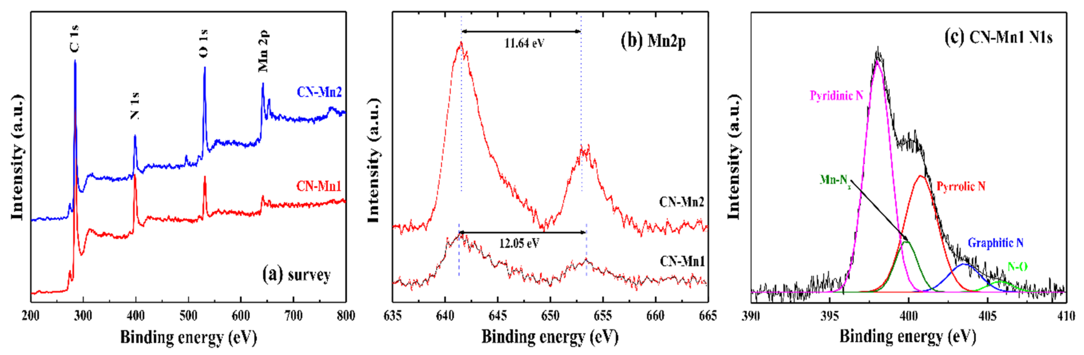
To confirm the chemical bonding states and chemical compositions of the CN-Mn samples, X-ray photoelectron spectra (XPS) analysis was performed with the MultiLab 2000 XPS system (Thermo Scientific, USA). The XPS survey spectrum (Figure 6a) showed C 1s, N 1s, O 1s and Mn 2p in the CN-Mn1 and CN-Mn2 samples. The atomic ratios of manganese to nitrogen were 11.88% and 57.77% for CN-Mn1 and CN-Mn2, respectively. The actual manganese content was slightly higher than the value calculated using the nitrogen atoms included in the PAN monomer due to some nitrogen being removed during the heat treatment. The atomic percent of oxygen in CN-Mn2 (15.27 at.%) was significantly higher than in CN-Mn1 (6.07 at.%). This was related to the formation of a MnO crystal structure in CN-Mn2 as shown in the XRD and TEM results. The Mn 2p1/2 (654 eV) and Mn 2p3/2 (641 eV) peaks were confirmed by high resolution XPS spectra of Mn 2P, as shown in Figure 6b. The energy separation between 2p1/2 and 2p3/2 of CN-Mn2 was 11.64 eV, which indicated an Mn(II) oxidation state [26]. On the other hand, CN-Mn1 exhibited a higher energy gap between 2p1/2 and 2p3/2 of 12.05 eV. The difference in oxygen states indicated a change in the oxidation state of Mn ions in the CN-Mn samples. Figure 6c shows the N 1s spectrum in CN-Mn1 fitted with five peaks, including oxidized nitrogen, graphitic nitrogen, pyrrolic nitrogen, Mn-nitrogen compounds and pyridinic nitrogen. The percentage of each pyridinic N, Mn-Nx, pyrrolic N, graphitic N and N-O species was 49.42%, 9.28%, 31.79%, 7.31% and 2.20%, respectively. With this XPS analysis, it was confirmed that manganese formed the manganese-nitrogen compounds in CN-Mn1. Enhanced catalytic properties could be expected after adding manganese precursor to the carbon nanofiber because pyrrolic nitrogen, metal-nitrogen and pyridinic nitrogen are known to significantly improve the oxygen reduction reaction [15].
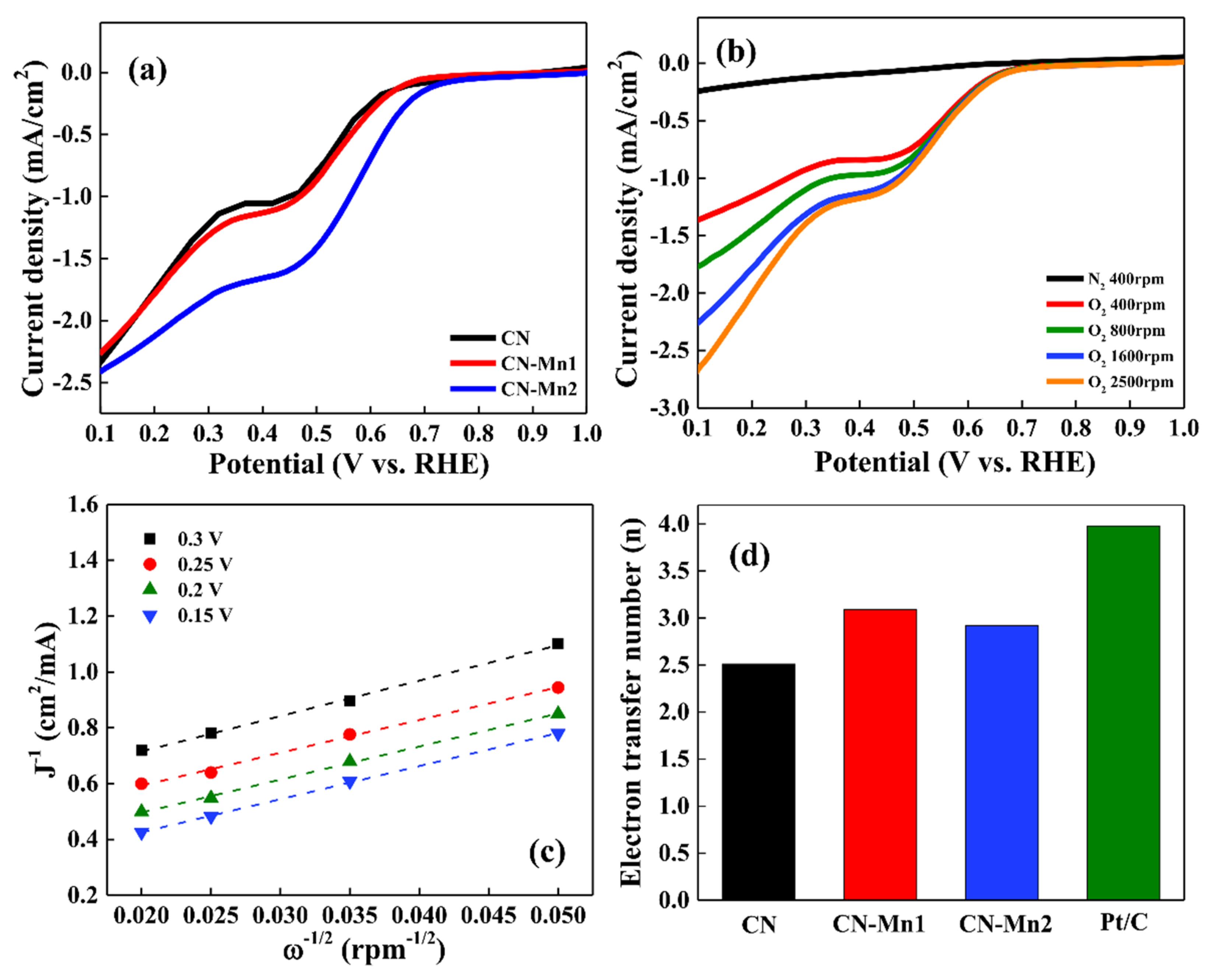
Figure 7 shows the ORR activities of CN-Mn samples prepared with different contents of manganese precursor. Figure 7a shows the catalytic properties of different catalysts at 200 cycles. Liu et al. reported that the sample with a high specific surface area had increased current density in the ORR reaction [27]. Likewise, the CN catalyst with a high specific surface area exhibited high current density compared with the other samples. However, the CN catalyst had a relatively small onset potential (0.62 V) and the onset potential increased to 0.65 V (CN-Mn1) and 0.70 V (CN-Mn2) by increasing the manganese amount. The onset potential of the CN-Mn catalysts showed a lower value compared to the onset potential (0.96 V vs. RHE) of commercial Pt/C reported in other papers [28]. In addition, metal-nitrogen-carbon catalysts using other transition metals, such as iron or cobalt, showed superior onset potential of 0.81 V [29] and 0.87 V [30], respectively. Huang et al. reported that ORR activity of a metal-N-C catalyst can be significantly changed depending on the transition metal and the ORR activity of the catalyst, following the order of Fe > Co > Zn > Mn [31]. Therefore, the reason why the CN-Mn samples showed low onset potential compared to the previously reported M-N-C catalysts was thought to be due to the low catalytic properties of Mn. The RDE polarization curve of CN-Mn1 is shown in Figure 7b at different rotation rates from 400 rpm to 2500 rpm. As the rotation rate increased, the current density increased due to the rapid oxygen flux to the electrode surface. The RDE polarization curves at different rotation rates were used to construct the K-L plot shown in Figure 7c, where the electron transfers number (n) was calculated and shown in Figure 7d. The electron transfer numbers of the CN-Mn1 and CN-Mn2 calculated through the K-L equation were 3.09 and 2.92, respectively. Compared to the commercial platinum catalyst (Pt/C, n = 3.98), CN-Mn samples had a low electron transfer number because very few Mn-N-C sites formed. However, compared with the Mn free-CN sample (n = 2.51), the improved electron transfer number showed that the formation of the Mn-N-C site played an important role in oxygen reduction reaction catalysis.
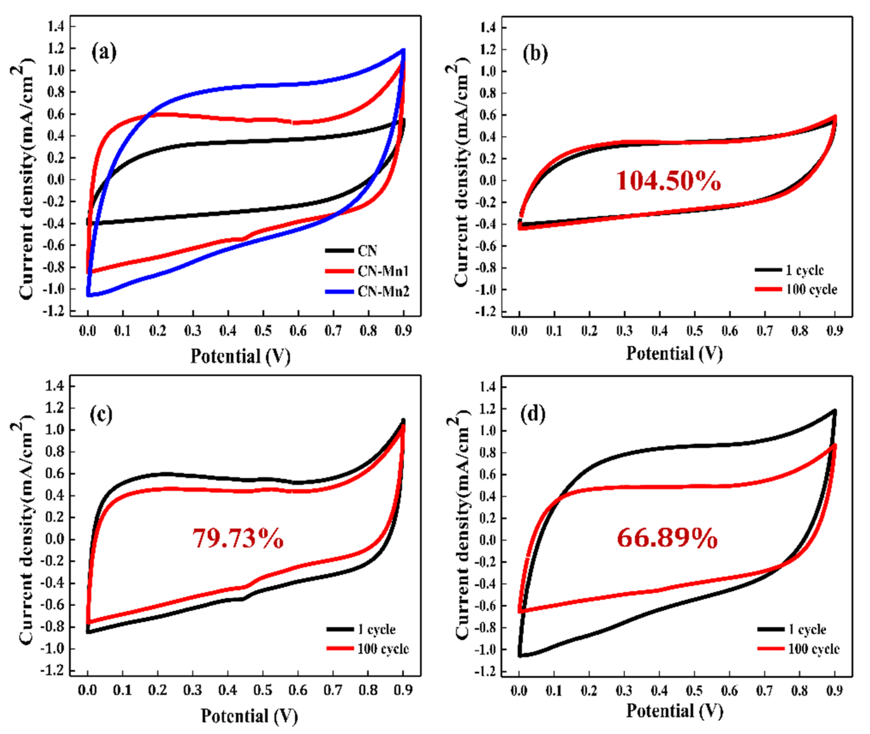
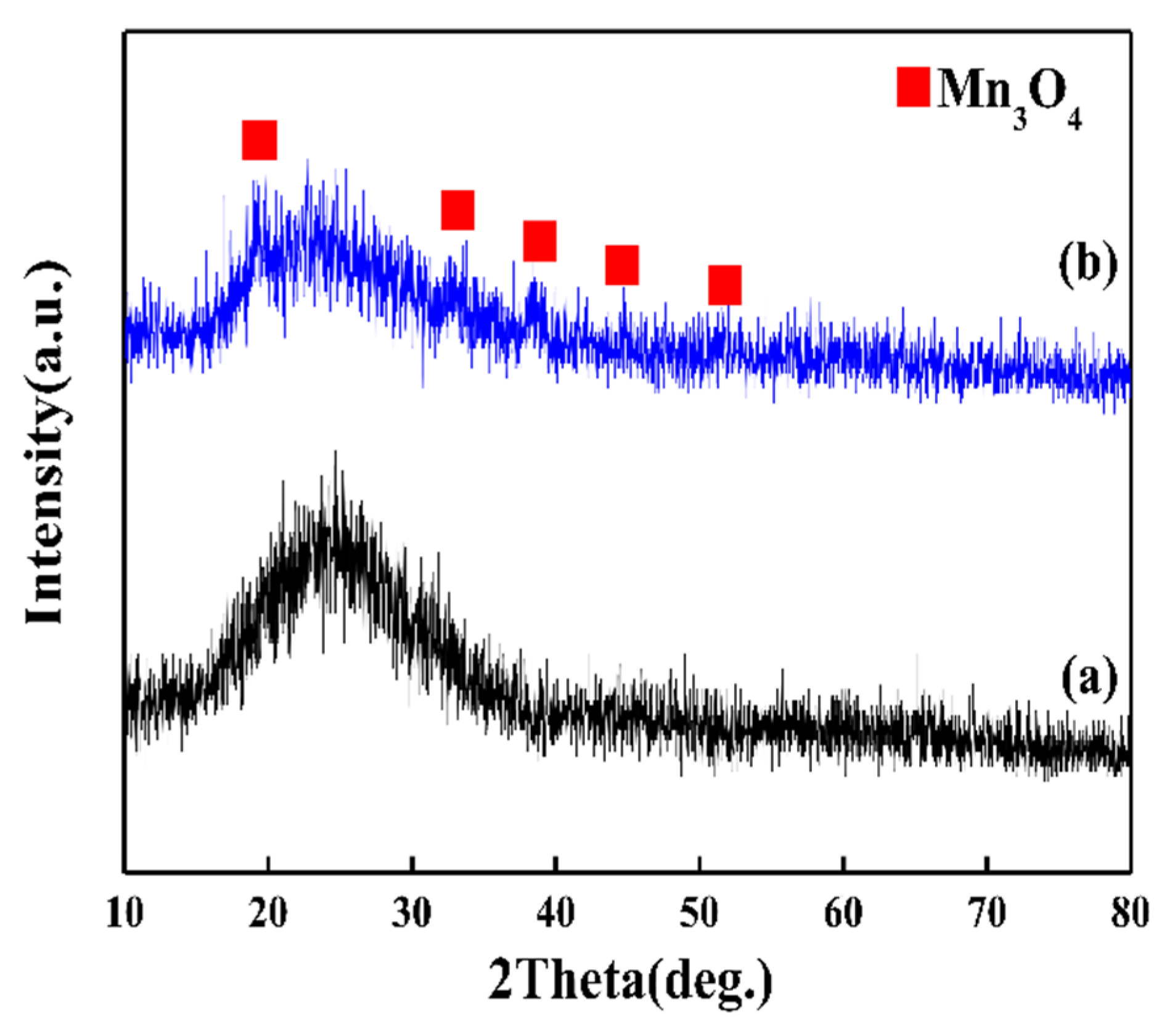
Cyclic voltammetry (CV) tests were conducted to evaluate the electrochemical properties of the CN-Mn electrode in a supercapacitor. The electrode was prepared on an Ni form current collector without any additives such as binders or conductive material. The CV test was performed with a potential ranging from 0 to 0.9 V in 6 M KOH electrolyte. All CV curves represented a near-rectangular shape without any evident redox peaks and the leveled current density increased as the amount of manganese precursor increased (Figure 8a). In general, the leveled current density of CV was related to the surface area of the electrode in the supercapacitor when there were critical redox peaks. As shown in the results of the BET analysis, the surface area of the CN-Mn samples was decreased by increasing the amount of Mn additive. The reason why the CN electrode showed such small CV curves despite its large specific surface area was that the CN sample had well developed micropores. In contrast, the CN-Mn samples showed large CV curves in spite of a small specific surface area due to the well-developed mesopores of the CN-Mn [32] and from a synergy effect in the catalytic activity of Mn-N-C or MnO. The specific capacitances calculated from the CV curves of CN, CN-Mn1 and CN-Mn2 were 136, 261 and 315 F/g, respectively. The durability of the CN-Mn electrode during long-term cycling has also been confirmed, as shown in Figure 8b–d. After the 100th cycle, the specific capacitance of the CN electrode had slightly increased to 142 F/g, in contrast, the CN-Mn1 and CN-Mn2 electrodes exhibited reduced specific capacitances of 208 and 211 F/g, respectively. The enhanced specific capacitance of the CN electrode originates from the full activation of the electrode due to increasing the effective interfacial area between the CN electrode and the electrolyte [33]. The capacitance in CN-Mn1 and CN-Mn2 samples could be related to the removal of oxygen groups in carbon [34] or the instability of the electrode potential by the dissolution of the electrode active material in the electrolyte and capacity imbalances between the electrodes [35]. Therefore, to confirm the cause of capacity degradation, XRD analysis was performed with the electrode materials after the durability tests on the supercapacitor, as shown in Figure 9. The XRD measurement results showed that the intensity of the XRD peak of both samples was reduced after the electrochemical experiment, and that significant changes had not occurred in the CN-Mn1 sample during the cycle test. However, it was confirmed that Mn3O4 peaks instead of the peaks representing the crystal structure of MnO were produced in the CN-Mn2 sample during cycling testing. Based on the ORR and XRD analysis results, we can conclude that the reduction of the CV curve of CN-Mn1 is interrelated to the removal of oxygen functional groups on the carbon surface, and the reduction in the capacity of CN-Mn2 originates from structural changes caused by the dissolution of manganese from MnO.
4. Conclusions
Manganese-embedded carbon composite nanofibers were synthesized by a procedure of stabilization and activation after the use of an electrospinning technique. Manganese in the carbon fiber formed Mn-N-C or MnO depending on the amount of manganese precursor used. The electrocatalytic performance of the MnO significantly decreased during durability testing due to changes in the crystal structure of manganese oxide. On the other hand, the Mn-N-C catalyst showed stable catalytic properties. In an electrode test of a supercapacitor, the specific capacitance of the carbon nanofibers without manganese was 142 F/g, whereas the specific capacitance of the carbon nanofibers containing Mn-N-C compounds was 208 F/g.
Author Contributions
Author Contributions: Conceptualization, H.-Y.K. and Y.-W.J.; methodology, Y.-W.J.; validation, H.-Y.K. and Y.-W.J.; formal analysis, H.-Y.K.; investigation, H.-Y.K. and Y.-W.J.; resources, Y.-W.J.; data curation, H.-Y.K. and Y.-W.J.; writing—original draft preparation, H.-Y.K.; writing—review and editing, Y.-W.J.; visualization, H.-Y.K.; supervision, Y.-W.J.; project administration, Y.-W.J.; funding acquisition, Y.-W.J. All authors have read and agreed to the published version of the manuscript.
Funding
This research was funded by Wonkwang University in 2018.
Conflicts of Interest
The authors declare no conflict of interest.
References
- Wu, G.; More, K.L.; Johnston, C.M.; Zelenay, P. High-Performance Electrocatalysts for Oxygen Reduction Derived from Polyaniline, Iron, and Cobalt. Science 2011, 332, 443–447. [Google Scholar] [CrossRef] [Green Version]
- Proietti, E.; Jaouen, F.; Lefèvre, M.; Larouche, N.; Tian, J.; Herranz, J.; Dodelet, J.-P. Iron-based cathode catalyst with enhanced power density in polymer electrolyte membrane fuel cells. Nat. Commun. 2011, 2, 416. [Google Scholar] [CrossRef] [PubMed]
- Yuan, C.; Wu, B.H.; Xie, Y.; Lou, X.W. Mixed transition-metal oxides: Design, synthesis, and energy-related applications. Angew. Chem. Int. Ed. 2014, 53, 1488–1504. [Google Scholar] [CrossRef] [PubMed]
- Jiao, Y.; Zheng, Y.; Jaroniec, M.; Qiao, S. Design of electrocatalysts for oxygen- and hydrogen-involving energy conversion reactions. Chem. Soc. Rev. 2015, 44, 2060–2086. [Google Scholar] [CrossRef] [PubMed]
- Fu, S.; Zhu, C.; Song, J.; Du, D.; Lin, Y. Metal-Organic Framework-Derived Non-Precious Metal Nanocatalysts for Oxygen Reduction Reaction. Adv. Energy Mater. 2017, 7, 1700363. [Google Scholar] [CrossRef]
- Lim, B.; Jiang, M.; Camargo, P.H.C.; Cho, E.C.; Tao, J.; Lu, X.; Zhu, Y.; Xia, Y. Pd-Pt Bimetallic Nanodendrites with High Activity for Oxygen Reduction. Science 2009, 324, 1302–1305. [Google Scholar] [CrossRef] [Green Version]
- Peng, Z.; Yang, H. Designer platinum nanoparticles: Control of shape, composition in alloy, nanostructure and electrocatalytic property. Nano Today 2009, 4, 143–164. [Google Scholar] [CrossRef]
- Yang, L.; Zeng, X.; Wang, W.; Cao, D. Recent Progress in MOF-Derived, Heteroatom-Doped Porous Carbons as Highly Efficient Electrocatalysts for Oxygen Reduction Reaction in Fuel Cells. Adv. Funct. Mater. 2018, 28, 1704537. [Google Scholar] [CrossRef]
- Mahmood, J.; Li, F.; Kim, C.; Choi, H.-J.; Gwon, O.; Jung, S.-M.; Seo, J.-M.; Cho, S.-J.; Ju, Y.-W.; Jeong, H.Y.; et al. Fe@C2N: A highly-efficient indirect-contact oxygen reduction catalyst. Nano Energy 2018, 44, 304–310. [Google Scholar] [CrossRef]
- Ng, W.; Yang, Y.; Van Der Veen, K.; Rothenberg, G.; Yan, N. Enhancing the performance of 3D porous N-doped carbon in oxygen reduction reaction and supercapacitor via boosting the meso-macropore interconnectivity using the “exsolved” dual-template. Carbon 2018, 129, 293–300. [Google Scholar] [CrossRef]
- Guo, J.; Gadipelli, S.; Yang, Y.; Li, Z.; Lu, Y.; Brett, D.J.L.; Guo, Z.X. An efficient carbon-based ORR catalyst from low-temperature etching of ZIF-67 with ultra-small cobalt nanoparticles and high yield. J. Mater. Chem. A 2019, 7, 3544–3551. [Google Scholar] [CrossRef] [Green Version]
- Gong, K.; Du, F.; Xia, Z.; Durstock, M.; Dai, L. Nitrogen-Doped Carbon Nanotube Arrays with High Electrocatalytic Activity for Oxygen Reduction. Science 2009, 323, 760–764. [Google Scholar] [CrossRef] [PubMed] [Green Version]
- Yang, L.; Jiang, S.; Zhao, Y.; Zhu, L.; Chen, S.; Wang, X.; Wu, Q.; Ma, J.; Ma, Y.-W.; Hu, Z. Boron-Doped Carbon Nanotubes as Metal-Free Electrocatalysts for the Oxygen Reduction Reaction. Angew. Chem. Int. Ed. 2011, 50, 7132–7135. [Google Scholar] [CrossRef] [PubMed]
- Li, J.-C.; Zhao, S.; Tang, D.; Hou, P.-X.; Liu, C.; Cheng, H.-M.; Zhang, F. A 3D bi-functional porous N-doped carbon microtube sponge electrocatalyst for oxygen reduction and oxygen evolution reactions. Energy Environ. Sci. 2016, 9, 3079–3084. [Google Scholar] [CrossRef]
- Peng, H.; Mo, Z.; Liao, S.; Liang, H.; Yang, L.; Luo, F.; Song, H.; Zhong, Y.; Zhang, B. High Performance Fe- and N-Doped Carbon Catalyst with Graphene Structure for Oxygen Reduction. Sci. Rep. 2013, 3, 1765–1771. [Google Scholar] [CrossRef] [Green Version]
- Kamiya, K.; Hashimoto, K.; Nakanishi, S. Instantaneous one-pot synthesis of Fe–N-modified graphene as an efficient electrocatalyst for the oxygen reduction reaction in acidic solutions. Chem. Commun. 2012, 48, 10213. [Google Scholar] [CrossRef]
- Ju, Y.; Yoo, S.; Kim, C.; Kim, S.; Jeon, I.; Shin, J.; Baek, J.-B.; Kim, G. Fe@N-Graphene Nanoplatelet-Embedded Carbon Nanofibers as Efficient Electrocatalysts for Oxygen Reduction Reaction. Adv. Sci. 2015, 3, 1500205. [Google Scholar] [CrossRef]
- Guo, Q.; Zhao, D.; Liu, S.; Chen, S.; Hanif, M.; Hou, H. Free-standing nitrogen-doped carbon nanotubes at electrospun carbon nanofibers composite as an efficient electrocatalyst for oxygen reduction. Electrochim. Acta 2014, 138, 318–324. [Google Scholar] [CrossRef]
- Jiang, Y.; Zhang, J.; Qin, Y.-H.; Niu, D.-F.; Zhang, X.; Niu, L.; Zhou, X.-G.; Lu, T.-H.; Yuan, W.-K. Ultrasonic synthesis of nitrogen-doped carbon nanofibers as platinum catalyst support for oxygen reduction. J. Power Sources 2011, 196, 9356–9360. [Google Scholar] [CrossRef]
- Ren, G.; Lu, X.; Li, Y.; Zhu, Y.; Dai, L.; Jiang, L. Porous Core–Shell Fe3C Embedded N-doped Carbon Nanofibers as an Effective Electrocatalysts for Oxygen Reduction Reaction. ACS Appl. Mater. Interfaces 2016, 8, 4118–4125. [Google Scholar] [CrossRef]
- Liu, N.; Zhang, X.; Sun, Z.; You, T. Free-standing nitrogen-doped carbon nanofiber films as highly efficient electrocatalysts for oxygen reduction. Nanoscale 2013, 5, 9528. [Google Scholar] [CrossRef]
- Fan, L.; Xu, Y.; Zhou, X.; Chen, F.; Fu, Q. Effect of salt concentration in spinning solution on fiber diameter and mechanical property of electrospun styrene-butadiene-styrene tri-block copolymer membrane. Polym. 2018, 153, 61–69. [Google Scholar] [CrossRef]
- Zhang, C.; Yue, X.; Wu, L.; Han, Y.; Sheng, J. Study on morphology of electrospun poly(vinylalcohol) mats. Eur. Polym. J. 2005, 41, 423–432. [Google Scholar]
- Angammana, C.J.; Jayaram, S.H. Analysis of the Effects of Solution Conductivity on Electrospinning Process and Fiber Morphology. IEEE Trans. Ind. Appl. 2011, 47, 1109–1117. [Google Scholar] [CrossRef]
- Kim, K.-S.; Park, S.-J. Synthesis and high electrochemical capacitance of N-doped microporous carbon/carbon nanotubes for supercapacitor. J. Electroanal. Chem. 2012, 673, 58–64. [Google Scholar] [CrossRef]
- Sun, Y.; Hu, X.; Luo, W.; Xia, F.; Huang, Y. Reconstruction of Conformal Nanoscale MnO on Graphene as a High-Capacity and Long-Life Anode Material for Lithium Ion Batteries. Adv. Funct. Mater. 2012, 23, 2436–2444. [Google Scholar] [CrossRef]
- Cao, W. Preparation of Highly-Active Oxygen Reduction Reaction Catalyst by Direct Co-Pyrolysis of Biomass with KOH. Int. J. Electrochem. Sci. 2019, 14, 250–261. [Google Scholar] [CrossRef]
- Wang, Q.; Shang, L.; Shi, R.; Zhang, X.; Waterhouse, G.I.N.; Wu, L.-Z.; Tung, C.-H.; Zhang, T. 3D carbon nanoframe scaffold-immobilized Ni3FeN nanoparticle electrocatalysts for rechargeable zinc-air batteries’ cathodes. Nano Energy 2017, 40, 382–389. [Google Scholar] [CrossRef]
- Wang, Z.; Li, M.; Fan, L.; Han, J.; Xiong, Y. Fe/Ni-N-CNFs electrochemical catalyst for oxygen reduction reaction/oxygen evolution reaction in alkaline media. Appl. Surf. Sci. 2017, 401, 89–99. [Google Scholar] [CrossRef]
- Wang, Z.; Zuo, P.; Fan, L.; Han, J.; Xiong, Y.; Yin, G. Facile electrospinning preparation of phosphorus and nitrogen dual-doped cobalt-based carbon nanofibers as bifunctional electrocatalyst. J. Power Sources 2016, 311, 68–80. [Google Scholar] [CrossRef]
- Peng, H.; Liu, F.; Liu, X.; Liao, S.; You, C.; Tian, X.; Nan, H.; Luo, F.; Song, H.; Fu, Z.; et al. Effect of Transition Metals on the Structure and Performance of the Doped Carbon Catalysts Derived From Polyaniline and Melamine for ORR Application. ACS Catal. 2014, 4, 3797–3805. [Google Scholar] [CrossRef]
- Zhao, J.; Lai, C.; Dai, Y.; Xie, J. Pore structure control of mesoporous carbon as supercapacitor material. Mater. Lett. 2007, 61, 4639–4642. [Google Scholar] [CrossRef]
- Fan, Z.; Yan, J.; Zhi, L.; Zhang, Q.; Wei, T.; Feng, J.; Zhang, M.; Qian, W.; Zhang, C. A Three-Dimensional Carbon Nanotube/Graphene Sandwich and Its Application as Electrode in Supercapacitors. Adv. Mater. 2010, 22, 3723–3728. [Google Scholar] [CrossRef] [PubMed]
- Ke, Q.; Wang, J. Graphene-based materials for supercapacitor electrodes—A review. J. Materiomics 2016, 2, 37–54. [Google Scholar] [CrossRef] [Green Version]
- Dubal, D.; Gund, G.S.; Lokhande, C.D.; Holze, R. Controlled Growth of CoSxNanostrip Arrays (CoSx-NSA) on Nickel Foam for Asymmetric Supercapacitors. Energy Technol. 2014, 2, 401–408. [Google Scholar] [CrossRef]
Figure 1.
FE-SEM images of (a) electrospun polyacrylonitrile (PAN)-based nanofibers (NF), (b) 10 at.% Mn-embedded PAN nanofiber (NF-Mn1), (c) 40 at.% Mn-embedded PAN nanofibers (NF-Mn2), (d) PAN-based carbon nanofiber (CN), (e) 10 at.% Mn-embedded carbon nanofibers (CN-Mn1) and (f) 40 at.% Mn-embedded carbon nanofibers (CN-Mn2).

Figure 2.
Thermogravimetric analysis (TGA) curves of electrospun PAN-based nanofiber and manganese acetate embedded-PAN-based nanofibers.
Figure 2.
Thermogravimetric analysis (TGA) curves of electrospun PAN-based nanofiber and manganese acetate embedded-PAN-based nanofibers.

Figure 3.
Nitrogen adsorption-desorption isotherms of the CN, CN-Mn1 and CN-Mn2.

Figure 4.
TEM images of (a) CN-Mn1, (b) CN-Mn2 and (c) EDX images of CN-Mn2.

Figure 5.
X-ray diffraction (XRD) patterns of the Mn embedded-carbon nanofibers (a) CN, (b) CN-Mn1 and (c) CN-Mn2.
Figure 5.
X-ray diffraction (XRD) patterns of the Mn embedded-carbon nanofibers (a) CN, (b) CN-Mn1 and (c) CN-Mn2.

Figure 6.
(a) XPS survey spectra of CN, CN-Mn1 and CN-Mn2, high resolution spectra of (b) Mn2p of CN-Mn1 and CN-Mn2 and (c) N 1s of CN-Mn1.
Figure 6.
(a) XPS survey spectra of CN, CN-Mn1 and CN-Mn2, high resolution spectra of (b) Mn2p of CN-Mn1 and CN-Mn2 and (c) N 1s of CN-Mn1.

Figure 7.
(a) RDE experiments data; ORR activities of different type of catalysts at 200 cycles, (b) RDE polarization curves and (c) the corresponding K-L plots of CN-Mn1. (d) Electron transfer number of the CN, CN-Mn1, CN-Mn2 and Pt/C.
Figure 7.
(a) RDE experiments data; ORR activities of different type of catalysts at 200 cycles, (b) RDE polarization curves and (c) the corresponding K-L plots of CN-Mn1. (d) Electron transfer number of the CN, CN-Mn1, CN-Mn2 and Pt/C.

Figure 8.
(a) Cyclic voltammograms of CN-Mn samples, cyclic voltammograms at different CV cycles of (b) CN, (c) CN-Mn1 and (d) CN-Mn2 with 2 mV/s scan rate in 6 M KOH aqueous solution.
Figure 8.
(a) Cyclic voltammograms of CN-Mn samples, cyclic voltammograms at different CV cycles of (b) CN, (c) CN-Mn1 and (d) CN-Mn2 with 2 mV/s scan rate in 6 M KOH aqueous solution.

Figure 9.
XRD patterns of (a) CN-Mn1 and (b) CN-Mn2 after the 100th CV cycles test.

© 2020 by the authors. Licensee MDPI, Basel, Switzerland. This article is an open access article distributed under the terms and conditions of the Creative Commons Attribution (CC BY) license (http://creativecommons.org/licenses/by/4.0/).
Share and Cite
MDPI and ACS Style
Kim, H.-Y.; Ju, Y.-W. Fabrication of Mn-N-C Catalyst for Oxygen Reduction Reactions Using Mn-Embedded Carbon Nanofiber. Energies 2020, 13, 2561. https://doi.org/10.3390/en13102561
AMA Style
Kim H-Y, Ju Y-W. Fabrication of Mn-N-C Catalyst for Oxygen Reduction Reactions Using Mn-Embedded Carbon Nanofiber. Energies. 2020; 13(10):2561. https://doi.org/10.3390/en13102561
Chicago/Turabian StyleKim, Hyo-Young, and Young-Wan Ju. 2020. "Fabrication of Mn-N-C Catalyst for Oxygen Reduction Reactions Using Mn-Embedded Carbon Nanofiber" Energies 13, no. 10: 2561. https://doi.org/10.3390/en13102561
Note that from the first issue of 2016, this journal uses article numbers instead of page numbers. See further details here.