1. Introduction
Many efforts have been made to improve the heat transfer performance in heat exchangers, such as reducing the geometry of the hydraulic diameter, generating turbulence (using insert devices, winglets, turbulators, etc.), and using nanofluids [
1,
2,
3,
4,
5]. In addition, the rate of convective heat transfer can be increased significantly by generating turbulence, thinning the thermal boundary layer, or improving the thermophysical properties, such as the thermal conductivity of the working fluid. Dispersion of nanoparticles into conventional fluids, such as water, ethylene glycol, and oil, referred to as nanofluids, is one of the innovative ways to increase thermal conductivity. Higher thermal performance compared to conventional fluids has led to a strong interest in examining nanofluids more deeply. In recent years, nanofluids composed of nanoparticles and conventional fluids have been widely used in many fields, such as physics, chemistry, biology, and engineering.
Nanoparticles have been dispersed into base fluids, such as water, ethylene glycol and mineral oil, at a low concentration to make nanofluids. Nanofluids were first introduced, named, and formulated by Choi in 1995 who worked on enhancing thermal conductivity heat transfer fluids augmented with nanoparticles [
6]. This study found that incorporation of nanoparticles into a fluid can increase the thermal conductivity of the base fluid. Nanofluids have superior thermal properties, particularly thermal conductivity, compared to conventional fluids due to the existence of nanoparticles. Therefore, the accomplished thermal conductivity of nanofluids plays a vital role in heat transfer enhancement. As reported from previous studies, there are four proposed possible mechanisms for the dramatic enhancement of the thermal conductivity in nanofluids. Brownian motion of nanoparticles, particle clustering, the formation of an interface layer around the nanoparticle, and the natural heat transport in the nanoparticles might be what is responsible for this anomalous thermal conductivity enhancement [
7,
8,
9,
10,
11]. On the other hand, the enhanced thermal conductivity could enhance the heat transfer rate. A mechanism of thermal dispersion was proposed to explain the enhancement of the heat transfer coefficient. The four alternative mechanisms to explain this phenomenon are thermal dispersion, particle migration, Brownian diffusion and thermophoresis [
10]. Slip mechanisms between nanoparticles and the base fluid are caused by two key parameters, that is, Brownian diffusion and thermophoresis. The enhanced convective heat transfer can especially be described with the shear thinning behavior of the laminar sublayer due to the viscosity reduction phenomenon.
Nanoparticles tend to form an agglomeration that causes not only sedimentation and clogging of the channel but also a decline in thermal conductivity of the nanofluid [
12]. Therefore, stability becomes an important issue that affects the properties of nanofluids in many applications. There are several methods to evaluate the stability of nanofluids, such as sedimentation method, zeta potential, and spectral absorbency analysis. The zeta potential method is an advanced technique that can quantitatively analyze the stability of nanofluids. The zeta potential value is associated with the reliability of colloidal dispersions; therefore, a high nanofluid zeta potential value, in either a positive or negative direction, is electrically stable. Nanofluids have a stable behavior if the zeta potential value is more than +60 mV [
13].
Nanofluids have been used to solve many practical problems, therefore, many researchers have become interested in nanofluids for both numerical and experimental work. Actually, heat transfer enhancement is one of the most important nanofluid applications because of their excellent performance in this area. Currently, there is a lot of research on the process of replacing nanofluids in order to determine the reasons behind increasing the thermal conductivity of nanofluids. Many studies on the heat transfer enhancement of nanofluids have been conducted to clarify these reasons. A better heat transfer rate can be achieved by reducing the ratio of the area to the thermal device volume, which is one of the most important factors in thermal design, and which can be achieved by, for example, microchannel heat sinks (MCHS). Several studies have shown that mini/microchannel heat exchangers are effective for thermal enhancement [
14,
15,
16]. Due to the advances in microfabrication technology, microchannels and microtubes have been successfully adopted in a wide variety of industries, such as microelectronics, aerospace, biomedicine, robotics, telecommunications, and automotive. The main reasons for the development of miniature and lightweight heat exchangers include space and size reserves, energy and material savings, ease of unit handling, the growing need for heat transfer augmentation with increased energy demand, and microelectronic application requirements.
A higher surface area to volume ratio is one method for designing heat transfer devices. For example, pipes that are upgraded using microfin have been widely adopted because of their ability to expand the heat transfer surface and produce turbulence in fluid flow. This technique has the potential to improve heat transfer performance. The characteristics of fluid flow and heat transfer in the microfin pipe have been reported in previous studies [
17,
18,
19,
20,
21,
22]. The previous results showed that heat transfer in the microfin pipe was 190% higher than that in the smooth pipe in turbulent flow. Although there was an increase in pressure drop, the heat transfer of the microfin pipe was still 80% higher than the smooth tube [
17]. The technique of heat transfer enhancement by combining a microfin and nanofluids to improve the thermal performance of single phases on micro/minichannels has been investigated in previous studies [
23,
24,
25]. It was concluded that a microfin inside a micro/minichannel conduit is very promising for high heat flux dissipation. For microfin structures, many studies have reported that this technique can significantly improve the heat transfer performance [
26,
27,
28].
Zhang et al. experimentally investigated the heat transfer of a TiO
2/water nanofluid under the boundary condition of constant heat flux [
29]. TiO
2 nanoparticles with an average diameter of 10 nm and with nanoparticle concentrations of 0.005%, 0.01%, and 0.1 vol.%, were used in their experiment. The Nusselt numbers and friction factors of nanofluid samples flowing through microfin structures increased with an increasing number of fins. The Nusselt numbers and friction factors also increased compared to samples without microfin structures. Furthermore, the performance of Al
2O
3/DI water nanofluids flowing inside the micro-finned tube with tube helical inserts for different twist ratios has been investigated experimentally [
30]. It was found that the thermal performance of the micro-finned tube with a tube insert was higher than a plain tube in which the maximum performance attained was with a microfin tube with a left-right twist with a nanofluid concentration of 0.2%.
The previous study numerically investigated the convective heat transfer of CuO/water nanofluids [
31]. Two-phase mixture and single-phase model were performed and compared to the results of experimental values. The results showed that the mixture model is more precise than the single-phase model. In addition, numerical convective heat transfer analysis of Cu/water nanofluids by comparing single-phase and two-phase models under conditions of constant surface temperature has also been conducted [
32]. The models were used to predict temperature, flow, and heat transfer coefficients. The comparison of the results showed that the two-phase model resulted in a better consistency with experimental data compared to a single-phase model with an error value of 8%. ZnO/water nanofluids have been studied numerically in terms of their hydraulic and thermal characteristics inside the microfin heat sink (MFHS) using static and dynamic single-phase models. For the dynamic single-phase model, the effects of Brownian motion on thermal conductivity and viscosity were taken into consideration in this study [
33].
The Buongiorno model revealed primary slip mechanisms for nanofluids such as Brownian diffusion and thermophoresis. Due to the changes in temperature gradient within the thermal boundary layer, nanofluid properties might vary significantly. This phenomenon results in a thermophoresis effect causing nanoparticle migration, where they move away from the wall. Consequently, viscosity decreased significantly within the thermal boundary layer. This might be a reason why this phenomenon contributes to heat transfer enhancement [
34]. A new predictive method for single-phase nanofluids has been conducted experimentally by considering the micro convection and micro diffusion effects of the dispersed nanoparticles. A new empirical correlation of the convective heat transfer for nanofluids inside a tube has been proposed to correlate experimental data [
35]. Potential alternative uses of nanofluids have been reported, such as solar energy systems such as solar collectors, photovoltaic cells, solar stills, thermal energy storage, phase change materials (PCM), cooling of electronics, chillers, refrigerators, grinding, and thermal absorption systems [
36,
37,
38,
39,
40,
41,
42].
In the numerical investigation, there are two approaches to modeling the convective heat transfer of nanofluids, which are the single- and two-phase approaches [
43]. Some researchers consider that the heat transfer enhancement is due to nanoscale random particles in the main stream. Some of the factors that influence the continuing processes, such as gravity, fluid friction with solid particles, Brownian force, Brownian diffusion, dispersion, and sedimentation, have also been assessed and found to affect the heat transfer enhancement [
44]. Based on the numerical research results in the preliminary work, we circulated titania nanofluids inside a square minichannel with a microfin structure [
45]. In this study, the effect of adding nanofluids with different volume fractions and a microfin structure with a square minichannel on heat transfer enhancement was numerically investigated. Titania (TiO
2) nanoparticles (~21 nm in nominal diameter) dispersed into water with three different concentrations were used in this numerical investigation. In the present work, a heat transfer dual (or hybrid) passive enhancement technique, that is, using nanofluids and a microfin structure inside a square minichannel, was for the first time investigated numerically, in order to measure effective performance increase.
3. Numerical Method
3.1. The Two-Phase Mixture Model
The two-phase mixture model is used to analyze the dynamics and thermals of nanofluids, which are considered to be a single fluid with two phases and particles following the flow. This model, based on the Eulerian approach, refers to the multiphase flow, and the relationship between the continuous phase and the dispersed phase is strong. The two phases are assumed to be interpenetrating, which means that each phase has its own velocity vector field, and in the set volume, there is a volume fraction of the base fluid and nanoparticles.
The two-phase mixture model completes three different entities in the governing equations, that is, continuity, momentum, and energy conservation equations for the mixed phase, volume fraction for the concentration of nanoparticles, and algebraic expressions for the relative velocities. Algebraic expressions can only be used to determine the relative velocity if the phase moves at a different velocity.
3.2. Governing Equations
Fundamental laws can be used to derive the governing differential equations that are solved in a computational fluid dynamics study (CFD), that is, conservation of mass, conservation of linear momentum (Newton’s second law), and conservation of energy (first law of thermodynamics). In this case, nanofluids will be treated as continuum fluids. The three primary unknowns that can be obtained by solving these equations are velocity vector (x, y, and z-direction), pressure, and temperature.
For steady state flow:
∂ρm/
∂t = 0 and incompressible fluid:
ρ = constant, Equation (16) can be reduced as follows:
where
vm is the average velocity of mass flow rate.
where
is the density of the mixture.
where
ϕ is the volume fraction.
Conservation of Momentum
Conservation of momentum for a mixture model can be expressed by assuming: (1) steady-state flow,
(2) ignoring gravity
, and (3) ignoring body force, F = 0. It can be expressed as follows:
where
n is the number of the phase and
vdr,k is the drift velocity for the dispersed phase
k. μm is the mixture viscosity expressed as follows.
Conservation of energy
where
keff is the effective thermal conductivity of a mixture that is expressed as follows.
3.3. Boundary Condition
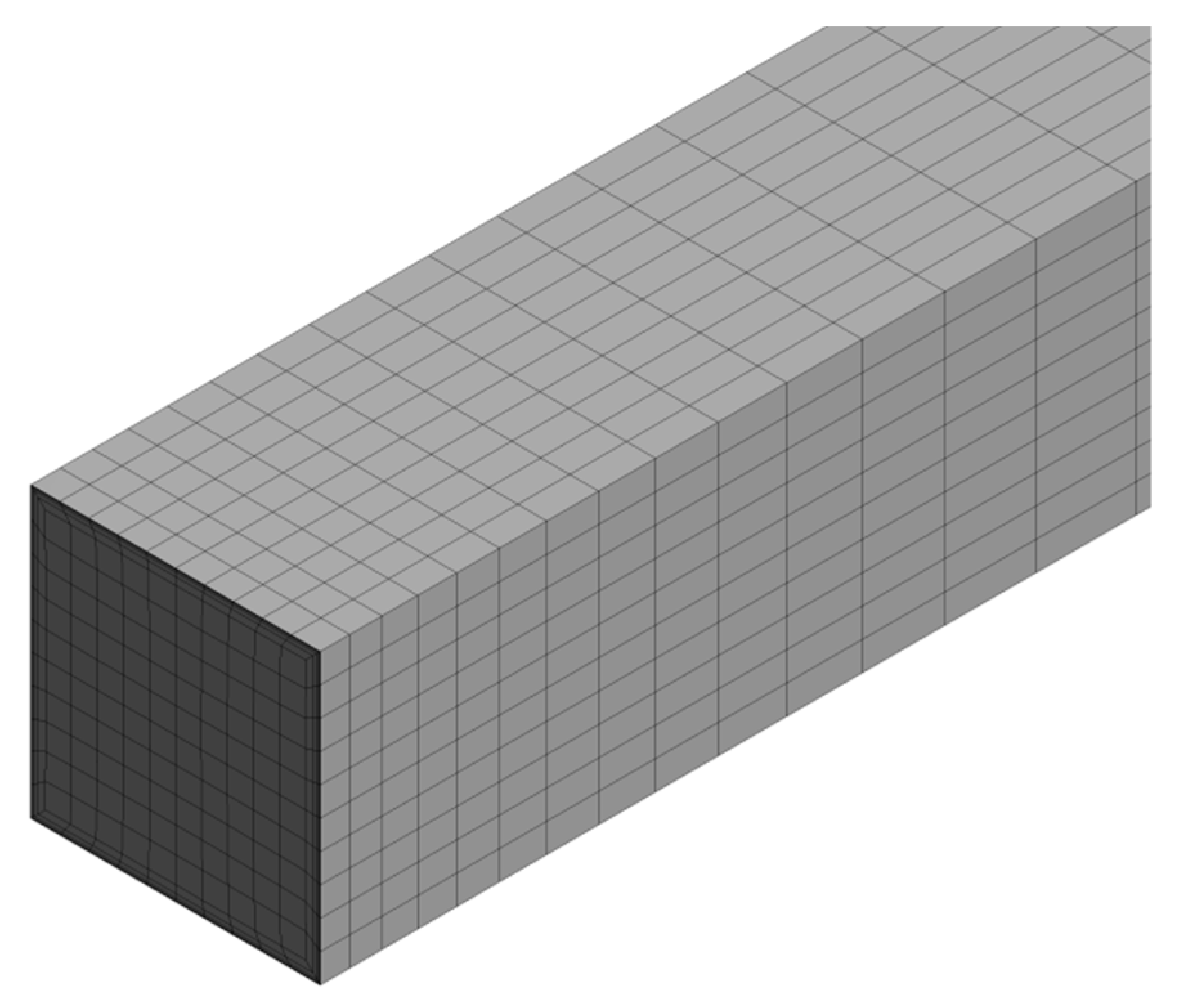
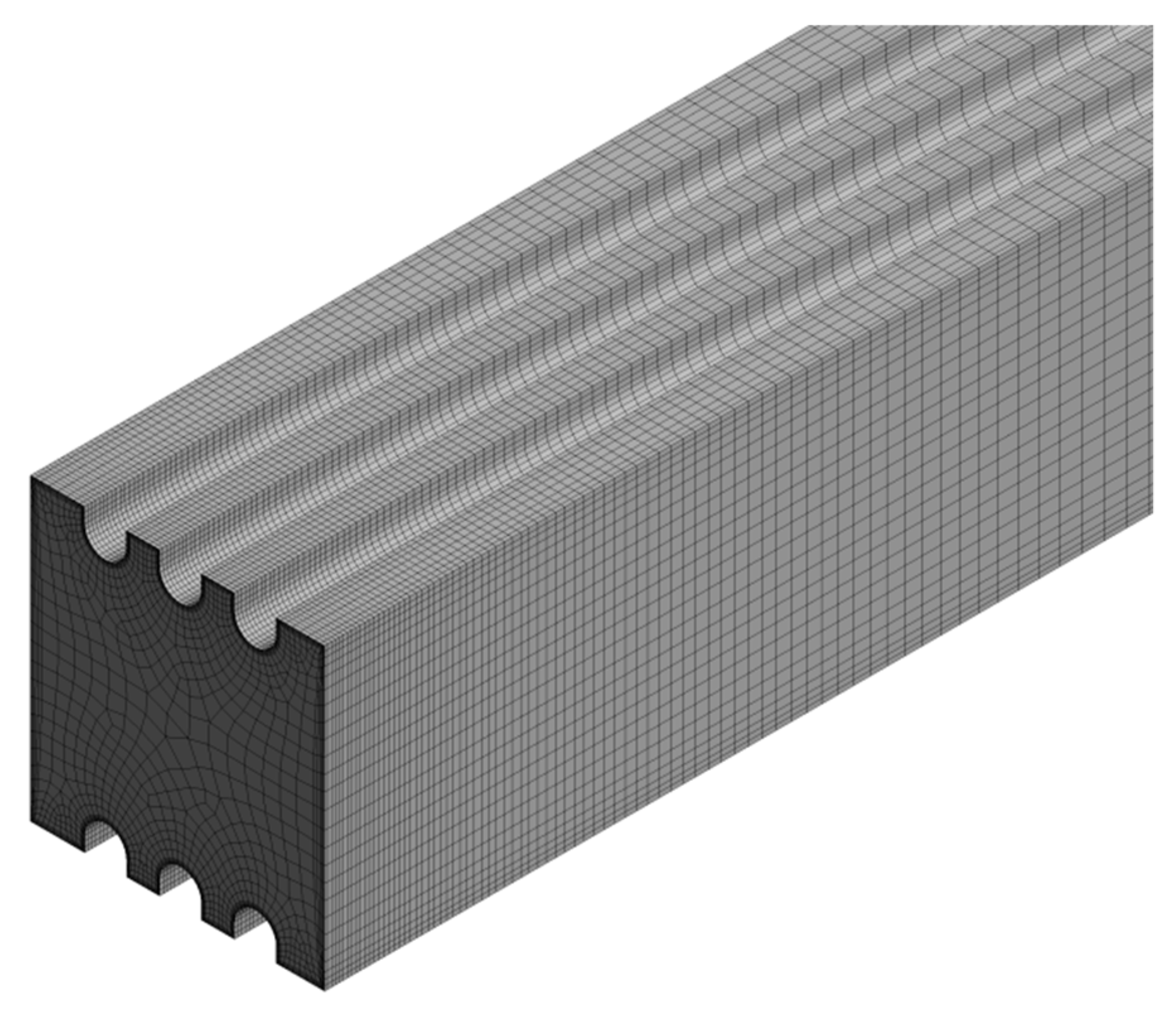
In the model geometry, the test section was a square mini channel with a horizontal microfin along 450 mm and 2 mm in width of the square channel. The constant flux boundary condition of 1000 W/m2 was applied along the wall channel. The structure microfin of this minichannel had a fin number, N = 6, fin width, Wfin = 0.28 mm, and fin height, Hfin = 0.24 mm. Nanofluids entered in the mini channel, while determining the specified mass flow rate and Reynold’s number. Because the nanofluids flowed through a horizontal channel, gravity and body force were neglected as mentioned in the section, Conservation of Momentum. Pressure outlet boundary conditions were applied in this numerical study as a reference pressure. In this study, the reference pressure was set to 0 Pa when the dynamic pressure changes were significant compared to the absolute pressure level at atmosphere pressure.
3.4. Numerical Procedure and Simulation Condition
Computational fluid dynamics (CFD) software ANSYS FLUENT 19.0 was used to solve the governing equation in Equations (17), (21) and (23). The second order upwind scheme was used to distinguish the convection, diffusion terms and other quantities generated by the governing equation. Pressure and velocity were coupled by using the semi-implicit method for pressure-linked equations (SIMPLE). The pressure interpolation scheme used in this work was the pressure staggering option (PRESTO) scheme. Convergences of iteration completion was ascertained by determining all residual variables. The residual values of the continuity and momentum equations was 10−3, whereas the energy equation was 10−6. Furthermore, the number of iterations was set to 1000.
5. Results and Discussion
The size of the domain used in this work was 22,108 mm in hydraulic diameter (Equation (1)) and 450 mm in length. The boundary conditions on the domain were mass flow inlet, wall channel, and pressure outlet. For the wall channel, a uniform heat flux of 1000 W/m2 and a no slip wall condition were applied. Numerical validation was conducted by comparing the simulation results with the established theories and correlations. Laminar flow modeling was performed using the various nanoparticle concentrations of 0.005, 0.01, and 0.1 vol.%. The numerical simulation was conducted on a square minichannel with a microfin structure at a Reynold’s number range of 150–1750.
5.1. Numerical Validation
To verify the accuracy and reliability of the numerical method, pure water was used before the nanofluid at laminar flow. Hydrodynamic and thermal validation in this study was carried out by comparing the empirical correlations for laminar flow and the results of the numerical calculations. The empirical equation used as a correlation was the Shah and London correlation [
48] for the friction factor and Nusselt number.
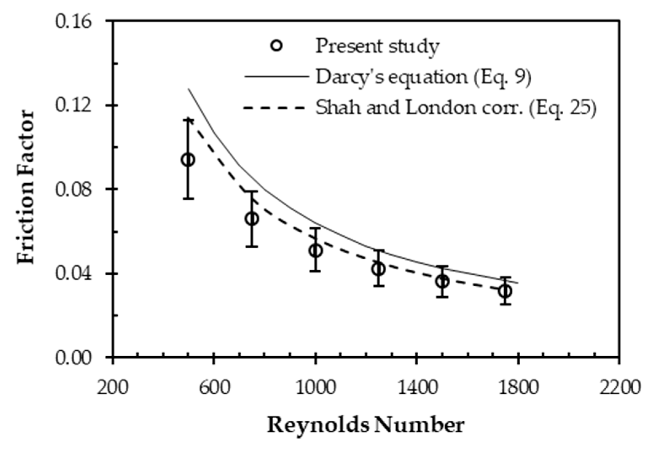
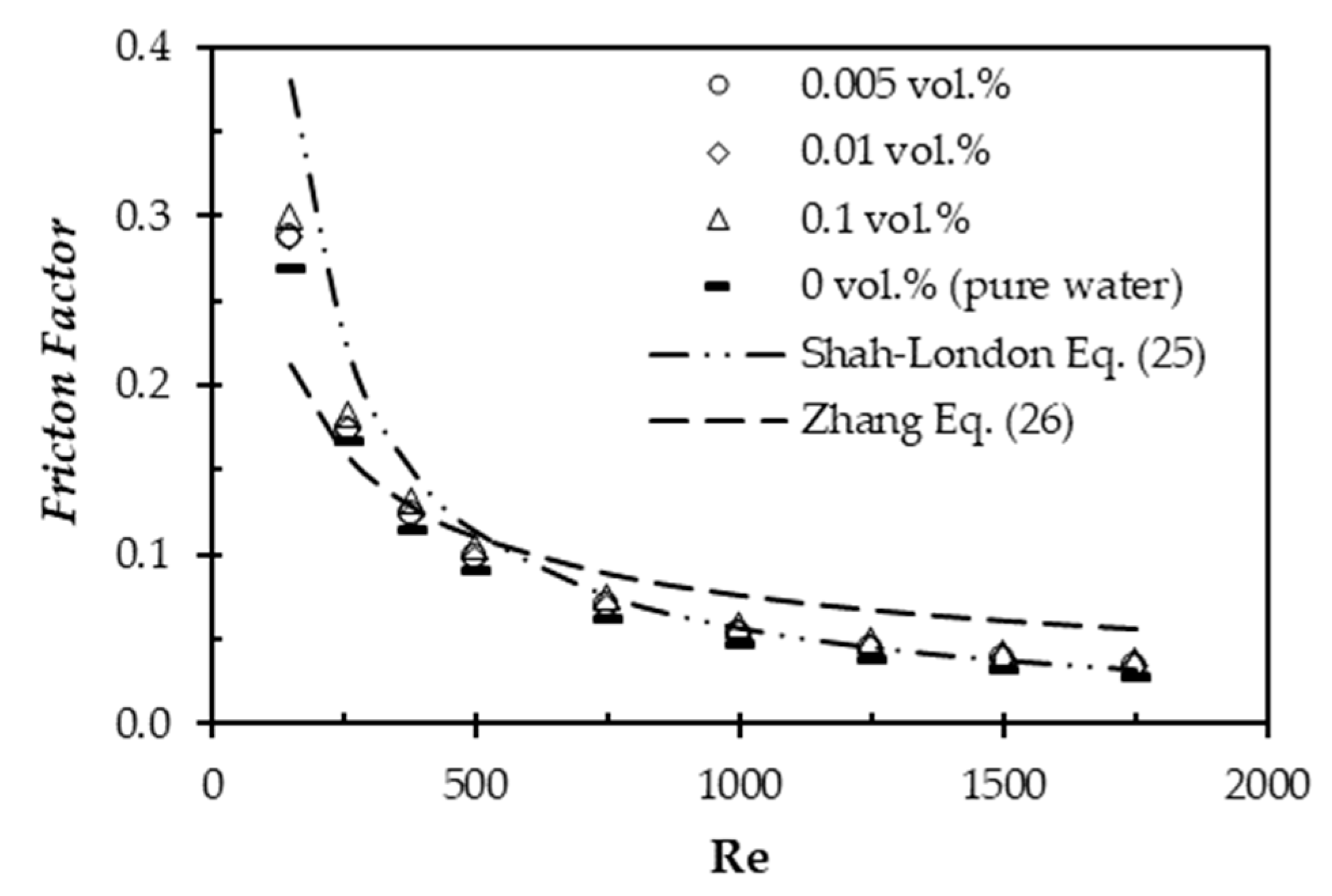
The friction factor is related to surface shear stress, which is associated with a decrease in velocity on the surface of the channel. The comparison result between numerical data in this study and the established empirical correlation is illustrated in
Figure 3. The friction factor from the numerical results was compared to the Shah and London equation [
48] for a fully-developed laminar flow in the channel.
where α is the aspect ratio, b/a (0 < α < 1). The resulting pressure drop from the numerical solution was validated by calculating the established friction factor equation in Equation (8).
As shown in
Figure 3, the resulting numerical data in this work was found to be in reasonably good agreement with the empirical correlation proposed by the Shah and London correlation [
48] and the Darcy–Weisbach equation [
46] with less than about ±0%, particularly at a higher Reynold’s number. However, it can be seen that at a lower Reynold’s number, the numerical results give a higher error of about ±20% compared to the Shah and London correlation. Darcy’s equation failed to predict the friction factor of the numerical data. The square channel and developing flow might be the reason for these unsuitable results as Darcy’s equation is generally used for a circular tube and hydrodymically fully-developed flow.
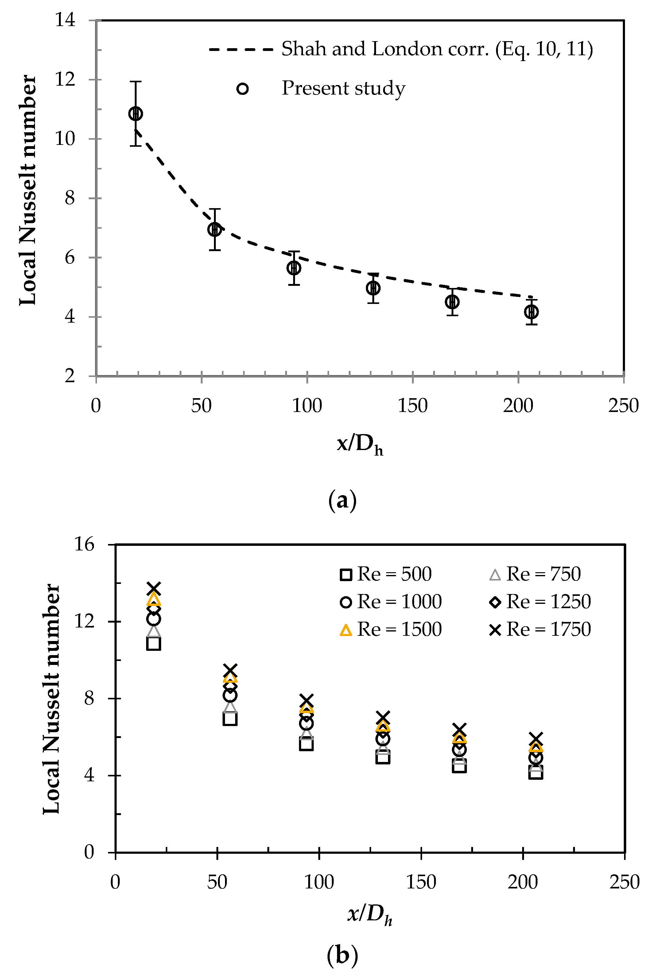
The Nusselt number was performed by comparison with the Shah–London correlation as shown in Equations (10) and (11) at thermally developing flow. The comparison of the Nusselt number calculation between the numerical result and the Shah–London correlation is shown in
Figure 4.
Figure 4a shows that the simulation results are close to the Shah–London correlation at a Reynold’s number of 500 with an error bar of 10%. In
Figure 4b, it is clear that the Nusselt number versus various Reynold’s numbers demonstrates a similar pattern. The highest Reynold’s number exhibits the highest Nusselt number along the axial direction. Therefore, it can be said that the setup of the laminar flow simulation in a minichannel is valid when compared to the reference equation. Unlike the microchannel, there was a slip velocity and temperature jump that significantly affected the velocity and temperature profiles. A higher value of the slip coefficient corresponds to a lower Nusselt number and a higher slip velocity and temperature jump [
53].
5.2. Friction Factor with an Enhancement Technique
Figure 5 shows that the friction factors in a square minichannel with a microfin using nanofluids exhibit a higher value than when using water. The friction factor also increases with the increase in nanoparticle concentration. This flow behavior could be attributed to the higher bulk fluid velocity boundary layer caused by the nanoparticles existence. Another reason for the increase in friction factor is the more significant disturbance in the flow caused by the fin structure [
29]. The characteristics of the friction factor in the minichannel with a microfin structure along the axial direction were proposed by Zhang et al. [
54] by the following expression.
However, the proposed correlation in Equation (26) failed to predict the friction factor in this present work. The earlier transition regime exhibited from the experimental data might be responsible because the numerical study cannot solve the governing equations for the transition flow regime.
The hydrodynamic characteristics of laminar developing flow are vital parameters in most noncircular duct geometries found in heat exchanger applications. The prediction of the friction factor–Reynolds product (
f Re) for developing and fully-developed flows has been studied by means of scaling analysis. Models were proposed using the asymptotic results for both the hydrodynamic entrance length and the fully-developed flow length, which is related to the hydrodynamic entrance length [
55]. The numerical results for the decline in friction factor obtained in our present work support the asymptotic results developed by previous studies.
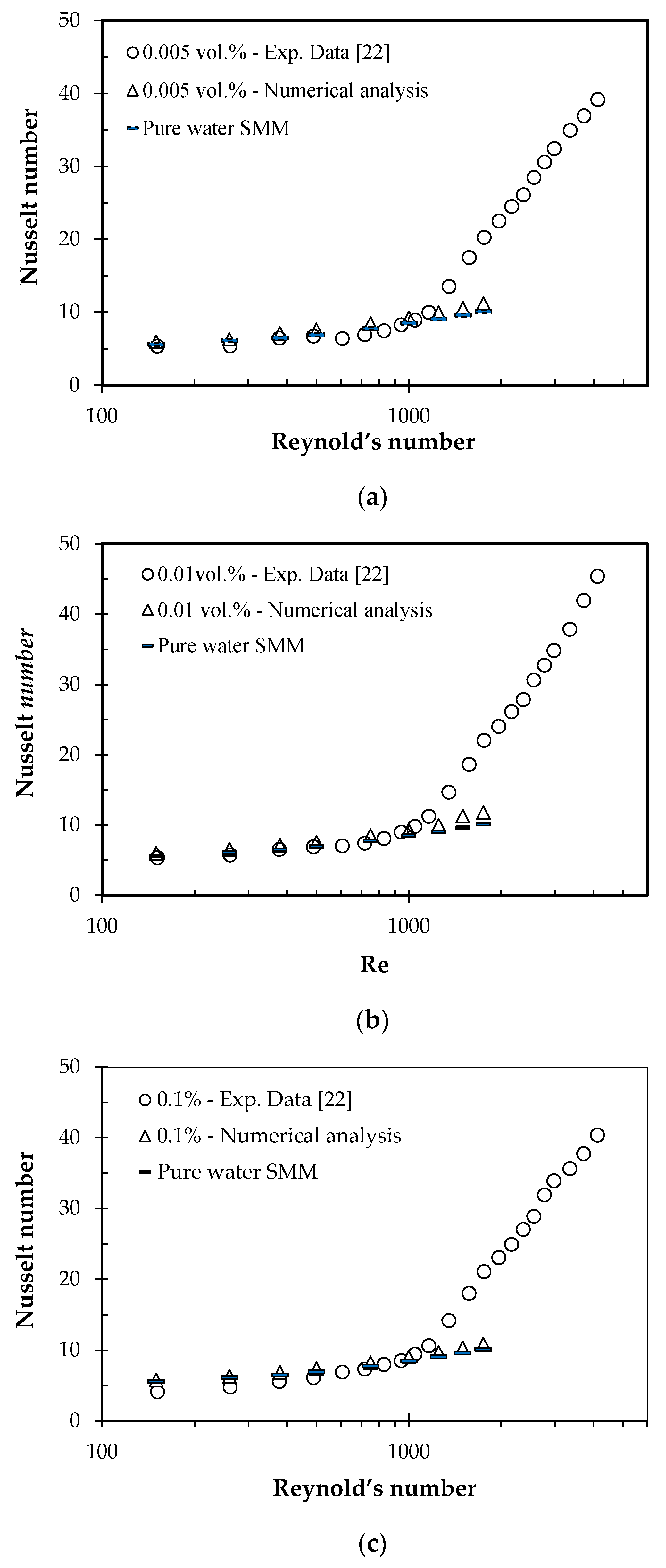
5.3. Comparison of Heat Transfer Performance between Numerical and Experimental Studies
Figure 6 demonstrates the comparison of the Nusselt number obtained from the numerical analysis and the experimental data. In this figure, all volume concentrations of 0.001 (
Figure 6a), 0.05 (
Figure 6b), and 0.1 vol.% (
Figure 6c) exhibit a discrepancy in the Nusselt number when the Reynold’s number is higher than 1200. It can be understood that nanofluids encounter an earlier transition in the minichannel with a microfin structure, even though the Reynold’s number is up to 1200. Therefore, numerical analysis cannot predict the Nusselt number in the transition flow regime because there are no facilities of the transition flow regime set-up available in the ANSYS Fluent.
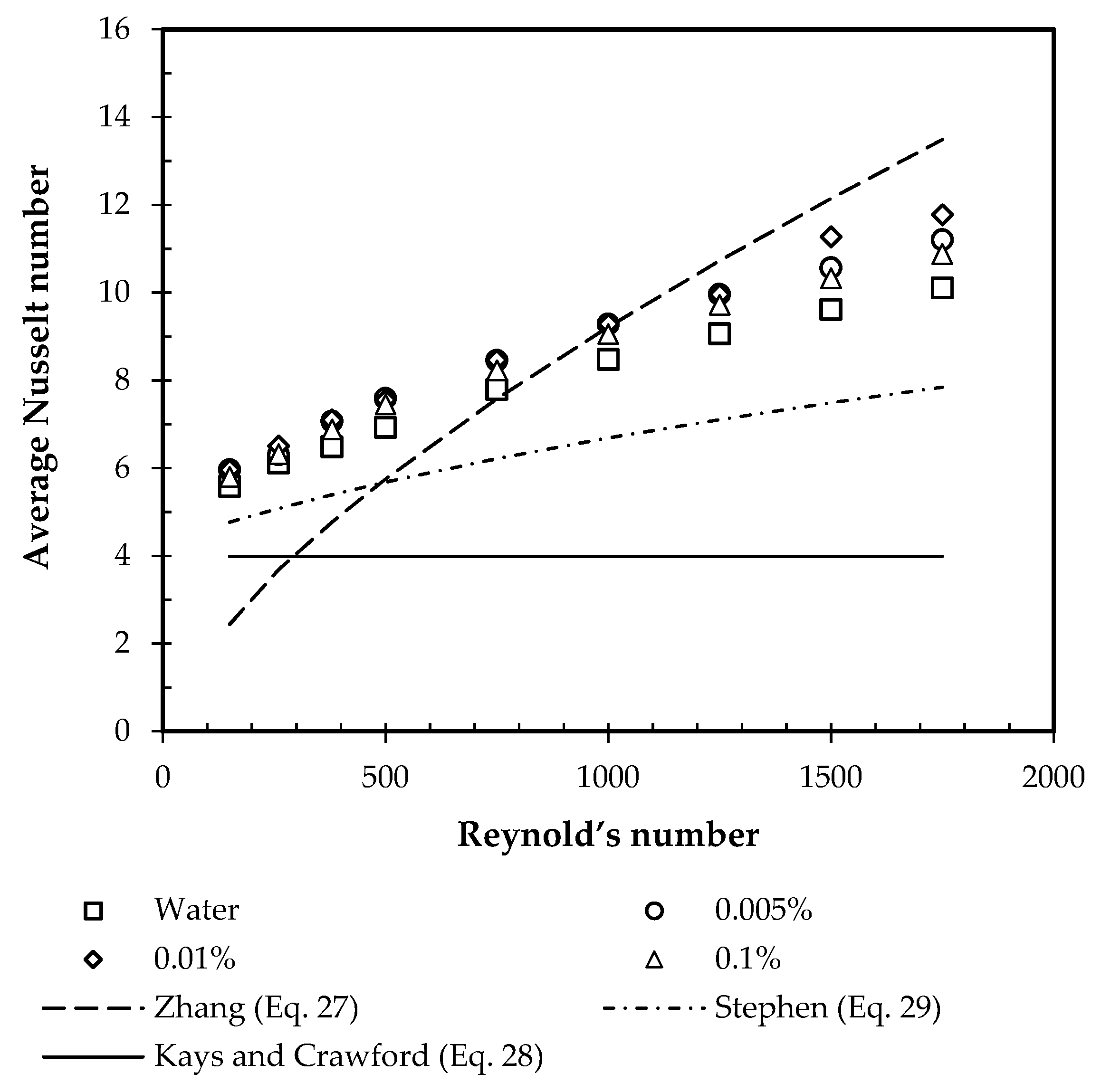
5.4. The Nusselt Number with an Enhancement Technique
Figure 6 and
Figure 7 present the correlations of the Nusselt numbers of the observed nanofluids flowing inside a square minichannel with a microfin structure compared to the previous empirical results. The empirical equations used in this work are as follows.
Kays and Crawford equation [
56]
Equation (28) is for fully-developed laminar flow in a rectangular duct with a constant heat flux condition, where α is the aspect ratio (= channel height/channel width).
Condition for simultaneously developing flow with constant wall heat flux.
It can be seen that the numerical results in this study agree well with the Stephen equation, although this correlation does not use nanofluids as the working fluid. The condition of simultaneously developing flow for the boundary condition of constant wall heat flux might be responsible for the similar convective heat transfer characteristics.
As shown in the figure, all Nusselt numbers of the nanofluids with a volume concentration of 0.01% have higher values than those of the others at the laminar flow regime. The Nusselt number increases with the increase in nanoparticle concentration for a volume fraction less than 0.01%, whereas the Nusselt number decreases with the increase in nanoparticle concentration. This indicates that the optimal heat transfer performance is at the volume fraction of 0.01%. This phenomenon is in good agreement with the results of previous experiments [
29]. However, there is a difference between this result and the other empirical result as shown in this figure. This might be due to the difference in geometry and boundary conditions between the previous published experiment and this study.
Figure 6 shows that the numerical study in this work failed to predict the Nusselt number at the transition flow regime because there is an early transition flow phenomenon in a square minichannel with a microfin structure at Re = 1200, as revealed from the previous experiment. This is understandable because there is no transition flow model to solve the governing equations in the ANSYS software. Therefore, experimental results with the transition flow regime are more trustworthy than the numerical data.
This phenomenon is considered to be due to the combined effect of increasing thermal conductivity and viscosity. Increasing particle concentration results in increased thermal conductivity and viscosity. At the beginning, increasing particle concentration can strengthen heat transfer but it can also weaken the thermal performance due to the increasing thickness of the thermal boundary layer. At a volume concentration of 0.01%, the positive effect of increasing thermal conductivity in this study is higher than the negative effect of viscosity. The exchange of energy among nanoparticles, as well as between nanoparticle channel walls from the movement of chaotic nanoparticles, increases the heat transfer performance. On the other hand, the opposite case applies at a particle concentration of more than 0.01%. As volume concentration increases, there are more nanoparticles per unit volume. In this work, the energy exchange weakens with increasing nanoparticle concentration at a certain volume fraction because the higher concentrations can limit the chaotic movements of nanoparticles.
Heat transfer enhancement can occur through using nanofluids as working fluids, and using a microfin structure. Even though nanofluid flow was at a laminar regime, a greater disturbance to the flow occurred with the microfin structure, which contributed to generating an intensely irregular movement of the nanoparticles. The stronger chaotic movement of nanoparticles was responsible for awakening a stronger energy transport between nanofluids and the channel wall that improved the heat transfer performance. Therefore, heat transfer enhancement in a laminar region is more remarkable [
54]. On the other hand, nanofluids play a key role in increasing the heat transfer coefficient. The mechanism for heat transfer enhancement was the interactions between nanoparticles, chaotic particle movements, increased transfer of thermal energy from the wall to the nanofluid flow, and the characteristics of the dispersion properties. In addition, the increased thermal conductivity and collisions between particles also play an important role in the mechanism of heat transfer enhancement.
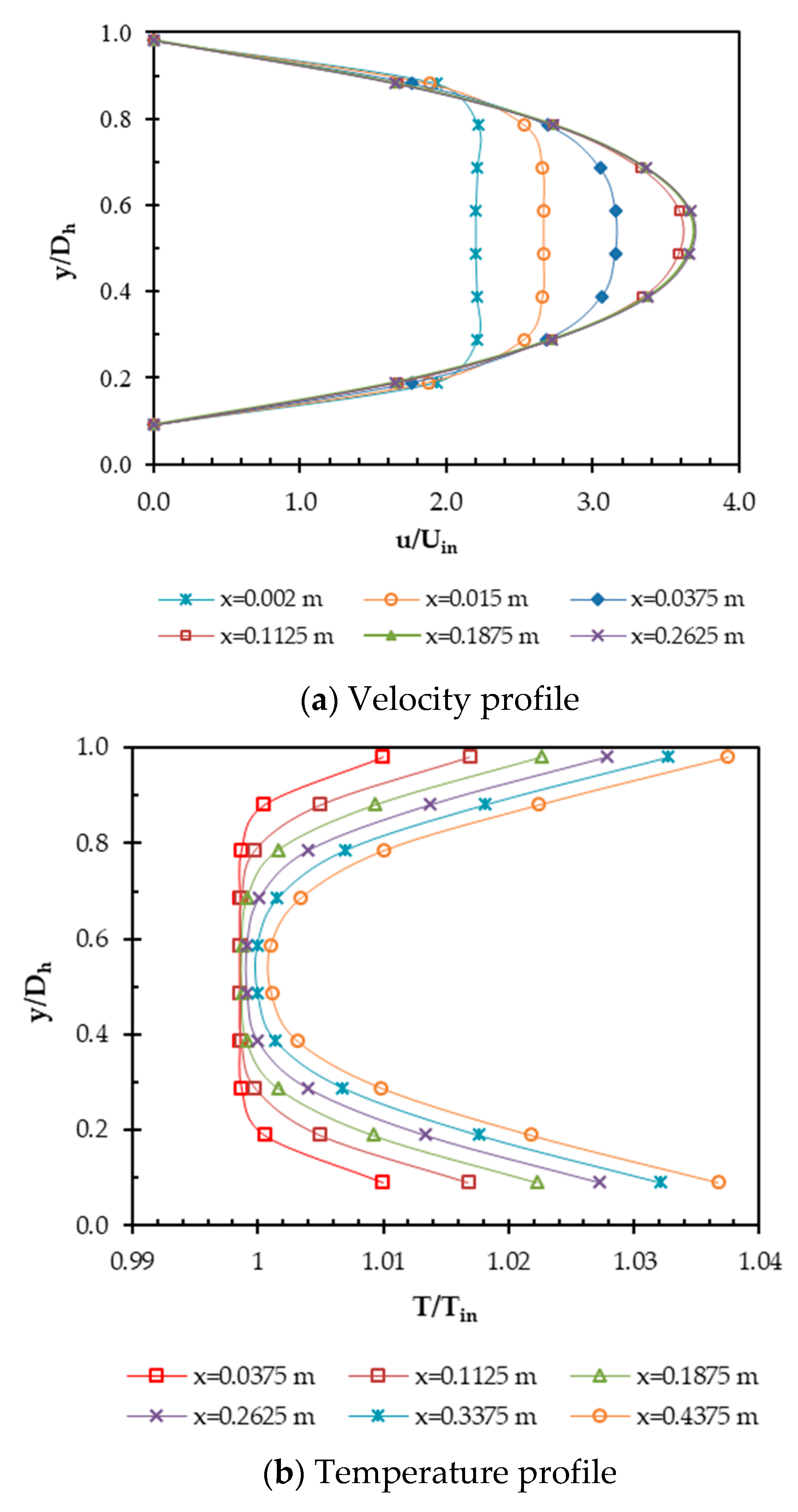
5.5. Velocity and Temperature Profile in the Radial Direction
The velocity and temperature profile in the radial direction along the axial length for a nanoparticle concentration of 0.01 vol.% and a Reynold’s number of 1000 is illustrated in
Figure 8. The velocity profile is demonstrated between hydrodynamically developing flow and when fully-developed flow occurred, as shown in
Figure 8a. The developing flow region is shown by changing of the flattened shape to a parabolic shape until there is no change in the velocity profile at
u/
Uin = ~3.8 and
x = 0.1785 m. The fully-developed flow region is also demonstrated thermally by the temperature profile as illustrated in
Figure 8b. It can be observed that the nanofluids reached thermally-developed flow at more than 0.473 m. It needs longer to reach thermally-developed flow than hydrodynamically-developed flow.
Brownian diffusion and thermophoresis influence particle movement from the wall to the centerline. This movement causes an increase in viscosity and thermal conductivity of nanofluids near to the centerline [
47]. As a consequence of these incremental thermophysical properties of nanofluids, velocity and temperature profiles are flattened, as denoted in
Figure 8. The flattened velocity and temperature profiles cause the flow of nanofluids to reach hydrodynamically and thermally fully-developed flow faster. It can be stated that the faster hydrodynamically and thermally fully-developed flow constitutes the effect of faster boundary layer thickening on the wall channel. Boundary layer thickening was due to the effect of increasing the viscosity of the nanofluids. The region that was not affected by the effect of viscosity was called as an inviscid region. This region will result in flattening of both the velocity and temperature. Although the faster boundary layer thickening on the wall channel was caused by the negative effect of increasing the viscosity of the nanofluids, thermal conductivity enhancement also occurred. The faster the boundary layer thickening occurred on the wall channel, the faster the hydrodynamically and thermally fully-developed flow. This phenomenon might be a possible mechanism for convective heat transfer enhancement of nanofluids. Other numerical studies of forced convection heat transfer characteristics in microchannels have used the thermal lattice Boltzmann method (TLBM) [
53]. Unlike the macro flows, it was observed that the maximum velocity (
Umax) at the fully-developed region was less than 1.5.
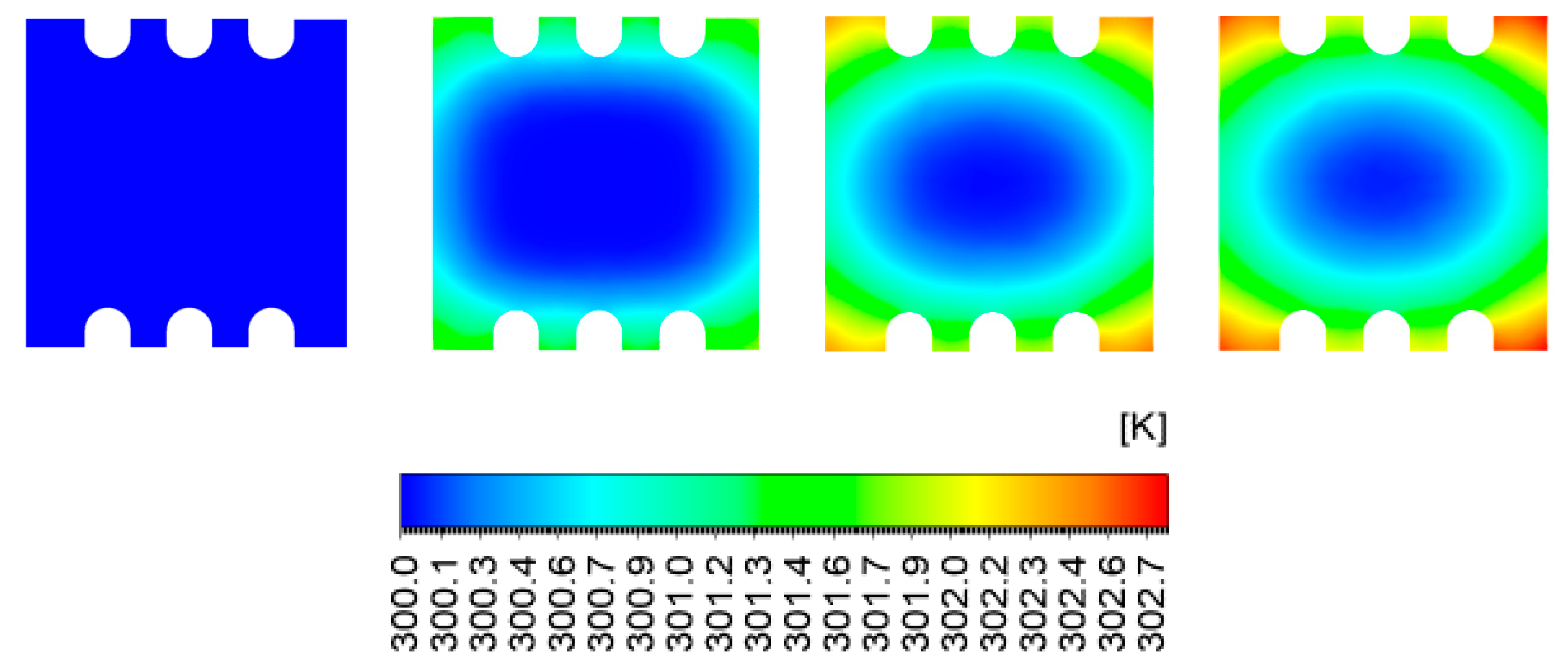
5.6. Temperature Distribution in the Axial Direction
Figure 9 shows the temperature distribution of the nanofluid at Re = 1000 and a nanoparticle concentration of 0.01 vol.%. The nanofluid is heated from the channel wall section and the temperature gets hotter along the axial distance of the pipe. In the heating process, high temperatures are reached on the wall section of the channel instead of the low temperature on the channel axis. The nanofluid temperature at a nanoparticle concentration of 0.01% is lower than the others. This phenomenon occurs because, at a volume concentration of 0.01%, the positive effect of increasing thermal conductivity is higher than the negative effect of viscosity.
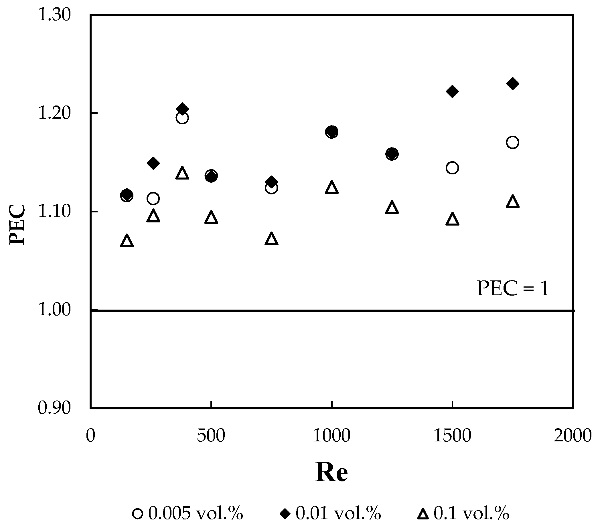
5.7. Performance Evaluation Criterion (PEC)
To observe how large the effect of thermal conductivity and viscosity was, the performance evaluation criterion (PEC) was used in this work. PEC is defined as the ratio of the enhanced heat transfer performance to the energy losses. This parameter gives an overall performance comparison to obtain the performance features of the enhanced heat transfer in nanofluids flowing inside a square channel with a microfin structure based on the consumption of pumping power. The performance evaluation criterion can be expressed as follows.
Figure 10 demonstrates the PEC values of nanofluids at different volume concentrations. It was found that the baseline data was the result of testing on a plain minichannel. As shown in this figure, the PEC value has an irregular magnitude at each Reynold’s number. In addition, all PEC values were higher than 1.0, indicating that adding nanofluids into a square minichannel with a microfin structure increased the heat transfer. Among the observed nanofluids, a nanoparticles concentration of 0.01 vol.% had the highest PEC value of 1.23 at Re = 1750. In general, all nanofluids demonstrated enhancement of heat transfer without a large decrease in pumping power. It can be concluded that although using nanofluids as the working fluid in a square minichannel with a microfin structure can increase the Nusselt number, it is also accompanied by a high pressure drop.
Dispersion of nanoparticles will change the thermophysical properties of the nanofluids. As a consequence, this influences the ratio of heat transfer enhancement to pumping power, called the performance evaluation criterion (PEC) [
57]. If the PEC value is lower than 1, then the thermal system is not feasible for use in heat transfer enhancement, as the heat transfer enhancement is less than the pumping power needed. If the PEC magnitude is equal to 1, then the thermal system does not have an impact on increasing heat transfer. If the PEC is higher than 1, then the thermal system is feasible for use in practical applications. This is because the heat transfer enhancement is higher than the pumping power required.
The above-mentioned results revealed that the dynamics and heat transfer analysis, as well as thermal performance enhancement, inside a hybrid thermal system that combines nanofluids and a microfin structure inside a square minichannel, can be investigated by numerical study. The comparison between the numerical result in this work and experiment data from previous studies has been discussed and shows a very good agreement at the laminar flow regime, including the PEC value. This numerical study failed to predict the Nusselt number at the transition flow regime because there was an early transition flow phenomenon in the square minichannel with a microfin structure at a Reynold’s number of approximately 1200, as reported by Zhang and co-workers [
29].

 ,
, 


