A Novel Photovoltaic Virtual Synchronous Generator Control Technology Without Energy Storage Systems

1
Information Engineering and College of Electrical, Lanzhou University of Technology, Lanzhou 730050, Gansu Province, China
2
State Key Laboratory of Power Transmission Equipment & System Security and Technology, ChongQing University, Chongqing 400044, China
3
Wind Power Technology Center, State Grid Gansu Electric Power Corporation, Lanzhou 730070, Gansu Province, China
*
Author to whom correspondence should be addressed.
Energies 2019, 12(12), 2240; https://doi.org/10.3390/en12122240
Submission received: 20 February 2019
/
Revised: 18 May 2019
/
Accepted: 3 June 2019
/
Published: 12 June 2019
(This article belongs to the Special Issue Emerging Converter Topologies and Control for Grid Connected Photovoltaic Systems)
Abstract
:Photovoltaic virtual synchronous generator (PV-VSG) technology, by way of simulating the external characteristics of a synchronous generator (SG), gives the PV energy integrated into the power grid through the power electronic equipment the characteristics of inertial response and active frequency response (FR)—this attracts much attention. Due to the high volatility and low adjustability of PV energy output, it does not have the characteristics of a prime mover (PM), so it must be equipped with energy storage systems (ESSs) in the DC or AC side to realize the PV-VSG technology. However, excessive reliance on ESSs will inevitably affect the application of VSG technology in practical PV power plants (PV-PPs). In view of this, this paper proposes the PV power reserve control type VSG (PV-PRC-VSG) control strategy. By reducing the active power output of part of the PV-PPs, the internal PV-PPs can maintain a part of the active power up/down-regulation ability in real time, instead of relying on external ESSs. By adjusting the active reserve power of this part, the output of the PV-PPs can be controlled within a certain range, and the PV-PPs can better simulate the PM characteristics and realize the FR of the grid by combining the VSG technology. At the same time, the factors affecting the reserve ratio are analyzed, and the position of the voltage operating point in PRC mode is deduced. Finally, the simulation results show that the proposed control strategy is effective and correct.
1. Introduction
China’s new-generation energy revolution advocates the development of non-fossil energy, and PV energy has become an important part of non-fossil energy due to its inexhaustible advantages. It is estimated that in 2035, photovoltaic virtual (PV) energy will account for 26% of total installed capacity and 14% of electricity generation [1].
Power system frequency is an important standard to reflect the power surplus and deficiency of a power system. Frequency response control mainly reflects the power support function of source side to grid side. The influence of large-scale PV power plants (PV-PPs) on power system frequency is mainly reflected in two aspects [2,3,4]:
- Reduce the equivalent moment of inertia of the power system. The PV cell is a static original, which does not have any rotating standby. After being connected to the power grid, the original equivalent inertia will be less;
- The primary frequency response capability of the system is weakened. Under the action of maximum power point tracking (MPPT), the PV output is uncontrollable and cannot provide power support for the system.
It is obvious that large-scale PV-PPs will weaken this support after they are connected to the power grid [5,6,7]. The proposal and promotion of virtual synchronous generator (VSG) control technology can effectively solve the above problems and, at the same time, can give the PV grid-connected system the ability to participate in the frequency and voltage regulation of the power grid independently [8,9,10]. However, the PV system active power output changes with the external environment (including solar irradiance and temperature) under the effect of maximum power point tracking (MPPT). Since the active output is not controllable, the traditional VSG control strategy cannot be directly used in PV systems. Existing related research in joining the ESSs to the DC or AC side of the PV system [11,12] can effectively solve the above problems. By controlling the charging and discharging of ESSs, the effect of controlling PM output can be simulated in a short time, but it will be affected by the physical constraints of the ESSs. In reference [13], a 50 kW × 30 min lithium-ion battery pack is used to connect a PV array (installed capacity of 500 kW) DC side, and active frequency response is realized by controlling the output of the ESSs. However, any benefit brought by the ESSs to the power grid is based on the economic cost of ESSs [14].
In large-scale PV-PPs such as Hexi New Energy Base in GanSu Province, China, limited by the current energy storage technology level, ESSs cannot be widely used in PV-PPs, and the charging and discharging efficiency is low. Frequent charging and discharging not only makes the energy utilization rate lower but also affects the service life of the ESSs, resulting in greater economic losses. PV-power reserve control (PRC) maintains a part of the power up/down capability by reducing the output of the PV system [15,16,17,18,19,20] and participates in the power system frequency response in combination with inertial response control and droop control, which is called fast frequency response (FFR) or active power control (APC) [2,21,22]. However, compared with the VSG control method, the VSG is a direct simulation of the internal potential phase motion and its basic inertia and damping characteristics of the SG, and it is the simplest and most effective way to realize the characteristics of the traditional SG. In addition, in the previously published works on PV-PRC, there are different views of whether the voltage operating point should be located to the left or right of the maximum power point voltage () in PV-PRC mode. In addition, the PV-PRC model means that a part of the photovoltaic energy is wasted, but there is little work on how to choose the appropriate reserve ratio.
Aiming at the above problems, this paper takes the two-stage PV grid-connected system as the research object. The DC/DC and DC/AC converters implement PV-PRC/MPPT and VSG control respectively. We named this control method as the PV power reserve control type VSG (PV-PRC-VSG) control technology. In this paper, the traditional PV-PRC and PV-VSG are combined and further improved. The main contributions are as follows:
- Propose a new PV-VSG implementation method, which maintains a part of the active power up-regulation capability by operating the PV system in PRC mode and combines the VSG technology to enable the PV system to support sudden power shortages in the power system. The control method is called the PV power reserve control type virtual synchronous generator (PV-PRC-VSG) technology;
- Considering the actual project, in order to ensure the reliable and efficient operation of the inverters, two voltage operating points in PV-PRC mode are analyzed in detail, and the result that the voltage operating point in PRC mode should be located on the right side of the maximum power point voltage is achieved;
- Based on the requirements of the State Grid for wind abandonment and PV energy abandonment and the active support capability of PV-VSG, the upper limit of the reserve ratio in PV-PRC mode is obtained.
In Section 2 of the paper, the traditional PV-VSG technology is introduced in detail. The implementation strategy of PV-PRC and the position of the voltage operating point are elaborated in Section 3. The proposed PV-PRC-VSG control technology and the range of the reserve ratio in PV-PRC mode are described in Section 4. In Section 5, the validity of the proposed method is verified by simulation experiments under various operating conditions.
2. Modeling and Analysis of PV-VSG
2.1. Principle and Embodiment of the VSG
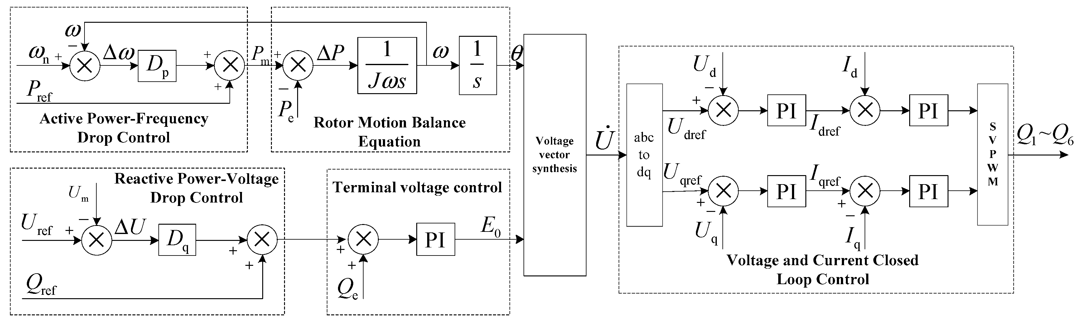
VSG control can be divided into active loop control and reactive loop control from the function and control target. Its active loop includes active frequency droop control and inertial response control, which mainly realizes the function of independent FR. The reactive loop consists of reactive power-voltage droop control and end-voltage closed-loop control, which realizes automatic voltage regulation and voltage amplitude control of the VSG [23]. The basic mathematical model of the VSG is as shown in Equation (1). The VSG control block diagram controlled by the mathematical model is shown in Figure 1.
where is the moment of inertia, and are the given values of active power and reactive power, and are the actual output values of active power and reactive power, and are the rated and actual values of electric angular velocity, and are the droop coefficients of active and reactive loops, and are the actual and given values of grid voltage amplitude, is the internal potential amplitude of the VSG, is the integral coefficient, and it can be replaced by PI regulator.
2.2. Traditional PV-VSG Technology
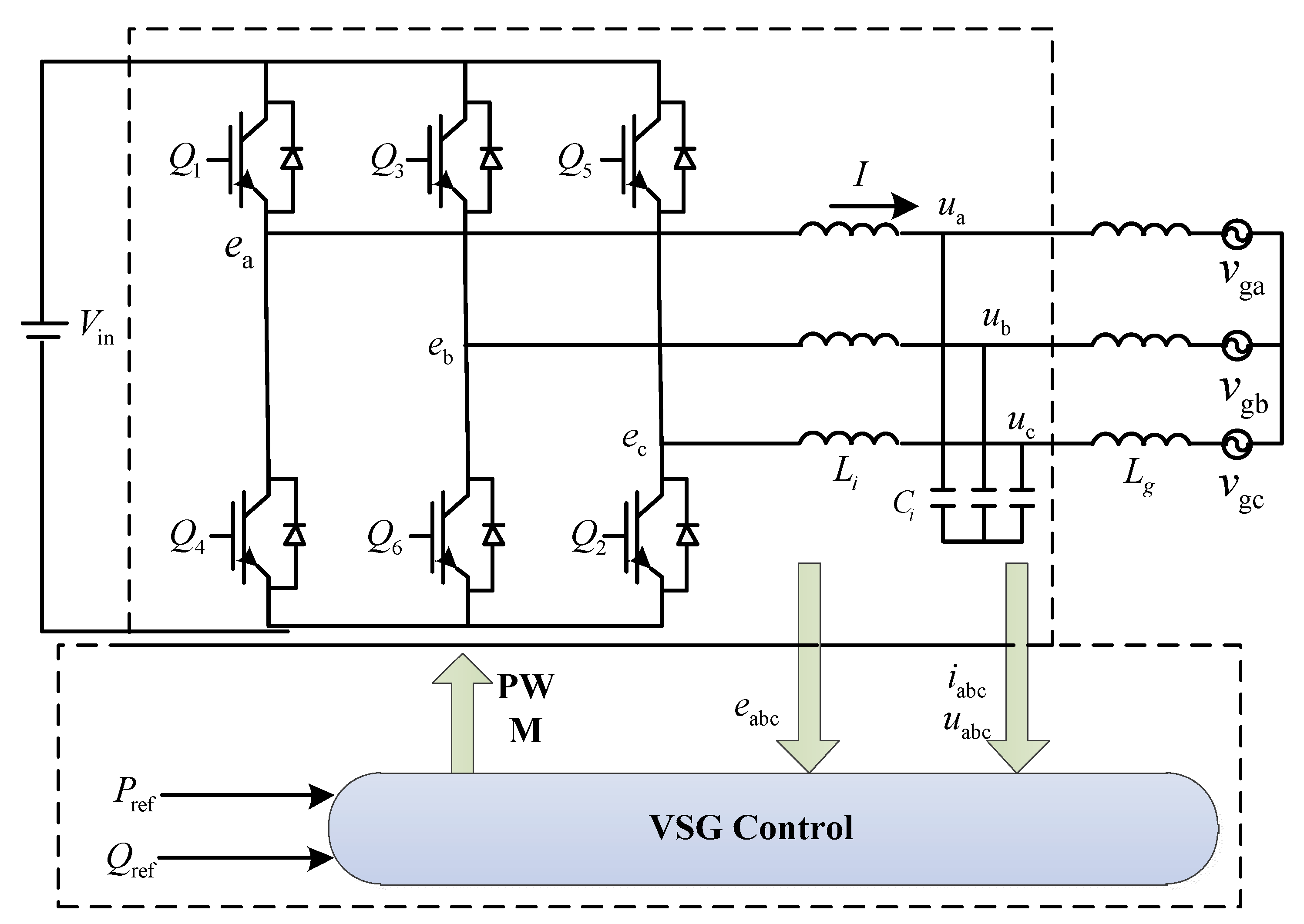
In this paper, the two-stage grid-connected PV system is taken as the research object, as shown in Appendix A. Because the control objectives of DC/DC and DC/AC converters are different, as shown in Table 1, the control method shown in Figure 1 cannot be applied to the two-stage grid-connected PV system. In addition, if the PV system operates in MPPT mode, the output of the PV system cannot be controlled, and the premise of VSG implementation is that the system must maintain a reserve power, then it cannot achieve autonomous frequency and voltage regulation.
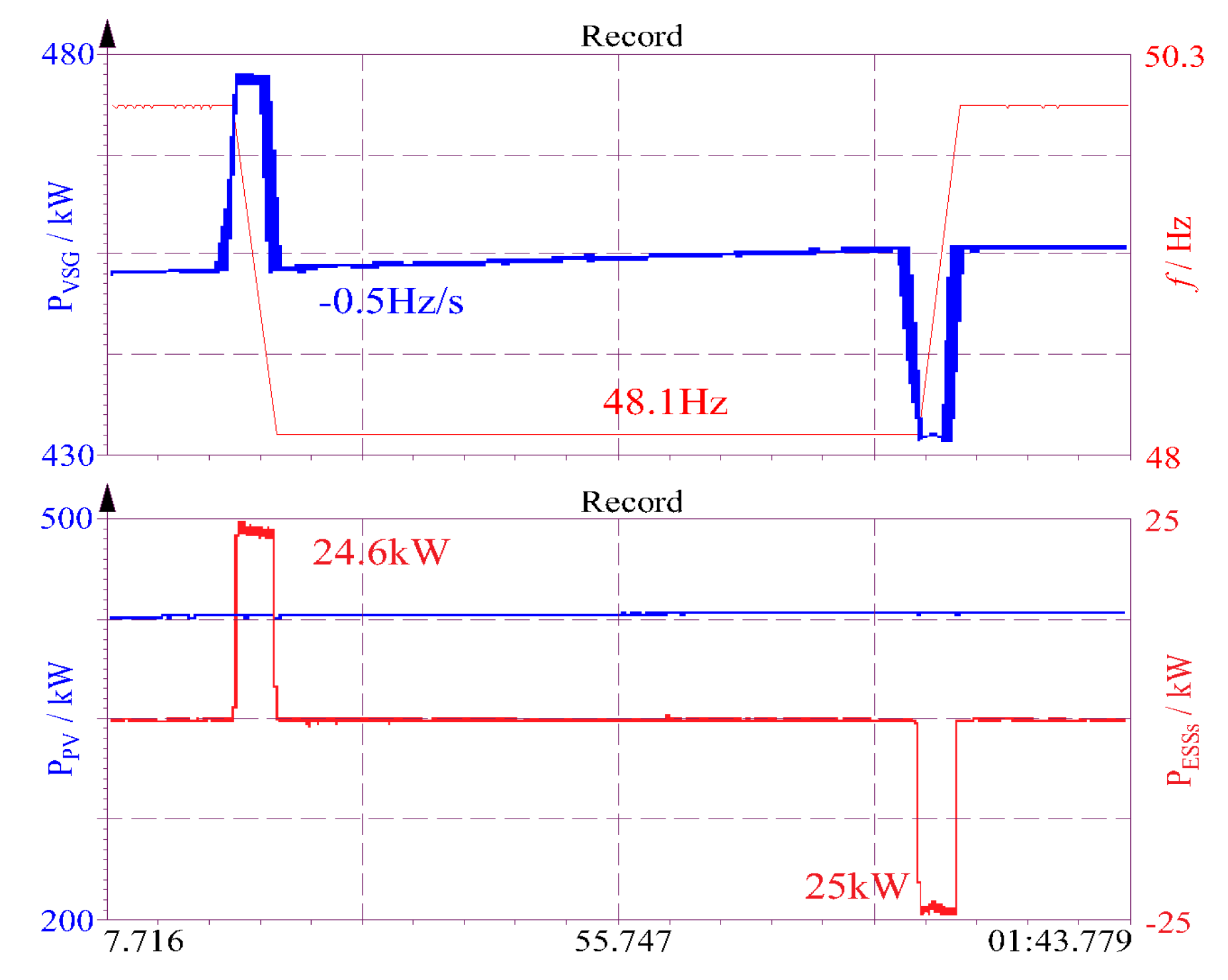
Figure 2 shows that for the control effect diagram of above method in reference [13], when the grid frequency changes suddenly, PV output power remains unchanged, and ESSs regulates output power to participate in grid FR. It is noteworthy that the active support provided by PV-ESSs is constrained by the allocation of a capacity cap and support time during the whole frequency decline stage. In addition, the addition of ESSs will greatly increase the construction cost of PV-PPs. The operation of PV-PRC can effectively reduce the above problems.
Therefore, in order to apply VSG control technology to the two-stage grid-connected PV system, it is necessary to solve the active standby problem and improve the control algorithm. External ESSs can effectively solve the above problems. The ESSs mainly undertake the reserve capacity required by FR. After adding ESSs, the Equation (1) is converted to:
3. PV-PRC Principle and Voltage Operating Point Analysis
3.1. Analysis of PV Generator Output Characteristics
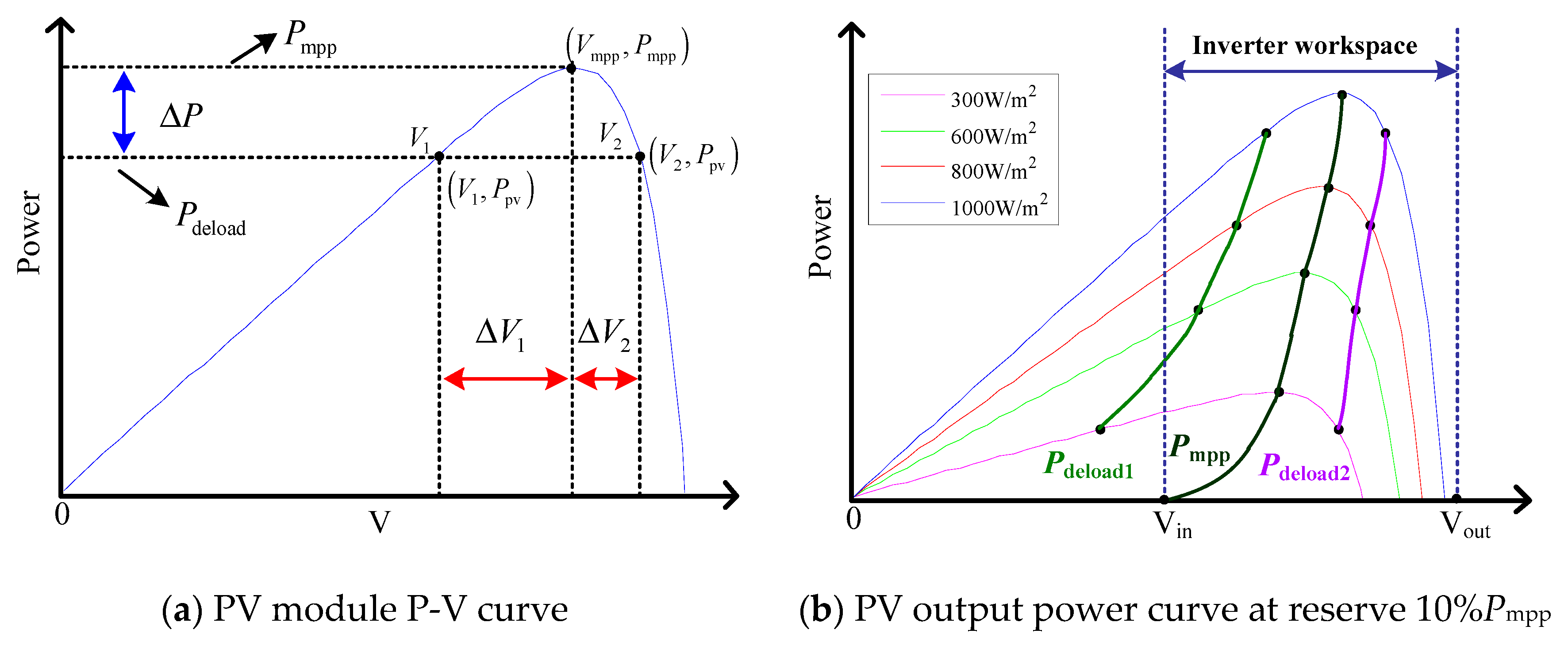
The output P–V characteristic curve of the PV module is as shown in Figure 3a. In Figure 3a, there is a unique maximum power value ; is the output power value of the PV system in PRC mode; in PRC mode, the PV system maintains a part of the real-time active power up-regulation capability, as shown in Equation (3), is called the reserve active power of the PV system.
As shown in Figure 2a, the output power of the PV system corresponds to two voltage operating points and in the non-MPP. The relationship between , and is shown in Equation (4). As shown in Equation (4), the same active reserve is implemented in PRC mode. Since the curve corresponding to the side has a steeper gradient, the voltage regulation range on the side is much smaller than that on the side (i.e., ), which will bring the faster response speed.
where is the lowest PV output voltage that can make the inverter work normally; is the maximum input voltage that the inverter can withstand; is the PV output power when PRC mode is operating on the side; is the PV output power in MPPT mode; and is the PV output power when PRC mode is operating on the side.
In addition, whether operating in MPPT mode or PRC mode, ensuring the safe and reliable operation of the inverter is the necessary prerequisite for realizing grid-connected PV power generation. As shown in Figure 3b, the PV output voltage in the region can make the inverter work normally. If the output voltage of the PV generator is not in this area, the inverter will go into shutdown or standby state. If PRC mode runs on the side, when the irradiance changes from 600 to 300 W/m2, the PV output voltage will not be in the workspace of the inverter. However, when running on the side, the voltage output is always in the operation area of the inverter.
Therefore, considering the response speed of PRC operation and the adjustable reserve capacity and ensuring the safe and efficient operation of the system, the ideal working area is expected to work on the right side of , namely the side.
3.2. PV-PRC Implementation Analysis
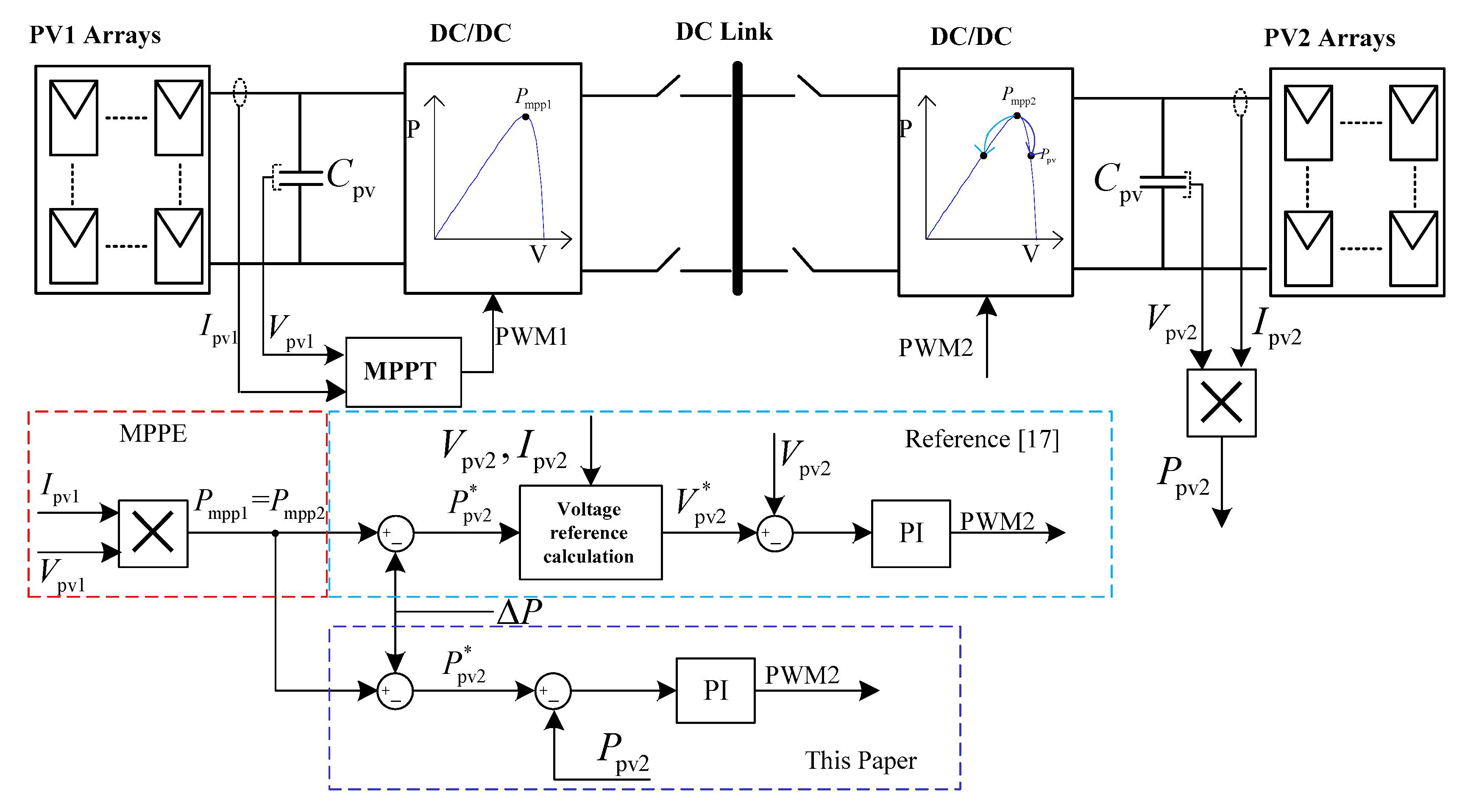
Equation (3) shows that the premise of introducing active reserve is that the current maximum output power value is a known amount. Therefore, the maximum power point estimation (MPPE) link is necessary for the PV-PRC operation, and the active power can be introduced when the MPPE link is found to be . For the sake of simplicity, the MPPE method in the reference [17] is used, as shown by the red dashed box in Figure 4, taking two sets of PV modules or arrays of the same model and quantity as an example. When operating under the same operating conditions, PV1 operation in MPPT mode, its output power can be used as the available power value of PV2 (). However, in [17], the PV output power is controlled by controlling the output voltage. The calculation of the voltage command in the process leads to a cumbersome control process. In view of this, this paper improves it by using direct power control to control the output power. In addition, in this kind of control mode, through the lowest voltage limit, the PRC runs with the side, and the control block diagram is shown in Figure 4.
4. PV-PRC-VSG Control Strategy and Reserve Ratio Analysis
In PRC operation mode, a part of the power up-regulation capability is maintained in the PV system, so that the output of the PV system can be adjusted within a certain range, and the regulation of the reserve power has the same effect as the charging and discharging of the energy storage system, and the active output can be adjusted. With the VSG technology, the inertial response and the participating power system primary frequency response can be realized. In this mode, the output power of the virtual prime mover is as shown in Equation (5).
Equation (5) can be reduced to:
where from left to right are PV output power, inertial response process demand power and primary frequency modulation demand power.
Define , where is the required power for frequency response.
Assuming that the PV system operates in PRC mode initially and maintains a certain active reserve , when the frequency change of the grid is detected to exceed the dead zone ( Hz), the required power for the PV system to participate in frequency regulation is calculated through the VSG control link. Then, by release or increasing the reserve power, it can participate in the frequency regulation of the power grid to provide power support for the power grid. The control block diagram of the whole system is shown in Figure 5.
The PRC operation mode of the PV system essentially abandons part of the PV resources, which is in contradiction with the efficient use of energy and relevant national network codes. However, considering that the realization of PV-PRC-VSG technology can improve the stability of the power system, enhance the acceptance of the power grid to PV energy, and save the investment of ESSs, it is necessary to keep the power reduction within a certain range, and the proportion of the power reserve in the actual operation process is mainly constrained by the following factors:
- Relevant regulations of the State Energy Administration pointed out that in solving the problem of clean energy consumption, the proportion of PV abandonment and power limitation will be reduced year by year. By the end of 2020, the problem of abandoned wind and PV will be basically solved nationwide (the abandoned water/wind/PV abandonment rate of the three northern regions will remain below 10%, and that of other regions will be below 5%).
- Analysis of the PRC mode applicable period: Generally, the output of a PV power plants is like a “”. At the initial and end moments, less PV energy is injected into the power system. The generating units in the power system are mainly undertaken by the SG (thermal power or hydropower). At this time, the equivalent inertia and primary frequency response capability of the system are relatively sufficient, and there is no active reserve () in the PV system. In order to maximize energy utilization, the PV system operates in MPPT mode. With the increase of irradiation intensity, the output of the PV system increases gradually. The power system uses thermal power to regulate peak load. With thermal power cut out of the power grid, the equivalent inertia and primary frequency response ability in the power system are greatly reduced. The PV system reduces active output, maintains active reserve (), and participates in frequency response of the power grid.
- The relevant requirements for PV-VSG to participate in primary frequency response stipulate that when the active power output of PV-VSG is greater than , it should have primary frequency response capability; when the frequency deviation exceeds the dead zone ( Hz), PV-VSG should adjust the active output to participate in primary frequency response; in the primary frequency modulation process, the upper limit of active power can be increased at least , and the upper limit of active power can be reduced at least .
To sum up, considering the limitation of abandoning PV energies and the requirement of the VSG for primary frequency modulation, it is more appropriate to reduce power by . During the operation of the power system, when the system frequency increases, the active output of the PV system further reduces the frequency change of the response system by increasing the value of . When the system frequency decreases, the value of of the PV system needs to be reduced to release the reserve active power. It is noteworthy that when , there is no active power up-regulation ability in the PV system. In addition, is still limited by the upper limit. When increases to , it cannot be increased any more. As shown in Equation (7), because of the limitation of active reserve capacity, the ability of PV-PRC-VSG to participate in primary frequency regulation is limited.
where is a reference value of reserve power during primary frequency response.
5. Simulation of Proposed Method
To verify the effectiveness of the proposed control strategy, the corresponding simulation model was built in MATLAB/Simulink. The model topology adopts the grid-connected structure of the PV system in Figure 2. The corresponding experimental verification was made for a DC/DC inverter working in PRC mode and DC/DC and DC/AC inverter coordinated control participating in power system frequency response.
5.1. PV-PRC Simulation and Analysis
Firstly, the PRC operation control strategy of the DC/DC side proposed in the second section is simulated and analyzed. Taking the parameters of a single 240-W PV module (JLS60P240W) as an example, the parameters of PV modules are shown in Table 2. The maximum power value of the PV module is calculated in the MPPE process, and then the active reserve is introduced. For the convenience of calculation, the reserve ratio (R) is introduced. The value of R can be calculated by Equation (8). In the operation process control, R is the direct control object.
where: -Open circuit voltage; -short-circuit current; -Maximum Power Voltage; -Maximum Power Current; -temperature coefficient of open circuit voltage; -temperature coefficient of short circuit current.
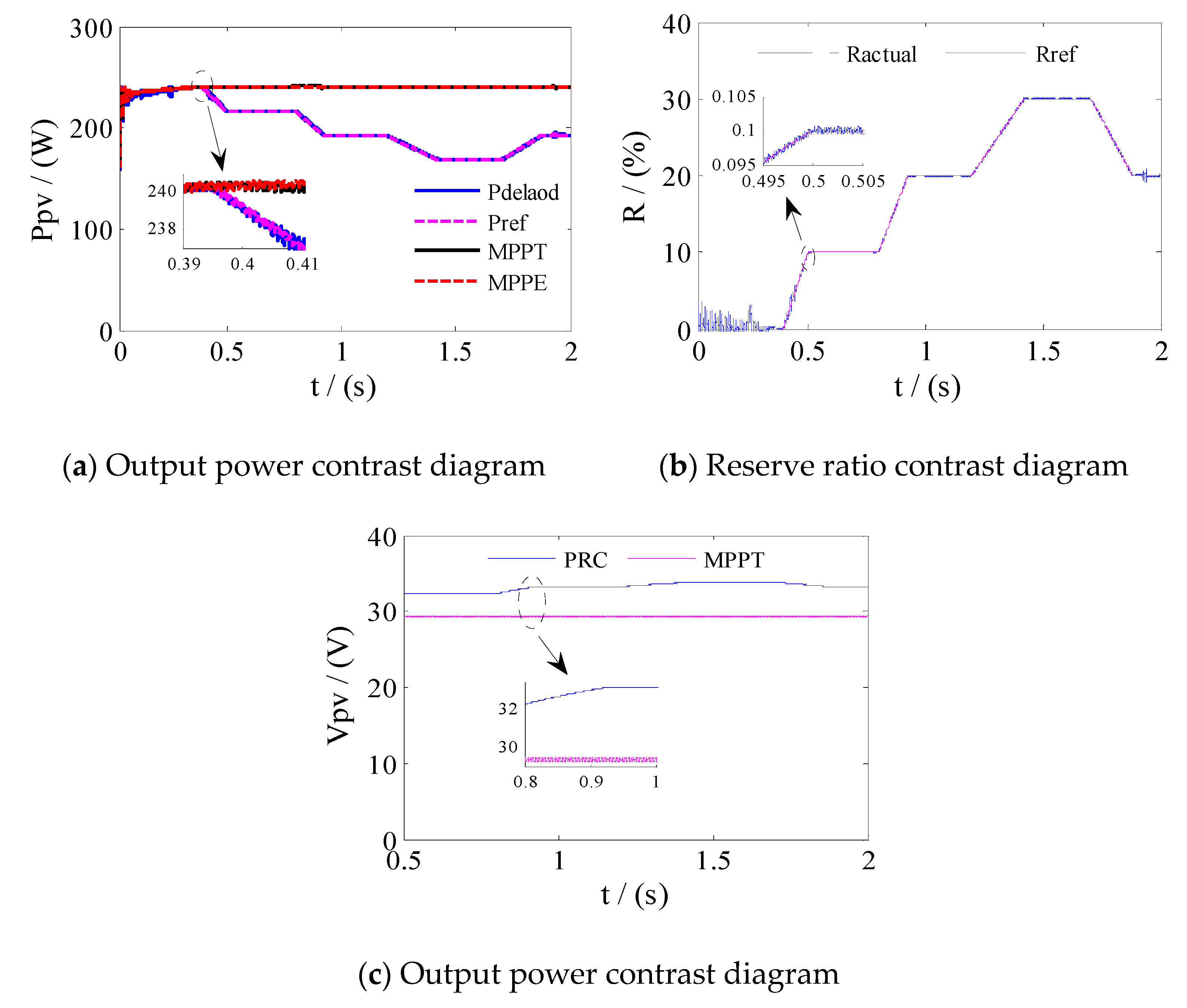
The primary task of PRC operation is to calculate the value of at each moment; that is, the MPPE process. MPPE plays a vital role in the whole PRC operation process, which directly affects the accuracy of the power reserve. In Figure 6a, the red dotted line is the maximum output power (actual value) of the PV system in MPPT mode, and the black dotted line is the value calculated by MPPE, which deviates little from the actual value, thus laying a foundation for subsequent experiments.
As shown in Figure 6b, there is no active reserve in the PV system before 0.4 s, and the PV system works in MPPT mode; between 0.4–2 s, the PV system maintains the active reserve in PRC mode. In Figure 5b, the solid line is the given value of the reserve rate, and the dotted line is the actual reserve rate value in the simulation operation. It has good tracking accuracy in the whole operation process. The output power is shown by the blue solid line in Figure 6a. It is noteworthy that the direct power reduction method used in this paper can work in MPPT and PRC modes in a time-sharing manner according to the actual needs, and there is no need to switch control modes, which provides greater convenience for engineering implementation.
Figure 6c is a comparison of output voltage of MPPT mode and PRC mode. It was found that the output voltage in PRC mode is always greater than that in MPPT mode. It is proved that in PRC mode, the output voltage always works on the right side of the P–V curve, which is the same as the expected result in Section 3. It is interesting to find that the DC voltage ripple in PRC mode is much smaller than that in MPPT mode.
5.2. PV-PRC-VSG
In the previous section, the PV-PRC implementation and the voltage operating point were verified. The PV-PRC-VSG technology aims to enable the PV system to provide a certain power support for the power system. This requires DC/DC side and DC/AC side coordinated control. When the system power shortage causes the frequency to change, the DC/DC side provides power support for the power system by adjusting the standby rate R to release or expand the reserve power. The simulation parameters are shown in Table 3.
• System frequency rise
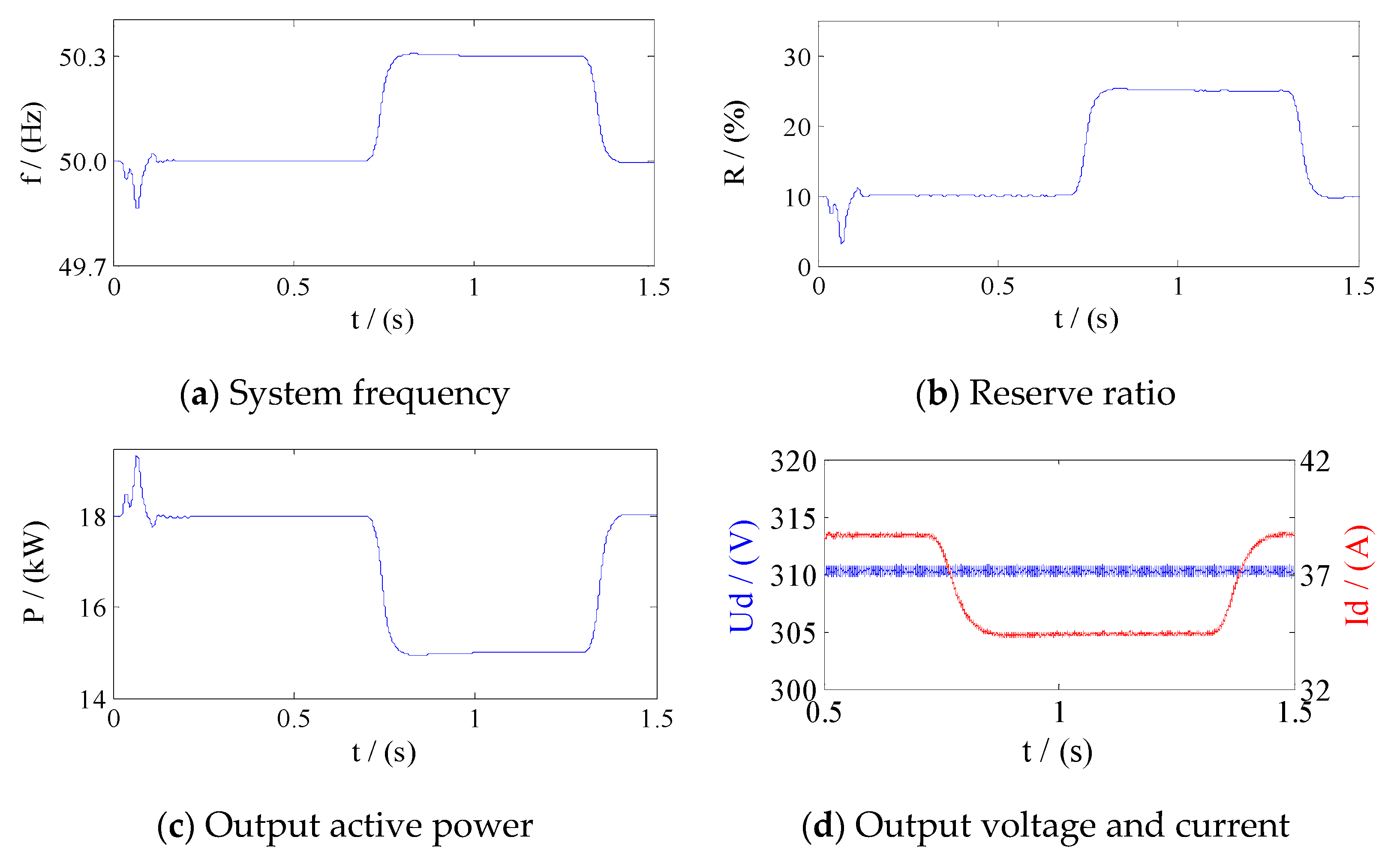
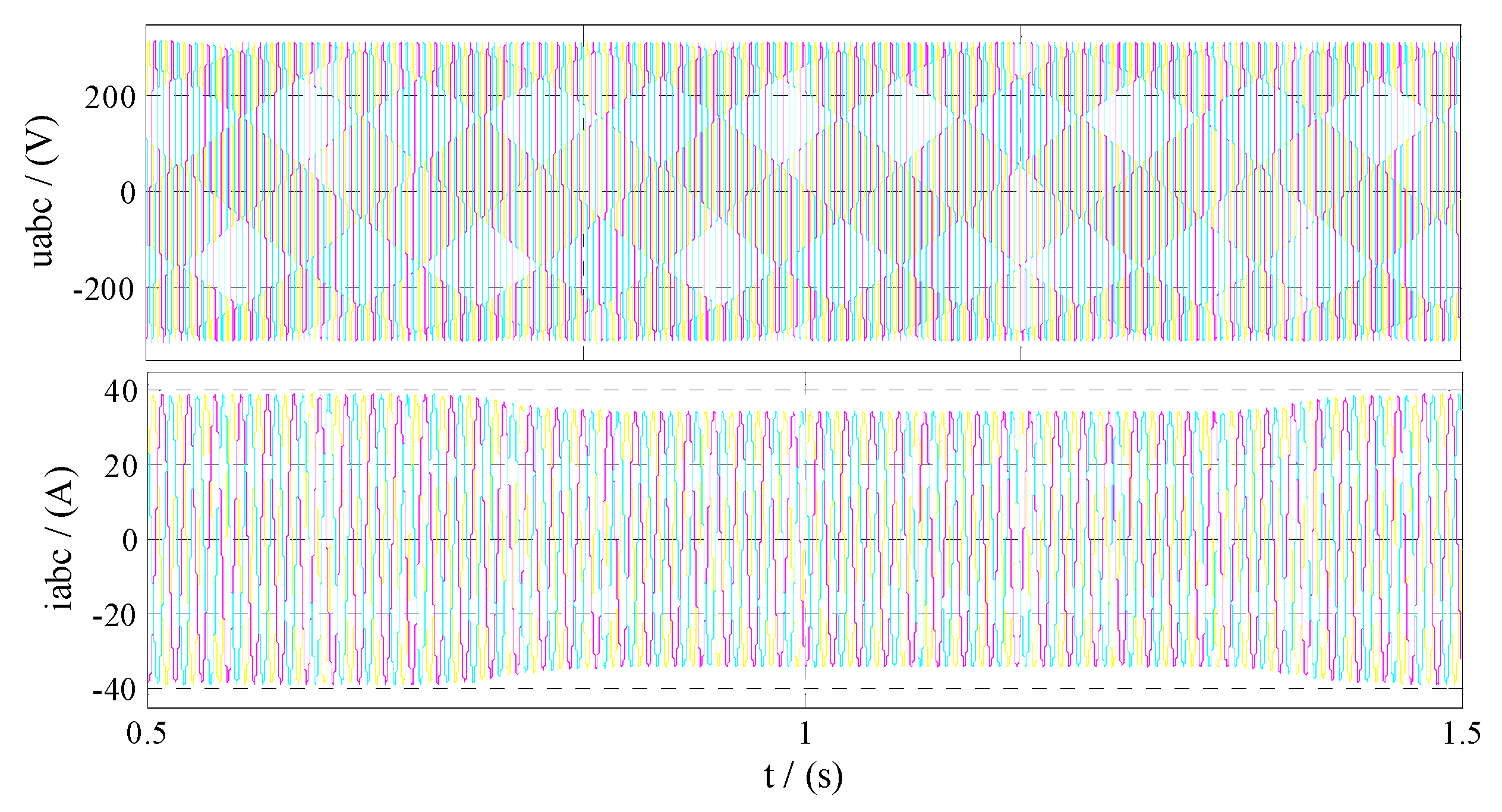
The simulation time is 1.5 s, and the system frequency does not change from 0 to 0.7 s. At 0.7 s, the power system has the problem of excess power, which leads to the sudden change of the system frequency from 50 Hz to 50.3 Hz, and it returns to normal at 1.3 s. The frequency variation of the system is shown in Figure 7a. Because of the inertia, the rise curve of the system frequency is smoother. Equation (7) shows that when the system frequency increases, the reserve power rises to 5 kW, and the reserve rate increases to 25% as calculated by Equation (8), and as shown in Figure 7b. The active power of PV output is further reduced to 15 kW, as shown in Figure 7c, and the output voltage and current of the inverter are shown in Figure 7d. The results are in agreement with those of the formulas of Equations (7) and (8). The whole response process essentially maintains power system stability by abandoning a part of PV energy.
• System Frequency Drop in a Small Range
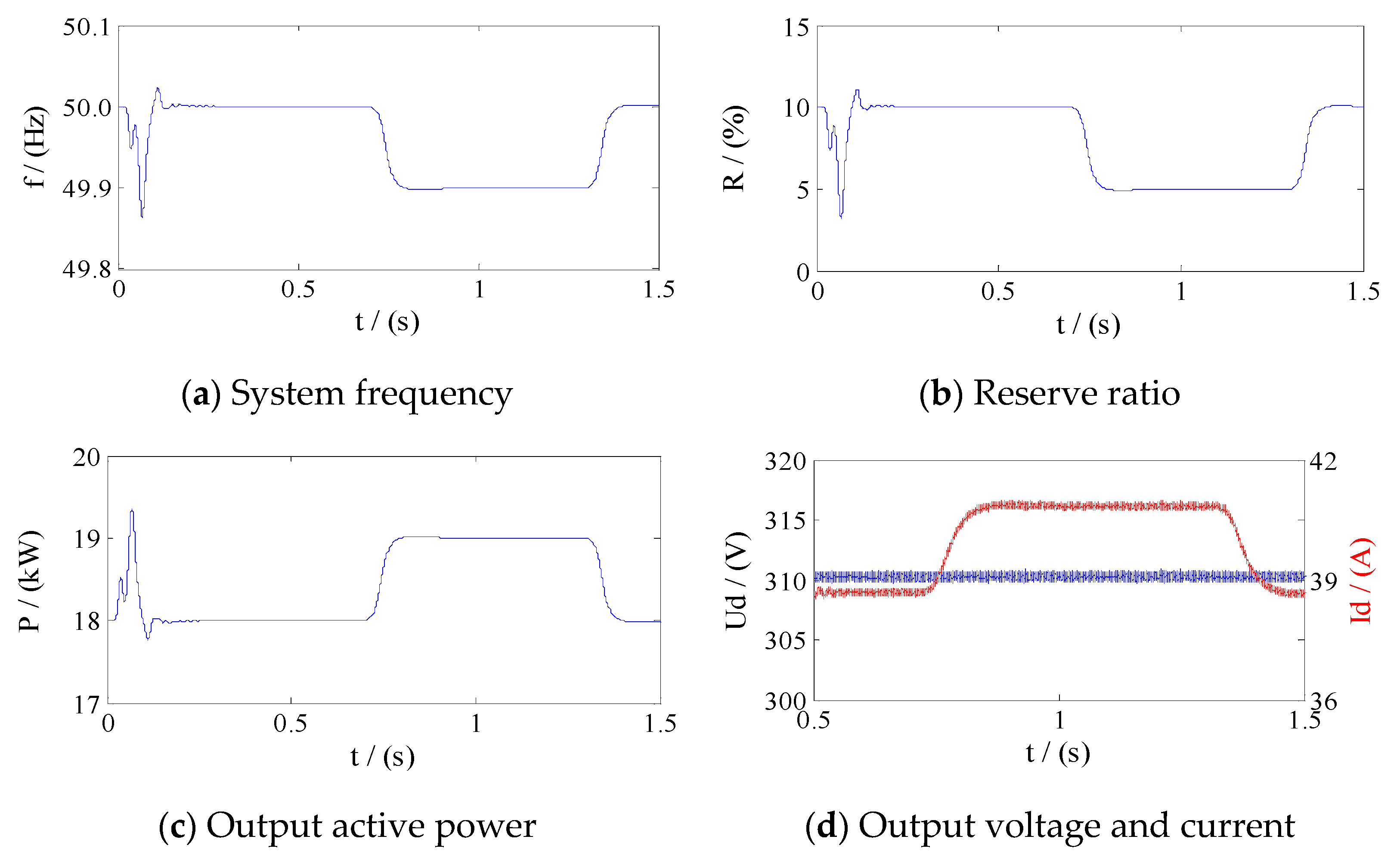
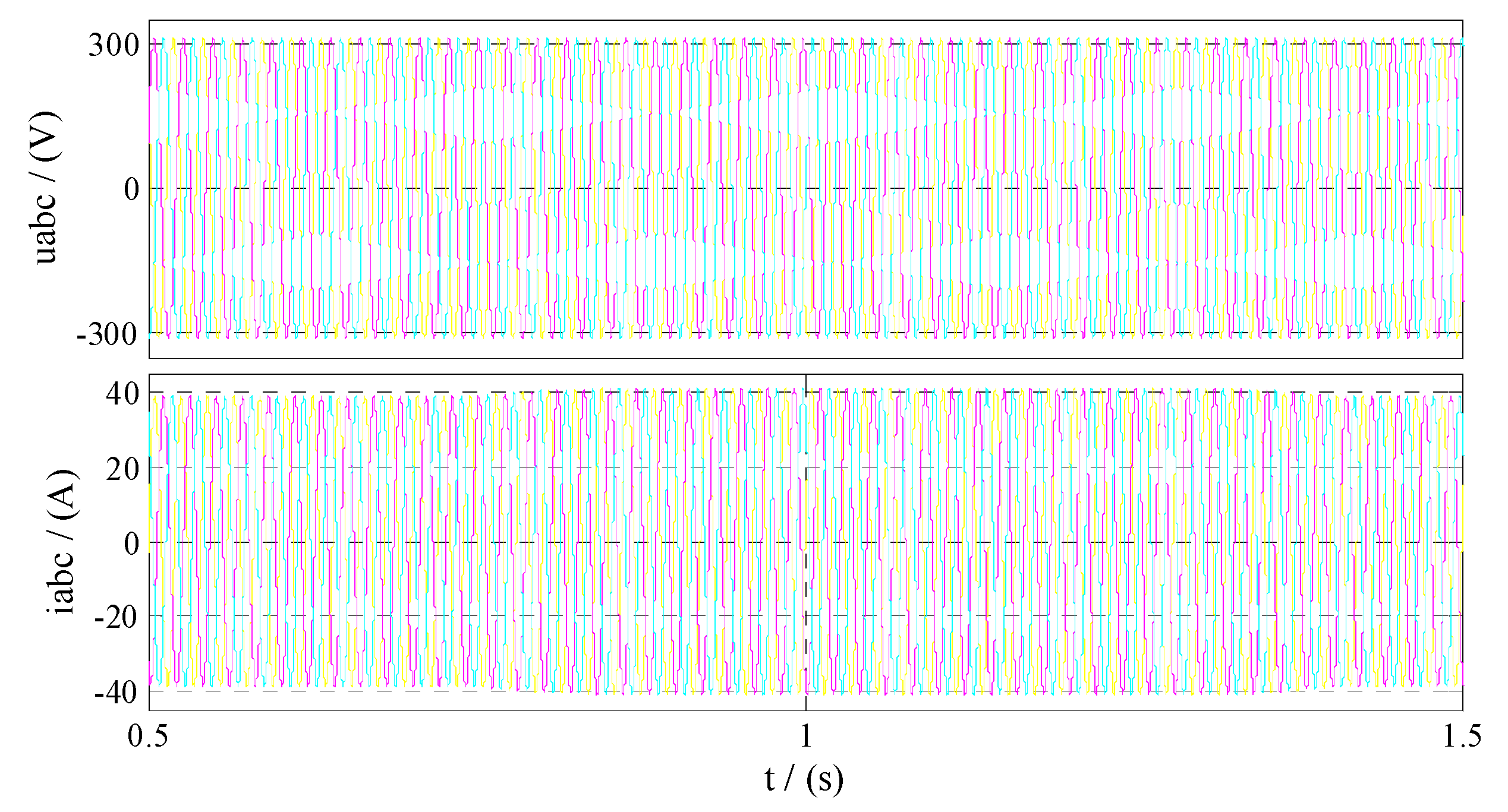
The simulation parameter setting and the initial reserved power amount are the same as above. When the system loses part of the external power due to generator failure at 0.7 s, the system frequency is reduced from 50 to 49.9 Hz, and it returns to normal at 1.3 s, as shown in Figure 8a. When the system frequency drop is detected, the PV system needs to release a part of the reserve active power. According to Equations (7) and (8), the standby rate reference value needs to be changed from 10 to 5%, as shown in Figure 8b. During the frequency drop, a part of the active power is released by the reduction of the reserve ratio to participate in the primary frequency response of the power grid, and the output power is as shown in Figure 8c, and Figure 8d shows the output voltage and current of the inverter.
• Serious Decrease of System Frequency
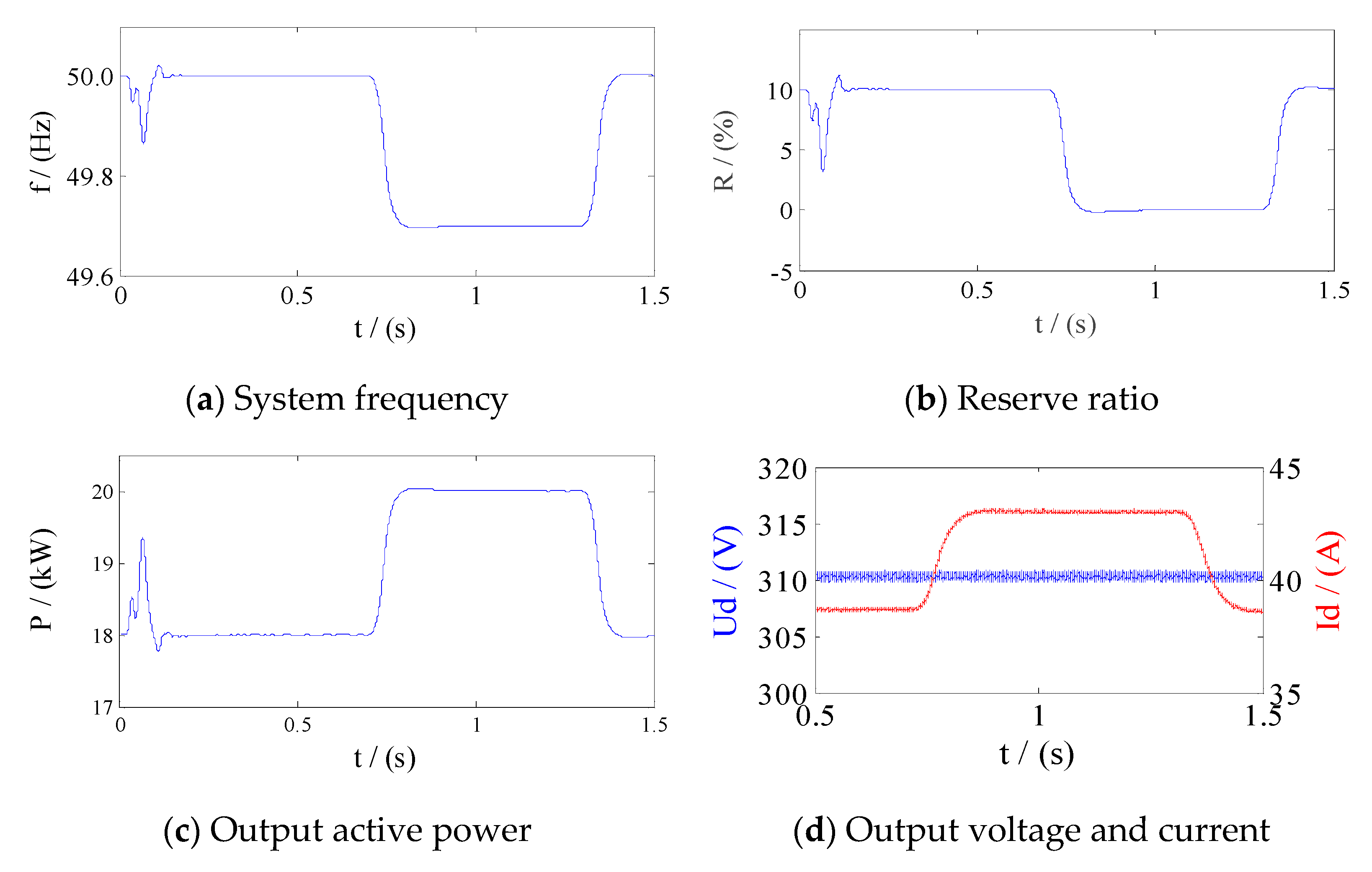
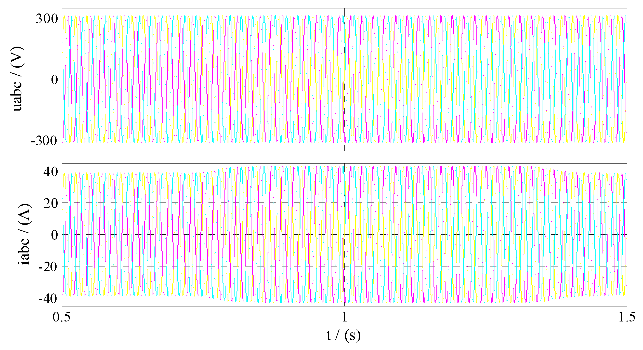
The initial parameters of the simulation are the same as above. When the large load is suddenly cut in 0.7–1.3 s, the system frequency is reduced from 50 to 49.7 Hz. According to the setting, the PV system reduces the reserve ratio and increases the active output. Due to the limited active reserve of the PV system, the frequency response will be limited. Equation (7) shows that when the frequency drops by more than 0.2 Hz, the PV system will release all reserve power. Therefore, under this condition, the PV system reserve ratio is changed from 10 to 0%, all the active reserve is released, and the grid is integrated into the grid in MPPT mode. The simulation diagram is shown in Figure 9a–d. It can be seen that the frequency modulation effect of the PV-ESSs-VSG system in reference [13] can be achieved without external ESSs, and the active power support time provided is longer.
6. Conclusions
Aiming at the problem that the traditional PV-VSG technology relies on external ESSs, which leads to a large increase in the cost of large-scale PV-PPs construction and limits its application in engineering, this paper puts forward PV-PRC-VSG technology. Boosting the converter realizes the active reserve of the PV system, power output can be adjusted to realize the independent frequency modulation of PV system, and DC/AC inverter to achieve power conversion, and reactive power control. The PV system participates in the frequency response of the power system. Through the analysis and experimental verification, the following conclusions are drawn:
- The PRC method of the PV system in this paper can work in MPPT and PRC modes in a time-sharing manner according to actual needs and does not need to switch the control strategy;
- Considering the efficient and safe operation of the inverters, it is determined that the voltage operating point in PV-PRC mode should be on the right side of , and the reserve rate should be 10% considering the abandonment of PV energy and frequency modulation ability of the participating system;
- The proposed PV-PRC-VSG control strategy can actively participate in the frequency response of the power system without additional ESSs. It also has a longer power support time, but it is also constrained by the reserve power capacity.
Author Contributions
The research method and control scheme of this paper was put forward by G.B., and H.T. was responsible for the analysis of the experimental results and the writing of the manuscript of the paper. Special thanks were given to K.D., M.M. and N.W. senior engineers of State Grid Gansu Electric Power Corporation Electric Power Research Institute for their practical engineering background and related data.
Funding
This research was supported by State Grid Corporation Science and Technology Project (5227 2217006), and National Natural Science Foundation of China (No. 51267001), and 2018 GanSu university scientific research project - innovation team.
Conflicts of Interest
The authors declare no conflict of interest.
Appendix A
Figure A1.
VSG structure in this paper.

Figure A2.
System output voltage and current when the frequency increases by 0.3 Hz.

Figure A3.
System output voltage and current when the frequency decreases by 0.1 Hz.

Figure A4.
System output voltage and current when the frequency decreases by 0.3 Hz.

References
- Zhou, X.; Lu, Z.; Liu, Y.; Chen, S. Development models and key technologies of future grid in China. Proc. CSEE 2014, 34, 4999–5008. [Google Scholar]
- Rahmann, C.; Castillo, A. Fast frequency response capability of photovoltaic power plants. The necessity of new grid requirements and definitions. Energies 2014, 7, 6306–6322. [Google Scholar] [CrossRef]
- Liu, Y.; You, S.; Tan, J.; Zhang, Y.; Liu, Y. Frequency response assessment and enhancement of the U.S. Power grids towards extra-high photovoltaic generation penetrations—An industry perspective. IEEE Trans. Power Syst. 2018, 33, 3438–3449. [Google Scholar] [CrossRef]
- Ming, D.; Sheng, W.W.; Wang, X.; Song, Y.T.; Chen, D.Z.; Sun, M. A review on the effect of large-scale PV generation on power systems. Proc. CSEE 2014, 34, 1–14. [Google Scholar]
- Eftekharnejad, S.; Vittal, V.; Heydt, G.T.; Keel, B.; Loehr, J. Impact of increased penetration of photovoltaic generation on power systems. IEEE Trans. Power Syst. 2013, 28, 893–901. [Google Scholar] [CrossRef]
- Tamimi, B.; Cañizares, C.; Bhattacharya, K. System stability impact of large-scale and distributed solar photovoltaic generation: The case of Ontario, Canada. IEEE Trans. Sustain. Energy 2013, 4, 680–688. [Google Scholar] [CrossRef]
- Koran, A.; LaBella, T.; Lai, J.S. High efficiency photovoltaic source simulator with fast response time for solar power conditioning systems evaluation. IEEE Trans. Power Electron. 2014, 29, 1285–1297. [Google Scholar] [CrossRef]
- Zhong, Q.C.; Weiss, G. Synchronverters: Inverters that mimic synchronous generators. IEEE Trans. Ind. Electron. 2011, 58, 1259–1267. [Google Scholar] [CrossRef]
- Zhong, Q.C.; Nguyen, P.L.; Ma, Z.; Sheng, W. Self-synchronized synchronverters: Inverters without a dedicated synchronization unit. IEEE Trans. Power Electron. 2014, 29, 617–630. [Google Scholar] [CrossRef]
- Alipoor, J.; Miura, Y.; Ise, T. Power system stabilization using virtual synchronous generator with alternating moment of inertia. IEEE J. Emerg. Sel. Top. Power Electron. 2015, 3, 451–458. [Google Scholar] [CrossRef]
- Kakimoto, N.; Takayama, S.; Satoh, H.; Nakamura, K. Power modulation of photovoltaic generator for frequency control of power system. IEEE Trans. Energy Convers. 2009, 24, 943–949. [Google Scholar] [CrossRef]
- Hill, C.A.; Such, M.C.; Chen, D.; Gonzalez, J.; Grady, W.M. Battery energy storage for enabling integration of distributed solar power generation. IEEE Trans. Smart Grid 2012, 3, 850–857. [Google Scholar] [CrossRef]
- Yu, G.; Yang, W.; Zhi, L.; Shi, X.; Song, P.; Yang, W.X..; Zheng, W. Engineering application effect analysis and optimization of photovoltaic virtual synchronous generator. Autom. Elect. Power Syst. 2018, 42, 149–156. [Google Scholar]
- Consulting Group of State Grid Corporation of China to Prospects of New Technologies in Power Systems. An analysis of prospects for application of large-scale energy storage technology in power systems. Autom. Elect. Power Syst. 2013, 37, 3–8. [Google Scholar]
- Xin, H.; Liu, Y.; Wang, Z.; Gan, D.; Yang, T. A new frequency regulation strategy for photovoltaic systems without energy storage. IEEE Trans. Sustain. Energy 2013, 4, 985–993. [Google Scholar] [CrossRef]
- Sangwongwanich, A.; Yang, Y.; Blaabjerg, F. A sensorless power reserve control strategy for two-stage grid-connected PV systems. IEEE Trans. Power Electron. 2017, 32, 8559–8569. [Google Scholar] [CrossRef]
- Sangwongwanich, A.; Yang, Y.; Blaabjerg, F.; Sera, D. Delta power control strategy for multistring grid-connected PV inverters. IEEE Trans. Ind. Appl. 2017, 53, 3862–3870. [Google Scholar] [CrossRef]
- Batzelis, E.I.; Kampitsis, G.E.; Papathanassiou, S.A. Power reserves control for PV systems with real-time MPP estimation via curve fitting. IEEE Trans. Sustain. Energy 2017, 8, 1269–1280. [Google Scholar] [CrossRef]
- Batzelis, E.I.; Papathanassiou, S.; Pal, B.C. PV system control to provide active power reserves under partial shading conditions. IEEE Trans. Power Electron. 2018, 33, 9163–9175. [Google Scholar] [CrossRef]
- Li, X.; Wen, H.; Zhu, Y.; Jiang, L.; Hu, Y.; Xiao, W. A novel sensorless photovoltaic power reserve control with simple real-time MPP estimation. IEEE Trans. Power Electron. 2019, 34, 7521–7531. [Google Scholar] [CrossRef]
- Hoke, A.; Maksimović, D. Active power control of photovoltaic power systems. In Proceedings of the 2013 1st IEEE Conference on Technologies for Sustainability (SusTech), Portland, OR, USA, 1–2 August 2013; pp. 70–77. [Google Scholar]
- Hoke, A.F.; Shirazi, M.; Chakraborty, S.; Muljadi, E.; Maksimovic, D. Rapid active power control of photovoltaic systems for grid frequency support. IEEE J. Emerg. Sel. Top. Power Electron. 2017, 5, 1154–1163. [Google Scholar] [CrossRef]
- Bevrani, H. Virtual synchronous generators: A survey and new perspectives. Int. J. Electr. Power Energy Syst. 2014, 54, 244–254. [Google Scholar] [CrossRef]
Figure 1.
Principle and embodiment of the virtual synchronous generator (VSG).

Figure 2.
PV-energy storage systems (ESSs)-VSG output wave.

Figure 3.
PV-PRC voltage operating point diagram.

Figure 4.
PV-PRC block diagram.

Figure 5.
Principle of PRC-VSG implementation.

Figure 6.
PV-PRC mode simulation waveform.

Figure 7.
System output waveform when frequency increases by 0.3 Hz.

Figure 8.
System output waveform when frequency decreases by 0.1 Hz.

Figure 9.
System output waveform when frequency decreases by 0.3 Hz.


Table 1.
Comparison of the control functions of the converter in the two-stage grid-connected photovoltaic virtual (PV) system.
Table 1.
Comparison of the control functions of the converter in the two-stage grid-connected photovoltaic virtual (PV) system.
| Converter Type | DC/DC Converter | DC/AC Converter |
|---|---|---|
| Main Functions | Maximum Power Point Tracking (MPPT) | Power Conversion Control |
| Power Reserve Control | DC-Link Voltage Control | |
| Active Power Control | Reactive Power Control | |
| Current Control |
Table 2.
PV module parameter data sheet.
| 36.0 | 8.96 | 29.4 | 8.0 | −0.37 | 0.006 |
Table 3.
Simulation parameters.
| Parameter | Selection | Parameter | Selection |
|---|---|---|---|
| PV module | JLS60P240W | R | 10%Pmpp |
| Ns × Np | 12 × 7 | Pmpp | 20 kW |
| Pdeload | 18 kW | Dp | 10,000/2 pi |
© 2019 by the authors. Licensee MDPI, Basel, Switzerland. This article is an open access article distributed under the terms and conditions of the Creative Commons Attribution (CC BY) license (http://creativecommons.org/licenses/by/4.0/).
Share and Cite
MDPI and ACS Style
Bao, G.; Tan, H.; Ding, K.; Ma, M.; Wang, N. A Novel Photovoltaic Virtual Synchronous Generator Control Technology Without Energy Storage Systems. Energies 2019, 12, 2240. https://doi.org/10.3390/en12122240
AMA Style
Bao G, Tan H, Ding K, Ma M, Wang N. A Novel Photovoltaic Virtual Synchronous Generator Control Technology Without Energy Storage Systems. Energies. 2019; 12(12):2240. https://doi.org/10.3390/en12122240
Chicago/Turabian StyleBao, Guangqing, Hongtao Tan, Kun Ding, Ming Ma, and Ningbo Wang. 2019. "A Novel Photovoltaic Virtual Synchronous Generator Control Technology Without Energy Storage Systems" Energies 12, no. 12: 2240. https://doi.org/10.3390/en12122240
Note that from the first issue of 2016, this journal uses article numbers instead of page numbers. See further details here.