Non-Linear Control for Variable Resistive Bridge Type Fault Current Limiter in AC-DC Systems


1
Department of Electrical Engineering, King Fahd University of Petroleum & Minerals, Dhahran 31261, Saudi Arabia
2
Department of Electrical & Electronic Engineering, International Islamic University Chittagong, Chittagong 4318, Bangladesh
*
Author to whom correspondence should be addressed.
Energies 2019, 12(4), 713; https://doi.org/10.3390/en12040713
Submission received: 15 January 2019
/
Revised: 7 February 2019
/
Accepted: 10 February 2019
/
Published: 22 February 2019
(This article belongs to the Section F: Electrical Engineering)
Abstract
:This paper proposes a non-linear control-based variable resistive bridge type fault current limiter (VR-BFCL) as a prospective solution to ease the effect of disturbances on voltage source converter-based high voltage DC (VSC-HVDC) systems. A non-linear controller for VR-BFCL has been developed to insert a variable optimum resistance during the inception of system disturbances in order to limit the fault current. The non-linear controller takes the amount of DC link voltage deviation as its input and provides variable duty to generate a variable effective resistance during faults. The VSC-HVDC system’s real and reactive power controllers have been developed based on a current control loop where direct axis and quadrature axis currents are used to control the active and reactive power, respectively. The efficacy of the proposed non-linear control-based VR-BFCL solution has been proved with balanced as well as unbalanced faults. The results confirm that the oscillations in active power and DC link voltage have been significantly reduced by limiting the fault current through the insertion of an optimum effective resistance with the proposed control technique. The real time digital simulator (RTDS) has been used to implement the proposed approach. The performance of the proposed non-linear control based VR-BFCL is compared with that of traditional fixed duty control.
1. Introduction
High voltage direct current (HVDC) has evolved as an optimum solution for renewable energy integration and long-distance power transmission, especially voltage source converter-based HVDC (VSC-HVDC). Compared to traditional line commutated converter HVDC (LCC-HVDC), VSC-HVDC system have several potential benefits, for instance, independent control of active and reactive power, high power quality, lower losses and less insulation material for the DC cables [1,2,3]. Additionally, nowadays, different problems faced by power networks such as network congestion and grid re-enforcements are resolved by using VSC-HVDC [4,5]. Mainly two-level and multi-level VSC topologies are presented in the literature [6,7] for VSC-HVDC transmission system.
However, despite several potential benefits, VSC-HVDC systems are more defenceless against AC/DC faults than LCC-HVDC systems. Upon the occurrence of short circuit faults, the level of fault current surges tenfold within several milliseconds feeding very high fault currents into the DC cables through the freewheel diode which may cause severe damage to the voltage source converters [8,9,10,11]. Currently, analysis and isolation of DC faults on VSC-based DC systems has attracted the interest of numerous researchers [12,13,14]. Since large capacity DC circuit breaker technology and its engineering application is not yet mature, a novel DC fault handling capability for a modular multi-level (MMC)-based system is presented in [12]. The presented method adopts damping modules to accelerate DC fault isolation and avoid maloperation of AC system protection. Earthed and unearthed DC fault detection and protection methodology for DC systems is presented with a back propagation neural network [14].
A prospective solution to the fault problems of VSC-HVDC systems is to employ fault current limiters [15]. During the response time of a circuit breaker, a fault current limiter can suppress the large fault current in VSC-HVDC systems. Thus, fault current limiters can evidently mitigate the current interruption stress on circuit breakers and avoid possible serious damage to the power electronic converters. Superconducting [16,17,18,19,20,21] and non-superconducting [22,23,24,25,26,27,28,29] fault current limiters (FCLs) have been widely applied in power systems to protect them against high currents as well as improve transient stability.
A DC reactor type superconducting FCL has been presented [30] to limit the fault current which has high implementation and maintenance costs. This structure also has a resistor to reduce the current rating of the superconducting coil. However, this resistance cannot be varied to control the fault current level. In [29], a similar type of FCL has been introduced with a non-superconducting DC coil. This structure is more practical and keeps the fault current level within the pre-specified value range better than the one presented in [30]; however, it has a considerable voltage drop in the large non-superconducting coil.
To date, VSC-HVDC system stability has been examined with the implementation of different categories of superconducting FCLs (SFCLs) [1,9,31,32]. However, superconducting fault current limiters have several drawbacks such as big size, heavy weight and cost, magnetic field interference with nearby sensitive devices, higher leakage and circulating currents, long recovery time, and loss in stand-by mode [33,34,35,36,37,38,39,40] compared to non-superconducting fault current limiters. Non-superconducting variable resistive bridge type fault current limiters (VR-BFCLs) could restrict the fault current as well as improve transient stability with low cost, loss and voltage drop [24,28,41,42]. However, this new non-superconducting low cost VR-BFCL technology has not been examined as yet in VSC-HVDC systems for fault current reduction as well dynamic performance improvement. Thus, VR-BFCL presents a potential solution for improving the FRT operation of VSC-HVDC with minimal cost.
Against this background, a variable resistive bridge type fault current limiter (VR-BFCL) has been proposed in this work to enhance VSC-HVDC system FRT capability. A simple non-linear control has been proposed to control VR-BFCL. The advantage of the proposed non-linear control is two-fold in that it is superior to traditional fixed duty control and less complicated as well as easy to implement. In this work, non-linear control based VR-BFCL is proposed and the performance of the proposed strategy is compared with conventional fixed duty-based control approach. Real time implementation of the system and associated controllers has been conducted with a real time digital simulator (RTDS) device.
2. Variable Resistive Bridge Type Fault Current Limiter
In this study, non-linear control-based VR-BFCL has been proposed to resolve the fault issues in VSC-HVDC systems. Its construction, operating principles and the proposed non-linear control method are described in the subsections that follow.
2.1. VRBFCL Structrue and Operation
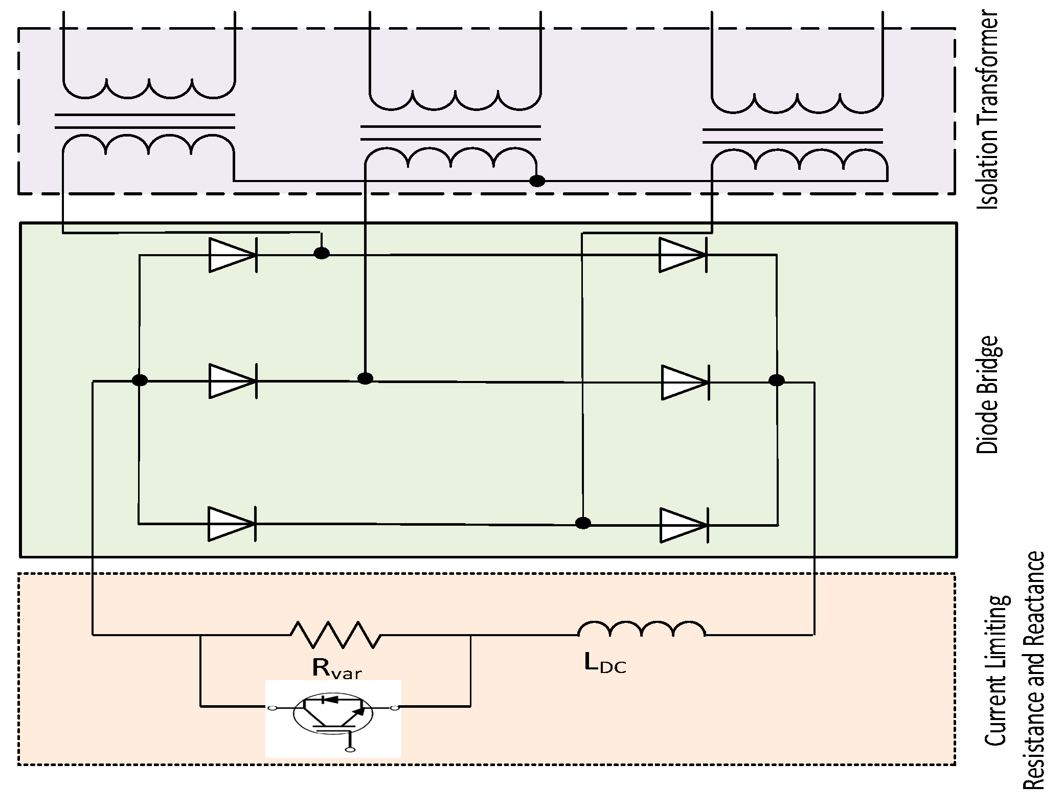
VR-BFCL is composed of an isolation transformer, a diode bridge, and series connected resistance and reactance in the DC side of the diode bridge [41,42,43,44] as shown in Figure 1. An IGBT switch is connected in parallel with the resistance, the main current limiting part of VR-BFCL. IGBT switch is kept turned on during normal operation of the system without any fault and hence evacuating resistance is bypassed. In this operating condition, LDC acts like short circuit as it gains maximum charge corresponding to the maximum value of the line current. Eventually, VR-BFCL has approximately no effect on normal operation of the power system. The main purpose of adding LDC in series with resistance is to protect drastic increase of current and hence to provide protection of IGBT switch against large di/dt.
The DC side voltage of the VR-BFCL is given by the following equation [41]:
where a the isolation transformer turns ratio and Vm is the peak voltage in the primary side of the isolation transformer. The effective resistance appeared in the DC side of the bridge can be made adaptable by applying the proper control signal to the IGBT gate as follows:
where RDC and D are the effective DC resistance and duty ratio, respectively. The concept of equal power in the AC and DC sides of bridge is employed in order to find the effective resistance appearing in the AC side by neglecting the power loss in isolation transformer, bridge rectifier and IGBT switch as follows [41]:
This gives the following effective AC resistance:
This effective resistance appears in series with the line during system faults to reduce the severe fault current and eventually improvement of system FRT capability as well as dynamic stability is observed. In this study, a non-linear controller is proposed to generate variable duty cycle during the inception of severe faults in order to insert dynamic effective resistance for regulating fault current and augmenting the transient stability of AC/DC systems.
2.2. Non-linear Control of VRBFCL
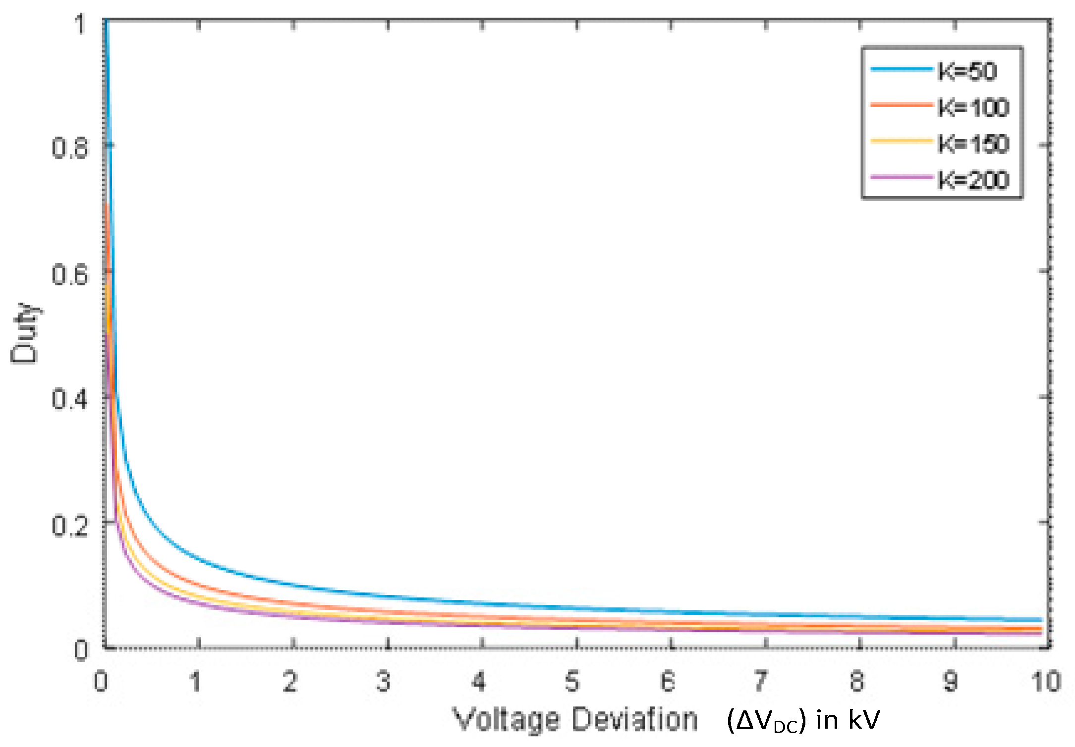
Since the power system is highly non-linear, a nonlinear controller is proposed in this work to control VR-BFCL. The control block takes the deviation of reference DC link voltage (VDCref) and measured DC link voltage (VDCmes) of the HVDC link. As the HVDC system stability is mainly affected by the control action of the DC voltage control loop [45,46,47,48,49], the non-linear controller takes the amount of DC link voltage deviation as its input and provides variable duty (D) to emulate variable effective resistance during fault governed by the following non-linear equation:
where K is the gain whose optimum value is to be determined. This non-linear equation is proposed to generate variable duty depending on the total DC link voltage deviation. Duty (D) versus voltage deviation is plotted for different values of gain (K) as shown in Figure 2.
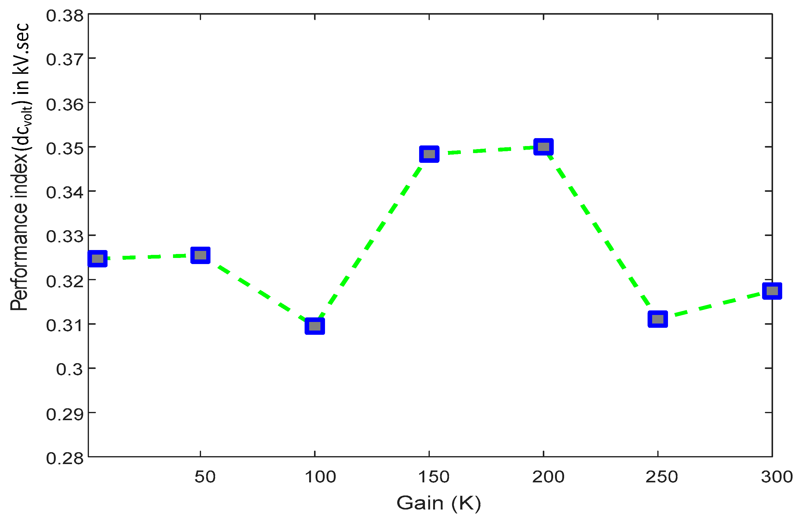
In order to determine the optimum value of the gain (K), different types of faults with different intensities have been applied in the VSC-HVDC system. It was found that K = 100 gives better performance during severe faults. This is evident from Figure 3. The performance index value for voltage deviation defined as is plotted for different values of gain (K) in Figure 3. Here, T is the transient period after the application of fault. A lower value of the index parameter indicates better system performance since it the measure of deviation of the DC link voltage. It is evident from the Figure 3 that there is an optimal value of the gain where the performance index has its optimal (lowest) value. In this study, K = 100 gives the better performance of the system during severe faults and any higher gain values give overcompensation whereas lower values provide insufficient compensation.
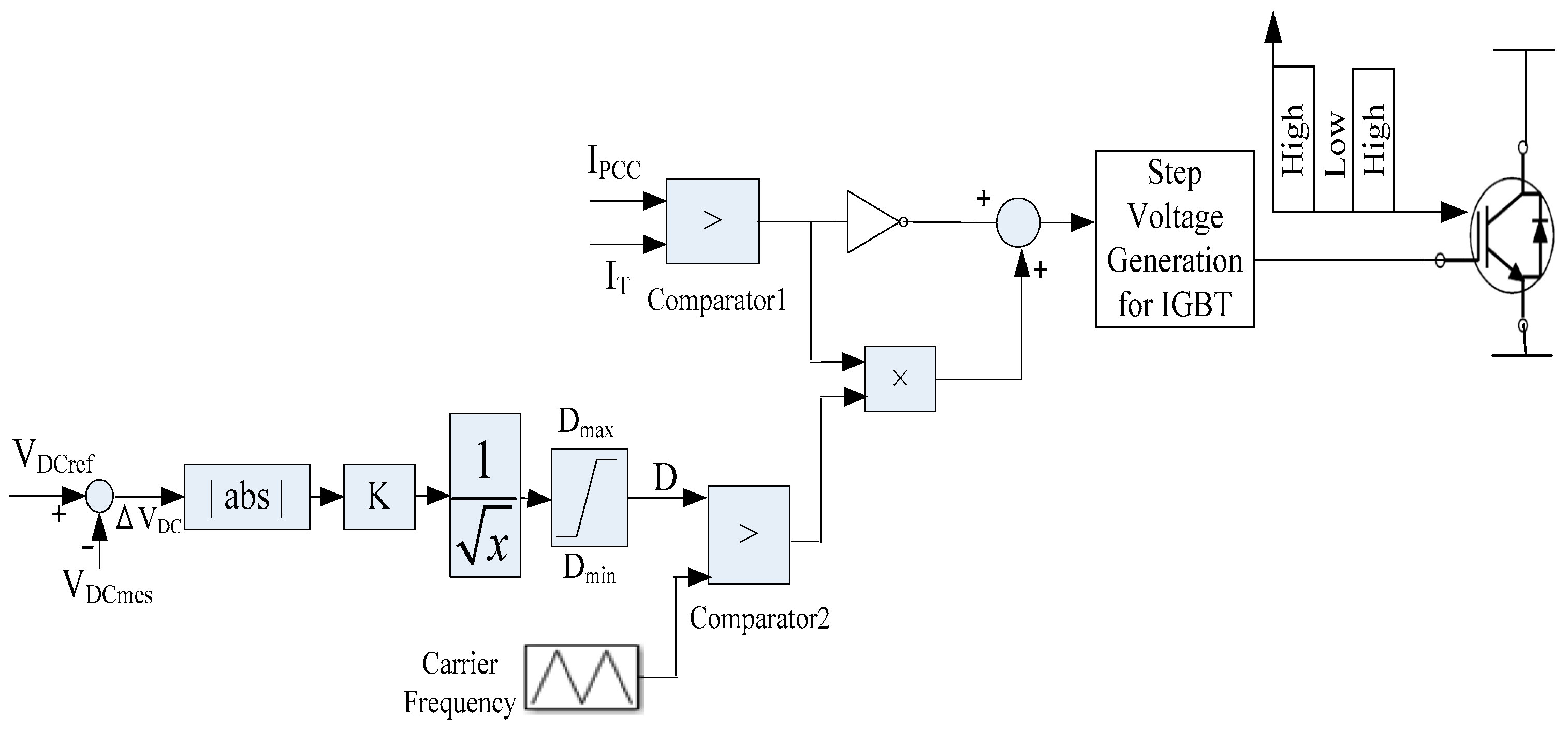
It is worth mentioning that other nonlinear functions such as exponential, quadratic, cubic, and logarithmic were tried. However, those functions all failed to provide better system performance. Detection of faults in AC/DC systems could be achieved by sensing voltage sag or overcurrent at the point of common coupling (PCC) [50]. Overcurrent at the PCC has been used in this study to detect faults for the proposed non-linear controller as shown in Figure 4.
Measured PCC current (IPCC) is compared with a predefined threshold current (IT). During normal operation when IPCC is lower than the IT, the output of Comparator1 becomes low. Thus, output of the summation block is high during normal operating conditions of the system. Consequently, the output of the step voltage generation block becomes high to keep IGBT turned on. Therefore, the evacuating resistance is bypassed and VR-BFCL has a negligible impact on system under these conditions. However, during grid faults IPCC goes on increasing and becomes higher than IT, and as a result the Comparator1 output becomes high, so the low and a high voltage signals are provided by the block of step voltage generation to turn on and turn off IGBT in dynamic fashion for providing varying compensation depending on the duty (D) provided by the non-linear equation during system disturbances. Another noteworthy features of this work is that the proposed non-linear controller performance is compared with fixed duty control [41] where a fixed duty is applied corresponding to the average value of the D during a severe disturbance.
3. System Modelling and Controller Design
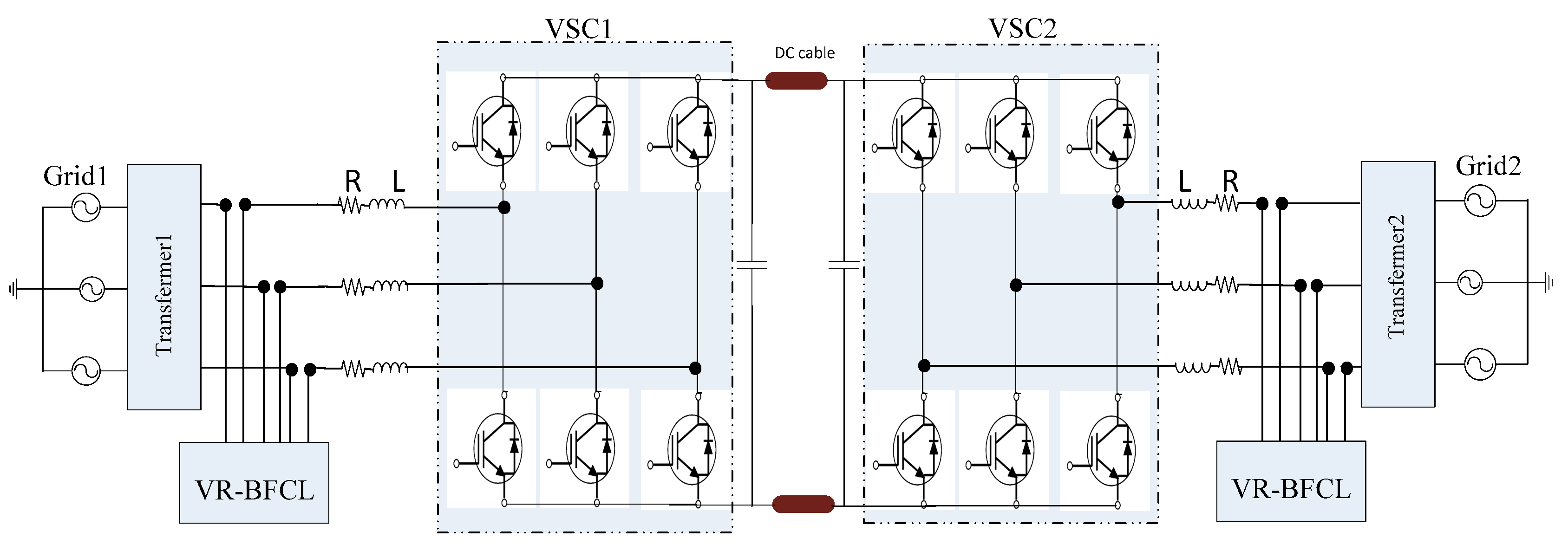
For fault ride through (FRT) capability and transient stability analysis, AC/DC system as presented in Figure 5 is demonstrated in this research work.
Power flow is bidirectional for the VSC-HVDC system depending on the reference power command of one of the VSCs in two terminal topology. Proper operation of the system mainly depends on the control of DC link voltage to a specified value. In two terminal topology, one VSC employs a double loop control strategy in which the outer controller controls the DC voltage and the inner current controller regulates the active power transfer between two grids. following subsections present in detail the proposed non-linear control technique with VR-BFCL.
3.1. Control of VSC1
The amount of active power flow between two grids is regulated by VSC1. Additionally, reactive power interchange between grid and point of common coupling (PCC) can be controlled by VSC1 in order to control AC voltage at the PCC. Now, direct axis and quadrature axis components of voltage and current can be used to control active and reactive power as follows as per instantaneous power theory:
Phase locked loop (PLL) is employed to measure grid angle and synchronize VSC with grid in such a way that quadrature axis voltage () is zero. Thus, we get following equations from the above two equations:
So, control of active and reactive power is achieved by simply controlling the direct axis and quadrature axis current, respectively, as below:
Now, using the a-b-c to d-q transformation technique the following first order differential equations and converter equations are obtained:
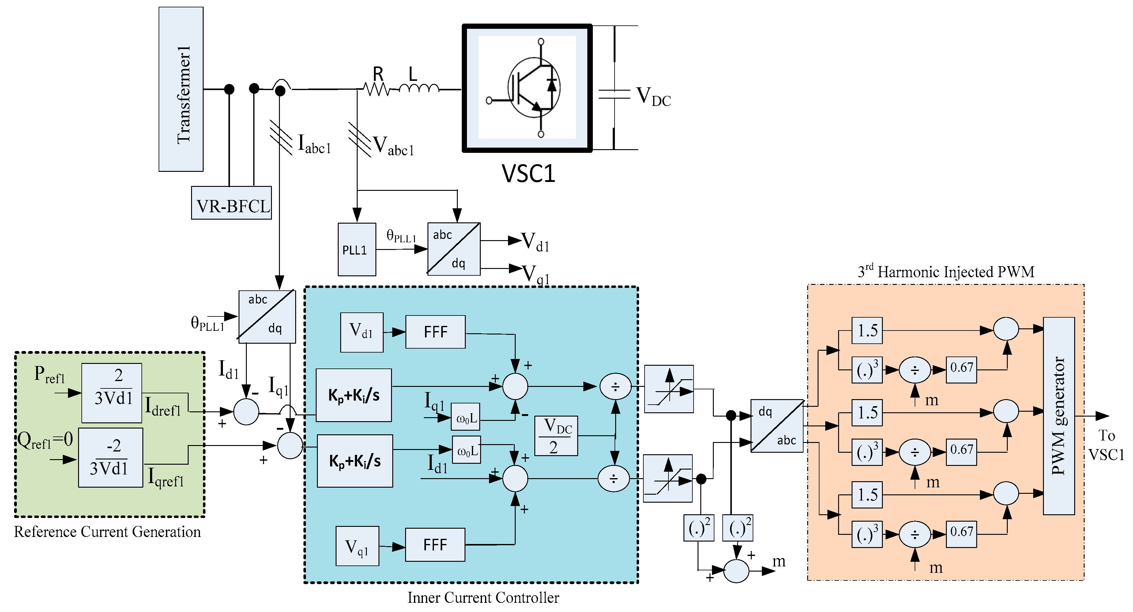
Finally, the VSC1 controller is developed using this equation set and adopting the third harmonic injected pulse width modulation (PWM) method for controlling the active and reactive power as shown in Figure 6.
As shown in Figure 6 inner current controllers control the active and reactive power controlling the corresponding d-axis and q-axis currents, respectively. Both the d-axis and q-axis currents are controller by proportional integral (PI) controllers. Controller parameters for the inner PIs are tuned by using the pole-zero cancellation technique. Implementation of a feed-forward filter (FFF) scheme removes undesirable start-up transients in the VSC. The third harmonic injected PWM method is adopted in this study as the required minimum DC bus voltage level is lower than classical PWM generation which, in turn, increases system stability in the worst case scenario [51]. In the third harmonic injected PWM technique, the squares of the d-axis and q-axis signals are added together to generate the modulating signal (m).
3.2. Control of VSC2
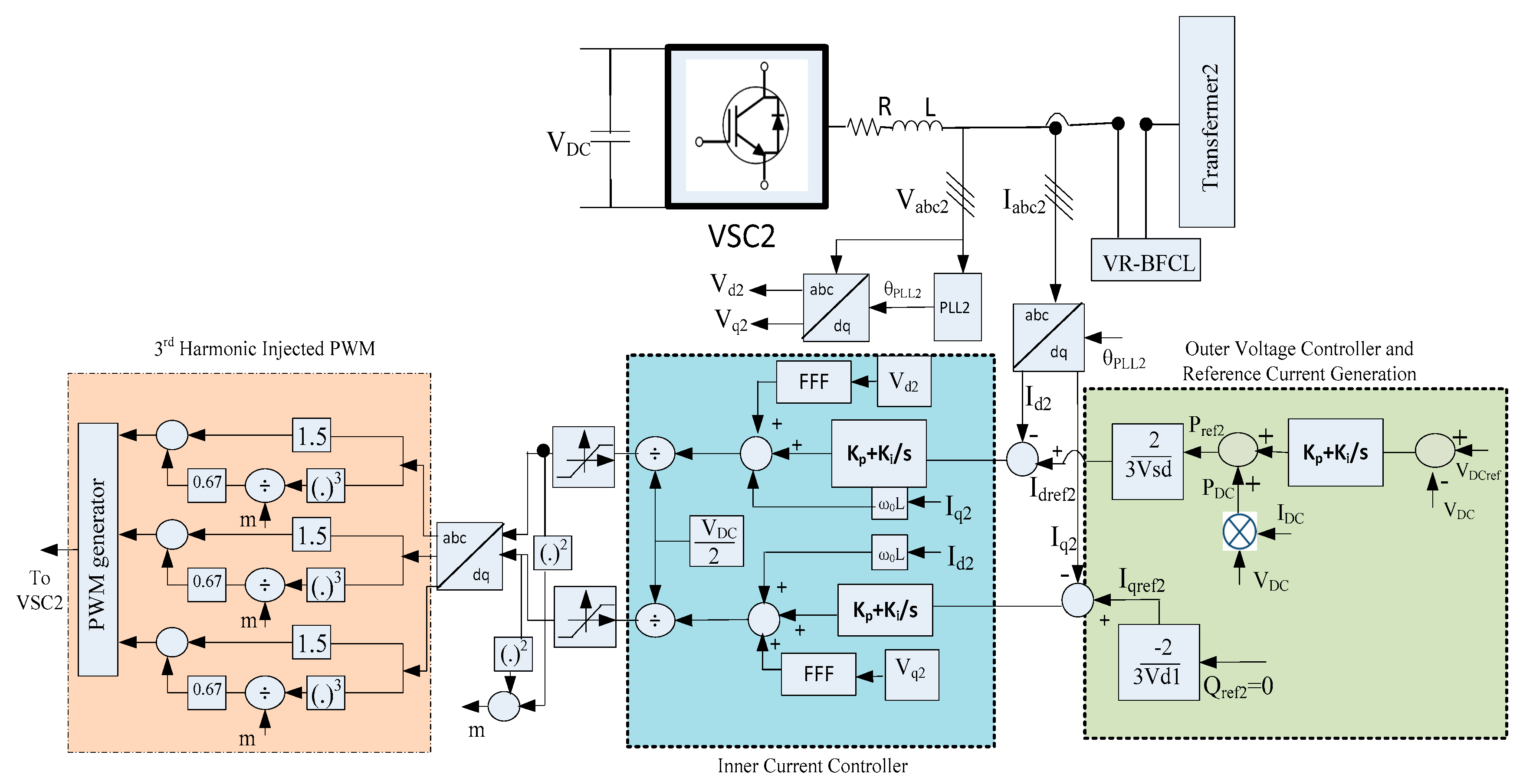
Control performance of the outer DC link voltage controller directly affects the stability of the system [45]. The VSC2 controller employs double control loop: an outer loop to control the DC link voltage and an inner loop to control the active and reactive power. The inner control loop for VSC2 is similar to the current control loop of VSC1 represented in Figure 7. The main difference is that the reference active power (Pref2) for VSC2 is delivered by the outer DC voltage regulator as shown in Figure 7.
In the outer voltage controller, the error between the measured DC voltage (VDCmes) and reference DC voltage (VDCref) is processed by a proportional integral (PI) controller. The outer PI parameters are obtained by employing the symmetrical optimum method [52]. The output of the outer PI is added to the amount of active power transferred from grid1 to grid2 for the active reference power generation of VSC2. Then, the d-axis reference current is generated and processed by the inner current control loop.
4. Results and Discussion
Both symmetrical and unsymmetrical faults have been applied in the system without FCL, with fixed duty control and with the proposed non-liner control of VR-BFCL. The system data and results are presented in the following subsections.
4.1. RTDS Implementation
The effectiveness of the proposed non-liner duty based control technique of VR-BFCL is evaluated by implementing the test system of Figure 5 and the associated controller as proposed in Figure 6 and Figure 7 in a real time environment using a real time digital simulator (RTDS). Furthermore, the non-linear controller is equated with fixed duty control to show the improvement of system performance in limiting fault current. Details of the VSC-HVDC system and controller data are listed in Table 1.
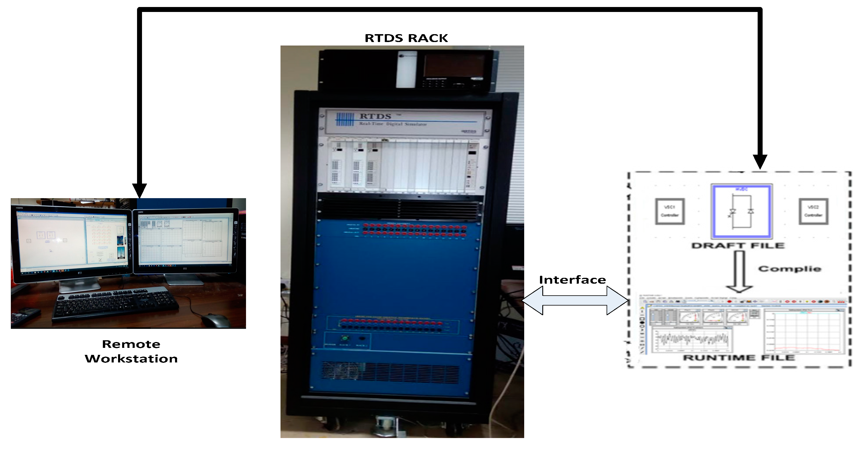
RTDS is a completely digital power system simulator working in real time. It comes with custom hardware with a high speed processor and software named RSCAD. The RTDS platform has been widely recognized by most of the electrical utilities, research institutes, protection equipment manufacturers, and educational institutions for developing and testing of power system equipment [53]. The RTDS rack is connected to the workspace computer with a network hub as shown in Figure 8. The AC/DC system and all controllers are developed in the RSCAD software and compiled in the workspace computer. After successful compilation, codes are downloaded in the RTDS hardware to run the system in real time and observe the system behavior. Detailed RTDS implementation results are presented and discussed below.
4.2. Simulation Considerations
At the start, both the VSCs are disconnected from the grids and the DC link capacitors are discharged. When the capacitors are fully discharged, VSCs are connected to the grids through the interface reactor and resistors. As a result, capacitors are now gradually charged and reach a steady state value. Then the DC link reference voltage is step changed to 35 kV and all the controllers are unblocked, so the outer DC link voltage controllers of VSC2 regulate the DC link voltage to the reference value. In the next stage, the reference power of VSC1 is changed to 20 MW in order to transfer this amount of power from grid1 to grid2. At this level, the system is ready to apply different faults and observe the improvement of system transient response with the proposed variable duty based control of VR-BFCL. Different faults are applied for six cycles and the following three conditions are evaluated:
- (i)
- without FCL
- (ii)
- with fixed duty controller VR-BFCL
- (iii)
- with proposed non-linear controller VR-BFCL
4.3. Symmetrical Fault Application
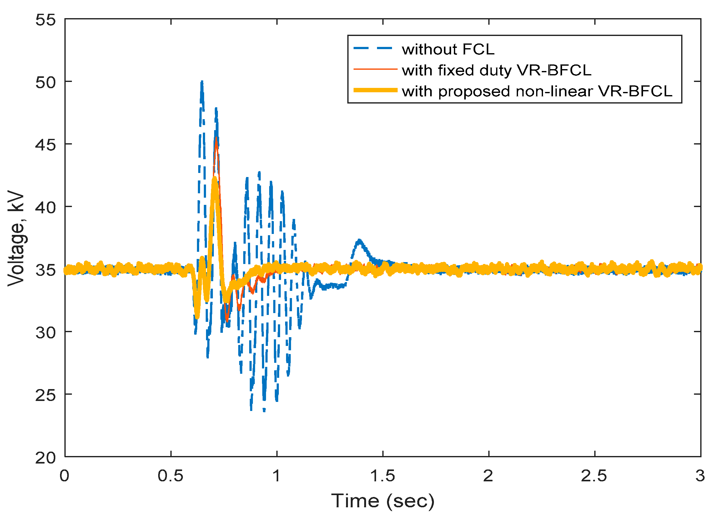
Figure 9 demonstrates the dynamic performance improvement of the VSC-HVDC system with the proposed non-linear control-based VR-BFCL for a symmetrical three-phase fault applied in grid1. The DC link voltage varies from 23.56 kV to 50.05 kV without any supplementary controller. This higher voltage fluctuation is slightly reduced with the fixed duty controller-based VR-BFCL which corresponds to a 45.76% voltage fluctuation reduction. However, the proposed non-linear control-based VR-BFCL suppresses voltage fluctuation greatly reducing the voltage variation by 62.26%. Furthermore, the settling time is significantly reduced with the proposed control technique to only 0.906 s. whereas it takes 1.04 s with the fixed duty controller and 1.669 s without any FCL.
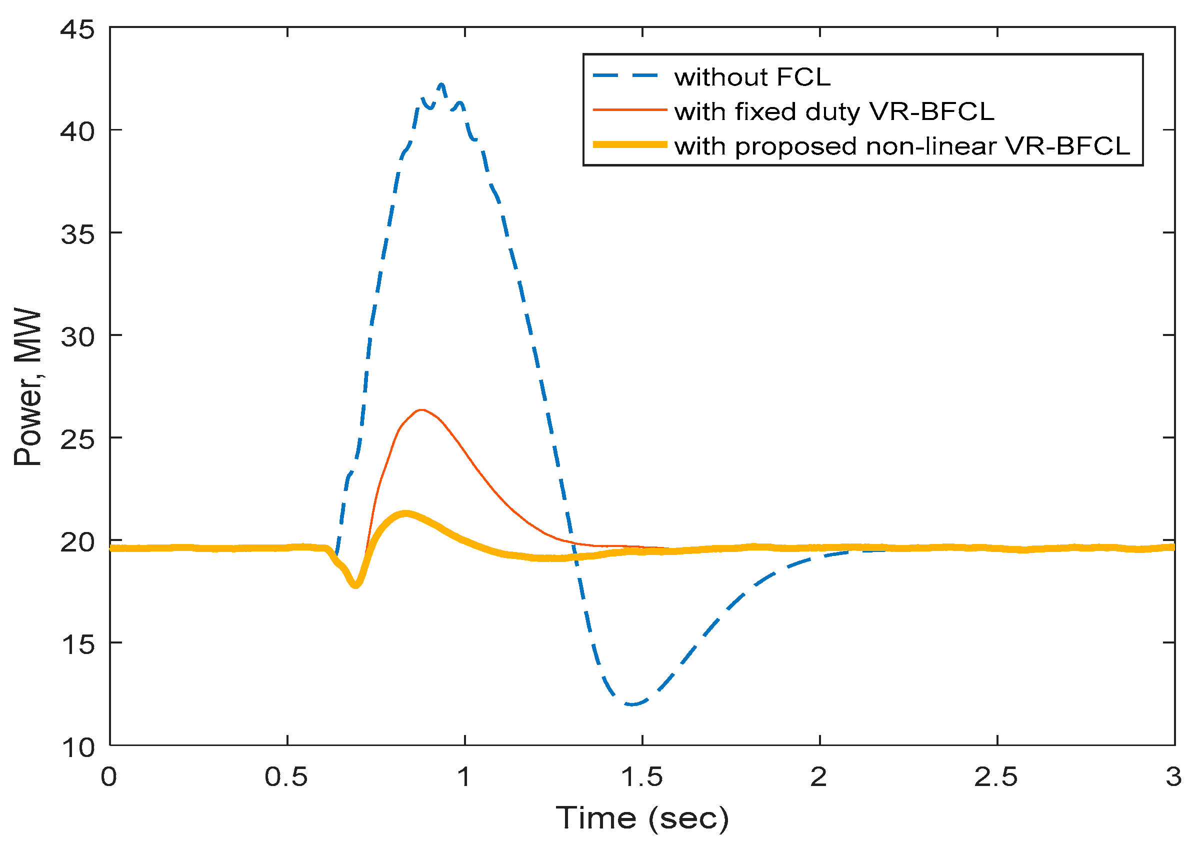
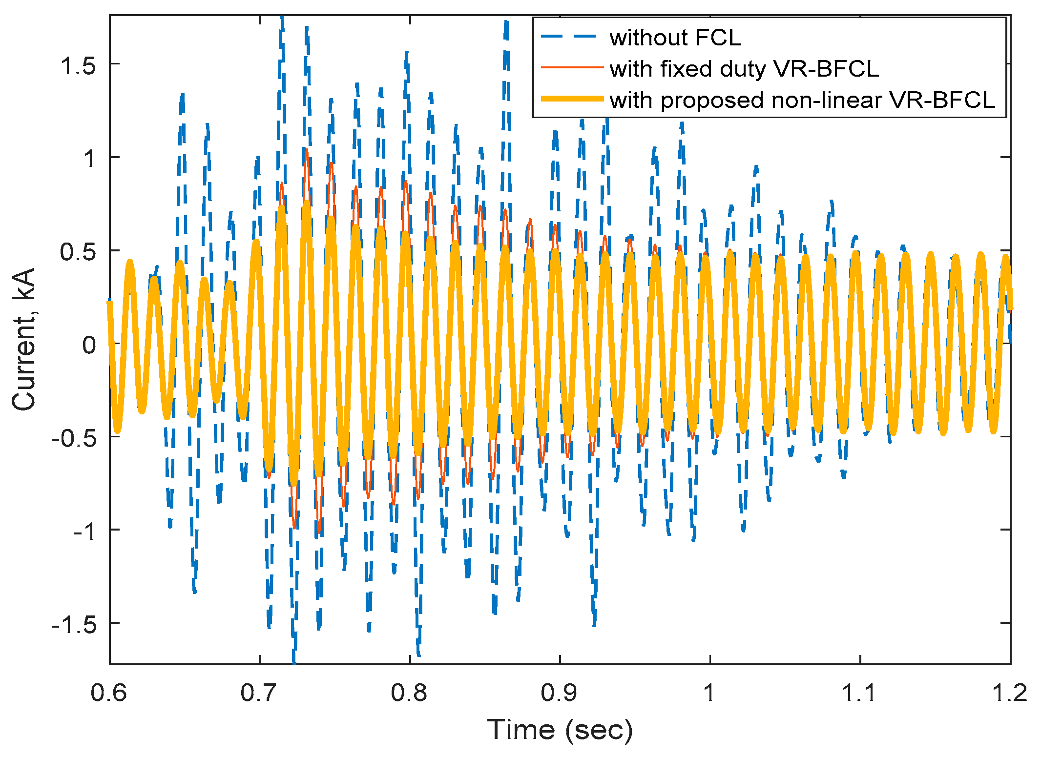
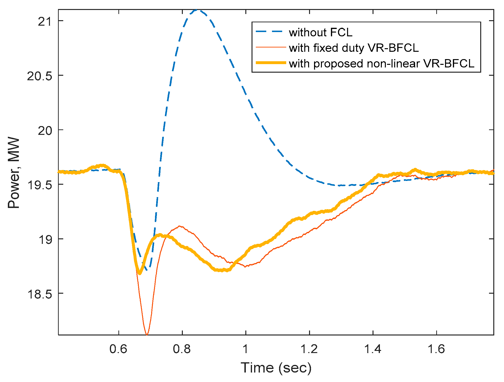
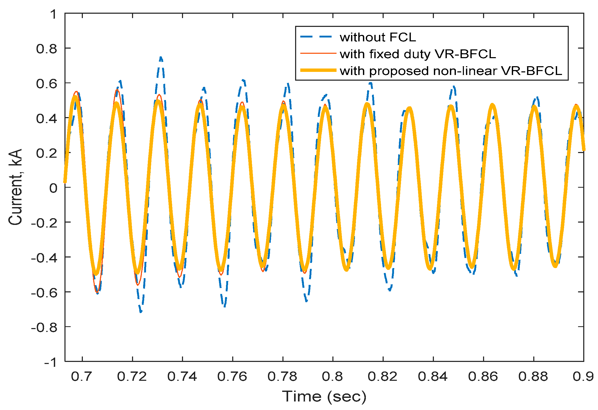
Figure 10 clearly depicts that the oscillation in power exchange between two grids through the HVDC link is higher without any auxiliary controller. The fixed duty controller-based VR-BFCL improves power damping slightly. However, the proposed non-linear controller-based VR-BFCL significantly damps the power oscillation in the system for 3LG fault applied in grid1. The current limiting capability of the non-linear control-based VR-BFCL is clearly visualized in Figure 11.
4.4. Unsymmetrical Faults Application
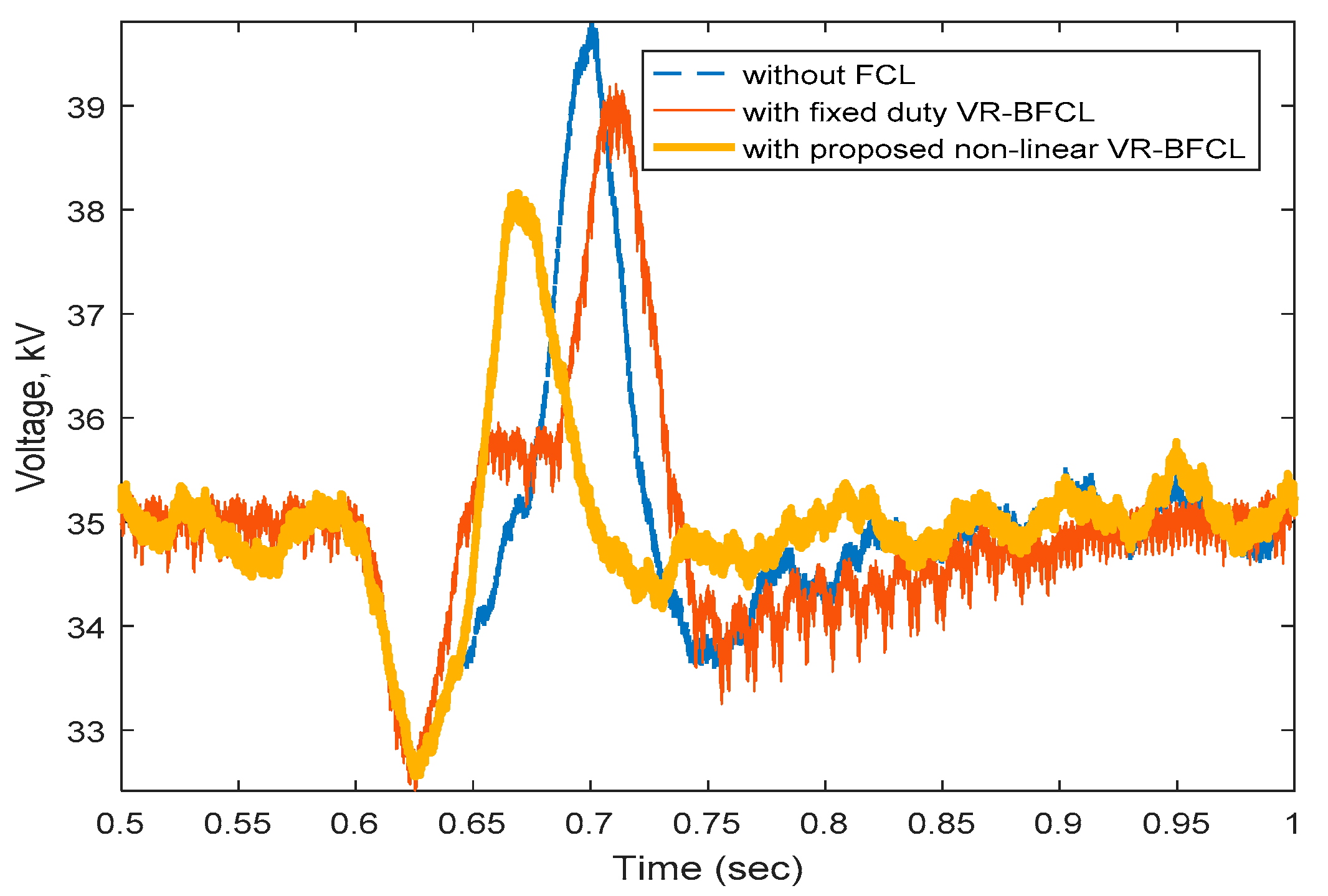
An unsymmetrical single line to ground (1LG) fault has been applied in grid1. The DC link voltage variation, power oscillation and the fault current have been reduced with non-linear control- based VR-BFCL as visualized by the real time simulation results. The fluctuation in the DC voltage is shown in Figure 12 for all the considered cases. Without FCL, the DC link voltage fluctuates between 32.56 kV to 39.75 kV. A DC link voltage fluctuation reduction of 9.87% has been observed with fixed duty control. However, the proposed non-linear control-based VR-BFCL reduces the DC link voltage fluctuation by 24.6%.
As shown in Figure 13, power exchange between grid1 and grid2 oscillates over a wide range without any auxiliary controller. Application of fixed duty control-based VR-BFCL damps the power oscillation by 30.8%. However, the proposed non-linear controller for VR-BFCL gives the best power oscillation damping performance of 50.5%. A maximum level of fault current limiting capability is observed with the proposed non-linear control-based VR-BFCL over without FCL and with the fixed duty VR-BFCL controller for 1LG fault as shown in Figure 14.
4.5. Index-Based Comparison
For a more clear perception of the VSC-HVDC system fault ride through capability enhancement with the proposed non-linear control-based VR-BFCL, several performance indices are evaluated such as DC link voltage, dclinkvolt, active power, acpow, and line current, linecurr. Mathematical representations for the abovementioned indices are given by the following equations:
where , , and represent the deviation of DC link voltage, active power, and line current, respectively. Since the performance index is the total deviation of the signals over the simulation period T, a lower value indicates better system performance. Performance index values for symmetrical and unsymmetrical faults are presented in the Table 2 and Table 3, respectively.
Table 2 and Table 3 show a slight improvement with traditional fixed duty control. However, a notable improvement in FRT capability as well as stability is observed with the proposed non-linear control-based VR-BFCL. Non-linear VR-BFCL shows smaller values for all indices. This demonstrates the better performance for stabilization of the VSC-HVDC system with the proposed control approach.
5. Conclusions
In this work, non-linear control-based VR-BFCL has been proposed for limiting fault currents and augmenting the fault ride through capability of AC/DC systems. Depending on fault detection based on PCC current, VR-BFCL non-linear controller has been designed. The proposed non-linear controller takes the amount of DC link voltage deviation as its input and provides variable duty to generate and insert effective resistance in order to restrict fault current and increase FRT capability. VSC-HVDC plant, VR-BFCL, and the proposed control strategy have been implemented in RTDS. Both balanced and unbalanced faults have been applied in the system to show the proficiency of the proposed controller in improving the FRT capability of the VSC-HVDC system. From real time implementation results, non-linear control-based VR-BFCL has been found as very efficient way of restricting fault current and augmenting the transient response of VSC-HVDC systems. Active power oscillation, DC link voltage fluctuation, and fault current have been reduced significantly and system stability can been guaranteed with the proposed non-linear control-based BR-BFCL. Furthermore, the proposed non-linear control-based VR-BFCL outperforms the traditional fixed duty control as confirmed by the obtained results.
Author Contributions
M.S.A. and M.A.Y.A. initiated the idea, designed the controller and drafted the article. A.E.-D.H. and the other authors performed the simulation, discussion, and revision of the article.
Acknowledgments
The authors would like to acknowledge the support provided by Deanship of Scientific Research, King Fahd University of Petroleum & Minerals, through the funded project # RG171002.
Conflicts of Interest
The authors declare no conflict of interest.
Nomenclature
| Abbreviations | |
| 1LG | Single line to ground fault |
| 3LG | Three line to ground fault |
| D | Duty cycle |
| FFF | Feed forward function |
| FRT | Fault ride through |
| HVDC | High voltage DC |
| IGBT | Insulated gate bipolar transistor |
| LCC | Line commutated converter |
| MTDC | Multiterminal HVDC |
| PCC | Point of common coupling |
| PI | Proportional integral |
| PLL | Phase locked loop |
| RTDS | Real time digital simulator |
| VR-BFCL | Variable resistive bridge type fault current limiter |
| VSC | Voltage source converter |
| Subscripts | |
| aceff | Effective value in AC side |
| d | Direct axis |
| max | Maximum |
| mes | Measured |
| min | Minimum |
| q | Quadrature axis |
| ref | Reference |
| var | Variable |
References
- Lee, J.-G.; Khan, U.A.; Lim, S.-W.; Shin, W.; Seo, I.-J.; Lee, B.-W. Comparative study of superconducting fault current limiter both for LCC-HVDC and VSC-HVDC systems. Phys. C Supercond. Appl. 2015, 518, 149–153. [Google Scholar] [CrossRef]
- Gole, A. Apparent increase in short circuit ratio (AISCR) as a measure of the impact of VSC converters on LCC converters in multi-infeed HVDC systems with VSC and LCC infeeds. In Proceedings of the 10th IET International Conference on AC and DC Power Transmission (ACDC 2012), Birmingham, UK, 4–5 December 2012; Institution of Engineering and Technology: Birmingham, UK, 2012; pp. 22–25. [Google Scholar]
- Alam, M.S.; Abido, M.A.; Al-hamouz, Z.M. Model Predictive Control Approach for Bridge-Type Fault Current Limiter in VSC-HVDC System. Arab. J. Sci. Eng. 2018, 1–11. [Google Scholar] [CrossRef]
- Elansari, A.S.; Finney, S.J.; Burr, J.; Edrah, M.F. Frequency control capability of VSC-HVDC transmission system. In Proceedings of the 11th IET International Conference on AC and DC Power Transmission, Birmingham, UK, 10–12 February 2015; pp. 1–6. [Google Scholar]
- Lei, B.; Zhang, T.; Fei, S. An improved nonlinear robust control design for grid-side converter of VSC-HVDC connected to wind power generation system. Electr. Eng. 2018, 100, 2309–2318. [Google Scholar] [CrossRef]
- Beddard, A.; Barnes, M. Modelling of MMC-HVDC systems—An overview. In Proceedings of the 12th Deep Sea Offshore Wind R&D Conference, Trondheim, Norway, 4–6 February 2015; pp. 201–212. [Google Scholar]
- Kalcon, G.; Adam, G.P.; Anaya-Lara, O.; Burt, G.; Lo, K.L. Analytical efficiency evaluation of two and three level VSC-HVDC transmission links. Int. J. Electr. Power Energy Syst. 2013, 44, 1–6. [Google Scholar] [CrossRef]
- Cao, J.; Du, W.; Wang, H.F. The impact of control design on dynamic behaviour of multi-terminal VSC-HVDC (MTDC) system under AC grid fault conditions. In Proceedings of the 7th IET International Conference on Power Electronics, Machines and Drives, Manchester, UK, 8–10 April 2014; pp. 1–6. [Google Scholar]
- Zhang, L.; Shi, J.; Wang, Z.; Tang, Y.; Yang, Z.; Ren, L.; Yan, S.; Liao, Y. Application of a novel superconducting fault current limiter in a VSC-HVDC system. IEEE Trans. Appl. Supercond. 2017, 27, 1–6. [Google Scholar] [CrossRef]
- Imran, S.; Shah, A.; Batool, M.; Khaliq, A.; Nawaz, F. DC Fault Protection Strategy for Medium Voltage Integrated Power System: Development and Assessment. Arab. J. Sci. Eng. 2018, 43, 2859–2872. [Google Scholar] [CrossRef]
- Alam, M.S.; Chowdhury, A.H. Power System Load Switching Monitoring Using Wavelet Transform Based Multiresolution Signal Decomposition. In Proceedings of the 6th International Conference on Electrical and Computer Engineering (ICECE), Dhaka, Bangladesh, 18–20 December 2010; pp. 18–20. [Google Scholar]
- Li, B.; Li, Y.; He, J. A DC fault handling method of the MMC-based DC system q. Electr. Power Energy Syst. 2017, 93, 39–50. [Google Scholar] [CrossRef]
- Zhang, B.; Zhao, C.; Guo, C.; Xiao, X.; Zhou, L. Controller Architecture Design for MMC-HVDC. Adv. Electr. Comput. Eng. 2014, 14, 9–16. [Google Scholar] [CrossRef]
- Agarwal, S.; Swetapadma, A.; Panigrahi, C. An Improved Method Using Artificial Neural Network for Fault Detection and Fault Pole Identification in Voltage Source Converter-Based High-Voltage Direct Current Transmission Lines. Arab. J. Sci. Eng. 2018, 43, 4005–4018. [Google Scholar] [CrossRef]
- Alam, M.S.; Abido, M.A.Y.; El-Amin, I. Fault Current Limiters in Power Systems: A Comprehensive Review. Energies 2018, 11, 1025. [Google Scholar] [CrossRef]
- Jo, H.C.; Joo, S.K. Superconducting fault current limiter placement for power system protection using the minimax regret criterion. IEEE Trans. Appl. Supercond. 2015, 25. [Google Scholar] [CrossRef]
- Blair, S.M.; Elders, I.M.; Booth, C.D.; Burt, G.M.; McCarthy, J.; Singh, N.K. Superconducting fault current limiter application in a power-dense marine electrical system. IET Electr. Syst. Transp. 2011, 1, 93–102. [Google Scholar] [CrossRef] [Green Version]
- Kim, M.H.; Kim, J.S.; You, I.K.; Lim, S.H.; Kim, J.C. A study on practical impedance of superconducting fault current limiter on bus tie in a power distribution system. J. Int. Counc. Electr. Eng. 2011, 1, 54–59. [Google Scholar] [CrossRef]
- Lee, J.-G.; Khan, U.A.; Hwang, J.-S.; Seong, J.-K.; Shin, W.-J.; Park, B.-B.; Lee, B.-W. Assessment on the influence of resistive superconducting fault current limiter in VSC-HVDC system. Phys. C Supercond. Appl. 2014, 504, 163–166. [Google Scholar] [CrossRef]
- Jo, H.C.; Joo, S.K.; Lee, K. Optimal placement of superconducting fault current limiters (SFCLs) for protection of an electric power system with distributed generations (DGs). IEEE Trans. Appl. Supercond. 2013, 23, 3–6. [Google Scholar] [CrossRef]
- Ye, L.Y.L.; Lin, L.L.L.; Juengst, K.-P. Application studies of superconducting fault current limiters in electric power systems. IEEE Trans. Appl. Supercond. 2002, 12, 900–903. [Google Scholar] [CrossRef]
- Alam, M.S.; Abido, M.A.Y. Fault Ride Through Capability Enhancement of a Large-Scale PMSG Wind System with Bridge Type Fault Current Limiters. Adv. Electr. Comput. Eng. 2018, 18, 43–50. [Google Scholar] [CrossRef]
- Hasan, M.; Rashid, G. Fault ride through capability improvement of DFIG based winds farm by fuzzy logic controlled parallel resonance fault current limiter. Electr. Power Syst. Res. 2016, 146, 1–8. [Google Scholar] [CrossRef]
- Tarafdar, M.T.; Jafari, M.; Naderi, S.B. Transient stability improvement using non-superconducting fault current limiter. In Proceedings of the 1st Power Electronic & Drive Systems & Technologies Conference (PEDSTC), Tehran, Iran, 17–18 February 2010; pp. 367–370. [Google Scholar]
- Hossain, M.K.; Ali, M.H. Transient stability augmentation of PV/DFIG/SG-based hybrid power system by parallel-resonance bridge fault current limiter. Electr. Power Syst. Res. 2016, 130, 89–102. [Google Scholar] [CrossRef]
- Sadi, M.A.H.; Ali, M.H. Transient stability enhancement by bridge type fault current limiter considering coordination with optimal reclosing of circuit breakers. Electr. Power Syst. Res. 2015, 124, 160–172. [Google Scholar] [CrossRef]
- Hossain, M.E. Performance analysis of diode-bridge-type non-superconducting fault current limiter in improving transient stability of DFIG based variable speed wind generator. Electr. Power Syst. Res. 2017, 143, 782–793. [Google Scholar] [CrossRef]
- Hagh, M.T.; Naderi, S.B.; Jafari, M. Application of non-superconducting fault current limiter to improve transient stability. In Proceedings of the IEEE International Conference on Power and Energy, Kuala Lumpur, Malaysia, 19–21 April 2010; pp. 646–650. [Google Scholar]
- Hagh, M.T.; Abapour, M. Nonsuperconducting fault current limiter with controlling the magnitudes of fault currents. IEEE Trans. Power Electron. 2009, 24, 613–619. [Google Scholar] [CrossRef]
- Ise, T.; Nguyen, H.; Kumgai, S. Reduction of inductance and current rating of the coil and enhancement of fault current limiting capability of a rectifier type superconducting fault current limiter. IEEE Trans. Appl. Supercond. 2001, 1, 1932–1935. [Google Scholar] [CrossRef]
- Manohar, P.; Ahmed, W. Superconducting fault current limiter to mitigate the effect of DC line fault in VSC-HVDC system. In Proceedings of the 2012 International Conference on Power, Signals, Controls and Computation, Kerala, India, 3–6 January 2012; pp. 1–6. [Google Scholar]
- Mourinho, F.A.; Motter, D.; Vieira, J.C.M.; Monaro, R.M.; Le Blond, S.P.; Zhang, M.; Yuan, W. Modeling and analysis of superconducting fault current limiters applied in VSC-HVDC systems. In Proceedings of the IEEE Power and Energy Society General Meeting, Denver, CO, USA, 26–30 July 2015; pp. 1–5. [Google Scholar]
- Hoshino, T.; Muta, I.; Nakamura, T.; Salim, K.M.; Yamada, M. Non-inductive variable reactor design and computer simulation of rectifier type superconducting fault current limiter. IEEE Trans. Appl. Supercond. 2005, 15, 2063–2066. [Google Scholar] [CrossRef]
- Kozak, J.; Majka, M.; Kozak, S.; Janowski, T. Comparison of inductive and resistive SFCL. IEEE Trans. Appl. Supercond. 2013, 23, 6–9. [Google Scholar] [CrossRef]
- Ko, S.; Lim, S. Analysis on magnetizing characteristics due to peak fault current limiting operation of a modified flux-lock-type SFCL with two magnetic paths. IEEE Trans. Appl. Supercond. 2016, 26, 4–8. [Google Scholar] [CrossRef]
- Han, T.H.; Ko, S.C.; Lim, S.H. Current limiting characteristics of a flux-lock type SFCL using two triggered HTSC elements. Phys. Procedia 2013, 45, 297–300. [Google Scholar] [CrossRef]
- Ko, S.C.; Han, T.H.; Lim, S.H. Study on peak current limiting characteristics of a flux-lock type SFCL with two magnetically coupled circuits. Phys. Procedia 2013, 45, 305–308. [Google Scholar] [CrossRef]
- Zhao, Y.; Saha, T.K.; Krause, O.; Li, Y. Performance analysis of resistive and flux-lock type SFCL in electricity networks with DGs. In Proceedings of the IEEE Power and Energy Society General Meeting, Denver, CO, USA, 26–30 July 2015; pp. 1–5. [Google Scholar]
- Onishi, T.; Kawasumi, M.; Sasaki, K.I.; Akimoto, R. An experimental study on a fast self-acting magnetic shield type superconducting fault current limiter. IEEE Trans. Appl. Supercond. 2002, 12, 868–871. [Google Scholar] [CrossRef]
- Heydari, H.; Abrishami, A.A.; Bidgoli, M.M. Comprehensive analysis for magnetic shield superconducting fault current limiters. IEEE Trans. Appl. Supercond. 2013, 23. [Google Scholar] [CrossRef]
- Naderi, S.B.; Jafari, M.; Tarafdar Hagh, M. Controllable resistive type fault current limiter (CR-FCL) with frequency and pulse duty-cycle. Int. J. Electr. Power Energy Syst. 2014, 61, 11–19. [Google Scholar] [CrossRef]
- Firouzi, M.; Gharehpetian, G.B.; Mozafari, B. Improvement of power system stability by using new switching technique in bridge-type fault current limiter. Electr. Power Components Syst. 2016, 43, 234–244. [Google Scholar] [CrossRef]
- Hasan, N.; Choudhury, S.H.; Alam, M.S. Performance analysis of a Ĉuk regulator applying variable switching frequency. Int. J. Phys. Sci. 2013, 8, 1753–1760. [Google Scholar] [CrossRef]
- Firouzi, M.; Gharehpetian, G.B.; Pishvaei, M. A dual-functional bridge type FCL to restore PCC voltage. Int. J. Electr. Power Energy Syst. 2013, 46, 49–55. [Google Scholar] [CrossRef]
- Wang, Z.-D.; Li, K.-J.; Ren, J.-G.; Sun, L.-J.; Zhao, J.-G.; Liang, Y.-L.; Lee, W.-J.; Ding, Z.-H.; Sun, Y. A Coordination Control Strategy of Voltage-Source-Converter-Based MTDC for Offshore Wind Farms. IEEE Trans. Ind. Appl. 2015, 51, 2743–2752. [Google Scholar] [CrossRef]
- Lu, M.; Hu, J.; Lin, L.; Xu, K. Zero DC voltage ride through of a hybrid modular multilevel converter in HVDC systems. IET Renew. Power Gener. 2017, 11, 35–43. [Google Scholar] [CrossRef]
- Li, R.; Fletcher, J.E. A novel MMC control scheme to increase the DC voltage in HVDC transmission systems. Electr. Power Syst. Res. 2017, 143, 544–553. [Google Scholar] [CrossRef] [Green Version]
- Alam, M.S.; Abido, M.A.Y. Fault ride-through capability enhancement of voltage source converter-high voltage direct current systems with bridge type fault current limiters. Energies 2017, 10, 1898. [Google Scholar] [CrossRef]
- Alam, M.S.; Hussein, A.; Abido, M.A.; Al-Hamouz, Z.M. VSC-HVDC system stability augmentation with bridge type fault current limiter. In Proceedings of the 6th International Conference on Clean Electrical Power, Santa Margherita Ligure, Italy, 27–29 June 2017; pp. 531–535. [Google Scholar]
- Liu, X.; Wang, P.; Loh, P.C. A hybrid AC/DC microgrid and its coordination control. IEEE Trans. Smart Grid 2011, 2, 278–286. [Google Scholar] [CrossRef]
- Alam, M.S.; Hossain, I.; Hossain, A.; Choudhory, S.H. Protection of Inverter-based Distributed Generation with Series Dynamic Braking Resistor: A Variable Duty Control Approach. In Proceedings of the 2018 10th International Conference on Electrical and Computer Engineering (ICECE), Dhaka, Bangladesh, 20–22 December 2018; pp. 253–256. [Google Scholar]
- Preitl, S.; Precup, R.-E. An extension of tuning relations after symmetrical optimum method for PI and PID controllers. Automatica 1999, 35, 1731–1736. [Google Scholar] [CrossRef]
- Baek, S.-M.; Park, J.-W. Nonlinear parameter optimization of FACTS controller via real-time digital simulator. IEEE Ind. Appl. 2012, 49, 2271–2278. [Google Scholar] [CrossRef]
Figure 1.
Variable resistive bridge type fault current limiter (VR-BFCL).

Figure 2.
Non-linear controller duty variation with voltage deviation for different gains.

Figure 3.
Performance index parameters for different gains.

Figure 4.
Non-linear controller for VR-BFCL.

Figure 5.
Schematic diagram of VSC-HVDC system with VR-BFCL.

Figure 6.
Schematic diagram of controller of VSC1.

Figure 7.
Schematic diagram of the controller of VSC2.

Figure 8.
Real Time Digital Simulator setup.

Figure 9.
DC link voltage response for 3LG fault.

Figure 10.
Response of active power exchange between two grids for 3LG fault.

Figure 11.
Response of Phase ‘a’ current of grid1 for 3LG fault.

Figure 12.
DC link voltage response for 1LG fault.

Figure 13.
Response of active power exchange between two grids for 1LG fault.

Figure 14.
Response of Phase ‘a’ current of grid1 for 1LG fault.


Table 1.
Parameters of the VSC-HVDC system and its controller.
| Parameter | Value |
|---|---|
| Rated power of AC/DC | 30 MVA |
| AC Grid voltage | 138 kV (L-L rms) |
| System Frequency | 60 c/s |
| Transformer voltage ratio | 138/18 kV (Delta/Y) |
| Transformer magnetizing resistance | 0.001 pu |
| Transformer magnetizing inductance | 0.001 pu |
| AC side resistor (R) | 88 mΩ |
| AC side reactor (L) | 8.5 mH |
| DC capacitor | 500 µF |
| DC voltage | 35 kV |
| VR-BFCL resistor (Rvar) | 100 mΩ |
| VR-BFCL inductor (LDC) | 30 mH |
| Current controller | 8.5 + 88/s |
| DC voltage controller | 0.1036 + 17.7/s |
| Feed forward function (FFF) | 1/(1 + 7.5 × 10⁻⁶ s) |
Table 2.
Values of indices with proposed non-linear VR-BFCL for symmetrical 3LG fault.
| Index Parameters, kV.sec | Values of Indices in Percent | ||
|---|---|---|---|
| Without FCL | With Fixed Duty VR-BFCL | With Proposed Nonlinear VR-BFCL | |
| dclinkvolt | 2.0276 | 0.6452 | 0.4623 |
| acpow | 7.8727 | 1.4493 | 0.6301 |
| linecurr | 0.3948 | 0.3360 | 0.3159 |
Table 3.
Values of indices with proposed non-linear VR-BFCL for unsymmetrical 1LG fault.
| Index Parameters, kV.sec | Values of Indices in Percent | ||
|---|---|---|---|
| Without FCL | With Fixed Duty VR-BFCL | With Proposed Nonlinear VR-BFCL | |
| dclinkvolt | 0.5321 | 0.4835 | 0.3831 |
| acpow | 0.6653 | 0.5155 | 0.4485 |
| linecurr | 0.3532 | 0.3029 | 0.3013 |
© 2019 by the authors. Licensee MDPI, Basel, Switzerland. This article is an open access article distributed under the terms and conditions of the Creative Commons Attribution (CC BY) license (http://creativecommons.org/licenses/by/4.0/).
Share and Cite
MDPI and ACS Style
Alam, M.S.; Abido, M.A.Y.; Hussein, A.E.-D. Non-Linear Control for Variable Resistive Bridge Type Fault Current Limiter in AC-DC Systems. Energies 2019, 12, 713. https://doi.org/10.3390/en12040713
AMA Style
Alam MS, Abido MAY, Hussein AE-D. Non-Linear Control for Variable Resistive Bridge Type Fault Current Limiter in AC-DC Systems. Energies. 2019; 12(4):713. https://doi.org/10.3390/en12040713
Chicago/Turabian StyleAlam, Md Shafiul, Mohammad Ali Yousef Abido, and Alaa El-Din Hussein. 2019. "Non-Linear Control for Variable Resistive Bridge Type Fault Current Limiter in AC-DC Systems" Energies 12, no. 4: 713. https://doi.org/10.3390/en12040713
Note that from the first issue of 2016, this journal uses article numbers instead of page numbers. See further details here.